JP2010071722A - Method and device for inspecting unevenness flaws - Google Patents
Method and device for inspecting unevenness flaws Download PDFInfo
- Publication number
- JP2010071722A JP2010071722A JP2008237601A JP2008237601A JP2010071722A JP 2010071722 A JP2010071722 A JP 2010071722A JP 2008237601 A JP2008237601 A JP 2008237601A JP 2008237601 A JP2008237601 A JP 2008237601A JP 2010071722 A JP2010071722 A JP 2010071722A
- Authority
- JP
- Japan
- Prior art keywords
- inspected
- area camera
- information
- image
- luminance
- Prior art date
- Legal status (The legal status is an assumption and is not a legal conclusion. Google has not performed a legal analysis and makes no representation as to the accuracy of the status listed.)
- Granted
Links
Images

Abstract
Description
本発明は板状の被検査体の表面にレーザ光線を照射し、凹凸疵の検査を行う凹凸疵検査方法及び装置に関するものである。 The present invention relates to a method and an apparatus for inspecting an uneven surface by irradiating a surface of a plate-like object with a laser beam to inspect the uneven surface.
例えば製鉄工場において生産されるスラブや厚板鋼板などの表面には、様々な原因により皺や割れなどの凹凸疵が発生することがある。これらの凹凸疵はできるだけ上工程において検出することが好ましく、看過されて下工程に流れたり客先に出荷されたりすると、多数の不良品を発生させる可能性がある。従来は主として目視検査が行われていたが、検査基準が検査員によるため定性的となりばらつきが生じてしまうとともに、スラブ表面の模様やスケールのために見落としが生じ易い。そこで検査基準を定量的としばらつきをなくすとともに、見落としを防止するために、光学的に自動検査する技術が開発されている。 For example, uneven surfaces such as wrinkles and cracks may be generated on the surface of slabs and thick steel plates produced in an iron factory for various reasons. It is preferable to detect these irregularities in the upper process as much as possible. If the irregularities are overlooked and flow to the lower process or are shipped to the customer, a large number of defective products may be generated. Conventionally, visual inspection has been mainly performed. However, since the inspection standard is qualitative and inconsistent due to the inspector, variations occur, and oversight is likely to occur due to the pattern and scale of the slab surface. Therefore, a technique for automatically inspecting optically has been developed in order to make the inspection standard quantitative and eliminate variations, and to prevent oversight.
例えば特許文献1には、スラブの表面に直線的なスリット光と平面的な広がりを持つ2次元光とを同時に照射し、スラブ表面からの反射光を単一のカメラで撮影したうえで前記2種類の光線の波長差を利用して画像を分離し、スリット光によって光切断法による凹凸形状を検出し、2次元光によって表面疵を検出する方法が提案されている。しかしこの方法では2種類の光源を必要とするので光源のメンテナンスに多くの手数を要すること、2次元光は光源からの距離によって反射点の照度が変化してしまうため、スラブの幅方向全体にわたる均一精度の検査が行えないこと、2種類の光源の焦点合わせが難しいことなどの多くの問題があり、実用性に問題があった。
本発明は上記した従来の問題点を解決し、単一の光源によってスラブなどの被検査体の表面に存在する凹凸疵を全幅にわたり精度よく検査することができる凹凸疵検査方法及び装置を提供することを目的とするものである。 The present invention solves the above-described conventional problems and provides a method and apparatus for inspecting uneven wrinkles present on the surface of an object to be inspected such as a slab with a single light source with high accuracy over the entire width. It is for the purpose.
上記の課題を解決するためになされた本発明の凹凸疵検査方法は、長手方向に移動する被検査体の表面に幅方向の線状レーザ光を照射し、その照射位置を斜め上方から所定幅の線状視野を持つエリアカメラにより撮影し、撮影された線状レーザ光の反射位置の変動から被検査体の表面の凹凸情報を取得するとともに、そのエリアカメラの画像に対して長手方向の複数画素分の平均値を幅方向に順次算出して表面輝度画像情報を取得し、これら双方の情報に基づいて被検査体表面の凹凸疵を検査することを特徴とするものである。なお請求項2のように、被検査体が自発光する高温スラブである場合には、線状レーザ光として緑色レーザ光を用いることが好ましい。
In order to solve the above-described problems, the method for inspecting a wrinkle of the present invention irradiates the surface of an object to be inspected moving in the longitudinal direction with a linear laser beam in the width direction, and the irradiation position is obliquely upward from a predetermined width. The image of the surface of the object to be inspected is obtained from the change in the reflection position of the captured linear laser light, and a plurality of longitudinal images are taken with respect to the image of the area camera. Surface luminance image information is obtained by sequentially calculating an average value for pixels in the width direction, and the surface of the object to be inspected is inspected for irregularities on the surface thereof. As in
また請求項3のように、線状レーザ光の反射位置を、エリアカメラの画像中の各画素について長手方向の複数画素の輝度分布を重心演算することによって求め、エリアカメラの分解能を越える精度を得ることが好ましい。また請求項4のように、エリアカメラの画像に対して輝度の閾値を設定し、その閾値を超えた輝度の画素を演算の対象とすることが好ましい。
Further, as described in
また本発明の凹凸疵検査装置は、長手方向に移動する被検査体の表面に幅方向の線状レーザ光を照射するレーザ照射機と、その照射位置を斜め上方から撮影する所定幅の線状視野を持つエリアカメラと、このエリアカメラにより撮影された線状レーザ光の反射位置の変動から被検査体の表面の凹凸情報を演算する凹凸情報演算手段と、このエリアカメラの画像に対して長手方向の複数画素分の平均値を幅方向に順次算出して表面輝度画像情報を演算する輝度画像演算手段とを備えたことを特徴とするものである。 In addition, the uneven wrinkle inspection apparatus according to the present invention includes a laser irradiator that irradiates the surface of an object to be inspected in the longitudinal direction with a linear laser beam in the width direction, and a linear line with a predetermined width that captures the irradiation position obliquely from above. An area camera having a field of view, an unevenness information calculating means for calculating unevenness information on the surface of the object to be inspected from fluctuations in the reflection position of the linear laser light imaged by the area camera, and a longitudinal direction with respect to the image of the area camera Luminance image calculation means for calculating surface luminance image information by sequentially calculating an average value for a plurality of pixels in the direction in the width direction is provided.
本発明によれば、単一の線状レーザ光を被検査体の表面に幅方向に照射し、その反射光を受光したエリアカメラの画像によって光切断法による被検査体の表面の凹凸情報を取得するとともに、同一のエリアカメラの画像から表面輝度画像情報を取得し、これら双方の情報に基づいて被検査体表面の凹凸疵を検査する。このように本発明においては、目視検査を行う場合と同様の表面輝度画像情報を凹凸情報と併用して凹凸疵の検査を行えるので、スラブ表面に模様やスケールがあっても精度のよい検査が可能となる。また本発明においては、光源とカメラはそれぞれ単一であるためにメンテナンスや焦点合わせなどが容易である。また線状レーザ光を用いるので、被検査体の幅方向全体にわたる均一精度の検査が可能である。 According to the present invention, a single linear laser beam is irradiated in the width direction on the surface of the object to be inspected, and unevenness information on the surface of the object to be inspected by the light cutting method is obtained by an image of an area camera that receives the reflected light. While acquiring, surface brightness image information is acquired from the image of the same area camera, and the uneven | corrugated wrinkles on the to-be-inspected object surface are test | inspected based on both information. As described above, in the present invention, since the surface luminance image information similar to that in the case of visual inspection can be used in combination with the unevenness information, the uneven surface can be inspected. It becomes possible. In the present invention, since the light source and the camera are each single, maintenance and focusing are easy. Further, since linear laser light is used, it is possible to inspect with uniform accuracy over the entire width direction of the object to be inspected.
なお被検査体が自発光する高温スラブである場合には、請求項2のように線状レーザ光として緑色レーザ光を用いることにより、スラブ表面からの赤色光との識別が容易となり、正確な検査が可能となる。
When the object to be inspected is a high-temperature slab that emits light by itself, the green laser beam is used as the linear laser beam as in
また光切断法においては線状レーザ光の反射位置の変動から被検査体の表面の凹凸を求めるため、エリアカメラの分解能が問題となるが、請求項3の手法を用いればエリアカメラの分解能を越える精度で検査が可能となる。さらに請求項4のようにエリアカメラの画像中の閾値を超えた輝度の画素を演算の対象とすることにより、線状レーザ光の情報のみを反射位置の算出に使用することが可能となり、外乱による誤差を低減できる。
Further, in the light cutting method, since the unevenness of the surface of the object to be inspected is obtained from the fluctuation of the reflection position of the linear laser beam, the resolution of the area camera becomes a problem. If the method of
以下に本発明の好ましい実施形態を示す。なお以下の実施形態では被検査体はスラブであるがこれに限定されるものではなく、本発明は鋼板などの板状体の検査に広く適用可能である。 Preferred embodiments of the present invention are shown below. In the following embodiments, the object to be inspected is a slab. However, the present invention is not limited to this, and the present invention is widely applicable to inspection of plate-like bodies such as steel plates.
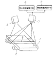
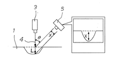
図1において1は被検査体であるスラブであり、搬送用ローラ2によって長手方向に移動している。3はこの被検査体1の表面に幅方向の線状レーザ光を照射するレーザ照射機である。被検査体1の表面における被検査体に対して長手方向の線状レーザ光4の幅は、例えば1〜2mm程度と細くしておくことが検査精度を高めるうえで好ましい。レーザ照射機3は図2に示すようにほぼ垂直下向きに設置されており、この実施形態では垂直面に対して約10°の角度で設定されている。5は被検査体1の表面の照射位置を斜め上方から撮影する所定幅の線状視野を持つエリアカメラである。エリアカメラ5は被検査体1の表面からの線状レーザ光4の反射光を撮影するものである。エリアカメラ5の視野は被検査体1の全幅をカバーするようにしておく。エリアカメラ5の画像は、以下に述べるように凹凸情報演算手段6および輝度画像演算手段7によって演算処理される。これらの凹凸情報演算手段6および輝度画像演算手段7としてはコンピュータが用いられる。
In FIG. 1,
これらのレーザ照射機3とエリアカメラ5と凹凸情報演算手段6とによって、光切断法による被検査体1の凹凸疵の検査が行われる。光切断法自体は公知の手法であり、図2に示すように、被検査体1の表面に深さLの凹部があると、線状レーザ光4の反射位置が垂直方向に変動するため、角度θの方向から撮影した画像がXだけ変化する。ここでL=X/sinθであることを利用して、エリアカメラ5の画像から被検査体1の表面の凹凸情報を取得する手法である。演算は凹凸情報演算手段6によって行われる。θはこの実施形態では45°である。
The
この光切断法の精度はエリアカメラ5の画像の解像度に左右されることとなるが、エリアカメラ5の生画像は図3に示すようにそれぞれが輝度情報を持った画素の集合であり、このままでは画素のサイズ以下の検出精度を得ることができない。すなわち、図3の左側の図は横方向が被検査体1の幅方向、縦方向が被検査体1の長手方向を示し、点線で囲まれた正方形が各画素を示している。この図3の例ではP1位置の輝度がl4、P2位置の輝度がl2、P3位置の輝度がl3、P4位置の輝度がl4であり、最も輝度が高いのはP3位置である。このため線状レーザ光4の反射位置はP3位置付近にあることは分かるが、1画素のサイズ以下の精度は得られない。
The accuracy of this light cutting method depends on the resolution of the image of the
そこでこの実施形態では、線状レーザ光4の反射位置を各画素について長手方向の複数画素の輝度分布を重心演算することによって求めた。まず輝度の閾値をlth=lmax×kthの式により設定する。ここでlmaxは輝度の最大値であり、kthは定数である。図3では閾値lthは輝度の最大値の約1/3に設定(kth=1/3)されており、この閾値を超えた輝度の画素のみを演算の対象とする。ここでは被検査体1の長手方向に分布する4個の画素が演算対象となっている。
Therefore, in this embodiment, the reflection position of the
次に数1の式によって長手方向のレーザ照射位置(反射位置)Preを演算する。分子は長手方向の画素の位置Pkにその画素の輝度lkを掛けた値を1からnまで積算したものであり、ここではn=4である。分母は長手方向の画素の位置Pkを1からnまで積算した値であり、これによって長手方向の輝度分布の重心を演算することができる。演算結果は画素のサイズよりも小さいサブピクセルのレベルを示し、これによって画素のサイズ以下の精度で線状レーザ光4の反射位置を正確に求めることができる。具体的には、画素のサイズは例えば1.2mmであるが、上記した重心演算を行うことにより0.4mmの精度で反射位置の変動を求めることが可能となった。
Next, the laser irradiation position (reflection position) Pre in the longitudinal direction is calculated by the equation (1). The numerator is a value obtained by multiplying the pixel position P k in the longitudinal direction by the luminance l k of the pixel from 1 to n, where n = 4. The denominator is a value obtained by integrating the pixel positions P k in the longitudinal direction from 1 to n, whereby the center of gravity of the luminance distribution in the longitudinal direction can be calculated. The calculation result indicates the level of the sub-pixel smaller than the pixel size, whereby the reflection position of the

このように本発明では、エリアカメラ5の画像中に現れた線状レーザ光4の反射位置の変動に着目して被検査体1の表面の凹凸情報を取得するが、これとともに同一のエリアカメラ5の画像から輝度画像演算手段7によって表面輝度画像情報を取得し、これら双方の情報に基づいて被検査体表面の凹凸疵を検査する。具体的には、エリアカメラ5の画像は図3に示したように被検査体1の幅方向の直線であるが、各画素についてその輝度を被検査体1の長手方向に複数画素分ずつ順次平均して幅方向の輝度分布を求め、これを被検査体1の長手方向に繰り返すことによって平面状の被検査体1の表面輝度画像情報を得る。
As described above, in the present invention, the unevenness information on the surface of the inspected
この平均輝度の演算は、数2の式によって行うことができる。分子は長手方向の画素の位置Pkにその画素の輝度lkを掛けた値を1からnまで積算したものであり、これをnで割ることによって平均輝度が求められる。ただしnは必ずしも4に限定されるものではなく、線状レーザ光4の幅及びエリアカメラ5の分解能(画素のサイズ)によって適宜設定すべきである。
The calculation of the average luminance can be performed by the equation (2). The numerator is a value obtained by multiplying the pixel position P k in the longitudinal direction by the luminance l k of the pixel from 1 to n, and the average luminance is obtained by dividing this by n. However, n is not necessarily limited to 4, and should be appropriately set according to the width of the
このようにして得られた表面輝度画像情報は、従来の人の目による検査を行う場合と同様の画像であり、光切断法のみによっては検出しにくい表面欠陥を検出することができる。また表面輝度画像情報と光切断法による凹凸情報とを併用することによって、スラブ表面に模様やスケールが存在する場合にも、凹凸疵を正確に検出することができる。なお表面輝度画像情報から輝度が異常を示す位置及び大きさを特定できるので、全自動的に合否の判断を行わせることができるが、表面輝度画像情報はモニタに表示させ、熟練した検査員による確認を行わせることも可能である。 The surface luminance image information obtained in this way is an image similar to that in the case of conventional inspection by the human eye, and can detect surface defects that are difficult to detect only by the light cutting method. Further, by using the surface luminance image information and the unevenness information obtained by the light cutting method in combination, even when a pattern or scale exists on the surface of the slab, the uneven surface can be accurately detected. Since the position and size where the luminance is abnormal can be specified from the surface luminance image information, it is possible to make a pass / fail judgment fully automatically. However, the surface luminance image information is displayed on the monitor and can be obtained by a skilled inspector. It is also possible to make confirmation.
なお、被検査体1が赤色光を自発光する高温スラブである場合には、4の反射光が検出しにくくなるおそれがある。その場合には、波長が532nmの緑色レーザ光を使用することにより、赤色光との識別が容易となる。さらにレーザ照射機3とエリアカメラ5とに熱線を反射するフィルタを取り付けるとともに、エリアカメラ5に帯域通過フィルター(バンドパスフィルター:BPF)を取付けて、光の波長に応じて光の検出情報を選択的に通過させたり遮断することができるようにしておけば、高温スラブからの赤色光を遮断できるのでより好ましい検出精度を得ることができる。
In addition, when the to-
以上に説明したように、本発明においては光切断法による凹凸疵の検査を行うためのレーザ照射機とエリアカメラとを用い、エリアカメラの画像を被検査体の長手方向に複数画素分ずつ順次平均して表面輝度画像情報を演算することにより表面輝度画像情報を取得し、これら双方の情報に基づいて被検査体表面の凹凸疵を検査する。このため、目視検査を行う場合と同様の表面輝度画像情報を凹凸情報と併用して凹凸疵の検査を行えるので、スラブ表面に模様やスケールがあっても精度のよい検査が可能となる。また光源とカメラはそれぞれ単一であるためにメンテナンスが容易となり、また従来のような複数光源の焦点合わせなどは不要となるうえ、線状レーザ光を用いるために被検査体の全幅にわたり均一精度での検査が可能となる。 As described above, in the present invention, a laser irradiator and an area camera for inspecting uneven ridges by a light cutting method are used, and an image of the area camera is sequentially provided for a plurality of pixels in the longitudinal direction of the object to be inspected. The surface luminance image information is obtained by calculating the surface luminance image information on the average, and the surface of the object to be inspected is inspected for unevenness on the basis of both pieces of information. For this reason, since the same surface luminance image information as in the case of visual inspection can be used in combination with the unevenness information, the uneven surface can be inspected, so that even if there is a pattern or scale on the slab surface, an accurate inspection can be performed. In addition, since the light source and the camera are each single, maintenance is easy, and focusing of multiple light sources as in the past is not required, and since linear laser light is used, uniform accuracy over the entire width of the object to be inspected Inspection at can be performed.
1 被検査体
2 搬送用ローラ
3 レーザ照射機
4 線状レーザ光
5 エリアカメラ
6 凹凸情報演算手段
7 輝度画像演算手段
DESCRIPTION OF
Claims (5)
Priority Applications (1)
| Application Number | Priority Date | Filing Date | Title |
|---|---|---|---|
| JP2008237601A JP5488953B2 (en) | 2008-09-17 | 2008-09-17 | Method and apparatus for inspection of uneven surface |
Applications Claiming Priority (1)
| Application Number | Priority Date | Filing Date | Title |
|---|---|---|---|
| JP2008237601A JP5488953B2 (en) | 2008-09-17 | 2008-09-17 | Method and apparatus for inspection of uneven surface |
Publications (2)
| Publication Number | Publication Date |
|---|---|
| JP2010071722A true JP2010071722A (en) | 2010-04-02 |
| JP5488953B2 JP5488953B2 (en) | 2014-05-14 |
Family
ID=42203667
Family Applications (1)
| Application Number | Title | Priority Date | Filing Date |
|---|---|---|---|
| JP2008237601A Active JP5488953B2 (en) | 2008-09-17 | 2008-09-17 | Method and apparatus for inspection of uneven surface |
Country Status (1)
| Country | Link |
|---|---|
| JP (1) | JP5488953B2 (en) |
Cited By (10)
| Publication number | Priority date | Publication date | Assignee | Title |
|---|---|---|---|---|
| CN102853786A (en) * | 2012-08-31 | 2013-01-02 | 深圳先进技术研究院 | Apparatus and method for detecting flatness |
| KR101518592B1 (en) | 2013-10-15 | 2015-05-15 | 주식회사 포스코 | Apparatus and method of correcting surface image of scrfed slab |
| WO2016171265A1 (en) * | 2015-04-22 | 2016-10-27 | 新日鐵住金株式会社 | Shape-measuring device and method for measuring shape |
| JP2018048979A (en) * | 2016-09-23 | 2018-03-29 | 新日鐵住金株式会社 | Surface property inspection apparatus, surface property insection method, and program |
| CN108818544A (en) * | 2018-06-05 | 2018-11-16 | 科芃智能科技(苏州)有限公司 | The strip surfacing machine people of view-based access control model guiding |
| KR102011790B1 (en) * | 2018-05-16 | 2019-08-19 | 라온피플 주식회사 | Method and appratus for inspecting product using laser |
| JP2020016667A (en) * | 2019-10-25 | 2020-01-30 | 東急建設株式会社 | Inspection device for deformed part |
| CN110987954A (en) * | 2019-12-30 | 2020-04-10 | 江南大学 | Method and system for eliminating leather surface defect detection blind area |
| CN112432952A (en) * | 2020-11-20 | 2021-03-02 | 中国电子科技集团公司第四十一研究所 | Cigarette loose end detection method based on machine vision technology |
| CN112432953A (en) * | 2020-11-20 | 2021-03-02 | 中国电子科技集团公司第四十一研究所 | Cigarette packet missing and reverse detection method based on machine vision technology |
Families Citing this family (2)
| Publication number | Priority date | Publication date | Assignee | Title |
|---|---|---|---|---|
| US10274314B2 (en) | 2015-05-13 | 2019-04-30 | Nippon Steel & Sumitomo Metal Corporation | Shape inspection method, shape inspection apparatus, and program |
| KR101945662B1 (en) | 2016-06-27 | 2019-02-07 | 신닛테츠스미킨 카부시키카이샤 | Shape measuring device and shape measuring method |
Citations (29)
| Publication number | Priority date | Publication date | Assignee | Title |
|---|---|---|---|---|
| JPS618610A (en) * | 1984-06-22 | 1986-01-16 | Sumitomo Metal Ind Ltd | Apparatus for inspecting steel sheet surface |
| JPS62220803A (en) * | 1986-03-20 | 1987-09-29 | Toyota Central Res & Dev Lab Inc | Three-dimensional coordinate measuring instrument |
| JPS62289752A (en) * | 1986-06-10 | 1987-12-16 | Toshiba Corp | Surface inspecting device |
| JPS63132107A (en) * | 1986-11-25 | 1988-06-04 | Hitachi Ltd | Light cutting line extracting circuit |
| JPS63274806A (en) * | 1987-05-01 | 1988-11-11 | Nippon Steel Corp | Detection of shape of slip in continuous annealing furnace |
| JPS6476167A (en) * | 1987-09-17 | 1989-03-22 | Agency Ind Science Techn | Linear light extracting circuit |
| JPH02187609A (en) * | 1988-11-28 | 1990-07-23 | Allegheny Internatl Inc | System for generating surface image of metal work, measurement of ruggedness of surface thereof and apparatus for generating surface image of continuously cast slab |
| JPH03205503A (en) * | 1990-01-08 | 1991-09-09 | Mitsubishi Heavy Ind Ltd | Image position detecting method for sheet light |
| JPH0438407A (en) * | 1990-06-01 | 1992-02-07 | Kawasaki Steel Corp | Method for positioning video camera |
| JPH05196461A (en) * | 1992-01-23 | 1993-08-06 | Sumitomo Metal Ind Ltd | Method of measuring distance with laser |
| JPH06148098A (en) * | 1992-09-18 | 1994-05-27 | Kawasaki Steel Corp | Surface defect inspection apparatus |
| JPH07239221A (en) * | 1993-05-24 | 1995-09-12 | Komatsu Ltd | Bending angle detector and linear extracting device and device for setting bending angle detection position therefor |
| JPH0843045A (en) * | 1994-07-26 | 1996-02-16 | Tokai Rika Co Ltd | Three dimensional measuring apparatus |
| JPH09152322A (en) * | 1995-11-30 | 1997-06-10 | Nippon Steel Corp | Method and device for surface quality inspection |
| JPH11142122A (en) * | 1997-09-04 | 1999-05-28 | Matsushita Electric Ind Co Ltd | Range finder |
| JP2000292123A (en) * | 1999-04-05 | 2000-10-20 | Toshiba Corp | Shape measuring apparatus |
| JP2001012918A (en) * | 1999-07-01 | 2001-01-19 | Nkk Corp | Coil position-detecting device |
| JP2001255275A (en) * | 2000-03-13 | 2001-09-21 | Kawasaki Steel Corp | Surface defect inspection method and device |
| JP2001296252A (en) * | 2000-04-11 | 2001-10-26 | Matsushita Electric Works Ltd | Defect detection method of object surface, and device thereof |
| JP2002148196A (en) * | 2000-11-15 | 2002-05-22 | Nippon Steel Corp | Shading correcting method |
| JP2005030812A (en) * | 2003-07-08 | 2005-02-03 | Nippon Steel Corp | Method for inspecting surface of steel panel, inspection system, image processor, and computer program |
| JP2005134362A (en) * | 2003-05-07 | 2005-05-26 | Nippon Steel Corp | Inspection method and inspection device for surface irregularity |
| JP2005189113A (en) * | 2003-12-25 | 2005-07-14 | Jfe Steel Kk | Surface inspecting device and surface inspection method |
| JP2006177852A (en) * | 2004-12-24 | 2006-07-06 | Toshiba Corp | Surface inspection device and its method |
| JP2007101359A (en) * | 2005-10-04 | 2007-04-19 | Nippon Steel Corp | Flaw detector and flaw detection method |
| JP2007132858A (en) * | 2005-11-11 | 2007-05-31 | Nippon Steel Corp | Flaw detection method, device and computer program |
| JP2008134148A (en) * | 2006-11-28 | 2008-06-12 | Kobe Steel Ltd | Sectional shape measuring method and sectional shape measuring device |
| JP2008175625A (en) * | 2007-01-17 | 2008-07-31 | Konica Minolta Sensing Inc | Three-dimensional measurement apparatus and portable gauge |
| JP2008203198A (en) * | 2007-02-22 | 2008-09-04 | Nippon Steel Corp | Surface flaw inspecting system and flaw method, and computer program |
-
2008
- 2008-09-17 JP JP2008237601A patent/JP5488953B2/en active Active
Patent Citations (29)
| Publication number | Priority date | Publication date | Assignee | Title |
|---|---|---|---|---|
| JPS618610A (en) * | 1984-06-22 | 1986-01-16 | Sumitomo Metal Ind Ltd | Apparatus for inspecting steel sheet surface |
| JPS62220803A (en) * | 1986-03-20 | 1987-09-29 | Toyota Central Res & Dev Lab Inc | Three-dimensional coordinate measuring instrument |
| JPS62289752A (en) * | 1986-06-10 | 1987-12-16 | Toshiba Corp | Surface inspecting device |
| JPS63132107A (en) * | 1986-11-25 | 1988-06-04 | Hitachi Ltd | Light cutting line extracting circuit |
| JPS63274806A (en) * | 1987-05-01 | 1988-11-11 | Nippon Steel Corp | Detection of shape of slip in continuous annealing furnace |
| JPS6476167A (en) * | 1987-09-17 | 1989-03-22 | Agency Ind Science Techn | Linear light extracting circuit |
| JPH02187609A (en) * | 1988-11-28 | 1990-07-23 | Allegheny Internatl Inc | System for generating surface image of metal work, measurement of ruggedness of surface thereof and apparatus for generating surface image of continuously cast slab |
| JPH03205503A (en) * | 1990-01-08 | 1991-09-09 | Mitsubishi Heavy Ind Ltd | Image position detecting method for sheet light |
| JPH0438407A (en) * | 1990-06-01 | 1992-02-07 | Kawasaki Steel Corp | Method for positioning video camera |
| JPH05196461A (en) * | 1992-01-23 | 1993-08-06 | Sumitomo Metal Ind Ltd | Method of measuring distance with laser |
| JPH06148098A (en) * | 1992-09-18 | 1994-05-27 | Kawasaki Steel Corp | Surface defect inspection apparatus |
| JPH07239221A (en) * | 1993-05-24 | 1995-09-12 | Komatsu Ltd | Bending angle detector and linear extracting device and device for setting bending angle detection position therefor |
| JPH0843045A (en) * | 1994-07-26 | 1996-02-16 | Tokai Rika Co Ltd | Three dimensional measuring apparatus |
| JPH09152322A (en) * | 1995-11-30 | 1997-06-10 | Nippon Steel Corp | Method and device for surface quality inspection |
| JPH11142122A (en) * | 1997-09-04 | 1999-05-28 | Matsushita Electric Ind Co Ltd | Range finder |
| JP2000292123A (en) * | 1999-04-05 | 2000-10-20 | Toshiba Corp | Shape measuring apparatus |
| JP2001012918A (en) * | 1999-07-01 | 2001-01-19 | Nkk Corp | Coil position-detecting device |
| JP2001255275A (en) * | 2000-03-13 | 2001-09-21 | Kawasaki Steel Corp | Surface defect inspection method and device |
| JP2001296252A (en) * | 2000-04-11 | 2001-10-26 | Matsushita Electric Works Ltd | Defect detection method of object surface, and device thereof |
| JP2002148196A (en) * | 2000-11-15 | 2002-05-22 | Nippon Steel Corp | Shading correcting method |
| JP2005134362A (en) * | 2003-05-07 | 2005-05-26 | Nippon Steel Corp | Inspection method and inspection device for surface irregularity |
| JP2005030812A (en) * | 2003-07-08 | 2005-02-03 | Nippon Steel Corp | Method for inspecting surface of steel panel, inspection system, image processor, and computer program |
| JP2005189113A (en) * | 2003-12-25 | 2005-07-14 | Jfe Steel Kk | Surface inspecting device and surface inspection method |
| JP2006177852A (en) * | 2004-12-24 | 2006-07-06 | Toshiba Corp | Surface inspection device and its method |
| JP2007101359A (en) * | 2005-10-04 | 2007-04-19 | Nippon Steel Corp | Flaw detector and flaw detection method |
| JP2007132858A (en) * | 2005-11-11 | 2007-05-31 | Nippon Steel Corp | Flaw detection method, device and computer program |
| JP2008134148A (en) * | 2006-11-28 | 2008-06-12 | Kobe Steel Ltd | Sectional shape measuring method and sectional shape measuring device |
| JP2008175625A (en) * | 2007-01-17 | 2008-07-31 | Konica Minolta Sensing Inc | Three-dimensional measurement apparatus and portable gauge |
| JP2008203198A (en) * | 2007-02-22 | 2008-09-04 | Nippon Steel Corp | Surface flaw inspecting system and flaw method, and computer program |
Cited By (17)
| Publication number | Priority date | Publication date | Assignee | Title |
|---|---|---|---|---|
| CN102853786A (en) * | 2012-08-31 | 2013-01-02 | 深圳先进技术研究院 | Apparatus and method for detecting flatness |
| KR101518592B1 (en) | 2013-10-15 | 2015-05-15 | 주식회사 포스코 | Apparatus and method of correcting surface image of scrfed slab |
| KR101968439B1 (en) * | 2015-04-22 | 2019-04-11 | 신닛테츠스미킨 카부시키카이샤 | Shape measuring device and shape measuring method |
| US10295335B2 (en) | 2015-04-22 | 2019-05-21 | Nippon Steel & Sumitomo Metal Corporation | Shape measurement apparatus and shape measurement method |
| JPWO2016171265A1 (en) * | 2015-04-22 | 2017-12-28 | 新日鐵住金株式会社 | Shape measuring apparatus and shape measuring method |
| KR20170136619A (en) * | 2015-04-22 | 2017-12-11 | 신닛테츠스미킨 카부시키카이샤 | Shape measuring device and shape measuring method |
| EP3270101A4 (en) * | 2015-04-22 | 2018-08-29 | Nippon Steel & Sumitomo Metal Corporation | Shape-measuring device and method for measuring shape |
| WO2016171265A1 (en) * | 2015-04-22 | 2016-10-27 | 新日鐵住金株式会社 | Shape-measuring device and method for measuring shape |
| JP2018048979A (en) * | 2016-09-23 | 2018-03-29 | 新日鐵住金株式会社 | Surface property inspection apparatus, surface property insection method, and program |
| KR102011790B1 (en) * | 2018-05-16 | 2019-08-19 | 라온피플 주식회사 | Method and appratus for inspecting product using laser |
| CN108818544A (en) * | 2018-06-05 | 2018-11-16 | 科芃智能科技(苏州)有限公司 | The strip surfacing machine people of view-based access control model guiding |
| CN108818544B (en) * | 2018-06-05 | 2019-10-25 | 科芃智能科技(苏州)有限公司 | The strip surfacing machine people of view-based access control model guiding |
| JP2020016667A (en) * | 2019-10-25 | 2020-01-30 | 東急建設株式会社 | Inspection device for deformed part |
| CN110987954A (en) * | 2019-12-30 | 2020-04-10 | 江南大学 | Method and system for eliminating leather surface defect detection blind area |
| CN112432952A (en) * | 2020-11-20 | 2021-03-02 | 中国电子科技集团公司第四十一研究所 | Cigarette loose end detection method based on machine vision technology |
| CN112432953A (en) * | 2020-11-20 | 2021-03-02 | 中国电子科技集团公司第四十一研究所 | Cigarette packet missing and reverse detection method based on machine vision technology |
| CN112432953B (en) * | 2020-11-20 | 2024-03-15 | 中国电子科技集团公司第四十一研究所 | Cigarette pack missing and anti-cigarette detection method based on machine vision technology |
Also Published As
| Publication number | Publication date |
|---|---|
| JP5488953B2 (en) | 2014-05-14 |
Similar Documents
| Publication | Publication Date | Title |
|---|---|---|
| JP5488953B2 (en) | Method and apparatus for inspection of uneven surface | |
| CN107735674B (en) | Surface defect detection device, surface defect detection method, and steel product manufacturing method | |
| KR101832081B1 (en) | Surface defect detection method and surface defect detection device | |
| JP6394514B2 (en) | Surface defect detection method, surface defect detection apparatus, and steel material manufacturing method | |
| JP4322890B2 (en) | Undulation inspection device, undulation inspection method, control program of undulation inspection device, recording medium | |
| US20200110025A1 (en) | Multi-Parameter Inspection Apparatus for Monitoring of Manufacturing Parts | |
| JP2012514193A (en) | Non-destructive inspection method for machine parts | |
| JP5828817B2 (en) | Shape inspection method for steel bars | |
| WO2016208626A1 (en) | Surface flaw detection method, surface flaw detection device, and manufacturing method for steel material | |
| US20230258578A1 (en) | Multi-Parameter Inspection Apparatus for Monitoring of Manufacturing Parts | |
| JP5494566B2 (en) | Defect detection method for steel | |
| CA2825678A1 (en) | Method and device for inspecting an object for the detection of surface damage | |
| TW201140043A (en) | End face inspection method for light-pervious rectangular sheets and end face inspection apparatus | |
| JP2006010392A (en) | Through hole measuring system, method, and through hole measuring program | |
| JPWO2012042582A1 (en) | Glass bottle inspection equipment | |
| JP5992315B2 (en) | Surface defect detection device and surface defect detection method | |
| JP2019056671A (en) | Wall surface damage inspection device | |
| JP7098111B2 (en) | Surface inspection equipment and surface inspection method | |
| JP2017062181A (en) | Surface flaw checkup apparatus, and surface flaw checkup method | |
| JP2015200544A (en) | Surface irregularity inspection device and surface irregularity inspection method | |
| JP2021067588A (en) | Surface inspection device for object to be inspected and surface inspection method for object to be inspected | |
| JP5570890B2 (en) | Tire appearance inspection method and appearance inspection apparatus | |
| JP4797568B2 (en) | Slab vertical crack detection method and apparatus | |
| JP3671157B2 (en) | Non-contact visual inspection method and apparatus | |
| JP6146389B2 (en) | Steel surface inspection apparatus and method |
Legal Events
| Date | Code | Title | Description |
|---|---|---|---|
| A621 | Written request for application examination |
Free format text: JAPANESE INTERMEDIATE CODE: A621 Effective date: 20100810 |
|
| A977 | Report on retrieval |
Free format text: JAPANESE INTERMEDIATE CODE: A971007 Effective date: 20120203 |
|
| A131 | Notification of reasons for refusal |
Free format text: JAPANESE INTERMEDIATE CODE: A131 Effective date: 20120207 |
|
| A521 | Written amendment |
Free format text: JAPANESE INTERMEDIATE CODE: A523 Effective date: 20120409 |
|
| A131 | Notification of reasons for refusal |
Free format text: JAPANESE INTERMEDIATE CODE: A131 Effective date: 20130312 |
|
| TRDD | Decision of grant or rejection written | ||
| A01 | Written decision to grant a patent or to grant a registration (utility model) |
Free format text: JAPANESE INTERMEDIATE CODE: A01 Effective date: 20140131 |
|
| A61 | First payment of annual fees (during grant procedure) |
Free format text: JAPANESE INTERMEDIATE CODE: A61 Effective date: 20140213 |
|
| R151 | Written notification of patent or utility model registration |
Ref document number: 5488953 Country of ref document: JP Free format text: JAPANESE INTERMEDIATE CODE: R151 |
|
| S533 | Written request for registration of change of name |
Free format text: JAPANESE INTERMEDIATE CODE: R313533 |
|
| R350 | Written notification of registration of transfer |
Free format text: JAPANESE INTERMEDIATE CODE: R350 |