JP2010068024A - Thermoregulator - Google Patents
Thermoregulator Download PDFInfo
- Publication number
- JP2010068024A JP2010068024A JP2008229766A JP2008229766A JP2010068024A JP 2010068024 A JP2010068024 A JP 2010068024A JP 2008229766 A JP2008229766 A JP 2008229766A JP 2008229766 A JP2008229766 A JP 2008229766A JP 2010068024 A JP2010068024 A JP 2010068024A
- Authority
- JP
- Japan
- Prior art keywords
- rectification
- sampling
- voltage conversion
- conversion
- voltage
- Prior art date
- Legal status (The legal status is an assumption and is not a legal conclusion. Google has not performed a legal analysis and makes no representation as to the accuracy of the status listed.)
- Pending
Links
Images

Abstract
Description
本発明は、制御対象の温度を調整する温度調節計に関し、特に、低速のA/Dコンバータを用いても量子化誤差を少なくできる温度調節計に関する。 The present invention relates to a temperature controller that adjusts the temperature of an object to be controlled, and more particularly to a temperature controller that can reduce quantization error even when a low-speed A / D converter is used.
温度調節計(ディジタル指示調節計)は、例えば炉などの制御対象の温度を一定に保つため、ヒーターを用いて温度を調整している。しかし、このヒーターが断線すると温度の調節ができなくなるため、ヒーター断線検出機能を備えた温度調節計は、このヒーターに流れる電流(ヒーター電流)を利用して断線を検出する。 The temperature controller (digital indicating controller) adjusts the temperature using a heater in order to keep the temperature of a controlled object such as a furnace constant. However, since the temperature cannot be adjusted when the heater is disconnected, the temperature controller equipped with the heater disconnection detection function detects disconnection using the current (heater current) flowing through the heater.
ここで、ヒーターの断線検出は次の様に行われる。まず、ヒーターに流れる電流の信号線を、コイルが内蔵されたリング状のCT(Current Trans,カレント・トランス)でクランプする。 Here, the disconnection detection of the heater is performed as follows. First, the signal line of the current flowing through the heater is clamped by a ring-shaped CT (Current Trans) having a built-in coil.
CTに内蔵されたコイルは、CTに囲まれた信号線から生じる磁束によって誘導電流(ヒーター変流電流)を発生する。温度調節計は、このヒーター変流電流を用いてヒーターの断線を検出する。温度調節計の先行技術文献としては次のようなものがある。 A coil built in the CT generates an induced current (heater current) by a magnetic flux generated from a signal line surrounded by the CT. The temperature controller detects the disconnection of the heater using the heater current. Prior art documents on temperature controllers include the following.
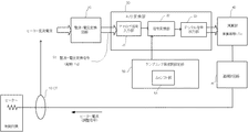
以下、図4を参照して従来の温度調節計を説明する。CT(非接触電流センサ)10は、計器用変流器であり、上述のように、内蔵されたコイルが、リング状のCTに囲まれた信号線から生じる磁束によってヒーター変流電流を発生する。整流・電圧変換回路20はこのヒーター変流電流を整流・電圧変換信号S1(電圧信号)に変換する。 Hereinafter, a conventional temperature controller will be described with reference to FIG. The CT (non-contact current sensor) 10 is a current transformer for an instrument. As described above, a built-in coil generates a heater current by a magnetic flux generated from a signal line surrounded by a ring-shaped CT. . The rectification / voltage conversion circuit 20 converts the heater current conversion current into a rectification / voltage conversion signal S1 (voltage signal).
A/D変換部30は、アナログ信号入力部31,信号変換部32,デジタル信号出力部33からなる。アナログ信号入力部31は、整流・電圧変換回路20から周期がTdの整流・電圧変換信号S1が入力される。 The A / D conversion unit 30 includes an analog signal input unit 31, a signal conversion unit 32, and a digital signal output unit 33. The analog signal input unit 31 receives a rectification / voltage conversion signal S1 having a cycle of Td from the rectification / voltage conversion circuit 20.
信号変換部32は、アナログ信号入力部31から出力された信号を、サンプリング周波数設定部50で設定されるサンプリング周波数に従ってA/D変換する。デジタル信号出力部33は、信号変換部32から出力されたデジタル信号を演算部40に出力する。 The signal conversion unit 32 performs A / D conversion on the signal output from the analog signal input unit 31 according to the sampling frequency set by the sampling frequency setting unit 50. The digital signal output unit 33 outputs the digital signal output from the signal conversion unit 32 to the calculation unit 40.
演算部40は、周期がTdからなる整流・電圧変換信号の複数の周期(以下「演算周期Tc」という)分のサンプリングデータを用いて演算を行う。 The calculation unit 40 performs calculation using sampling data for a plurality of cycles (hereinafter referred to as “calculation cycle Tc”) of the rectification / voltage conversion signal having a cycle of Td.
温調計回路41は、CPU,記憶部等で構成され、温度調節計の一般的な機能を実現するとともに、ヒーター電流を出力してヒーターを制御することにより、制御対象の温度を調節する。 The temperature controller circuit 41 is configured by a CPU, a storage unit, and the like, realizes the general function of the temperature controller, and adjusts the temperature of the controlled object by outputting a heater current to control the heater.
サンプリング周波数設定部50は、例えば100MHzのサンプリング周波数でA/D変換を行う旨の信号を信号変換部32に出力する。 The sampling frequency setting unit 50 outputs a signal indicating that A / D conversion is performed at a sampling frequency of 100 MHz, for example, to the signal conversion unit 32.
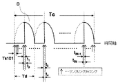
次に、図5を参照して図1のA/Dサンプリングのタイミングを説明する。図5より、周期がTdからなる整流・電圧変換信号S1の複数の周期分が、演算周期Tcとなる。 Next, the timing of A / D sampling in FIG. 1 will be described with reference to FIG. From FIG. 5, a plurality of cycles of the rectification / voltage conversion signal S1 having a cycle of Td is the calculation cycle Tc.
すなわち、整流・電圧変換信号S1の周波数がf1,f2,・・・,fnと変化した場合でも、演算周期Tcは、複数の周期Td(つまりf1の逆数,f2の逆数,・・・,fnの逆数)のいずれに対しても整数倍の関係にある自然数である必要がある。 That is, even when the frequency of the rectification / voltage conversion signal S1 changes to f1, f2,..., Fn, the calculation cycle Tc has a plurality of cycles Td (that is, the reciprocal of f1, the reciprocal of f2,..., Fn). It is necessary to be a natural number that is an integer multiple of the reciprocal number).
また、図5においてA/D変換のサンプリング周期Ts1は、整流・電圧変換信号の周期Td=Ts1×M(Mは自然数)となる値が選ばれ、電流・電圧変換信号の各周期において全て同じタイミングでA/Dサンプリングが行われる。 In FIG. 5, the sampling period Ts1 for A / D conversion is selected to have a rectification / voltage conversion signal period Td = Ts1 × M (M is a natural number), and is the same in each period of the current / voltage conversion signal. A / D sampling is performed at the timing.
このように、従来の温度調節計では、電流・電圧変換信号の各周期Tdにおいて全て同じタイミングでA/Dサンプリングを行っていた。 As described above, in the conventional temperature controller, A / D sampling is performed at the same timing in each period Td of the current / voltage conversion signal.
しかし、繰り返し波形の「立ちあがり」とサンプリングタイミングが非常に近いとき(図5でΔt0が非常に小さいとき)、は量子化誤差が大きくなる。この量子化誤差はA/D変換部30のサンプリング速度が高速であれば少なくなるが、一般に高速のA/Dコンバータは高価である。 However, when the sampling timing is very close to the “rise” of the repetitive waveform (when Δt0 is very small in FIG. 5), the quantization error becomes large. This quantization error is reduced if the sampling rate of the A / D converter 30 is high, but generally a high-speed A / D converter is expensive.
本発明は、これらの問題点に鑑みてなされたものであり、低速のA/Dコンバータを用いても量子化誤差が少ないヒーター断線検出機能を備えた温度調節計を提供することを目的とする。 The present invention has been made in view of these problems, and it is an object of the present invention to provide a temperature controller having a heater disconnection detection function with little quantization error even when a low-speed A / D converter is used. .
この様な課題を達成するために本発明は以下の構成を備える。
(1)非接触電流センサによって変流された周期信号からなるヒーター変流電流を電圧に変換する整流・電圧変換回路と、この整流・電圧変換回路から出力された整流・電圧変換信号をA/D変換するA/D変換部を備え、制御対象の温度を目標値に調節する温度調節計において、
前記整流・電圧変換信号の周期≠サンプリング周期×M(自然数)となるタイミングでサンプリングを行う旨を前記A/D変換部に出力するサンプリング周波数設定部を備えたことを特徴とする温度調節計。
(2)非接触電流センサによって変流された周期信号からなるヒーター変流電流を電圧に変換する整流・電圧変換回路と、この整流・電圧変換回路から出力された整流・電圧変換信号をA/D変換するA/D変換部を備え、制御対象の温度を目標値に調節する温度調節計において、
サンプリングのタイミングが前記整流・電圧変換信号の各周期で重ならないようにサンプリングを行う旨を前記A/D変換部に出力するサンプリング周波数設定部を備えたことを特徴とする温度調節計。
In order to achieve such a problem, the present invention has the following configuration.
(1) A rectification / voltage conversion circuit that converts a heater current, which is a periodic signal that has been converted by a non-contact current sensor, into a voltage, and a rectification / voltage conversion signal that is output from the rectification / voltage conversion circuit as A / In a temperature controller that includes an A / D conversion unit that performs D conversion and adjusts the temperature of a control target to a target value,
A temperature controller comprising: a sampling frequency setting unit that outputs to the A / D conversion unit that sampling is performed at a timing such that the cycle of the rectification / voltage conversion signal ≠ sampling cycle × M (natural number).
(2) A rectification / voltage conversion circuit that converts a heater current converted from a periodic signal converted by a non-contact current sensor into a voltage, and a rectification / voltage conversion signal output from the rectification / voltage conversion circuit as A / In a temperature controller that includes an A / D conversion unit that performs D conversion and adjusts the temperature of a control target to a target value,
A temperature controller comprising: a sampling frequency setting unit that outputs to the A / D conversion unit that sampling is performed so that sampling timing does not overlap in each cycle of the rectification / voltage conversion signal.
本発明では次のような効果がある。A/Dサンプリングを行うタイミングを微小にずらすΔtシフト部を設けたので、低速のA/Dコンバータを用いても量子化誤差が少ない温度調節計を提供することができる。 The present invention has the following effects. Since the Δt shift unit for slightly shifting the timing for performing A / D sampling is provided, a temperature controller with little quantization error can be provided even if a low-speed A / D converter is used.
次に、図1を参照して本発明による温度調節計を説明する。ただし、図4と同一の構成については同一の符号を付して説明を省略する。サンプリング周波数設定部50はΔtシフト部51を備える。 Next, a temperature controller according to the present invention will be described with reference to FIG. However, the same components as those shown in FIG. The sampling frequency setting unit 50 includes a Δt shift unit 51.
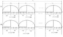
以下、図2を参照してこのΔtシフト部51の機能を説明する。まず、図2(A)について説明する。 Hereinafter, the function of the Δt shift unit 51 will be described with reference to FIG. First, FIG. 2A will be described.
図2(A)は従来のサンプリング周波数設定部50でサンプリングした例であり、図1のΔtシフト部51の効果を説明するために、対比の対象として示したものであり、本発明とは無関係である。 FIG. 2A shows an example of sampling by the conventional sampling frequency setting unit 50, which is shown as a comparison target in order to explain the effect of the Δt shift unit 51 of FIG. 1, and is not related to the present invention. It is.
ここで、図2(A)のサンプリング周期Ts1は例えば1msである。また、図2(A)では、全ての周期Tdにおいて、立ち上がりの直前を含み、同じタイミングでサンプリングされている。また、立ち上がりの前に6回サンプリングされ、立ち上がり後に5回サンプリングされている。このようにサンプリングされると、立ち上がり後のサンプリング回数が足りないため、量子化誤差が大きくなる。 Here, the sampling period Ts1 in FIG. 2A is, for example, 1 ms. In FIG. 2A, sampling is performed at the same timing in all the cycles Td, including immediately before the rise. Further, the sampling is performed 6 times before the rising edge and is sampled 5 times after the rising edge. When sampling is performed in this manner, the number of samplings after the rise is insufficient, resulting in a large quantization error.
次に、図2(B)を参照して図1のΔtシフト部の役割を説明する。図2(B)におけるサンプリング周期Tsは1.03msである。すなわち、Δtだけサンプリング周期を拡大している。 Next, the role of the Δt shift unit in FIG. 1 will be described with reference to FIG. The sampling period Ts in FIG. 2 (B) is 1.03 ms. That is, the sampling period is expanded by Δt.
図2(B)の一番左の周期Tdでは、立ち上がり前に6回、立ち上がり後に5回のサンプリングがされている。しかし、サンプリング周期Tsは図2(A)より広がっているため、次の周期Tdでは立ち上がり前に5回、立ち上がり後に6回のサンプリングがされている。 In the leftmost cycle Td in FIG. 2B, sampling is performed 6 times before rising and 5 times after rising. However, since the sampling period Ts is wider than that in FIG. 2A, sampling is performed 5 times before rising and 6 times after rising in the next period Td.
さらに、サンプリングのタイミングを各周期Tdで重ならないようにすることで、演算周期Tc内で取得する立ち上がり後のデータは全て異なる値となる。 Furthermore, by preventing the sampling timing from overlapping in each cycle Td, all the data after the rise acquired within the calculation cycle Tc have different values.
このため、本発明によれば、演算周期Tc内でサンプリングされたデータを平均化することにより量子化誤差を少なくできる。 For this reason, according to the present invention, the quantization error can be reduced by averaging the data sampled within the calculation cycle Tc.
なお、図2ではサンプリング周期Tsを1.03msにしたがこれに限られるものではなく、サンプリングのタイミングが各周期Tdで重ならなければ良い。例えばTsが0.97msでも1.01msでも良い。 In FIG. 2, the sampling period Ts is set to 1.03 ms. However, the present invention is not limited to this, and it is sufficient that the sampling timings do not overlap each other in each period Td. For example, Ts may be 0.97 ms or 1.01 ms.
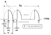
次に、図3を参照してサンプリングのタイミングを説明する。図2で説明したΔtシフト部の機能によってサンプリングのタイミングは次の様になる。 Next, sampling timing will be described with reference to FIG. The sampling timing is as follows by the function of the Δt shift unit described in FIG.
すなわち、A/D変換のサンプリング周期Ts101は、同一サンプリングデータ(TC)内における整流・電圧変換信号の各周期Tdにおいて、異なるタイミングでA/Dサンプリングを行う。つまり、図3を参照して説明すると「t1≠t3≠・・・≠t2N−1 , t2≠t4≠・・・≠t2N」となるようにサンプリングされる。 That is, the A / D conversion sampling cycle Ts101 performs A / D sampling at different timings in each cycle Td of the rectification / voltage conversion signal in the same sampling data (TC). That is, with reference to FIG. 3, sampling is performed so that “t1 ≠ t3 ≠... ≠ t2N−1, t2 ≠ t4 ≠.
このように、サンプリングのタイミングを微小にずらすΔtシフト部51を設けたので、低速のA/Dコンバータを用いても量子化誤差を少なくすることができる。 Thus, since the Δt shift unit 51 for slightly shifting the sampling timing is provided, the quantization error can be reduced even if a low-speed A / D converter is used.
なお、本発明はヒーター断線警報機能をオプションとして備えた温度調節計を例に説明したが、これに限られず、被測定波形が周期信号で、複数のサンプリングデータを用いて演算するものであれば本発明の範囲に含まれる。例えば、ヒーター断線警報機でも差し支えない。 Although the present invention has been described by taking a temperature controller equipped with an optional heater break alarm function as an example, the present invention is not limited to this, as long as the waveform to be measured is a periodic signal and is calculated using a plurality of sampling data. It is included in the scope of the present invention. For example, a heater break alarm can be used.
10 CT
20 整流・電圧変換回路
30 A/D変換部
31 アナログ信号入力部
32 信号変換部
33 デジタル信号出力部
40 演算部
41 温調計回路
50 サンプリング周波数設定部
51 Δtシフト部
10 CT
20 A rectification / voltage conversion circuit 30 A / D conversion unit 31 Analog signal input unit 32 Signal conversion unit 33 Digital signal output unit 40 Calculation unit 41 Temperature controller circuit 50 Sampling frequency setting unit 51 Δt shift unit
Claims (2)
前記整流・電圧変換信号の周期≠サンプリング周期×M(自然数)となるタイミングでサンプリングを行う旨を前記A/D変換部に出力するサンプリング周波数設定部を備えたことを特徴とする温度調節計。 A rectification / voltage conversion circuit for converting a heater current, which is a periodic signal transformed by a non-contact current sensor, into a voltage, and A / D conversion of the rectification / voltage conversion signal output from the rectification / voltage conversion circuit. In a temperature controller that includes an A / D converter and adjusts the temperature of a controlled object to a target value,
A temperature controller comprising: a sampling frequency setting unit that outputs to the A / D conversion unit that sampling is performed at a timing such that the cycle of the rectification / voltage conversion signal ≠ sampling cycle × M (natural number).
サンプリングのタイミングが前記整流・電圧変換信号の各周期で重ならないようにサンプリングを行う旨を前記A/D変換部に出力するサンプリング周波数設定部を備えたことを特徴とする温度調節計。 A rectification / voltage conversion circuit for converting a heater current, which is a periodic signal transformed by a non-contact current sensor, into a voltage, and A / D conversion of the rectification / voltage conversion signal output from the rectification / voltage conversion circuit. In a temperature controller that includes an A / D converter and adjusts the temperature of a controlled object to a target value,
A temperature controller comprising: a sampling frequency setting unit that outputs to the A / D conversion unit that sampling is performed so that sampling timing does not overlap in each cycle of the rectification / voltage conversion signal.
Priority Applications (1)
| Application Number | Priority Date | Filing Date | Title |
|---|---|---|---|
| JP2008229766A JP2010068024A (en) | 2008-09-08 | 2008-09-08 | Thermoregulator |
Applications Claiming Priority (1)
| Application Number | Priority Date | Filing Date | Title |
|---|---|---|---|
| JP2008229766A JP2010068024A (en) | 2008-09-08 | 2008-09-08 | Thermoregulator |
Publications (1)
| Publication Number | Publication Date |
|---|---|
| JP2010068024A true JP2010068024A (en) | 2010-03-25 |
Family
ID=42193260
Family Applications (1)
| Application Number | Title | Priority Date | Filing Date |
|---|---|---|---|
| JP2008229766A Pending JP2010068024A (en) | 2008-09-08 | 2008-09-08 | Thermoregulator |
Country Status (1)
| Country | Link |
|---|---|
| JP (1) | JP2010068024A (en) |
Cited By (2)
| Publication number | Priority date | Publication date | Assignee | Title |
|---|---|---|---|---|
| CN106091714A (en) * | 2015-12-04 | 2016-11-09 | 韩山师范学院 | A kind of kiln monitoring system |
| CN106595769A (en) * | 2016-12-23 | 2017-04-26 | 江苏宏宝工具有限公司 | Detection system with big data technology |
Citations (7)
| Publication number | Priority date | Publication date | Assignee | Title |
|---|---|---|---|---|
| JPS59152828U (en) * | 1983-03-28 | 1984-10-13 | アルプス電気株式会社 | sampling processing equipment |
| JPS6171499A (en) * | 1984-09-14 | 1986-04-12 | Hitachi Ltd | Data sampling method |
| JPS61252718A (en) * | 1985-05-02 | 1986-11-10 | Hitachi Ltd | Test system of analog-digital converter |
| JPH01304367A (en) * | 1988-06-01 | 1989-12-07 | Anritsu Corp | Waveform measuring instrument |
| JPH034621A (en) * | 1989-06-01 | 1991-01-10 | Gifu Univ | Method and device for sampling |
| JPH11355141A (en) * | 1998-06-10 | 1999-12-24 | Advantest Corp | Sampling digitizer |
| JP2005038241A (en) * | 2003-07-16 | 2005-02-10 | Omron Corp | Thermoregulator |
-
2008
- 2008-09-08 JP JP2008229766A patent/JP2010068024A/en active Pending
Patent Citations (7)
| Publication number | Priority date | Publication date | Assignee | Title |
|---|---|---|---|---|
| JPS59152828U (en) * | 1983-03-28 | 1984-10-13 | アルプス電気株式会社 | sampling processing equipment |
| JPS6171499A (en) * | 1984-09-14 | 1986-04-12 | Hitachi Ltd | Data sampling method |
| JPS61252718A (en) * | 1985-05-02 | 1986-11-10 | Hitachi Ltd | Test system of analog-digital converter |
| JPH01304367A (en) * | 1988-06-01 | 1989-12-07 | Anritsu Corp | Waveform measuring instrument |
| JPH034621A (en) * | 1989-06-01 | 1991-01-10 | Gifu Univ | Method and device for sampling |
| JPH11355141A (en) * | 1998-06-10 | 1999-12-24 | Advantest Corp | Sampling digitizer |
| JP2005038241A (en) * | 2003-07-16 | 2005-02-10 | Omron Corp | Thermoregulator |
Cited By (2)
| Publication number | Priority date | Publication date | Assignee | Title |
|---|---|---|---|---|
| CN106091714A (en) * | 2015-12-04 | 2016-11-09 | 韩山师范学院 | A kind of kiln monitoring system |
| CN106595769A (en) * | 2016-12-23 | 2017-04-26 | 江苏宏宝工具有限公司 | Detection system with big data technology |
Similar Documents
| Publication | Publication Date | Title |
|---|---|---|
| JP2009213228A (en) | Dc converter | |
| JP2003259629A (en) | Control circuit for switching power unit, and switching power unit using it | |
| JP6518793B2 (en) | POWER LINE COMMUNICATION DEVICE, AND ELECTRONIC CONTROL DEVICE PROVIDED WITH POWER LINE COMMUNICATION DEVICE | |
| CN105144587A (en) | Efficient time-interleaved analog-to-digital converter | |
| JP2008092670A (en) | Pwm signal generating circuit and power supply device equipped with the same | |
| WO2015127824A1 (en) | Double-loop control circuit of phase-shift full-bridge synchronous rectification circuit | |
| JP5989239B2 (en) | Signal processing device | |
| JP2010068024A (en) | Thermoregulator | |
| JP5578861B2 (en) | Switching power supply circuit | |
| JP2015142420A (en) | Control device for switching power source | |
| TW202029622A (en) | Multi-channel power system and phase shift controlling method thereof | |
| US20110181369A1 (en) | Digital pulse width modulation device | |
| JP4730435B2 (en) | PWM inverter device | |
| JP6488710B2 (en) | Slave for communication | |
| JP2006258698A (en) | Zero cross detection circuit | |
| CN107960142B (en) | Apparatus and method for processing inductor current | |
| JP2011053108A (en) | Reverse phase/phase interruption detecting device | |
| TW201545448A (en) | Over-current protecting circuit and method for providing over-current protecting reference signal | |
| JP2008131721A (en) | Switching power supply device | |
| JPWO2009060806A1 (en) | Power conversion circuit control device | |
| JP2008029107A (en) | Sine wave rms value detector and sine wave power supply device using the same | |
| JP2007166865A (en) | Switching power supply circuit | |
| JP2015133631A (en) | Analog-digital converter | |
| JP2005328585A (en) | Overcurrent limit circuit of current mode step-down switching regulator | |
| JP5881775B2 (en) | Power converter |
Legal Events
| Date | Code | Title | Description |
|---|---|---|---|
| A621 | Written request for application examination |
Free format text: JAPANESE INTERMEDIATE CODE: A621 Effective date: 20110324 |
|
| A977 | Report on retrieval |
Free format text: JAPANESE INTERMEDIATE CODE: A971007 Effective date: 20120820 |
|
| A131 | Notification of reasons for refusal |
Effective date: 20120823 Free format text: JAPANESE INTERMEDIATE CODE: A131 |
|
| A521 | Written amendment |
Free format text: JAPANESE INTERMEDIATE CODE: A523 Effective date: 20121018 |
|
| A02 | Decision of refusal |
Free format text: JAPANESE INTERMEDIATE CODE: A02 Effective date: 20121107 |