JP2010066021A - Electrostatic capacitance type proximity sensor - Google Patents
Electrostatic capacitance type proximity sensor Download PDFInfo
- Publication number
- JP2010066021A JP2010066021A JP2008230099A JP2008230099A JP2010066021A JP 2010066021 A JP2010066021 A JP 2010066021A JP 2008230099 A JP2008230099 A JP 2008230099A JP 2008230099 A JP2008230099 A JP 2008230099A JP 2010066021 A JP2010066021 A JP 2010066021A
- Authority
- JP
- Japan
- Prior art keywords
- change
- electrode
- voltage
- current
- frequency
- Prior art date
- Legal status (The legal status is an assumption and is not a legal conclusion. Google has not performed a legal analysis and makes no representation as to the accuracy of the status listed.)
- Pending
Links
Images


Abstract
Description
本発明は、静電容量の変化に基づいて人体などの接近を検出する近接センサに関する。 The present invention relates to a proximity sensor that detects the approach of a human body or the like based on a change in capacitance.
静電容量型近接センサは、電極と電気回路を備えている。
電極は、2枚の平板状の電極を並列して対面している。両電極は、コンデンサを構成している。また、電極と大地は、コンデンサを構成している。電極に検出対象物の人体などの接地体が接近すると、両電極間の静電容量と、電極と大地間の静電容量が変化する。
電気回路は、静電容量の変化を電流又は電圧の変化に変換し、電圧又は電流の変化量に基づいて検出対象物の接近を検出する。
The capacitive proximity sensor includes an electrode and an electric circuit.
The electrodes face each other in parallel with two flat electrodes. Both electrodes constitute a capacitor. The electrode and the ground constitute a capacitor. When a grounding body such as a human body of the detection target approaches the electrode, the capacitance between both electrodes and the capacitance between the electrode and the ground change.
The electric circuit converts a change in capacitance into a change in current or voltage, and detects the approach of the detection object based on the amount of change in voltage or current.
[課 題]
静電容量型近接センサは、機械、器具や建造物に組み込まれて使用される。電極の前側には、機械、器具や建造物のパネル、カバーや壁などの部材が位置することがある。静電容量型近接センサは、前側に部材が存在すると、前側の部材の表面に近付いて来る人体などの検出対象物を、前側の部材の裏面側で検出することになる。
この場合、静電容量型近接センサは、前側部材の表面からの検出可能距離、前側の検出距離が短い。前側部材の前側の検出距離は、長いことが望まれる。また、誤作動が少ないことが望まれる。
[Task]
Capacitive proximity sensors are used by being incorporated in machines, instruments and buildings. On the front side of the electrode, members such as a machine, an instrument or a panel of a building, a cover or a wall may be located. When a member is present on the front side, the capacitive proximity sensor detects a detection target such as a human body approaching the surface of the front member on the back side of the front member.
In this case, the capacitive proximity sensor has a short detectable distance from the surface of the front member and a short detection distance on the front side. It is desirable that the detection distance on the front side of the front member is long. Moreover, it is desired that there are few malfunctions.
[課題を解決するための着想]
静電容量型近接センサの前側に位置することになる部材は、材質が合成樹脂、陶器、ガラスや紙などであり、誘電体である。このような誘電体は、誘電率が空気より大きい。電極の前側に、誘電体の部材が存在すると、部材が存在せずに空気がある場合とは、両電極間の静電容量と、電極と大地間の静電容量が異なる。そこで、静電容量型近接センサは、前側に誘電体の部材が存在することを前提に設計して設定することにした。
[Idea for solving problems]
A member to be positioned on the front side of the capacitive proximity sensor is made of a synthetic resin, earthenware, glass, paper, or the like, and is a dielectric. Such a dielectric has a dielectric constant greater than that of air. When a dielectric member is present on the front side of the electrode, the capacitance between the two electrodes and the capacitance between the electrode and the ground are different from the case where there is air without the member. Therefore, the capacitive proximity sensor is designed and set on the assumption that a dielectric member exists on the front side.
また、静電容量型近接センサは、前側に誘電体の部材が存在すると、存在しない場合に比較して、検出対象物の電極への最接近距離が長くなり、検出対象物の接近による静電容量の変化量が減少する。電気回路は、検出対象物の接近による電圧又は電流の変化量が減少する。この変化量が減少すると、検出距離が短くなる。そこで、電気回路は、静電容量の小さな変化で電圧又は電流の変化が大きくなる回路、直列共振回路にすることにした。 In addition, in the capacitive proximity sensor, when a dielectric member is present on the front side, the closest approach distance to the electrode of the detection target is longer than when there is no dielectric member, and electrostatic capacitance due to the approach of the detection target is increased. The amount of change in capacity decreases. In the electric circuit, the amount of change in voltage or current due to the approach of the detection object decreases. When the amount of change decreases, the detection distance becomes shorter. In view of this, the electric circuit is a series resonance circuit in which a change in voltage or current increases with a small change in capacitance.
[課題の解決原理(図1〜図3参照)]
実験例の静電容量型近接センサに基づいて説明する。この静電容量型近接センサは、電極に一対の電極を用い、電気回路に直列共振回路を用いる。
[Solution principle of the problem (see FIGS. 1 to 3)]
A description will be given based on the capacitive proximity sensor of the experimental example. This capacitive proximity sensor uses a pair of electrodes as electrodes and a series resonance circuit as an electric circuit.
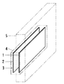
電極は、図1に示すように、一対の平板状の金属板1、2にし、前側電極1と後側電極2を並列して対面している。前後の電極1、2は、コンデンサ3を構成している。両電極1、2は、ケース4に内蔵している。ケース4は、前側を検出領域にしている。このケース4は、機械、器具や建造物に組み込まれたときに、前側に誘電体の部材5が位置することになる。
As shown in FIG. 1, the electrodes are a pair of
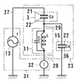
電気回路は、図2に示すように、コンデンサ3、コイル11、抵抗器12と発信源13を直列に接続している。コンデンサ3は、前側電極1をコイル11に、後側電極2を発信源13に接続している。発信源13と抵抗器12の間は、接地している。抵抗器12の両端の電圧Eを測定する測定器14を設けている。前側電極1と大地は、コンデンサ15を構成している。測定器14が測定する電圧Eの変化量ΔEに基づいて検出対象物の接近を検出する構成にしている。
As shown in FIG. 2, the electric circuit has a
コイル11は、自己インダクタンスLと巻き線間静電容量Cを有する。コンデンサ3は、静電容量Cdを有する。コンデンサ15は、静電容量Caを有する。抵抗器12は、抵抗Rを有する。発信源13は、発信交流の周波数fを変更可能にしている。
The
コイル11の自己インダクタンスLとコンデンサ3の静電容量Cd、コンデンサ15の静電容量Caで直列共振回路を構成している。なお、コイル11の自己インダクタンスLと巻き線間静電容量Cで並列共振回路を構成している。
A series resonance circuit is configured by the self-inductance L of the
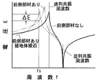
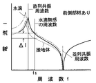
電圧Eと発信源13の発信交流の周波数fの関係は、図3に示した線図のようになる。直列共振の特性曲線は、山形になる。直列共振周波数は、並列共振周波数より低い。直列共振の特性曲線は、ケース4の前側に部材5がない状態で、図3の線図に実線で示すようになる。
The relationship between the voltage E and the frequency f of the transmission AC of the
ケース4の前側、電極1、2の前側に誘電体の部材5が存在すると、コンデンサ3の静電容量Cdが増加する。直列共振周波数が低くなる。また、抵抗器12を通過する電流、測定器14が測定する電圧Eが増加する。直列共振の特性曲線は、図3の線図に鎖線で示すようになる。山形の直列共振特性曲線は、周波数fの低い方に移動すると共に、電圧Eの高い方に移動する。
When the
ケース4の前側に部材5がある状態で、前側部材5の表面に人体などの接地体が接近すると、コンデンサ3の静電容量Cdが少し減少し、コンデンサ15の静電容量Caが多く増加する。直列共振周波数が低くなる。また、抵抗器12を通過する電流、測定器14が測定する電圧Eが減少する。直列共振の特性曲線は、図3の線図に破線で示すようになる。山形の直列共振特性曲線は、周波数fの低い方に移動すると共に、電圧Eの低い方に移動する。
When a grounding body such as a human body approaches the surface of the
そこで、発信源13の発信交流の周波数fは、図3の線図に示すように、前側部材5があって接地体が接近したときの直列共振周波数より少し低い周波数fsに設定する。すると、前側部材5の表面に接地体が接近したときに、電圧Eは、ΔE分変化する。その変化量ΔEは、大きい。検出距離が長くなる。
即ち、前側部材5があるときの直列共振特性曲線に基づいて、前側部材5がある状態で変化量ΔEが大きくなる周波数fsに設定する。
Therefore, the frequency f of the transmission AC of the
That is, based on the series resonance characteristic curve when the
また、水滴などの非検出対象物による誤作動を減らす場合、前側部材5があるときの直列共振特性曲線に基づいて、前側部材がある状態で非接地の水滴などの非検出対象物に対して無感になる周波数に設定する。
Moreover, when reducing malfunction due to non-detection objects such as water droplets, based on the series resonance characteristic curve when the
[検出能力の比較例(図4、図5参照)]
1)実験例
本発明の実験例は、図1〜図3に示して説明した静電容量型近接センサである。
[Comparison example of detection capability (see FIGS. 4 and 5)]
1) Experimental Example An experimental example of the present invention is the capacitive proximity sensor described with reference to FIGS.
2)比較例
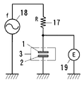
比較例の静電容量型近接センサは、実験例と同じケース4内蔵の電極1、2を用い、電気回路に直列共振回路に替えてRC回路を用いる。RC回路は、図4に示すように、電極1、2によるコンデンサ3、抵抗器17と発信源18を直列に接続している。コンデンサ3は、前側電極1を抵抗器17に、後側電極2を発信源18に接続している。発信源18と後側電極2の間は、接地している。コンデンサ3の両端の電圧Eを測定する測定器19を設けている。
2) Comparative Example The capacitive proximity sensor of the comparative example uses the
電圧Eと発信源18の発信交流の周波数fの関係は、図5に示した線図のようになる。電圧Eは、周波数fが特定の周波数より低い領域でほぼ一定になり、高い領域で周波数の増加に従って減少する。特性曲線は、横線と斜線を繋いだ折線になる。ケース4の前側に部材5がない状態で、特性曲線は、図5の線図に実線で示すようになる。
The relationship between the voltage E and the frequency f of the transmission AC of the
ケース4の前側、電極1、2の前側に誘電体の部材5が存在すると、コンデンサ3の静電容量が増加する。電圧Eは、周波数fの高い領域で減少する。特性曲線の斜線は、図5の線図に鎖線で示すように、電圧Eの低い方に移動する。
When the
前側部材5がある状態で、前側部材5の表面に人体などの接地体が接近すると、コンデンサ3の静電容量、前側電極1と大地間の静電容量が増加する。電圧Eは、周波数fの高い領域で減少する。特性曲線の斜線は、図5の線図に破線で示すように、電圧Eの低い方に更に移動する。
When a grounding body such as a human body approaches the surface of the
発信源18の発信交流の周波数fは、前側部材5がないとき、前側部材5があるとき、前側部材5があって接地体が接近したときに特性曲線の斜線部分になる周波数fsに設定する。
The frequency f of the transmission alternating current of the
3)実験の方法と結果
実験例と比較例の静電容量型近接センサにおいて、発信源13、18の発信交流は、正弦波交流にし、電圧を5Vにし、周波数fをそれぞれ所定の周波数fsに設定する。測定器14、19が測定する電圧Eを読み取る。
3) Experimental method and results In the capacitive proximity sensors of the experimental example and the comparative example, the transmission AC of the
3.1 前側部材なし
実験例では、ケース4の前側に部材5がない状態にし、その状態に適した周波数fsに設定する。電圧Eは、ケース4の前側の検出領域に人の手がないと、3Vになる。ケース4の前面に人の手が接触すると、2.9V変化する。変化量ΔEは、2.9Vである。人の手がケース4の前面に近付いて来る際、変化量ΔEが0.1Vになるときの、ケース4の前面からの手の距離は、85mm位になる。
3.1 No front member In the experimental example, the
比較例では、ケース4の前側に部材5がない状態にする。電圧Eは、ケース4の前側の検出領域に人の手がないと、2.7Vになる。ケース4の前面に人の手が接触すると、1.7V変化する。変化量ΔEは、1.7Vである。変化量ΔEが0.1Vになるときの、ケース4の前面からの手の距離は、11mm位になる。
実験例は、比較例より、変化量ΔEが大きい。検出距離が長い。
In the comparative example, the
The experimental example has a larger change amount ΔE than the comparative example. Long detection distance.
3.2 アクリル板の前側部材
実験例では、ケース4の前面に前側部材5として厚さ3.6mmのアクリル板を重ねる。その状態に適した周波数fsに設定する。前側部材5の前側の検出領域に人の手がないときと、前側部材5の前面に人の手が接触したときの変化量ΔEは、2.3Vになる。変化量ΔEが0.1Vになるときの、前側部材5からの手の距離は、80mm位になる。
3.2 Front Member of Acrylic Plate In the experimental example, an acrylic plate having a thickness of 3.6 mm is stacked as the
比較例では、ケース4の前面に同じアクリル板5を重ねる。変化量ΔEは、0.15Vになる。変化量ΔEが0.1Vになるときの、前側部材5の前面からの手の距離は、3mm位になる。
実験例は、比較例より、変化量ΔEが大きい。検出距離が長い。検出能力が高い。
In the comparative example, the same
The experimental example has a larger change amount ΔE than the comparative example. Long detection distance. High detection capability.
3.3 ビニルシートの前側部材
実験例では、前側部材5を厚さ2mm、8mm又は14mmのビニルシートにする。その状態に適した周波数fsに設定する。変化量ΔEは、前側部材5の厚さが2mmのときに2.4Vになり、8mmのときに1.5Vに、14mmのときに1.2Vになる。変化量ΔEが0.1Vになるときの、前側部材5の前面からの手の距離は、前側部材5の厚さがいずれのときも、80mm位になる。
3.3 Front member of vinyl sheet In the experimental example, the
比較例では、前側部材5を同じビニルシートにする。変化量ΔEは、前側部材5の厚さが2mmのときに0.4Vになり、8mmのときに0.18Vに、14mmのときに0.11Vになる。変化量ΔEが0.1Vになるときの、前側部材5の前面からの手の距離は、前側部材5の厚さが2mmのときに5mm位になり、厚さ8mmのときに2mm位になる。
実験例は、比較例より、変化量ΔEが大きい。検出距離が長い。
In the comparative example, the
The experimental example has a larger change amount ΔE than the comparative example. Long detection distance.
3.4 タイルの前側部材
実験例では、前側部材5を厚さ5mm又は10mmのタイルにする。その状態に適した周波数fsに設定する。変化量ΔEは、前側部材5の厚さが5mmのときに1.8Vになり、10mmのときに1.5Vになる。変化量ΔEが0.1Vになるときの、前側部材5の前面からの手の距離は、前側部材5の厚さがいずれのときも、85mm位になる。
3.4 Front member of tile In the experimental example, the
比較例では、前側部材5を同じタイルにする。変化量ΔEは、前側部材5の厚さが5mmのときに0.18Vになり、10mmのときに0.13Vになる。
実験例は、比較例より、変化量ΔEが大きい。
In the comparative example, the
The experimental example has a larger change amount ΔE than the comparative example.
3.5 コピー用紙の前側部材
実験例では、前側部材5を30枚又は60枚の重ねたコピー用紙にする。その状態に適した周波数fsに設定する。変化量ΔEは、コピー用紙5の枚数が30枚のときに1.5Vになり、60枚のときに1.1Vになる。変化量ΔEが0.1Vになるときの、前側部材5の前面からの手の距離は、コピー用紙5の枚数がいずれのときも、70mm位になる。
3.5 Front member of copy paper In the experimental example, the
比較例では、前側部材5を同じコピー用紙にする。変化量ΔEは、コピー用紙5の枚数が30枚のときに0.22Vになり、60枚のときに0.09Vになる。
実験例は、比較例より、変化量ΔEが大きい。
In the comparative example, the
The experimental example has a larger change amount ΔE than the comparative example.
1)コンデンサを構成する電極に検出対象物の人体などの接地体が接近すると、静電容量が変化し、電気回路が検出対象物の接近を検出する静電容量型近接センサにおいて、
電極の前側に誘電体の前側部材が位置し、前側部材の表面に近付いて来る検出対象物を前側部材の裏面側で検出する構成にし、
電気回路は、電極によるコンデンサ、コイルと発信源を接続して直列共振回路を構成し、静電容量の変化を電流又は電圧の変化に変換し、電圧又は電流の変化量に基づいて検出対象物の接近を検出する構成にし、
発信源の発信交流の周波数は、前側部材があるときの直列共振特性曲線に基づいて、前側部材がある状態で電圧又は電流の変化量が大きくなる周波数に設定する構成にしたことを特徴とする。
2)コンデンサを構成する電極に検出対象物の人体などの接地体が接近すると、静電容量が変化し、電気回路が検出対象物の接近を検出する静電容量型近接センサにおいて、
電極の前側に誘電体の前側部材が位置し、前側部材の表面に近付いて来る検出対象物を前側部材の裏面側で検出する構成にし、
電気回路は、電極によるコンデンサ、コイルと発信源を接続して直列共振回路を構成し、静電容量の変化を電流又は電圧の変化に変換し、電圧又は電流の変化量に基づいて検出対象物の接近を検出する構成にし、
発信源の発信交流の周波数は、前側部材があるときの直列共振特性曲線に基づいて、前側部材がある状態で非接地の水滴などの非検出対象物に対して無感になる周波数に設定し、接地体の検出対象物が前側部材に接近すると、電圧又は電流が変化し、非接地の非検出対象物が前側部材に接近すると、電圧又は電流が変化しない、又は、ほとんど変化しない構成にしたことを特徴とする静電容量型近接センサ。
3)上記の静電容量型近接センサにおいて、
電極とコイル及び電極とコイルを接続した電線は、ケースに内蔵し、相対位置を固定したことを特徴とする。
1) When a grounded body such as a human body of a detection object approaches the electrode constituting the capacitor, the capacitance changes, and the electrostatic capacity type proximity sensor in which the electric circuit detects the approach of the detection object,
The front side member of the dielectric is positioned on the front side of the electrode, and the detection target approaching the surface of the front side member is detected on the back side of the front side member.
The electric circuit consists of a series resonant circuit by connecting capacitors and coils with electrodes and a transmission source, converting the change in capacitance into a change in current or voltage, and detecting the object based on the change in voltage or current To detect the approach of
Based on the series resonance characteristic curve when the front member is present, the frequency of the transmission alternating current of the transmission source is set to a frequency at which the amount of change in voltage or current increases with the front member. .
2) When a grounding body such as a human body of the detection object approaches the electrode constituting the capacitor, the capacitance changes, and the electrostatic capacity proximity sensor in which the electric circuit detects the approach of the detection object,
The front side member of the dielectric is positioned on the front side of the electrode, and the detection target approaching the surface of the front side member is detected on the back side of the front side member.
The electric circuit consists of a series resonant circuit by connecting capacitors and coils with electrodes and a transmission source, converting the change in capacitance into a change in current or voltage, and detecting the object based on the change in voltage or current To detect the approach of
Based on the series resonance characteristic curve when the front member is present, the frequency of the transmission alternating current of the transmission source is set to a frequency at which the front member is insensitive to non-detected objects such as non-grounded water droplets. When the detection object of the grounding body approaches the front member, the voltage or current changes, and when the non-detection non-detection object approaches the front member, the voltage or current does not change or hardly changes. A capacitive proximity sensor characterized by the above.
3) In the above capacitive proximity sensor,
The electrode and the coil and the electric wire connecting the electrode and the coil are built in the case, and the relative position is fixed.
電極の前側に誘電体の前側部材が位置し、前側部材の表面に近付いて来る検出対象物を前側部材の裏面側で検出する場合、前側部材の前側の検出距離を長くすることができる。また、誤作動を減らすことができる。 When the front member of the dielectric is positioned on the front side of the electrode and the detection target approaching the surface of the front member is detected on the back side of the front member, the detection distance on the front side of the front member can be increased. Moreover, malfunction can be reduced.
[第1例(図6〜図10参照)]
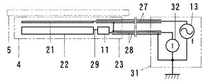
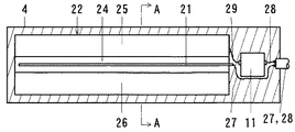
本例の静電容量型近接センサは、図6に示すように、一対の電極21、22などを内蔵した感知部23をシールド線27、28のケーブルで電気回路部31に接続している。
[First example (see FIGS. 6 to 10)]
In the capacitive proximity sensor of this example, as shown in FIG. 6, a
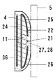
感知部23は、図6〜図9に示すように、一対の電極21、22とコイル11を内蔵している。一対の電極21、22は、前側の検出距離を長くするため、線状の前側電極21と面状の後側電極22にしている。
The
線状の前側電極21は、丸棒の金属線、電線にしている。
面状の後側電極22は、金属板を弓形状断面の筒形状に屈曲している。この後側電極22は、後側板24の上縁と下縁に上前側板25と下前側板26を連結している。後側板24は、長方形状の平板にしている。上前側板25と下前側板26は、それぞれ、長方形状の湾曲板にしている。上前側板25と下前側板26の間には、隙間を設けている。その隙間には、線状の前側電極21を配列している。線状の前側電極21は、面状の後側電極22に並列し、面状の後側電極22の後側板24、上前側板25と下前側板26に対して等距離に位置している。
The linear
The planar
電極21、22の片端側には、コイル11とケーブル27、28の一端を配置している。ケーブル27、28は、2本のシールド線27、28を束ねている。コイル11は、一端を面状の後側電極22に電線29で接続し、他端をシールド線28の心線に接続している。他のシールド線27は、心線を線状の前側電極21に接続している。両シールド線27、28は、被覆網線同士を接続している。
One end of the
線状の前側電極21、面状の後側電極22とコイル11及び電線29とケーブル27、28の一端は、合成樹脂液に没入し、合成樹脂液を硬化してケース4に成形している。ケース4は、合成樹脂成形品の電気絶縁体にし、弓形状断面の長方形板状にしている。
One end of the linear
ケース4は、機械、器具や建造物に組み込まれたときに、線状前側電極21側の前側に誘電体の部材5が位置する。前側部材5の前側は、検出領域にしている。
When the
線状の前側電極21と面状の後側電極22は、コンデンサ3を構成している。コンデンサ3は、静電容量Cdを有する。面状の後側電極22と大地は、コンデンサ15を構成している。コンデンサ15は、静電容量Caを有する。コイル11は、自己インダクタンスLと巻き線間静電容量Cを有する。
The linear
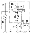
電気回路部31は、発信源13、測定器32とケーブル27、28の他端を内蔵している。発信源13は、一端を測定器32の一端に、他端をシールド線27の心線に接続している。測定器32の他端は、シールド線28の心線に接続している。両シールド線27、28の被覆網線は、発信源13と測定器32の間に接続している。発信源13と測定器32の間は、接地する構成にしている。発信源13は、発信交流の周波数fを変更可能にしている。測定器32は、コイル11と大地の間を流れる電流Iを測定する構成にしている。電気回路は、図9に示す通りである。これは、図2に示した電気回路に類似している。図2の電気回路中の抵抗器12は、電流Iの測定器32に置き換えている。測定器32が測定する電流Iの変化量ΔIに基づいて検出対象物の接近を検出する構成にしている。
The
コイル11の自己インダクタンスLとコンデンサ3の静電容量Cd、コンデンサ15の静電容量Caで直列共振回路を構成している。直列共振回路には、抵抗器12がない。直列共振の特性曲線は、山形が険しくなる。なお、コイル11の自己インダクタンスLと巻き線間静電容量Cで並列共振回路を構成している。
A series resonance circuit is configured by the self-inductance L of the
電流Iと発信源13の発信交流の周波数fの関係は、図10に示した線図のようになる。直列共振の特性曲線は、前側部材5の前側の検出領域に人体などの接地体がない初期状態で、図10の線図に実線で示すようになる。前側部材5の前面に人体などの接地体が接近した状態で、図10の線図に破線で示すようになる。発信源13の発信交流の周波数fは、前側部材5の前面に接地体が接近したときの直列共振周波数より少し低い周波数fsに設定する。前側部材5の表面に接地体が接近したときに、電流Iは、ΔI分変化する。変化量ΔIは、大きい。検出距離が長くなる。即ち、前側部材5があるときの直列共振特性曲線に基づいて、前側部材5がある状態で変化量ΔIが大きくなる周波数fsに設定する。
The relationship between the current I and the transmission frequency f of the
電極21、22、コイル11と電線29は、ケース4の電気絶縁体に埋没し、相対位置を固定している。それら付近の漂遊容量や漂遊インダクタンスが変化し難い。漂遊容量や漂遊インダクタンスの変化による直列共振特性のずれが発生し難い。
The
[第2例(図11〜図15参照)]
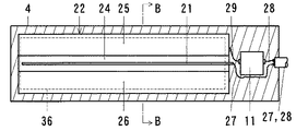
本例は、第1例の静電容量型近接センサを改良している。本例の静電容量型近接センサは、誤作動を減らすため、ケース4の後側の検出距離を短くする遮蔽電極36を設けている。また、ケース4の前側の部材5の表面に付着する水滴や雨滴などに対して無感にしている。
[Second Example (see FIGS. 11 to 15)]
In this example, the capacitive proximity sensor of the first example is improved. The capacitive proximity sensor of this example is provided with a shielding
ケース4は、図11〜図13に示すように、後側電極22の後側に遮蔽電極36を内蔵している。遮蔽電極36は、後側電極22の後側板24と同様に長方形平板の金属板にしている。後側板24と遮蔽電極36は、並列して対面している。遮蔽電極36は、シールド線27、28の被覆網線に接続している。接地する構成にしている。
As shown in FIGS. 11 to 13, the
遮蔽電極36と後側電極22は、コンデンサ15を構成している。コンデンサ15は、静電容量Caを有する。電気回路は、図14に示すように、第1例におけるのと同様に直列共振回路にしている。その他の構成は、第1例におけるのと同様である。
The
電流Iと発信源13の発信交流の周波数fの関係は、図15に示した線図のようになる。直列共振の特性曲線は、前側部材5の前側の検出領域に人体などの接地体や非接地の水滴や雨滴などがない初期状態で、図15の線図に実線で示すようになる。
The relationship between the current I and the frequency f of the transmission alternating current of the
非検出対象物の水滴や雨滴などが前側部材5の表面に付着して線状の前側電極21と面状の後側電極22の上前側板25又は下前側板26の間に接近すると、その非接地の水滴や雨滴などが前側電極21と後側電極22の間の誘電体として作用し、両電極21、22によるコンデンサ3の静電容量Cdが増加する。非接地の水滴や雨滴などの接近で、直列共振回路は、静電容量が増加する。直列共振周波数が低くなる。また、コンデンサ3、コイル11と測定器32の直列接続部は、インピーダンスが減少し、測定器32を通過する電流Iが増加する。直列共振の特性曲線は、図15の線図に鎖線で示すように、周波数fの低い方に移動すると共に、電流Iの高い方に移動する。
When water droplets or raindrops of a non-detection object adhere to the surface of the
図15の線図において、初期状態の直列共振周波数より高い周波数域で、実線で示す初期状態の特性曲線と鎖線で示す水滴接近時の特性曲線が交差する。その交差点の周波数fs付近では、水滴などの接近で電流Iが変化しない、又は、ほとんど変化しない。水滴などの接近に対して無感の周波数fsが存在する。そこで、発信源13は、発信交流の周波数fを水滴無感の周波数fsに設定する。即ち、前側部材5があるときの直列共振特性曲線に基づいて、前側部材5がある状態で水滴無感になる周波数fsに設定する。
In the diagram of FIG. 15, the characteristic curve in the initial state indicated by the solid line and the characteristic curve at the time of approaching the water droplet indicated by the chain line intersect at a frequency range higher than the series resonance frequency in the initial state. In the vicinity of the frequency fs at the intersection, the current I does not change or hardly changes due to the approach of a water drop or the like. There is a frequency fs that is insensitive to the approach of water drops. Therefore, the
すると、非検出対象物の水滴などが前側電極21と後側電極22の間に接近しても、測定器32が測定する電流Iの値が変化しない、又は、ほとんど変化しない。電気回路は、出力しない。非検出対象物の水滴などの接近による誤動作が発生しない。
Then, even if a water droplet or the like of the non-detection target approaches between the
前側部材5の前面に人体などの接地体が接近すると、コンデンサ3の静電容量Cdが少し減少し、コンデンサ15の静電容量Caが多く増加する。直列共振周波数が低くなる。また、測定器32を通過する電流Iが減少する。直列共振の特性曲線は、図15の線図に破線で示すように、周波数fの低い方に移動すると共に、電流Iの低い方に移動する。
When a grounding body such as a human body approaches the front surface of the
前側部材5の表面に人体などの接地体が接近したときに、測定器32が測定する電流Iは、ΔI分変化する。変化量ΔIは、大きい。検出距離が長くなる。
When a grounding body such as a human body approaches the surface of the
[変形例]
1)上記の実施形態において、線状の前側電極21は、断面形状が円形であるが、角形にする。
2)上記の実施形態において、面状の後側電極22は、弓形状断面の筒形状であるが、角筒形状、又は、その他の筒形状にする。
3)上記の実施形態において、面状の後側電極22は、1枚の板を屈曲しているが、複数枚の板にする。
[Modification]
1) In the above embodiment, the linear
2) In the above-described embodiment, the planar
3) In the above embodiment, the planar
本発明は、特定個所への人体の接近による機械器具の作動の開始又は停止、移動体と人体の接近や衝突の防止、危険個所への人体の接近の防止、立入禁止区域への人体の侵入の防止や、人体の所在確認などに利用される。 The present invention starts or stops the operation of a machine / equipment due to the approach of a human body to a specific location, prevents the approach and collision between a moving body and a human body, prevents the human body from approaching a dangerous location, and enters a restricted area. It is used for prevention of human beings and confirmation of human location.
1、2 平板状の金属板、電極
1 前側電極
2 後側電極
3、Cd コンデンサ、前側電極と後側電極によるコンデンサ、静電容量
4 ケース、電気絶縁体
5 部材、前側部材、誘電体
11、L、C コイル、自己インダクタンス、巻き線間静電容量
12、R 抵抗器、抵抗値
13、f、fs 発信源、発信交流の周波数、設定周波数
14 測定器、電圧の測定器
E 電圧、抵抗器両端の電圧
ΔE 電圧の変化量
15、Ca コンデンサ、前側電極と大地又は遮蔽電極によるコンデンサ、静電容量
17、R 比較例の抵抗器、抵抗値
18、f、fs 比較例の発信源、発信交流の周波数、設定周波数
19 比較例の測定器、電圧の測定器
21、22 電極
21 線状の前側電極、電線
22 面状の後側電極、屈曲金属板
23 感知部
24 後側電極の後側板
25 後側電極の上前側板
26 後側電極の下前側板
27、28 シールド線、ケーブル
29 電線
31 電気回路部
32 測定器、電流の測定器
I 電流、コイルを流れる電流
ΔI 電流の変化量
36 遮蔽電極
1, 2 flat metal plate,
Claims (3)
電極の前側に誘電体の前側部材が位置し、前側部材の表面に近付いて来る検出対象物を前側部材の裏面側で検出する構成にし、
電気回路は、電極によるコンデンサ、コイルと発信源を接続して直列共振回路を構成し、静電容量の変化を電流又は電圧の変化に変換し、電圧又は電流の変化量に基づいて検出対象物の接近を検出する構成にし、
発信源の発信交流の周波数は、前側部材があるときの直列共振特性曲線に基づいて、前側部材がある状態で電圧又は電流の変化量が大きくなる周波数に設定する構成にしたことを特徴とする静電容量型近接センサ。 When a grounding body such as a human body of the detection object approaches the electrode constituting the capacitor, the capacitance changes, and in the electrostatic capacitance type proximity sensor in which the electric circuit detects the approach of the detection object,
The front side member of the dielectric is positioned on the front side of the electrode, and the detection target approaching the surface of the front side member is detected on the back side of the front side member.
The electric circuit consists of a series resonant circuit by connecting capacitors and coils with electrodes and a transmission source, converting the change in capacitance into a change in current or voltage, and detecting the object based on the change in voltage or current To detect the approach of
Based on the series resonance characteristic curve when the front member is present, the frequency of the transmission alternating current of the transmission source is set to a frequency at which the amount of change in voltage or current increases with the front member. Capacitive proximity sensor.
電極の前側に誘電体の前側部材が位置し、前側部材の表面に近付いて来る検出対象物を前側部材の裏面側で検出する構成にし、
電気回路は、電極によるコンデンサ、コイルと発信源を接続して直列共振回路を構成し、静電容量の変化を電流又は電圧の変化に変換し、電圧又は電流の変化量に基づいて検出対象物の接近を検出する構成にし、
発信源の発信交流の周波数は、前側部材があるときの直列共振特性曲線に基づいて、前側部材がある状態で非接地の水滴などの非検出対象物に対して無感になる周波数に設定し、接地体の検出対象物が前側部材に接近すると、電圧又は電流が変化し、非接地の非検出対象物が前側部材に接近すると、電圧又は電流が変化しない、又は、ほとんど変化しない構成にしたことを特徴とする静電容量型近接センサ。 When a grounding body such as a human body of the detection object approaches the electrode constituting the capacitor, the capacitance changes, and in the electrostatic capacitance type proximity sensor in which the electric circuit detects the approach of the detection object,
The front side member of the dielectric is positioned on the front side of the electrode, and the detection target approaching the surface of the front side member is detected on the back side of the front side member.
The electric circuit consists of a series resonant circuit by connecting capacitors and coils with electrodes and a transmission source, converting the change in capacitance into a change in current or voltage, and detecting the object based on the change in voltage or current To detect the approach of
Based on the series resonance characteristic curve when the front member is present, the frequency of the transmission alternating current of the transmission source is set to a frequency at which the front member is insensitive to non-detected objects such as non-grounded water droplets. When the detection object of the grounding body approaches the front member, the voltage or current changes, and when the non-grounded non-detection object approaches the front member, the voltage or current does not change or hardly changes. A capacitive proximity sensor characterized by the above.
Priority Applications (1)
| Application Number | Priority Date | Filing Date | Title |
|---|---|---|---|
| JP2008230099A JP2010066021A (en) | 2008-09-08 | 2008-09-08 | Electrostatic capacitance type proximity sensor |
Applications Claiming Priority (1)
| Application Number | Priority Date | Filing Date | Title |
|---|---|---|---|
| JP2008230099A JP2010066021A (en) | 2008-09-08 | 2008-09-08 | Electrostatic capacitance type proximity sensor |
Publications (2)
| Publication Number | Publication Date |
|---|---|
| JP2010066021A true JP2010066021A (en) | 2010-03-25 |
| JP2010066021A5 JP2010066021A5 (en) | 2011-06-23 |
Family
ID=42191740
Family Applications (1)
| Application Number | Title | Priority Date | Filing Date |
|---|---|---|---|
| JP2008230099A Pending JP2010066021A (en) | 2008-09-08 | 2008-09-08 | Electrostatic capacitance type proximity sensor |
Country Status (1)
| Country | Link |
|---|---|
| JP (1) | JP2010066021A (en) |
Cited By (4)
| Publication number | Priority date | Publication date | Assignee | Title |
|---|---|---|---|---|
| JP2018081013A (en) * | 2016-11-17 | 2018-05-24 | 東京パーツ工業株式会社 | Capacitive proximity sensor and door handle device including the same |
| CN111201582A (en) * | 2017-11-10 | 2020-05-26 | 阿尔卑斯阿尔派株式会社 | Input device |
| CN114001692A (en) * | 2020-07-27 | 2022-02-01 | 长鑫存储技术有限公司 | Method for measuring shortest distance between capacitors and method for evaluating capacitor manufacturing process |
| US11933863B2 (en) | 2020-07-27 | 2024-03-19 | Changxin Memory Technologies, Inc. | Method for measuring shortest distance between capacitances and method for evaluating capacitance manufacture procedure |
Citations (7)
| Publication number | Priority date | Publication date | Assignee | Title |
|---|---|---|---|---|
| JPH0864365A (en) * | 1994-08-17 | 1996-03-08 | Seikosha Co Ltd | Object detecting device and illumination flickering device controlled by the object detecting device |
| JP2000177380A (en) * | 1998-12-14 | 2000-06-27 | Harness Syst Tech Res Ltd | Nipping detector |
| JP2001141836A (en) * | 1999-11-12 | 2001-05-25 | Sumitomo Chem Co Ltd | Human body detector |
| JP2002039708A (en) * | 2000-07-27 | 2002-02-06 | Aisin Seiki Co Ltd | Capacitance type proximity sensor |
| JP2006078422A (en) * | 2004-09-13 | 2006-03-23 | Mitsuba Corp | Proximity sensor, and insertion detector using same |
| JP2009222423A (en) * | 2008-03-13 | 2009-10-01 | Keiichi Nonogaki | Capacity-type proximity sensor |
| JP2009278319A (en) * | 2008-05-14 | 2009-11-26 | Keiichi Nonogaki | Capacitance proximity sensor |
-
2008
- 2008-09-08 JP JP2008230099A patent/JP2010066021A/en active Pending
Patent Citations (7)
| Publication number | Priority date | Publication date | Assignee | Title |
|---|---|---|---|---|
| JPH0864365A (en) * | 1994-08-17 | 1996-03-08 | Seikosha Co Ltd | Object detecting device and illumination flickering device controlled by the object detecting device |
| JP2000177380A (en) * | 1998-12-14 | 2000-06-27 | Harness Syst Tech Res Ltd | Nipping detector |
| JP2001141836A (en) * | 1999-11-12 | 2001-05-25 | Sumitomo Chem Co Ltd | Human body detector |
| JP2002039708A (en) * | 2000-07-27 | 2002-02-06 | Aisin Seiki Co Ltd | Capacitance type proximity sensor |
| JP2006078422A (en) * | 2004-09-13 | 2006-03-23 | Mitsuba Corp | Proximity sensor, and insertion detector using same |
| JP2009222423A (en) * | 2008-03-13 | 2009-10-01 | Keiichi Nonogaki | Capacity-type proximity sensor |
| JP2009278319A (en) * | 2008-05-14 | 2009-11-26 | Keiichi Nonogaki | Capacitance proximity sensor |
Cited By (6)
| Publication number | Priority date | Publication date | Assignee | Title |
|---|---|---|---|---|
| JP2018081013A (en) * | 2016-11-17 | 2018-05-24 | 東京パーツ工業株式会社 | Capacitive proximity sensor and door handle device including the same |
| CN111201582A (en) * | 2017-11-10 | 2020-05-26 | 阿尔卑斯阿尔派株式会社 | Input device |
| JPWO2019092953A1 (en) * | 2017-11-10 | 2020-10-22 | アルプスアルパイン株式会社 | Input device |
| CN114001692A (en) * | 2020-07-27 | 2022-02-01 | 长鑫存储技术有限公司 | Method for measuring shortest distance between capacitors and method for evaluating capacitor manufacturing process |
| CN114001692B (en) * | 2020-07-27 | 2023-04-07 | 长鑫存储技术有限公司 | Method for measuring shortest distance between capacitors and method for evaluating capacitor manufacturing process |
| US11933863B2 (en) | 2020-07-27 | 2024-03-19 | Changxin Memory Technologies, Inc. | Method for measuring shortest distance between capacitances and method for evaluating capacitance manufacture procedure |
Similar Documents
| Publication | Publication Date | Title |
|---|---|---|
| WO2011024306A1 (en) | Electrostatic capacity type proximity sensor | |
| JP5055172B2 (en) | Capacitive proximity sensor | |
| US8970523B2 (en) | Two-dimensional capacitive touch panel with single sensor layer | |
| TWI417777B (en) | Capacitive touch panel with high touching sensitivity | |
| KR101432353B1 (en) | Touch sensitive devices with composite electrodes | |
| EP2904478B1 (en) | Touch sensors and touch sensing methods | |
| KR102050444B1 (en) | Touch input system and method for detecting touch using the same | |
| TWI442293B (en) | Method and device for capacitive sensing | |
| CN102150109B (en) | Capacitive touch panel device of high-sensitivity digital system | |
| CN104718460B (en) | Electrode test apparatus | |
| CN103914172B (en) | Touch point detection circuit, inductance type touch screen and touch display device | |
| EP2972706B1 (en) | Electrostatic stylus | |
| JP5028552B2 (en) | Object detection device for detecting an object using electromagnetic induction | |
| EP2542952A1 (en) | A touch sensitive film and a touch sensing device | |
| US11281329B2 (en) | Device for detecting touch | |
| JP2010066021A (en) | Electrostatic capacitance type proximity sensor | |
| JP2009278319A (en) | Capacitance proximity sensor | |
| JP2007018839A (en) | Capacitive type proximity sensor | |
| JP6349748B2 (en) | Non-contact voltage measuring device | |
| WO2011111146A1 (en) | Capacitance type proximity sensor | |
| JP5102716B2 (en) | Capacitive proximity sensor | |
| CN102117157B (en) | Capacitance-type touch-control panel with high sensitivity | |
| KR20180045788A (en) | Touch input device | |
| JP4170112B2 (en) | Obstacle discrimination device for vehicle | |
| EP2274629B1 (en) | Measuring apparatus comprising adaptor component |
Legal Events
| Date | Code | Title | Description |
|---|---|---|---|
| A521 | Written amendment |
Free format text: JAPANESE INTERMEDIATE CODE: A523 Effective date: 20110427 |
|
| A621 | Written request for application examination |
Free format text: JAPANESE INTERMEDIATE CODE: A621 Effective date: 20110427 |
|
| A977 | Report on retrieval |
Effective date: 20120827 Free format text: JAPANESE INTERMEDIATE CODE: A971007 |
|
| A131 | Notification of reasons for refusal |
Free format text: JAPANESE INTERMEDIATE CODE: A131 Effective date: 20120911 |
|
| A02 | Decision of refusal |
Free format text: JAPANESE INTERMEDIATE CODE: A02 Effective date: 20130319 |