JP5028552B2 - Object detection device for detecting an object using electromagnetic induction - Google Patents
Object detection device for detecting an object using electromagnetic induction Download PDFInfo
- Publication number
- JP5028552B2 JP5028552B2 JP2008522287A JP2008522287A JP5028552B2 JP 5028552 B2 JP5028552 B2 JP 5028552B2 JP 2008522287 A JP2008522287 A JP 2008522287A JP 2008522287 A JP2008522287 A JP 2008522287A JP 5028552 B2 JP5028552 B2 JP 5028552B2
- Authority
- JP
- Japan
- Prior art keywords
- loop wiring
- loop
- wiring group
- group
- wirings
- Prior art date
- Legal status (The legal status is an assumption and is not a legal conclusion. Google has not performed a legal analysis and makes no representation as to the accuracy of the status listed.)
- Expired - Fee Related
Links
Images


Classifications
-
- G—PHYSICS
- G01—MEASURING; TESTING
- G01B—MEASURING LENGTH, THICKNESS OR SIMILAR LINEAR DIMENSIONS; MEASURING ANGLES; MEASURING AREAS; MEASURING IRREGULARITIES OF SURFACES OR CONTOURS
- G01B7/00—Measuring arrangements characterised by the use of electric or magnetic techniques
- G01B7/003—Measuring arrangements characterised by the use of electric or magnetic techniques for measuring position, not involving coordinate determination
-
- G—PHYSICS
- G01—MEASURING; TESTING
- G01B—MEASURING LENGTH, THICKNESS OR SIMILAR LINEAR DIMENSIONS; MEASURING ANGLES; MEASURING AREAS; MEASURING IRREGULARITIES OF SURFACES OR CONTOURS
- G01B7/00—Measuring arrangements characterised by the use of electric or magnetic techniques
- G01B7/02—Measuring arrangements characterised by the use of electric or magnetic techniques for measuring length, width or thickness
- G01B7/023—Measuring arrangements characterised by the use of electric or magnetic techniques for measuring length, width or thickness for measuring distance between sensor and object
-
- G—PHYSICS
- G01—MEASURING; TESTING
- G01B—MEASURING LENGTH, THICKNESS OR SIMILAR LINEAR DIMENSIONS; MEASURING ANGLES; MEASURING AREAS; MEASURING IRREGULARITIES OF SURFACES OR CONTOURS
- G01B7/00—Measuring arrangements characterised by the use of electric or magnetic techniques
- G01B7/28—Measuring arrangements characterised by the use of electric or magnetic techniques for measuring contours or curvatures
-
- G—PHYSICS
- G01—MEASURING; TESTING
- G01D—MEASURING NOT SPECIALLY ADAPTED FOR A SPECIFIC VARIABLE; ARRANGEMENTS FOR MEASURING TWO OR MORE VARIABLES NOT COVERED IN A SINGLE OTHER SUBCLASS; TARIFF METERING APPARATUS; MEASURING OR TESTING NOT OTHERWISE PROVIDED FOR
- G01D5/00—Mechanical means for transferring the output of a sensing member; Means for converting the output of a sensing member to another variable where the form or nature of the sensing member does not constrain the means for converting; Transducers not specially adapted for a specific variable
- G01D5/12—Mechanical means for transferring the output of a sensing member; Means for converting the output of a sensing member to another variable where the form or nature of the sensing member does not constrain the means for converting; Transducers not specially adapted for a specific variable using electric or magnetic means
- G01D5/14—Mechanical means for transferring the output of a sensing member; Means for converting the output of a sensing member to another variable where the form or nature of the sensing member does not constrain the means for converting; Transducers not specially adapted for a specific variable using electric or magnetic means influencing the magnitude of a current or voltage
- G01D5/20—Mechanical means for transferring the output of a sensing member; Means for converting the output of a sensing member to another variable where the form or nature of the sensing member does not constrain the means for converting; Transducers not specially adapted for a specific variable using electric or magnetic means influencing the magnitude of a current or voltage by varying inductance, e.g. by a movable armature
- G01D5/204—Mechanical means for transferring the output of a sensing member; Means for converting the output of a sensing member to another variable where the form or nature of the sensing member does not constrain the means for converting; Transducers not specially adapted for a specific variable using electric or magnetic means influencing the magnitude of a current or voltage by varying inductance, e.g. by a movable armature by influencing the mutual induction between two or more coils
-
- G—PHYSICS
- G01—MEASURING; TESTING
- G01R—MEASURING ELECTRIC VARIABLES; MEASURING MAGNETIC VARIABLES
- G01R27/00—Arrangements for measuring resistance, reactance, impedance, or electric characteristics derived therefrom
- G01R27/02—Measuring real or complex resistance, reactance, impedance, or other two-pole characteristics derived therefrom, e.g. time constant
- G01R27/26—Measuring inductance or capacitance; Measuring quality factor, e.g. by using the resonance method; Measuring loss factor; Measuring dielectric constants ; Measuring impedance or related variables
- G01R27/2611—Measuring inductance
-
- G—PHYSICS
- G01—MEASURING; TESTING
- G01V—GEOPHYSICS; GRAVITATIONAL MEASUREMENTS; DETECTING MASSES OR OBJECTS; TAGS
- G01V3/00—Electric or magnetic prospecting or detecting; Measuring magnetic field characteristics of the earth, e.g. declination, deviation
- G01V3/08—Electric or magnetic prospecting or detecting; Measuring magnetic field characteristics of the earth, e.g. declination, deviation operating with magnetic or electric fields produced or modified by objects or geological structures or by detecting devices
- G01V3/10—Electric or magnetic prospecting or detecting; Measuring magnetic field characteristics of the earth, e.g. declination, deviation operating with magnetic or electric fields produced or modified by objects or geological structures or by detecting devices using induction coils
- G01V3/101—Electric or magnetic prospecting or detecting; Measuring magnetic field characteristics of the earth, e.g. declination, deviation operating with magnetic or electric fields produced or modified by objects or geological structures or by detecting devices using induction coils by measuring the impedance of the search coil; by measuring features of a resonant circuit comprising the search coil
- G01V3/102—Electric or magnetic prospecting or detecting; Measuring magnetic field characteristics of the earth, e.g. declination, deviation operating with magnetic or electric fields produced or modified by objects or geological structures or by detecting devices using induction coils by measuring the impedance of the search coil; by measuring features of a resonant circuit comprising the search coil by measuring amplitude
-
- G—PHYSICS
- G06—COMPUTING OR CALCULATING; COUNTING
- G06F—ELECTRIC DIGITAL DATA PROCESSING
- G06F3/00—Input arrangements for transferring data to be processed into a form capable of being handled by the computer; Output arrangements for transferring data from processing unit to output unit, e.g. interface arrangements
- G06F3/01—Input arrangements or combined input and output arrangements for interaction between user and computer
- G06F3/03—Arrangements for converting the position or the displacement of a member into a coded form
- G06F3/041—Digitisers, e.g. for touch screens or touch pads, characterised by the transducing means
- G06F3/046—Digitisers, e.g. for touch screens or touch pads, characterised by the transducing means by electromagnetic means
Landscapes
- Physics & Mathematics (AREA)
- Engineering & Computer Science (AREA)
- General Physics & Mathematics (AREA)
- Theoretical Computer Science (AREA)
- General Engineering & Computer Science (AREA)
- Electromagnetism (AREA)
- Human Computer Interaction (AREA)
- Remote Sensing (AREA)
- Life Sciences & Earth Sciences (AREA)
- Environmental & Geological Engineering (AREA)
- Geology (AREA)
- General Life Sciences & Earth Sciences (AREA)
- Geophysics (AREA)
- Measurement Of Length, Angles, Or The Like Using Electric Or Magnetic Means (AREA)
- Geophysics And Detection Of Objects (AREA)
Description
本発明は物体を検出する物体検出装置に関し、特に、電磁誘導を用いて導電体又は磁性体からなる被測定物体の形状や被測定物体からの距離を検出する物体検出装置に関する。 The present invention relates to an object detection apparatus that detects an object, and more particularly to an object detection apparatus that detects the shape of a measured object made of a conductor or a magnetic material and the distance from the measured object using electromagnetic induction.
従来の電磁誘導を用いて導電体又は磁性体等からなる物体を検出するものとしては、例えば特許文献1に開示の技術がある。これは、複数のセンスコイルを検出面上に二次元配置して、導電体又は磁性体からなる位置指示器による指示位置をセンスコイルのインダクタンスの変化を基に読み取るものである。また、特許文献2に開示の技術は、コイル間にクッション材を設けたセンサ部を複数マトリックス状に配置し、センサ部にかかる圧力分布を電磁結合の変化を基に検出するものである。
As a technique for detecting an object made of a conductor or a magnetic material using conventional electromagnetic induction, for example, there is a technique disclosed in Patent Document 1. In this method, a plurality of sense coils are two-dimensionally arranged on the detection surface, and a position indicated by a position indicator made of a conductor or a magnetic material is read based on a change in inductance of the sense coil. In the technique disclosed in
しかしながら、従来の導電体又は磁性体からなる物体の検出装置には、以下のような問題があった。すなわち、例えば特許文献1の技術は、導電体又は磁性体からなる物体のみを検出するものであり、これを例えば指等の非導電体・非磁性体の指示位置を検出するような構造とすることはできなかった。また、センスコイルの数と同数の切替器が必要となるため、物体の形状を検出しようとした場合には多数のセンスコイルと切替器が必要となるので、非常に高価なものとなっていた。 However, the conventional object detection device made of a conductor or magnetic material has the following problems. That is, for example, the technique of Patent Document 1 detects only an object made of a conductor or a magnetic material, and has a structure for detecting the indicated position of a non-conductor / non-magnetic material such as a finger. I couldn't. Further, since the same number of switches as the number of sense coils are required, when detecting the shape of an object, a large number of sense coils and switches are required, which is very expensive. .
また、特許文献2の技術では、導電体又は磁性体からなる物体をセンサ上に載せると、本来は圧力により誘導電流又は誘導電圧は増加しなければならないにも関わらず、導電体又は磁性体の影響で減衰又は増加してしまう。このため、測定できるのは非導電体・非磁性体に限られていた。
In the technique of
本発明は、斯かる実情に鑑み、導電体又は磁性体からなる物体の形状や物体からの距離が安価に且つ安定して検出可能で、さらに指等の非導電体・非磁性体の物体の指示位置検出も可能となる物体検出装置を提供しようとするものである。 In view of such circumstances, the present invention can detect a shape of an object made of a conductor or a magnetic material and a distance from the object at a low cost and in addition to a non-conductor / non-magnetic object such as a finger. An object detection apparatus capable of detecting a designated position is provided.
上述した本発明の目的を達成するために、本発明による物体検出装置は、複数のコイル状部分をそれぞれ有する複数の第1ループ配線が同一平面上に平行に配置される第1ループ配線群と、複数のコイル状部分をそれぞれ有する複数の第2ループ配線が同一平面上に平行に配置される第2ループ配線群であって、該第2ループ配線群は第1ループ配線群と平行であり、複数の第2ループ配線は複数の第1ループ配線とそれぞれ直交する方向に配置される、第2ループ配線群と、第1ループ配線群と第2ループ配線群との間の距離を一定に保つスペーサ手段と、第1ループ配線と第2ループ配線が直交するそれぞれの位置にコイル状部分が配置されることで第1ループ配線と第2ループ配線が電磁結合するように構成される複数の電磁結合部と、第1ループ配線群又は第2ループ配線群の一方に接続され、該ループ配線群を駆動する駆動手段と、第1ループ配線群又は第2ループ配線群の他方に接続され、該ループ配線群から電磁結合部の電磁結合の変化を検出する検出手段と、を具備するものである。 In order to achieve the above-described object of the present invention, an object detection apparatus according to the present invention includes a first loop wiring group in which a plurality of first loop wirings each having a plurality of coiled portions are arranged in parallel on the same plane. A second loop wiring group in which a plurality of second loop wirings each having a plurality of coil-like portions are arranged in parallel on the same plane, the second loop wiring group being parallel to the first loop wiring group The plurality of second loop wirings are arranged in directions orthogonal to the plurality of first loop wirings, respectively, and the distance between the second loop wiring group and the first loop wiring group and the second loop wiring group is constant. A plurality of spacers configured to electromagnetically couple the first loop wiring and the second loop wiring by disposing a coil-shaped portion at each position where the first loop wiring and the second loop wiring are orthogonal to each other; With electromagnetic coupling Connected to one of the first loop wiring group or the second loop wiring group and connected to the driving means for driving the loop wiring group and the other of the first loop wiring group or the second loop wiring group, and from the loop wiring group Detecting means for detecting a change in electromagnetic coupling of the electromagnetic coupling unit.
ここで、第1ループ配線のコイル状部分の大きさと第2ループ配線のコイル状部分の大きさが、それぞれ異なるものであっても良い。 Here, the size of the coiled portion of the first loop wiring may be different from the size of the coiled portion of the second loop wiring.
また、物体検出装置は、複数のコイル状部分をそれぞれ有する複数の第1ループ配線が同一平面上に平行に配置される第1ループ配線群と、複数の直線状の第2ループ配線が同一平面上に平行に配置される第2ループ配線群であって、該第2ループ配線群は第1ループ配線群と平行であり、複数の第2ループ配線は複数の第1ループ配線とそれぞれ直交する方向に配置される、第2ループ配線群と、第1ループ配線群と第2ループ配線群との間の距離を一定に保つスペーサ手段と、第1ループ配線と第2ループ配線が直交するそれぞれの位置にコイル状部分が配置されることで第1ループ配線と第2ループ配線が電磁結合するように構成される複数の電磁結合部と、第1ループ配線群又は第2ループ配線群の一方に接続され、該ループ配線群を駆動する駆動手段と、第1ループ配線群又は第2ループ配線群の他方に接続され、該ループ配線群から電磁結合部の電磁結合の変化を検出する検出手段と、を具備するものであっても良い。 Further, the object detection device includes a first loop wiring group in which a plurality of first loop wirings each having a plurality of coil-shaped portions are arranged in parallel on the same plane, and a plurality of linear second loop wirings on the same plane. A second loop wiring group arranged in parallel above, wherein the second loop wiring group is parallel to the first loop wiring group, and the plurality of second loop wirings are orthogonal to the plurality of first loop wirings, respectively. The second loop wiring group, the spacer means for maintaining a constant distance between the first loop wiring group and the second loop wiring group, and the first loop wiring and the second loop wiring orthogonal to each other. A plurality of electromagnetic coupling portions configured such that the first loop wiring and the second loop wiring are electromagnetically coupled by arranging the coil-shaped portion at the position of the first loop wiring group or the second loop wiring group Connected to the loop wiring group Drive means for driving, and detection means connected to the other of the first loop wiring group or the second loop wiring group and detecting a change in electromagnetic coupling of the electromagnetic coupling unit from the loop wiring group. Also good.
さらに、物体検出装置は、複数の直線状の第1ループ配線が同一平面上に平行に配置される第1ループ配線群と、複数の直線状の第2ループ配線が同一平面上に平行に配置される第2ループ配線群であって、該第2ループ配線群は第1ループ配線群と平行であり、複数の第2ループ配線は複数の第1ループ配線とそれぞれ直交する方向に配置される、第2ループ配線群と、第1ループ配線群と第2ループ配線群との間の距離を一定に保つスペーサ手段と、第1ループ配線と第2ループ配線が直交するそれぞれの位置の近傍に複数の導電性板がそれぞれ配置されることで第1ループ配線と第2ループ配線が電磁結合するように構成される複数の電磁結合部と、第1ループ配線群又は第2ループ配線群の一方に接続され、該ループ配線群を駆動する駆動手段と、第1ループ配線群又は第2ループ配線群の他方に接続され、該ループ配線群から電磁結合部の電磁結合の変化を検出する検出手段と、を具備するものであっても良い。 Further, the object detection device includes a first loop wiring group in which a plurality of linear first loop wirings are arranged in parallel on the same plane, and a plurality of linear second loop wirings arranged in parallel on the same plane. The second loop wiring group is parallel to the first loop wiring group, and the plurality of second loop wirings are arranged in directions orthogonal to the plurality of first loop wirings, respectively. In the vicinity of the second loop wiring group, the spacer means for keeping the distance between the first loop wiring group and the second loop wiring group constant, and the positions where the first loop wiring and the second loop wiring are orthogonal to each other. A plurality of electromagnetic coupling portions configured such that the first loop wiring and the second loop wiring are electromagnetically coupled by arranging the plurality of conductive plates, respectively, and one of the first loop wiring group or the second loop wiring group To drive the loop wiring group Drive means and detection means connected to the other of the first loop wiring group or the second loop wiring group and detecting a change in electromagnetic coupling of the electromagnetic coupling unit from the loop wiring group may be provided. .
ここで、複数の導電性板は、隣り合う第1ループ配線間の近傍で且つ隣り合う第2ループ配線間の近傍に配置されても良い。 Here, the plurality of conductive plates may be disposed in the vicinity between the adjacent first loop wirings and in the vicinity between the adjacent second loop wirings.
また、複数の導電性板は、第1ループ配線の近傍で且つ隣り合う第2ループ配線間の近傍、及び第2ループ配線の近傍で且つ隣り合う第1ループ配線間の近傍に配置されても良い。 The plurality of conductive plates may be arranged in the vicinity of the first loop wiring and between the adjacent second loop wirings, and in the vicinity of the second loop wiring and between the adjacent first loop wirings. good.
さらに、複数の導電性板は、第1ループ配線群及び第2ループ配線群との距離が一定に固定されれば良い。 Furthermore, the plurality of conductive plates may be fixed at a fixed distance from the first loop wiring group and the second loop wiring group.
また、複数の導電性板は、弾性体を介して第1ループ配線群及び第2ループ配線群の近傍に配置され、第1ループ配線群及び第2ループ配線群との距離が複数の導電性板に加えられる圧力により変化するように構成されていても良い。 The plurality of conductive plates are arranged in the vicinity of the first loop wiring group and the second loop wiring group via an elastic body, and the distance between the first loop wiring group and the second loop wiring group is a plurality of conductive materials. You may be comprised so that it may change with the pressure added to a board.
さらにまた、複数の導電性板は、コイル形状であっても良い。 Furthermore, the plurality of conductive plates may have a coil shape.
ここで、検出面上に被測定物体及びこれと異なる位置指示手段が載せられる場合に、検出手段は、第2ループ配線群からの出力信号が減衰したときには被測定物体の形状を検出し、増加したときには位置指示手段の指示位置を検出すれば良い。 Here, when an object to be measured and a different position indicating means are placed on the detection surface, the detecting means detects the shape of the object to be measured and increases when the output signal from the second loop wiring group is attenuated. In such a case, the indicated position of the position indicating means may be detected.
さらに、位置指示手段は特定の周波数に同調する同調回路を有し、駆動手段は特定の周波数で第1ループ配線群を駆動するようにしても良い。 Further, the position indicating means may have a tuning circuit that tunes to a specific frequency, and the driving means may drive the first loop wiring group at a specific frequency.
このとき、検出面上に被測定物体、同調回路を有する位置指示手段、及び同調回路を有さない位置指示手段が載せられる場合に、駆動手段は、第1周波数及び第2周波数で第1ループ配線群を駆動し、同調回路は、第2周波数に同調し、検出手段は、第2ループ配線群からの出力信号が、第1ループ配線群が第1周波数で駆動されるときに減衰したときには被測定物体の形状を検出し増加したときには同調回路を有さない位置指示手段の指示位置を検出し、第1ループ配線群が第2周波数で駆動されるときの出力信号が第1周波数で駆動されるときの出力信号より大きいときには同調回路を有する位置指示手段の指示位置を検出するように構成されていても良い。 At this time, when the object to be measured, the position indicating means having the tuning circuit, and the position indicating means not having the tuning circuit are placed on the detection surface, the driving means has the first loop at the first frequency and the second frequency. When the wiring group is driven, the tuning circuit is tuned to the second frequency, and the detection unit is configured to attenuate the output signal from the second loop wiring group when the first loop wiring group is driven at the first frequency. When the shape of the object to be measured is detected and increased, the indicated position of the position indicating means not having the tuning circuit is detected, and the output signal when the first loop wiring group is driven at the second frequency is driven at the first frequency. When the output signal is larger than the output signal, the indication position of the position indication means having the tuning circuit may be detected.
本発明の物体検出装置には、導電体又は磁性体からなる物体の形状や物体からの距離を安価に且つ安定して検出可能であるという利点がある。また、指等の非導電体・非磁性体の物体の指示位置検出も可能となるように構成でき、さらに同調回路を内蔵する位置指示具の指示位置をも検出可能となるように構成することも可能であるという利点がある。 The object detection apparatus according to the present invention has an advantage that the shape of an object made of a conductor or a magnetic material and the distance from the object can be detected inexpensively and stably. In addition, it can be configured to be able to detect the indicated position of a non-conductive or non-magnetic object such as a finger, and can also be configured to be able to detect the indicated position of a position pointing tool incorporating a tuning circuit. There is also an advantage that it is possible.
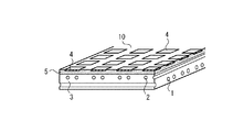
以下、本発明を実施するための最良の形態を図示例と共に説明する。図1は、本発明の物体検出装置の全体的な構成を説明するための概略図である。図示の通り、本発明の物体検出装置は、その検出面10には複数の第1ループ配線1からなる第1ループ配線群と複数の第2ループ配線2からなる第2ループ配線群とが設けられている。また、本発明の物体検出装置は、第1ループ配線1に接続され第1ループ配線群を駆動する駆動部20と、第2ループ配線1に接続され第2ループ配線群から電磁結合の変化を検出する検出部30とを具備する。なお、図示例では駆動部20が第1ループ配線1に接続され、検出部30が第2ループ配線2に接続された例を示しているが、本発明はこれに限定されず、駆動部20に第2ループ配線2を、検出部30に第1ループ配線1を接続しても勿論構わない。
The best mode for carrying out the present invention will be described below with reference to the drawings. FIG. 1 is a schematic diagram for explaining the overall configuration of the object detection apparatus of the present invention. As shown in the figure, the object detection device of the present invention is provided with a first loop wiring group consisting of a plurality of first loop wirings 1 and a second loop wiring group consisting of a plurality of
本発明の物体検出装置では、第1ループ配線1と第2ループ配線2により電磁結合部を提供する検出面10を構成し、第1ループ配線1を高周波駆動する。導電体からなる被測定物体が検出面に載せられると、被測定物体の影響(シールド効果)で電磁結合の度合いが弱くなり、第2ループ配線2から測定される誘導電流又は誘導電圧が小さくなる。一方、磁性体からなる被測定物が検出面に載せられると、電磁結合の度合いが強くなり、第2ループ配線2から測定される誘導電流又は誘導電圧が大きくなる。本発明の物体検出装置では、この現象を利用して電磁結合部に変化が現れた位置を検出し、被測定物体の形状や被測定物体からの距離を検出するものである。なお、導電率が一定ではない導電体や透磁率が一定でない磁性体の場合には、これらの変化分布を検出することも可能である。
In the object detection device of the present invention, the first loop wiring 1 and the
本発明の物体検出装置において、第1ループ配線群は、複数の第1ループ配線1が同一平面上に平行に配置されたものである。また、第2ループ配線群も複数の第2ループ配線2が同一平面上に平行に配置されたものである。そして、第2ループ配線群は第1ループ配線群と平行に配置され、さらに第2ループ配線2は、第1ループ配線1と直交するように設けられている。さらに、第1ループ配線群と第2ループ配線群は、それらの間の距離が一定に保たれるように所定のスペースを設けて配置される。すなわち、第1ループ配線群と第2ループ配線群の間には絶縁体3が配置され、第1ループ配線群と第2ループ配線群が接触せず且つそれらの間の距離が一定となるように構成されている。なお、絶縁体3は、検出面10を構成する部材と一体であっても別体であっても勿論構わない。
In the object detection device of the present invention, the first loop wiring group includes a plurality of first loop wirings 1 arranged in parallel on the same plane. The second loop wiring group also includes a plurality of
ここで、本発明の物体検出装置では、第1ループ配線1と第2ループ配線2とが電磁結合するように構成されている。以下、本発明の物体検出装置の電磁結合部のより具体的な構成について説明する。
Here, in the object detection apparatus of the present invention, the first loop wiring 1 and the
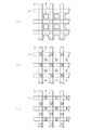
図2は、本発明の物体検出装置の電磁結合部の構成を説明するための検出面の一部の上面図であり、図2(a)が各配線をコイル状に形成したもの、図2(b)が一方の配線をコイル状に、他方を直線状に形成したもの、図2(c)が一方の配線を矩形状に、他方を直線状に形成したものを示している。本発明の物体検出装置において電磁結合部は、第1ループ配線1と第2ループ配線2とが電磁結合するように、図2(a)に示すように構成することができる。図2(a)の例では、第1ループ配線1が小さめのコイルを形成するようにアーチ状に形成され、その上に重なるように、これに直交する第2ループ配線2が大きめのコイルを形成するようにアーチ状に形成されている。このように構成することで、電磁結合部が提供可能である。なお、図示例では第1ループ配線で形成したコイル状のアーチの方が第2ループ配線で形成したコイル状のアーチよりも小さく形成されている例を示したが、本発明はこれに限定されず、同じ大きさで形成されても勿論構わない。
FIG. 2 is a top view of a part of the detection surface for explaining the configuration of the electromagnetic coupling portion of the object detection device of the present invention. FIG. 2 (a) is a diagram in which each wiring is formed in a coil shape. FIG. 2B shows one wiring formed in a coil shape and the other formed in a linear shape, and FIG. 2C shows one wiring formed in a rectangular shape and the other formed in a linear shape. In the object detection device of the present invention, the electromagnetic coupling unit can be configured as shown in FIG. 2A so that the first loop wiring 1 and the
また、電磁結合部の他の例としては、第1ループ配線と第2ループ配線とが電磁結合するように、電磁結合部を図2(b)に示すように構成することができる。図2(b)の例では、第2ループ配線2がコイルを形成するようにアーチ状に形成され、これに直交する第1ループ配線1が直線状に形成されている。このように構成しても、電磁結合部が提供可能である。なお、図示例では第2ループ配線2がアーチ状に形成され、第1ループ配線1が直線状に形成された例を示したが、本発明はこれに限定されず、逆に、第2ループ配線2が直線状に形成され、第1ループ配線1がアーチ状に形成されても構わない。なお、本発明の物体検出装置のループ配線は、アーチ状に限定されず、電磁結合するコイルを形成するものであれば、菱形状や螺旋形状等、種々の形状とすることが可能である。
As another example of the electromagnetic coupling unit, the electromagnetic coupling unit can be configured as shown in FIG. 2B so that the first loop wiring and the second loop wiring are electromagnetically coupled. In the example of FIG. 2B, the
さらに、電磁結合部の他の例としては、第1ループ配線と第2ループ配線とが電磁結合するように、電磁結合部を図2(c)に示すように構成することができる。図2(c)の例では、第2ループ配線2がコイルを形成するように矩形状に形成され、これに直交する第1ループ配線1が直線状に形成されている。このように構成しても、電磁結合部が提供可能である。なお、図示例では第2ループ配線2が矩形状に形成され、第1ループ配線1が直線状に形成された例を示したが、本発明はこれに限定されず、逆に、第2ループ配線2が直線状に形成され、第1ループ配線1が矩形状に形成されても構わない。さらに、第1ループ配線及び第2ループ配線の両方が矩形状に形成されても勿論構わない。
Furthermore, as another example of the electromagnetic coupling unit, the electromagnetic coupling unit can be configured as shown in FIG. 2C so that the first loop wiring and the second loop wiring are electromagnetically coupled. In the example of FIG. 2C, the
このように、第1ループ配線及び第2ループ配線は、互いに電磁結合するように構成されている。電磁結合部の形状としては、アーチ状や直線状、菱形状等、種々の形状のコイルとすることで電磁結合部を形成可能である。また、コイルの大きさに関しては、駆動側のループ配線と検出側のループ配線の電磁結合部のコイルの大きさが同じでも良いが、第1ループ配線と第2ループ配線とでコイルの大きさが異なるように形成されても良い。コイルの大きさを第1ループ配線と第2ループ配線とで変えると、検出感度が向上することが本願発明者による実験により明らかになった。所定の条件下で実験を行ったところ、被測定物体が検出面に置かれたときに、同じ大きさのコイルで駆動して検出した場合には、20%程度の変化が得られたが、どちらかのコイルの大きさを1/2にした場合には、60%程度の変化が得られた。この結果から明らかなように、検出感度を高くしたい場合には、コイルの大きさを変えることが好ましい。なお、大小どちらのコイルで駆動しても、同様の結果が得られた。 Thus, the first loop wiring and the second loop wiring are configured to be electromagnetically coupled to each other. As the shape of the electromagnetic coupling portion, the electromagnetic coupling portion can be formed by using coils having various shapes such as an arch shape, a linear shape, and a rhombus shape. Further, regarding the size of the coil, the coil size of the electromagnetic coupling portion of the driving side loop wiring and the detection side loop wiring may be the same, but the first loop wiring and the second loop wiring have the same coil size. May be formed differently. Experiments by the inventor of the present application revealed that detection sensitivity is improved when the size of the coil is changed between the first loop wiring and the second loop wiring. When an experiment was performed under a predetermined condition, when the object to be measured was placed on the detection surface and detected by driving with a coil of the same size, a change of about 20% was obtained. When either coil size was halved, a change of about 60% was obtained. As is clear from this result, it is preferable to change the size of the coil in order to increase the detection sensitivity. Similar results were obtained regardless of whether the coil was driven with a large or small coil.
また、本発明の物体検出装置においては、第1ループ配線と第2ループ配線とが間接的に電磁結合するように、電磁結合部を図3に示すように構成することができる。図3に、本発明の物体検出装置において、第1ループ配線と第2ループ配線とがそれぞれ直線状に形成され、これらが電磁結合するようにその近傍に導電性板を設けた例を示す。図3(a)はその検出面の一部上面図であり、図3(b)がその一部断面斜視図である。図示の通り、電磁結合部は、それぞれ直線状に形成された第1ループ配線1と第2ループ配線2の直交するそれぞれの位置の近傍に、導電性板4が形成されて提供されるものである。直線状に直交する第1ループ配線1と第2ループ配線2ではその間は電磁結合しないが、近傍に導電性板4を設けることで、導電性板4に生じる渦電流により間接的に電磁結合することになる。なお、図示例では、導電性板4を第1ループ配線1と第2ループ配線2とが直交する部分の上部に設けているが、本発明はこれに限定されず、電磁結合が生ずるように構成されれば、導電性板は直交する部分の下部に設けられても勿論良い。また、導電性板4は、第1ループ配線1と第2ループ配線2とが直交する部分を覆うように設けられているが、本発明はこれに限定されず、上部から見て配線上にかからないように、直交する配線で提供される四辺形状の内側に設けられても勿論構わない。なお、この場合には、第1ループ配線や第2ループ配線の上部ではなく、第1ループ配線又は第2ループ配線と同じ面内に設けられても良い。
In the object detection device of the present invention, the electromagnetic coupling unit can be configured as shown in FIG. 3 so that the first loop wiring and the second loop wiring are indirectly electromagnetically coupled. FIG. 3 shows an example in which, in the object detection device of the present invention, the first loop wiring and the second loop wiring are each formed in a straight line, and a conductive plate is provided in the vicinity thereof so that they are electromagnetically coupled. 3A is a partial top view of the detection surface, and FIG. 3B is a partial cross-sectional perspective view thereof. As shown in the figure, the electromagnetic coupling portion is provided by forming a
さらに、導電性板4の配置は、第1ループ配線1と第2ループ配線2とが直交する位置の近傍に設けられる以外に、以下で説明するようなパターンで設けても良い。図4は、本発明の物体検出装置における導電性板の配置例のバリエーションを説明するための図である。図4(a)は、第1ループ配線群の隣り合う第1ループ配線1間の近傍で、且つ第2ループ配線群の隣り合う第2ループ配線2間の近傍に、それぞれ導電性板4を形成した例を示している。図4(b)は、図3と図4(a)を組み合わせた配置例であり、第1ループ配線1と第2ループ配線2が直交する位置の近傍、及び第1ループ配線群の隣り合う第1ループ配線1間の近傍で且つ第2ループ配線群の隣り合う第2ループ配線2間の近傍に、それぞれ導電性板4を形成した例を示している。さらに、図4(c)は、第1ループ配線1の近傍で且つ隣り合う第2ループ配線2間の近傍、及び第2ループ配線2の近傍で且つ隣り合う第1ループ配線1間の近傍に、それぞれ導電性板4を形成した例を示している。このような種々のパターンで導電性板を設けることでも電磁結合部を構成することが可能である。なお、図示例の導電性板4は、上部から見て配線上にかからないように、直交する配線で提供される四辺形状の内側に設けられているが、本発明はこれに限定されず、図3に示すように、配線上にかかるように導電性板4を設けても構わない。
Furthermore, the
導電性板4は、検出面上に載せられる導電体又は磁性体からなる被測定物の形状や被測定物体からの距離を検出するためだけであれば、図3(b)に示したように、第1ループ配線群及び第2ループ配線群との距離が一定になるように固定されれば良い。なお、導電性板4は、検出面10を構成する絶縁体3に埋め込まれても良いし、別途保護シート等により導電性板4が外部に露出するのを保護しても構わない。さらに、導電性板4は、図示例では四辺形状のものを示したが、本発明はこれに限定されず、円形状のものであっても良く、さらに中心に孔が開いたコイル形状のものであっても構わない。
As shown in FIG. 3B, the
次に、本発明の物体検出装置における具体的な検出手順について図1を再度参照して説明する。まず、第1ループ配線群を駆動部20により駆動する。具体的には、駆動部20は高周波発振器21とドライバ22と切替器23とから主になるものであり、駆動部20を各第1ループ配線に順に接続していき、第1ループ配線1を順次駆動する。なお、第1ループ配線毎に駆動する周波数を変化させてすべての第1ループ配線を一度に駆動するように構成しても勿論構わない。
Next, a specific detection procedure in the object detection apparatus of the present invention will be described with reference to FIG. 1 again. First, the first loop wiring group is driven by the driving
一方、第2ループ配線2は、第1ループ配線1と第2ループ配線2との電磁結合の度合いの変化を検出する検出部30に接続される。検出部30は、切替器31とアンプ32と同期検波部33とA/D変換部34とから主になるものであり、検出部30を各第2ループ配線2に順に接続していき、第2ループ配線から誘導電流又は誘導電圧を順次検出する。同期検波部33には、発振器21からの出力も接続され、発振器21からの出力と第2ループ配線からの出力の積を取り、これを時間積分する。なお、第2ループ配線毎に別々に検出回路を設けたり周波数フィルタ回路等を組み合わせたりすることで、すべての検出コイルから一度に検出するように構成しても良い。
On the other hand, the
これらの駆動部20及び検出部30は、DSP等からなるマイクロコンピュータ40で制御され、所望な出力が得られるよう構成されている。具体的には、まず1つ目の第1ループ配線に駆動部20を接続し、検出部30を第2ループ配線に順次接続してそのときの出力信号を測定する。そして2つ目の第1ループ配線に駆動部20を接続し、検出部30を第2ループ配線に順次接続してそのときの出力信号を測定する。これを繰り返すことで、検出面10における第1ループ配線と第2ループ配線の交点をXY座標とするすべての位置における出力信号を測定することができる。なお、検出部30を1つ目の第2ループ配線に接続し、駆動部20を第1ループ配線に順次接続してそのときの出力信号を測定するようにしても勿論構わない。なお、駆動部及び検出部の構成は、上述の図示例に限定されるものではなく、第1ループ配線を駆動でき、第2ループ配線から誘導電流又は誘導電圧を検出できるものであれば如何なる構成であっても構わない。
The
さて、導電体が検出面10上に載せられると、導電体に覆われる第1ループ配線1と第2ループ配線2の交点部分の電磁結合が弱くなり、第2ループ配線2から測定される誘導電流又は誘導電圧が小さくなる。そこで、出力が小さくなったXY座標をプロットすることで、検出面上に載せられた導電体の形状を検出することが可能となる。また、導電体の検出面に載せられる側の面が平面ではなく曲面等の場合には、第2ループ配線2から測定される誘導電流又は誘導電圧が小さくなる度合いが変化する。そこで、この出力の大きさから、導電体と検出面との間の距離を検出することが可能となり、出力の変化分布から導電体の表面の状態を検出することが可能となる。なお、導電率が一定でない導電体を検出面上に載せた場合には、出力の変化分布から導電率の変化分布を検出することが可能となる。
When the conductor is placed on the
一方、磁性体が検出面10上に載せられると、磁性体に覆われる第1ループ配線1と第2ループ配線2の交点部分の電磁結合が強くなり、第2ループ配線2から測定される誘導電流又は誘導電圧が大きくなる。そこで、出力が大きくなったXY座標をプロットすることで、検出面上に載せられた磁性体の形状を検出することが可能となる。また、磁性体の検出面に載せられる側の面が平面ではなく曲面等の場合には、第2ループ配線2から測定される誘導電流又は誘導電圧が大きくなる度合いが変化する。そこで、この出力の大きさから、磁性体と検出面との間の距離を検出することが可能となり、出力の変化分布から磁性体の表面の状態を検出することが可能となる。なお、透磁率が一定でない磁性体を検出面上に載せた場合には、出力の変化分布から透磁率の変化分布を検出することが可能となる。
On the other hand, when the magnetic body is placed on the
次に、本発明の他の実施例について、図5を参照して説明する。図3に示した導電性板は、第1ループ配線群及び第2ループ配線群との距離が一定になるように固定されたものであったが、図5に示した実施例では、第1ループ配線群及び第2ループ配線群と導電性板との距離が変化するように構成されたものである。図示のように、絶縁体3内に第1ループ配線1と第2ループ配線2が設けられ、絶縁体3と導電性板4との間に、弾性体5が設けられている。導電性板4に圧力が加えられると、第1ループ配線群及び第2ループ配線群と導電性板4との距離が変化する。第1ループ配線群及び第2ループ配線群と導電性板4との距離が変化すると、第2ループ配線の出力信号も変化する。具体的には、第1ループ配線群及び第2ループ配線群と導電性板4との距離が狭くなると、電磁結合の度合いが強くなるため、第2ループ配線から測定される誘導電流又は誘導電圧が大きくなる。図5に示した本発明の物体検出装置ではこの現象を利用して、導電体や磁性体の形状や距離の検出だけでなく、電磁結合部に変化が現れた位置を圧力が加えられた指示位置として検出可能としたものである。
Next, another embodiment of the present invention will be described with reference to FIG. The conductive plate shown in FIG. 3 is fixed so that the distance between the first loop wiring group and the second loop wiring group is constant. In the embodiment shown in FIG. The distance between the loop wiring group and the second loop wiring group and the conductive plate is changed. As illustrated, the first loop wiring 1 and the
本実施例の物体検出装置における具体的な検出手順について説明すると、例えば検出面10上に、位置指示具として非導電体・非磁性体である指や絶縁体が載せられた場合、導電性板4が第1ループ配線1及び第2ループ配線2に近寄るため、その指示位置の電磁結合部の結合の度合いは強くなり、第2ループ配線2からの出力信号が大きくなる。一方、導電体が検出面10上に載せられた場合には、その重さにより導電性板4が第1ループ配線1及び第2ループ配線2に近寄り電磁結合の度合いが強くなるが、それ以上に導電体によるシールド効果が効いて、第2ループ配線2からの出力信号は減衰することになる。したがって、検出部30においては、第2ループ配線2からの出力信号が減衰したときには、検出面10上に載せられたものは導電体と判断して導電体の形状や導電体からの距離を検出する。また、検出部30は、第2ループ配線2からの出力信号が増加したときには、検出面10上に載せられたものは位置指示具と判断して位置指示具の指示位置を検出する。さらに、磁性体が載せられた場合には、出力信号は増加するが、圧力による出力信号の増加と比べると、より増加が大きいものであったり、指と比べて増加する領域が広いものであったりするため、位置指示具と磁性体との区別も可能である。
A specific detection procedure in the object detection apparatus of the present embodiment will be described. For example, when a finger or an insulator that is a non-conductor / non-magnetic member is placed on the
さらに、本発明の物体検出装置において、指以外の位置指示具としては、特定の周波数に同調する同調回路を有する位置指示具を適用することが可能である。この場合、駆動部20は、同調回路と同調する特定の周波数で第1ループ配線を駆動する。検出面10上に同調回路を有する位置指示具が載せられると、その指示位置の電磁結合部の結合の度合いは強くなり、第2ループ配線2からの出力信号が大きくなる。したがって、検出部30においては、第2ループ配線からの出力信号が減衰したときには、検出面10上に載せられたものは導電体と判断して導電体の形状や導電体からの距離を検出し、増加したときには、検出面10上に載せられたものは位置指示具と判断して位置指示具の指示位置を検出することが可能となる。なお、同調回路を有するものであれば、カード型やパッド型等、種々の形状のものであっても検出することが可能である。
Furthermore, in the object detection apparatus of the present invention, a position pointing tool having a tuning circuit that tunes to a specific frequency can be applied as a position pointing tool other than a finger. In this case, the
さらに、同調周波数とそれ以外の周波数で順次第1ループ配線1を駆動することにより、導電体又は磁性体の形状や距離の検出だけでなく、同調回路を有する位置指示具と同調回路を有さない位置指示具を区別して検出することも可能となる。以下、図6を用いて、同調回路を有する被測定物体と、同調回路を有さない被測定物体と、導電体又は磁性体とを区別してそれぞれ検出する手法について説明する。図6は、種々の被測定物体を測定するための手順を説明するためのフローチャートである。前提として、本発明の物体検出装置は、第1周波数fAと第2周波数fBで第1ループ配線群をそれぞれ駆動できるように構成されるものである。また、同調回路を有する位置指示具は、第2周波数fBに同調するものとする。Further, by sequentially driving the first loop wiring 1 at the tuning frequency and other frequencies, not only the shape or distance of the conductor or the magnetic material is detected, but also a position pointing device having a tuning circuit and a tuning circuit are provided. It is also possible to distinguish and detect non-position indicating tools. Hereinafter, a method of distinguishing and detecting a measured object having a tuning circuit, a measured object not having a tuning circuit, and a conductor or a magnetic material will be described with reference to FIG. FIG. 6 is a flowchart for explaining a procedure for measuring various objects to be measured. As a premise, the object detection device of the present invention is configured to be able to drive the first loop wiring group at the first frequency f A and the second frequency f B , respectively. The position pointing device having the tuning circuit shall be tuned to the second frequency f B.
まず、第1周波数fAで第1ループ配線1を駆動し、このときの出力信号Aijを第2ループ配線2から得る(ステップ100)。なお、i,jは各信号が得られるXY座標を表す。次に、この出力信号Aijが、検出面上に何も載せられていない状態の基準出力信号と比べて増加したか減衰したかを検出する(ステップ101)。出力信号Aijが減衰した場合には、導電体が検出面に載せられ、シールド効果により出力信号が減衰したものとして、導電体の形状や距離を検出する(ステップ102)。ステップ101で、出力信号Aijが増加した場合には、第2周波数fBで第1ループ配線1を駆動し、このときの出力信号Bijを得る(ステップ103)。次に、この出力信号Bijが出力信号Aijより大きいか否かを検出する(ステップ104)。出力信号Bijが出力信号Aijより大きくない場合(等しい場合)には、指等の非導電体・非磁性体からなる位置指示具が検出面に載せられ、圧力により導電性板4が第1ループ配線及び第2ループ配線に近づき出力信号が増加したものとして、指等の非導電体の物体の指示位置を検出する(ステップ105)。ステップ104で、出力信号Bijが出力信号Aijより大きい場合には、同調回路を有する位置指示具が検出面上に載せられ、これにより出力信号が増加したものとして、同調回路を有する位置指示具の指示位置を検出する(ステップ106)。これらのステップをすべてのループ配線について繰り返すことで、各種物体を区別してそれぞれ検出することが可能となる。First, the first loop wiring 1 is driven at the first frequency f A and the output signal A ij at this time is obtained from the second loop wiring 2 (step 100). Note that i and j represent XY coordinates from which each signal is obtained. Next, it is detected whether the output signal A ij has increased or attenuated compared to the reference output signal in a state where nothing is placed on the detection surface (step 101). When the output signal A ij is attenuated, the conductor is placed on the detection surface, and the shape and distance of the conductor are detected assuming that the output signal is attenuated by the shielding effect (step 102). If the output signal A ij increases in
なお、予め第1周波数fAと第2周波数fBで第1ループ配線群をそれぞれ駆動した上で、これらによる出力結果を蓄積し、出力信号Bijが出力信号Aijより大きいときには同調回路を有する位置指示具を検出し、出力信号Aijが増加したときには指等の非導電体の物体の指示位置を検出し、出力信号Aijが減衰したときには導電体の形状や距離を検出するようにしても勿論構わない。In addition, after driving the first loop wiring group in advance at the first frequency f A and the second frequency f B , the output results of these are accumulated, and when the output signal B ij is larger than the output signal A ij , the tuning circuit is turned on. When the output signal A ij increases, the pointing position of a non-conductor object such as a finger is detected, and when the output signal A ij attenuates, the shape and distance of the conductor are detected. But of course.
また、さらに別の同調回路を有する位置指示具を用いて、その別の同調回路に同調する周波数で第1ループ配線を駆動させることで、さらに多くの位置指示具を区別して検出することが可能となる。なお、周波数を可変させた場合、周波数が高くなるほど渦電流が増加するため、検出面上に載せられた物体に変化がなくても厳密には出力信号に変化が現れてしまう。したがって、これを考慮した補正回路を設けたり、所定の閾値以下の変化は測定しないようにすること等により、周波数の変化による出力信号の変化を補償することも可能である。 Further, by using a position indicator having another tuning circuit and driving the first loop wiring at a frequency tuned to the other tuning circuit, it is possible to distinguish and detect more position indicators. It becomes. Note that, when the frequency is varied, the eddy current increases as the frequency increases, so that the output signal changes strictly even if the object placed on the detection surface does not change. Therefore, it is possible to compensate for a change in the output signal due to a change in frequency by providing a correction circuit taking this into account, or by not measuring a change below a predetermined threshold.
なお、本発明の物体検出装置は、上述の図示例にのみ限定されるものではなく、本発明の要旨を逸脱しない範囲内において種々変更を加え得ることは勿論である。 It should be noted that the object detection device of the present invention is not limited to the illustrated examples described above, and it is needless to say that various modifications can be made without departing from the scope of the present invention.
1 第1ループ配線
2 第2ループ配線
3 絶縁体
4 導電性板
5 弾性体
10 検出面
20 駆動部
21 発振器
22 ドライバ
23 切替器
30 検出部
31 切替器
32 アンプ
33 同期検波部
34 A/D変換部
40 マイクロコンピュータDESCRIPTION OF SYMBOLS 1
Claims (12)
複数のコイル状部分をそれぞれ有する複数の第1ループ配線が同一平面上に平行に配置される第1ループ配線群と、
複数のコイル状部分をそれぞれ有する複数の第2ループ配線が同一平面上に平行に配置される第2ループ配線群であって、該第2ループ配線群は第1ループ配線群と平行であり、前記複数の第2ループ配線は複数の第1ループ配線とそれぞれ直交する方向に配置される、第2ループ配線群と、
前記第1ループ配線群と第2ループ配線群との間の距離を一定に保つスペーサ手段と、
前記第1ループ配線と第2ループ配線が直交するそれぞれの位置に前記コイル状部分が配置されることで前記第1ループ配線と第2ループ配線が電磁結合するように構成される複数の電磁結合部と、
前記第1ループ配線群又は第2ループ配線群の一方に接続され、該ループ配線群を駆動する駆動手段と、
前記第1ループ配線群又は第2ループ配線群の他方に接続され、該ループ配線群から前記電磁結合部の電磁結合の変化を検出する検出手段であって、前記検出面上に被測定物体及びこれと異なる位置指示手段が載せられる場合に、前記検出手段は、第1ループ配線群及び第2ループ配線群の一方からの出力信号が減衰したときには被測定物体の形状を検出し、増加したときには位置指示手段の指示位置を検出する、検出手段と、
を具備することを特徴とする物体検出装置。An object detection device for detecting a shape of a measured object made of a conductor or a magnetic material placed on a detection surface using electromagnetic induction and a distance from the measured object, the device comprising:
A first loop wiring group in which a plurality of first loop wirings each having a plurality of coiled portions are arranged in parallel on the same plane;
A second loop wiring group in which a plurality of second loop wirings each having a plurality of coil-shaped portions are arranged in parallel on the same plane, the second loop wiring group being parallel to the first loop wiring group; A plurality of second loop wirings arranged in directions orthogonal to the plurality of first loop wirings;
Spacer means for maintaining a constant distance between the first loop wiring group and the second loop wiring group;
A plurality of electromagnetic couplings configured such that the first loop wiring and the second loop wiring are electromagnetically coupled by disposing the coiled portion at each position where the first loop wiring and the second loop wiring are orthogonal to each other. And
Driving means connected to one of the first loop wiring group or the second loop wiring group and driving the loop wiring group;
Detection means connected to the other of the first loop wiring group or the second loop wiring group and detecting a change in electromagnetic coupling of the electromagnetic coupling unit from the loop wiring group , the object to be measured on the detection surface, and When a different position indicating means is mounted, the detecting means detects the shape of the object to be measured when the output signal from one of the first loop wiring group and the second loop wiring group is attenuated, and when the output signal is increased, Detecting means for detecting the indicated position of the position indicating means ;
An object detection apparatus comprising:
複数のコイル状部分をそれぞれ有する複数の第1ループ配線が同一平面上に平行に配置される第1ループ配線群と、
複数のコイル状部分をそれぞれ有する複数の第2ループ配線が同一平面上に平行に配置される第2ループ配線群であって、該第2ループ配線群は第1ループ配線群と平行であり、前記複数の第2ループ配線は複数の第1ループ配線とそれぞれ直交する方向に配置され、前記第1ループ配線のコイル状部分の大きさと第2ループ配線のコイル状部分の大きさが、それぞれ異なる、第2ループ配線群と、
前記第1ループ配線群と第2ループ配線群との間の距離を一定に保つスペーサ手段と、
前記第1ループ配線と第2ループ配線が直交するそれぞれの位置に前記コイル状部分が配置されることで前記第1ループ配線と第2ループ配線が電磁結合するように構成される複数の電磁結合部と、
前記第1ループ配線群又は第2ループ配線群の一方に接続され、該ループ配線群を駆動する駆動手段と、
前記第1ループ配線群又は第2ループ配線群の他方に接続され、該ループ配線群から前記電磁結合部の電磁結合の変化を検出する検出手段と、
を具備することを特徴とする物体検出装置。 An object detection device for detecting a shape of a measured object made of a conductor or a magnetic material placed on a detection surface using electromagnetic induction and a distance from the measured object, the device comprising:
A first loop wiring group in which a plurality of first loop wirings each having a plurality of coiled portions are arranged in parallel on the same plane;
A second loop wiring group in which a plurality of second loop wirings each having a plurality of coil-shaped portions are arranged in parallel on the same plane, the second loop wiring group being parallel to the first loop wiring group; The plurality of second loop wirings are arranged in directions orthogonal to the plurality of first loop wirings, and the size of the coiled portion of the first loop wiring is different from the size of the coiled portion of the second loop wiring. A second loop wiring group;
Spacer means for maintaining a constant distance between the first loop wiring group and the second loop wiring group;
A plurality of electromagnetic couplings configured such that the first loop wiring and the second loop wiring are electromagnetically coupled by disposing the coiled portion at each position where the first loop wiring and the second loop wiring are orthogonal to each other. And
Driving means connected to one of the first loop wiring group or the second loop wiring group and driving the loop wiring group;
Detecting means connected to the other of the first loop wiring group or the second loop wiring group and detecting a change in electromagnetic coupling of the electromagnetic coupling unit from the loop wiring group;
An object detection apparatus comprising:
複数のコイル状部分をそれぞれ有する複数の第1ループ配線が同一平面上に平行に配置される第1ループ配線群と、
複数の直線状の第2ループ配線が同一平面上に平行に配置される第2ループ配線群であって、該第2ループ配線群は第1ループ配線群と平行であり、前記複数の第2ループ配線は複数の第1ループ配線とそれぞれ直交する方向に配置される、第2ループ配線群と、
前記第1ループ配線群と第2ループ配線群との間の距離を一定に保つスペーサ手段と、
前記第1ループ配線と第2ループ配線が直交するそれぞれの位置に前記コイル状部分が配置されることで前記第1ループ配線と第2ループ配線が電磁結合するように構成される複数の電磁結合部と、
前記第1ループ配線群又は第2ループ配線群の一方に接続され、該ループ配線群を駆動する駆動手段と、
前記第1ループ配線群又は第2ループ配線群の他方に接続され、該ループ配線群から前記電磁結合部の電磁結合の変化を検出する検出手段であって、前記検出面上に被測定物体及びこれと異なる位置指示手段が載せられる場合に、前記検出手段は、第1ループ配線群及び第2ループ配線群の一方からの出力信号が減衰したときには被測定物体の形状を検出し、増加したときには位置指示手段の指示位置を検出する、検出手段と、
を具備することを特徴とする物体検出装置。An object detection device for detecting a shape of a measured object made of a conductor or a magnetic material placed on a detection surface using electromagnetic induction and a distance from the measured object, the device comprising:
A first loop wiring group in which a plurality of first loop wirings each having a plurality of coiled portions are arranged in parallel on the same plane;
A second loop wiring group in which a plurality of linear second loop wirings are arranged in parallel on the same plane, and the second loop wiring group is parallel to the first loop wiring group, and the plurality of second loop wirings The loop wiring is arranged in a direction orthogonal to each of the plurality of first loop wirings, a second loop wiring group,
Spacer means for maintaining a constant distance between the first loop wiring group and the second loop wiring group;
A plurality of electromagnetic couplings configured such that the first loop wiring and the second loop wiring are electromagnetically coupled by disposing the coiled portion at each position where the first loop wiring and the second loop wiring are orthogonal to each other. And
Driving means connected to one of the first loop wiring group or the second loop wiring group and driving the loop wiring group;
Detection means connected to the other of the first loop wiring group or the second loop wiring group and detecting a change in electromagnetic coupling of the electromagnetic coupling unit from the loop wiring group , the object to be measured on the detection surface, and When a different position indicating means is mounted, the detecting means detects the shape of the object to be measured when the output signal from one of the first loop wiring group and the second loop wiring group is attenuated, and when the output signal is increased, Detecting means for detecting the indicated position of the position indicating means ;
An object detection apparatus comprising:
複数の直線状の第1ループ配線が同一平面上に平行に配置される第1ループ配線群と、
複数の直線状の第2ループ配線が同一平面上に平行に配置される第2ループ配線群であって、該第2ループ配線群は第1ループ配線群と平行であり、前記複数の第2ループ配線は複数の第1ループ配線とそれぞれ直交する方向に配置される、第2ループ配線群と、
前記第1ループ配線群と第2ループ配線群との間の距離を一定に保つスペーサ手段と、
前記第1ループ配線と第2ループ配線が直交するそれぞれの位置の近傍に複数の導電性板がそれぞれ配置されることで前記第1ループ配線と第2ループ配線が電磁結合するように構成される複数の電磁結合部と、
前記第1ループ配線群又は第2ループ配線群の一方に接続され、該ループ配線群を駆動する駆動手段と、
前記第1ループ配線群又は第2ループ配線群の他方に接続され、該ループ配線群から前記電磁結合部の電磁結合の変化を検出する検出手段と、
を具備することを特徴とする物体検出装置。An object detection device for detecting a shape of a measured object made of a conductor or a magnetic material placed on a detection surface using electromagnetic induction and a distance from the measured object, the device comprising:
A first loop wiring group in which a plurality of linear first loop wirings are arranged in parallel on the same plane;
A second loop wiring group in which a plurality of linear second loop wirings are arranged in parallel on the same plane, and the second loop wiring group is parallel to the first loop wiring group, and the plurality of second loop wirings The loop wiring is arranged in a direction orthogonal to each of the plurality of first loop wirings, a second loop wiring group,
Spacer means for maintaining a constant distance between the first loop wiring group and the second loop wiring group;
The first loop wiring and the second loop wiring are configured to be electromagnetically coupled by disposing a plurality of conductive plates in the vicinity of positions where the first loop wiring and the second loop wiring are orthogonal to each other. A plurality of electromagnetic coupling parts;
Driving means connected to one of the first loop wiring group or the second loop wiring group and driving the loop wiring group;
Detecting means connected to the other of the first loop wiring group or the second loop wiring group and detecting a change in electromagnetic coupling of the electromagnetic coupling unit from the loop wiring group;
An object detection apparatus comprising:
前記駆動手段は、第1周波数及び第2周波数で前記第1ループ配線群及び第2ループ配線群の他方を駆動し、
前記同調回路は、第2周波数に同調し、
前記検出手段は、第1ループ配線群及び前記第2ループ配線群の一方からの出力信号が、前記第1ループ配線群及び第2ループ配線群の他方が第1周波数で駆動されるときに減衰したときには被測定物体の形状を検出し増加したときには前記同調回路を有さない位置指示手段の指示位置を検出し、前記第1ループ配線群及び第2ループ配線群の他方が第2周波数で駆動されるときの出力信号が第1周波数で駆動されるときの出力信号より大きいときには前記同調回路を有する位置指示手段の指示位置を検出することを特徴とする物体検出装置。In the object detection device according to claim 11, when the object to be measured, the position indicating means having a tuning circuit, and the position indicating means not having a tuning circuit are placed on the detection surface,
The driving means drives the other of the first loop wiring group and the second loop wiring group at a first frequency and a second frequency,
The tuning circuit is tuned to a second frequency;
The detection means attenuates an output signal from one of the first loop wiring group and the second loop wiring group when the other of the first loop wiring group and the second loop wiring group is driven at a first frequency. The shape of the object to be measured is detected when it increases, and when it increases, the pointing position of the position pointing means that does not have the tuning circuit is detected, and the other of the first loop wiring group and the second loop wiring group is driven at the second frequency. An object detection apparatus for detecting an indication position of a position indication means having the tuning circuit when an output signal at the time of being operated is larger than an output signal when driven at a first frequency.
Priority Applications (1)
| Application Number | Priority Date | Filing Date | Title |
|---|---|---|---|
| JP2008522287A JP5028552B2 (en) | 2006-06-19 | 2007-06-04 | Object detection device for detecting an object using electromagnetic induction |
Applications Claiming Priority (4)
| Application Number | Priority Date | Filing Date | Title |
|---|---|---|---|
| JP2006169145 | 2006-06-19 | ||
| JP2006169145 | 2006-06-19 | ||
| PCT/JP2007/000596 WO2007148429A1 (en) | 2006-06-19 | 2007-06-04 | Object detecting device for detecting an object by electromagnetic induction |
| JP2008522287A JP5028552B2 (en) | 2006-06-19 | 2007-06-04 | Object detection device for detecting an object using electromagnetic induction |
Publications (2)
| Publication Number | Publication Date |
|---|---|
| JPWO2007148429A1 JPWO2007148429A1 (en) | 2009-11-12 |
| JP5028552B2 true JP5028552B2 (en) | 2012-09-19 |
Family
ID=38833176
Family Applications (1)
| Application Number | Title | Priority Date | Filing Date |
|---|---|---|---|
| JP2008522287A Expired - Fee Related JP5028552B2 (en) | 2006-06-19 | 2007-06-04 | Object detection device for detecting an object using electromagnetic induction |
Country Status (6)
| Country | Link |
|---|---|
| US (1) | US8013598B2 (en) |
| EP (1) | EP2031346A4 (en) |
| JP (1) | JP5028552B2 (en) |
| KR (1) | KR101098200B1 (en) |
| CN (1) | CN101473188B (en) |
| WO (1) | WO2007148429A1 (en) |
Families Citing this family (15)
| Publication number | Priority date | Publication date | Assignee | Title |
|---|---|---|---|---|
| KR101128751B1 (en) | 2006-10-24 | 2012-04-12 | 뉴콤 테크노 가부시키가이샤 | Operating tool with conductor piece |
| JP2010169462A (en) * | 2009-01-21 | 2010-08-05 | Newcom Inc | Device for detecting input object information by detecting variation in degree of inductive coupling |
| US8339372B2 (en) * | 2009-04-20 | 2012-12-25 | Broadcom Corporation | Inductive touch screen with integrated antenna for use in a communication device and methods for use therewith |
| US8810523B2 (en) | 2009-04-20 | 2014-08-19 | Broadcom Corporation | Inductive touch screen and methods for use therewith |
| US20130127736A1 (en) * | 2011-11-18 | 2013-05-23 | Qualcomm Mems Technologies, Inc. | Electromagnetic touchscreen |
| KR20130107886A (en) * | 2012-03-23 | 2013-10-02 | 삼성전기주식회사 | Digitizer |
| KR102089607B1 (en) * | 2013-05-28 | 2020-03-17 | 삼성디스플레이 주식회사 | Display device |
| KR102111032B1 (en) * | 2013-08-14 | 2020-05-15 | 삼성디스플레이 주식회사 | Touch sensing display device |
| CN104990494B (en) * | 2015-03-05 | 2016-09-07 | 三峡大学 | A device and method for quickly measuring shaft hole parameters |
| JP6698386B2 (en) | 2016-03-10 | 2020-05-27 | 株式会社ジャパンディスプレイ | Display device and touch detection device |
| JP6677587B2 (en) * | 2016-06-24 | 2020-04-08 | 株式会社ワコム | Position detecting apparatus and position detecting sensor control method |
| US11442569B2 (en) * | 2018-02-15 | 2022-09-13 | Tactual Labs Co. | Apparatus and method for sensing pressure |
| CN109188534B (en) * | 2018-09-11 | 2020-02-04 | 电子科技大学 | Underwater metal shape detection method and device based on active electric field principle |
| JP7091963B2 (en) * | 2018-09-14 | 2022-06-28 | オムロン株式会社 | Object detection sensor and object detection system |
| CN110703959B (en) * | 2019-08-26 | 2021-01-29 | 华为技术有限公司 | Input device and method |
Citations (7)
| Publication number | Priority date | Publication date | Assignee | Title |
|---|---|---|---|---|
| JPS4922162A (en) * | 1972-06-16 | 1974-02-27 | ||
| JPS5057125A (en) * | 1973-09-18 | 1975-05-19 | ||
| JPS5245823A (en) * | 1975-10-09 | 1977-04-11 | Kazunari Imahashi | Chinese character input unit |
| JPH04152957A (en) * | 1990-04-19 | 1992-05-26 | Ace Denken:Kk | Metal sensor and pinball game machine |
| JPH05231809A (en) * | 1992-02-24 | 1993-09-07 | Nippon Denshi Kogyo Kk | Electromotive force type eddy current displacement gauge |
| JP2005156474A (en) * | 2003-11-28 | 2005-06-16 | Xiroku:Kk | Pressure sensor using electromagnetic coupling |
| JP3928976B1 (en) * | 2006-01-19 | 2007-06-13 | 株式会社シロク | Pressure distribution detector using electromagnetic coupling |
Family Cites Families (51)
| Publication number | Priority date | Publication date | Assignee | Title |
|---|---|---|---|---|
| US3021711A (en) * | 1957-05-10 | 1962-02-20 | Svenska Flygmotor Aktiebolaget | Device for measuring pressure or difference of pressure in fluids |
| US3722288A (en) * | 1969-01-31 | 1973-03-27 | Hughes Aircraft Co | Electromagnetic coupled detector of dynamic gravitational force gradients |
| JPS5146714U (en) | 1974-10-01 | 1976-04-07 | ||
| JPS5146714A (en) | 1974-10-18 | 1976-04-21 | Ig Gijutsu Kenkyusho Kk | Zooryutaikazai oyobi zooryutaikazaio mochiitenaru taikapaneru |
| JPS5245823U (en) | 1975-02-28 | 1977-03-31 | ||
| US4353050A (en) * | 1980-06-13 | 1982-10-05 | Ranco Incorporated | Displacement measuring transducer |
| JPS5711331A (en) | 1980-06-24 | 1982-01-21 | Takeo Uchida | Shouldering tool |
| JPS57100331A (en) | 1980-12-15 | 1982-06-22 | Agency Of Ind Science & Technol | Measuring device for load distribution |
| JPS57165849A (en) | 1981-04-07 | 1982-10-13 | Ricoh Co Ltd | Electrophotographic toner |
| JPS5971141U (en) | 1982-11-02 | 1984-05-15 | 株式会社東芝 | load cell |
| JPS60221820A (en) * | 1983-08-05 | 1985-11-06 | Wacom Co Ltd | Position detecting device |
| JPS61135240A (en) | 1984-12-05 | 1986-06-23 | Fujitsu Ltd | Signal selecting and receiving circuit |
| JPH0652206B2 (en) | 1986-03-28 | 1994-07-06 | 工業技術院長 | Capacitance type pressure distribution measuring device |
| JPH0610269Y2 (en) | 1986-10-27 | 1994-03-16 | 池田物産株式会社 | Pressure distribution measuring device |
| JPH0646171B2 (en) | 1987-09-19 | 1994-06-15 | 工業技術院長 | Pressure sensor |
| JPH01212301A (en) | 1988-02-19 | 1989-08-25 | Toshiba Corp | Strain sensor |
| US4918418A (en) * | 1988-08-04 | 1990-04-17 | Caterpillar Inc. | Inductive coil structure with electrical return path |
| JPH0278925A (en) | 1988-09-16 | 1990-03-19 | Yokohama Syst Kenkyusho:Kk | Electrostatic capacity type pressure sensor |
| US4944187A (en) * | 1988-12-23 | 1990-07-31 | Rosemount Inc. | Multimodulus pressure sensor |
| US5120908A (en) * | 1990-11-01 | 1992-06-09 | Gazelle Graphic Systems Inc. | Electromagnetic position transducer |
| WO1993022618A1 (en) * | 1992-04-28 | 1993-11-11 | Kabushiki Kaisha Ace Denken | Metal body detector for detecting position of metal body |
| US5861583A (en) | 1992-06-08 | 1999-01-19 | Synaptics, Incorporated | Object position detector |
| US5543588A (en) | 1992-06-08 | 1996-08-06 | Synaptics, Incorporated | Touch pad driven handheld computing device |
| JPH0755615A (en) | 1993-08-10 | 1995-03-03 | Agency Of Ind Science & Technol | Capacitance type force sensor |
| JPH09113203A (en) | 1995-10-16 | 1997-05-02 | Toyoda Mach Works Ltd | Differential transformer and measuring device using it |
| JPH10198494A (en) | 1997-01-01 | 1998-07-31 | Wacom Co Ltd | Data tablet |
| US6338199B1 (en) | 1997-03-25 | 2002-01-15 | Canon Kabushiki Kaisha | Sensor |
| EP0897161B1 (en) | 1997-08-07 | 2007-10-10 | Fujitsu Limited | Optical scanning-type touch panel |
| JP3543695B2 (en) | 1999-03-17 | 2004-07-14 | 富士ゼロックス株式会社 | Driving force generator |
| JP2000322201A (en) | 1999-05-06 | 2000-11-24 | Ricoh Co Ltd | Coordinate input device |
| JP3934846B2 (en) * | 2000-03-06 | 2007-06-20 | 株式会社リコー | Coordinate input / detection device, electronic blackboard system, light receiving element positional deviation correction method, and storage medium |
| JP2001265517A (en) | 2000-03-17 | 2001-09-28 | Ricoh Co Ltd | Coordinate input device, sensor head mounting method, display device with coordinate input device, and recording medium |
| US6690363B2 (en) * | 2000-06-19 | 2004-02-10 | Next Holdings Limited | Touch panel display system |
| US6803906B1 (en) * | 2000-07-05 | 2004-10-12 | Smart Technologies, Inc. | Passive touch system and method of detecting user input |
| EP1297488B1 (en) | 2000-07-05 | 2006-11-15 | Smart Technologies Inc. | Camera-based touch system |
| US6471613B1 (en) | 2000-08-23 | 2002-10-29 | Daimlerchrysler Corporation | Transmission with variable line pressure |
| JP3736440B2 (en) | 2001-02-02 | 2006-01-18 | 株式会社セガ | Card and card game device |
| JP2002268807A (en) | 2001-03-14 | 2002-09-20 | Ricoh Co Ltd | Coordinate input device, program for executing coordinate input function, and recording medium storing the program |
| JP4768143B2 (en) * | 2001-03-26 | 2011-09-07 | 株式会社リコー | Information input / output device, information input / output control method, and program |
| US6960911B2 (en) * | 2002-01-29 | 2005-11-01 | Kabushiki Kaisha Toshiba | Strain sensor |
| JP3645553B2 (en) | 2002-01-29 | 2005-05-11 | 株式会社東芝 | Strain sensor |
| JP2003337071A (en) | 2002-05-20 | 2003-11-28 | Yokohama Tlo Co Ltd | Tactile sensor |
| DE10252862B3 (en) * | 2002-11-12 | 2004-07-15 | Deutsches Zentrum für Luft- und Raumfahrt e.V. | Force measuring device using multi-layer sensor elements, e.g. for tactile skin for robot gripper, direct pressure measurement or orthopaedic diagnosis system |
| US7256772B2 (en) * | 2003-04-08 | 2007-08-14 | Smart Technologies, Inc. | Auto-aligning touch system and method |
| WO2004104810A1 (en) | 2003-05-19 | 2004-12-02 | Eit Co., Ltd. | Position sensor using area image sensor |
| GB0313808D0 (en) * | 2003-06-14 | 2003-07-23 | Binstead Ronald P | Improvements in touch technology |
| JP2005275760A (en) | 2004-03-24 | 2005-10-06 | Ntt Comware Corp | Pack device, sense table management device, movement locus calculation method, movement locus calculation program, and recording medium |
| US7703342B2 (en) | 2005-03-30 | 2010-04-27 | Xiroku, Inc. | Pressure distribution detection device |
| US7602157B2 (en) | 2005-12-28 | 2009-10-13 | Flyback Energy, Inc. | Supply architecture for inductive loads |
| WO2008007458A1 (en) | 2006-07-14 | 2008-01-17 | Newcom, Inc. | Pressure distribution sensor utilizing electromagnetic coupling |
| KR101128751B1 (en) | 2006-10-24 | 2012-04-12 | 뉴콤 테크노 가부시키가이샤 | Operating tool with conductor piece |
-
2007
- 2007-06-04 US US12/304,226 patent/US8013598B2/en not_active Expired - Fee Related
- 2007-06-04 CN CN2007800224636A patent/CN101473188B/en not_active Expired - Fee Related
- 2007-06-04 EP EP07737252.2A patent/EP2031346A4/en not_active Withdrawn
- 2007-06-04 KR KR1020087028588A patent/KR101098200B1/en not_active Expired - Fee Related
- 2007-06-04 JP JP2008522287A patent/JP5028552B2/en not_active Expired - Fee Related
- 2007-06-04 WO PCT/JP2007/000596 patent/WO2007148429A1/en not_active Ceased
Patent Citations (7)
| Publication number | Priority date | Publication date | Assignee | Title |
|---|---|---|---|---|
| JPS4922162A (en) * | 1972-06-16 | 1974-02-27 | ||
| JPS5057125A (en) * | 1973-09-18 | 1975-05-19 | ||
| JPS5245823A (en) * | 1975-10-09 | 1977-04-11 | Kazunari Imahashi | Chinese character input unit |
| JPH04152957A (en) * | 1990-04-19 | 1992-05-26 | Ace Denken:Kk | Metal sensor and pinball game machine |
| JPH05231809A (en) * | 1992-02-24 | 1993-09-07 | Nippon Denshi Kogyo Kk | Electromotive force type eddy current displacement gauge |
| JP2005156474A (en) * | 2003-11-28 | 2005-06-16 | Xiroku:Kk | Pressure sensor using electromagnetic coupling |
| JP3928976B1 (en) * | 2006-01-19 | 2007-06-13 | 株式会社シロク | Pressure distribution detector using electromagnetic coupling |
Also Published As
| Publication number | Publication date |
|---|---|
| EP2031346A1 (en) | 2009-03-04 |
| CN101473188B (en) | 2011-01-19 |
| KR20090020575A (en) | 2009-02-26 |
| JPWO2007148429A1 (en) | 2009-11-12 |
| KR101098200B1 (en) | 2011-12-23 |
| CN101473188A (en) | 2009-07-01 |
| US8013598B2 (en) | 2011-09-06 |
| US20090146654A1 (en) | 2009-06-11 |
| EP2031346A4 (en) | 2014-07-02 |
| WO2007148429A1 (en) | 2007-12-27 |
Similar Documents
| Publication | Publication Date | Title |
|---|---|---|
| JP5028552B2 (en) | Object detection device for detecting an object using electromagnetic induction | |
| KR101975596B1 (en) | Touch screen device for compensating distortion of input sensing signal | |
| US7916501B2 (en) | Magnetic shield for use in a location sensing system | |
| TWI429882B (en) | A position detecting device and a display device | |
| JP6186081B2 (en) | Tablet with electromagnetic induction type position sensing and capacitance type position sensing | |
| EP2333648B1 (en) | Position detecting device | |
| EP2077489B1 (en) | Position detecting device | |
| US8665211B2 (en) | Position detecting device and position input device | |
| US10495486B2 (en) | Inductive touch input | |
| CN102680567A (en) | Eddy current detector | |
| JP3928976B1 (en) | Pressure distribution detector using electromagnetic coupling | |
| JP5055172B2 (en) | Capacitive proximity sensor | |
| JP2015130064A (en) | Touch pad with antenna | |
| JP2010055385A (en) | Digitizer capable of discriminating among indicators | |
| KR20200097570A (en) | Touch sensor module | |
| JP2007157107A5 (en) | ||
| JP4747041B2 (en) | Tile unit constituting the detection surface of a detection device using electromagnetic induction | |
| JP2010085378A (en) | Position detector for detecting indicated position of indicating tool using electromagnetic induction | |
| EP4160923A1 (en) | Button arrangement and method of operation | |
| KR102293936B1 (en) | Touch sensor module | |
| EP3631526B1 (en) | Foreign object detector, foreign object detection system, use of a foreign object detector, and method of detecting a foreign object | |
| JP2008032589A (en) | Object detecting device using variation of inductance | |
| JPH10269009A (en) | Coordinate detector | |
| JPH0656825U (en) | Digitizer tablet | |
| HK1216410B (en) | A safety system, a method of operating a safety system and a method of building a safety system |
Legal Events
| Date | Code | Title | Description |
|---|---|---|---|
| A131 | Notification of reasons for refusal |
Free format text: JAPANESE INTERMEDIATE CODE: A131 Effective date: 20110201 |
|
| A521 | Request for written amendment filed |
Free format text: JAPANESE INTERMEDIATE CODE: A523 Effective date: 20110404 |
|
| A131 | Notification of reasons for refusal |
Free format text: JAPANESE INTERMEDIATE CODE: A131 Effective date: 20110816 |
|
| A521 | Request for written amendment filed |
Free format text: JAPANESE INTERMEDIATE CODE: A523 Effective date: 20111005 |
|
| TRDD | Decision of grant or rejection written | ||
| A01 | Written decision to grant a patent or to grant a registration (utility model) |
Free format text: JAPANESE INTERMEDIATE CODE: A01 Effective date: 20120301 |
|
| A711 | Notification of change in applicant |
Free format text: JAPANESE INTERMEDIATE CODE: A711 Effective date: 20120322 |
|
| A61 | First payment of annual fees (during grant procedure) |
Free format text: JAPANESE INTERMEDIATE CODE: A61 Effective date: 20120322 |
|
| R150 | Certificate of patent or registration of utility model |
Ref document number: 5028552 Country of ref document: JP Free format text: JAPANESE INTERMEDIATE CODE: R150 Free format text: JAPANESE INTERMEDIATE CODE: R150 |
|
| FPAY | Renewal fee payment (event date is renewal date of database) |
Free format text: PAYMENT UNTIL: 20150706 Year of fee payment: 3 |
|
| FPAY | Renewal fee payment (event date is renewal date of database) |
Free format text: PAYMENT UNTIL: 20150706 Year of fee payment: 3 |
|
| FPAY | Renewal fee payment (event date is renewal date of database) |
Free format text: PAYMENT UNTIL: 20150706 Year of fee payment: 3 |
|
| R250 | Receipt of annual fees |
Free format text: JAPANESE INTERMEDIATE CODE: R250 |
|
| R250 | Receipt of annual fees |
Free format text: JAPANESE INTERMEDIATE CODE: R250 |
|
| R250 | Receipt of annual fees |
Free format text: JAPANESE INTERMEDIATE CODE: R250 |
|
| R250 | Receipt of annual fees |
Free format text: JAPANESE INTERMEDIATE CODE: R250 |
|
| S111 | Request for change of ownership or part of ownership |
Free format text: JAPANESE INTERMEDIATE CODE: R313113 |
|
| R350 | Written notification of registration of transfer |
Free format text: JAPANESE INTERMEDIATE CODE: R350 |
|
| R250 | Receipt of annual fees |
Free format text: JAPANESE INTERMEDIATE CODE: R250 |
|
| R250 | Receipt of annual fees |
Free format text: JAPANESE INTERMEDIATE CODE: R250 |
|
| S531 | Written request for registration of change of domicile |
Free format text: JAPANESE INTERMEDIATE CODE: R313531 |
|
| S111 | Request for change of ownership or part of ownership |
Free format text: JAPANESE INTERMEDIATE CODE: R313113 |
|
| R350 | Written notification of registration of transfer |
Free format text: JAPANESE INTERMEDIATE CODE: R350 |
|
| R250 | Receipt of annual fees |
Free format text: JAPANESE INTERMEDIATE CODE: R250 |
|
| R250 | Receipt of annual fees |
Free format text: JAPANESE INTERMEDIATE CODE: R250 |
|
| R250 | Receipt of annual fees |
Free format text: JAPANESE INTERMEDIATE CODE: R250 |
|
| LAPS | Cancellation because of no payment of annual fees |