JP2010064171A - Machining tool with fluid supplying hole - Google Patents
Machining tool with fluid supplying hole Download PDFInfo
- Publication number
- JP2010064171A JP2010064171A JP2008231580A JP2008231580A JP2010064171A JP 2010064171 A JP2010064171 A JP 2010064171A JP 2008231580 A JP2008231580 A JP 2008231580A JP 2008231580 A JP2008231580 A JP 2008231580A JP 2010064171 A JP2010064171 A JP 2010064171A
- Authority
- JP
- Japan
- Prior art keywords
- fluid
- rear end
- fluid supply
- opening
- pair
- Prior art date
- Legal status (The legal status is an assumption and is not a legal conclusion. Google has not performed a legal analysis and makes no representation as to the accuracy of the status listed.)
- Granted
Links
Images


Abstract
Description
本発明は流体供給穴付き加工工具に係り、特に、切削油剤や圧縮空気等の流体を効率良く供給できるようにする技術に関するものである。 The present invention relates to a machining tool with a fluid supply hole, and more particularly to a technique that enables efficient supply of fluid such as cutting fluid and compressed air.
円柱形状のシャンクと所定の加工を行う加工部とを同軸上に備えているとともに、工具軸方向に縦通するように流体供給穴が設けられ、前記シャンクの後端面に開口する後端開口部から導入された流体を前記加工部に供給する流体供給穴付き加工工具が知られている。特許文献1に記載の油孔付ドリルや特許文献2に記載の流体供給穴付き回転切削工具(エンドミルなど)はその一例で、流体として切削油剤や圧縮空気等が供給され、切れ刃の逃げ面に設けられた開口部から吐出されるようになっている。
A rear end opening that is provided with a cylindrical shank and a processing portion for performing predetermined processing on the same axis, and is provided with a fluid supply hole so as to extend vertically in the tool axis direction, and opens to the rear end surface of the shank. There is known a machining tool with a fluid supply hole for supplying a fluid introduced from 1 to the machining section. The drill with an oil hole described in
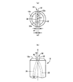
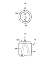
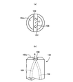
図6および図7は、このような流体供給穴付き加工工具の一例を説明する図で、それぞれシャンク100、102を示したもので、何れも工具軸心Oに対して対称的に一対の螺旋状の流体供給穴104、106が設けられており、(a) はシャンク100、102の後端面100a、102a側から見た端面図で、(b) は(a) の下方から見た正面図である。そして、図6のシャンク100は、その後端面100aに流体供給穴104、106の後端部がそのまま開口しているだけであるが、図7のシャンク102の後端面102aには、工具軸心Oに対して直交するとともに一対の流体供給穴104、106の後端開口部を通る一直線上に断面が矩形の連通溝108が設けられている。この連通溝108は、後端面102aとホルダ(図3の流体供給用工具ホルダ40など)との間の隙間が狭い場合でも、例えばホルダの中心部分に供給された流体を一対の流体供給穴104、106に導くためのもので、断面が半円弧形状等の連通溝が設けられることもある。
ところで、このような従来の流体供給穴付き加工工具においては、流体供給穴の後端開口部の開口面積と流体圧とによって質量流量(流速×断面積×密度)が定まる。すなわち、前記連通溝108の有無に拘らず、図6、図7において矢印Aで示すように、流体供給穴104、106の後端開口部に流体が流入するだけであるため、その開口面積と流体圧とによって質量流量が定まるのであり、より多くの流体を供給するためには流体供給穴104、106を大きくするか、流体圧を高くする必要がある。
By the way, in such a conventional machining tool with a fluid supply hole, the mass flow rate (flow velocity × cross-sectional area × density) is determined by the opening area of the rear end opening of the fluid supply hole and the fluid pressure. That is, regardless of the presence or absence of the
しかしながら、流体供給穴を大きくすると工具の強度が低下する一方、流体圧を高くしようとすると、流体供給装置の供給出力や各部の耐圧強度を高くする必要があり、コストが高くなるなどの問題があった。 However, when the fluid supply hole is enlarged, the strength of the tool is reduced. On the other hand, when the fluid pressure is increased, the supply output of the fluid supply device and the pressure resistance strength of each part need to be increased, which increases the cost. there were.
本発明は以上の事情を背景として為されたもので、その目的とするところは、流体供給穴を大きくしたり流体の供給圧力を高くしたりすることなく、流体が効率良く流体供給穴内に導入されるようにして流体の供給量を増大させることにある。 The present invention has been made against the background of the above circumstances, and the object of the present invention is to efficiently introduce the fluid into the fluid supply hole without enlarging the fluid supply hole or increasing the fluid supply pressure. In this way, the supply amount of the fluid is increased.
かかる目的を達成するために、第1発明は、円柱形状のシャンクと所定の加工を行う加工部とを同軸上に備えているとともに、工具軸方向に縦通するように流体供給穴が設けられ、前記シャンクの後端面に開口する後端開口部から導入された流体を前記加工部に供給する流体供給穴付き加工工具において、前記シャンクの後端面には、断面がV字形状で一対の平坦な側壁面を有するとともに、その側壁面の開口側の幅寸法(w1)が前記後端開口部の開口寸法よりも大きい流体導入溝が、その後端開口部と交差し且つその後端開口部が完全にその流体導入溝内に位置するように設けられていることを特徴とする。 In order to achieve such an object, the first invention is provided with a cylindrical shank and a machining portion for performing predetermined machining on the same axis, and is provided with a fluid supply hole so as to pass through in the tool axis direction. In the processing tool with a fluid supply hole for supplying the fluid introduced from the rear end opening that opens to the rear end surface of the shank to the processing portion, the rear end surface of the shank has a V-shaped cross section and a pair of flat surfaces. A fluid introduction groove having a side wall surface whose width dimension (w1) on the opening side of the side wall surface is larger than the opening size of the rear end opening intersects with the rear end opening and the rear end opening is completely It is provided so that it may be located in the fluid introduction groove | channel.
第2発明は、第1発明の流体供給穴付き加工工具において、前記一対の側壁面を接続する溝底の幅寸法(w2)が前記後端開口部の開口寸法よりも小さく、その後端開口部がその一対の側壁面の双方に跨がって開口するように前記流体導入溝が設けられていることを特徴とする。 According to a second invention, in the machining tool with fluid supply holes of the first invention, the width dimension (w2) of the groove bottom connecting the pair of side wall surfaces is smaller than the opening dimension of the rear end opening, and the rear end opening The fluid introduction groove is provided so as to open across both of the pair of side wall surfaces.
第3発明は、第1発明または第2発明の流体供給穴付き加工工具において、前記流体導入溝の前記一対の側壁面の開き角度(θ)は55°〜75°の範囲内であることを特徴とする。 According to a third invention, in the machining tool with a fluid supply hole of the first invention or the second invention, an opening angle (θ) of the pair of side wall surfaces of the fluid introduction groove is in a range of 55 ° to 75 °. Features.
第4発明は、第1発明〜第3発明の何れかの流体供給穴付き加工工具において、(a) 前記流体供給穴は工具軸心に対して対称的に一対設けられており、(b) 前記流体導入溝は、工具軸心に対して直交するとともに前記一対の流体供給穴の後端開口部を通る一直線上に設けられていることを特徴とする。 4th invention is a processing tool with a fluid supply hole in any one of 1st invention-3rd invention, (a) A pair of said fluid supply hole is provided symmetrically with respect to a tool axis, (b) The fluid introduction groove is provided on a straight line passing through the rear end openings of the pair of fluid supply holes while being orthogonal to the tool axis.
このような流体供給穴付き加工工具においては、断面がV字形状で一対の平坦な側壁面を有する流体導入溝が、流体供給穴の後端開口部と交差するように設けられているとともに、その流体導入溝の一対の側壁面の開口側の幅寸法(w1)は流体供給穴の後端開口部の開口寸法よりも大きく、流体供給穴の後端開口部が完全にその流体導入溝内に位置しているため、流体供給穴の開口寸法より大きい流体導入溝内の流体が一対の側壁面に案内されつつその流体供給穴の後端開口部内に導入されるようになる。これにより、流体供給穴を大きくしたり流体の供給圧力を高くしたりすることなく、流体が流体導入溝から効率良く流体供給穴内に導入されるようになり、加工部に対する流体の供給量が増大し、その流体によって得られる潤滑性能や冷却性能などが向上する。 In such a machining tool with a fluid supply hole, a fluid introduction groove having a V-shaped cross section and a pair of flat side wall surfaces is provided so as to intersect the rear end opening of the fluid supply hole, The width dimension (w1) on the opening side of the pair of side wall surfaces of the fluid introduction groove is larger than the opening dimension of the rear end opening part of the fluid supply hole, and the rear end opening part of the fluid supply hole is completely within the fluid introduction groove. Therefore, the fluid in the fluid introduction groove larger than the opening size of the fluid supply hole is introduced into the rear end opening of the fluid supply hole while being guided by the pair of side wall surfaces. As a result, the fluid can be efficiently introduced from the fluid introduction groove into the fluid supply hole without increasing the fluid supply hole or increasing the fluid supply pressure, and the amount of fluid supplied to the processing portion increases. In addition, the lubricating performance and cooling performance obtained by the fluid are improved.
第2発明では、一対の側壁面を接続する溝底の幅寸法(w2)が流体供給穴の後端開口部の開口寸法よりも小さく、その後端開口部が一対の側壁面の双方に跨がって開口するように流体導入溝が設けられているため、一対の側壁面に案内されつつ効率良く流体供給穴の後端開口部内に流体が導入されるようになり、加工部に対する流体の供給量が増大する。 In the second invention, the width dimension (w2) of the groove bottom connecting the pair of side wall surfaces is smaller than the opening dimension of the rear end opening portion of the fluid supply hole, and the rear end opening portion straddles both the pair of side wall surfaces. Since the fluid introduction groove is provided so as to open, the fluid is efficiently introduced into the rear end opening of the fluid supply hole while being guided by the pair of side wall surfaces, so that the fluid is supplied to the processing portion. The amount increases.
第3発明では、流体導入溝の一対の側壁面の開き角度(θ)が55°〜75°の範囲内であるため、一対の側壁面に案内されつつ効率良く流体供給穴の後端開口部内に流体が導入されるようになり、加工部に対する流体の供給量が増大する。 In the third aspect of the invention, since the opening angle (θ) of the pair of side wall surfaces of the fluid introduction groove is in the range of 55 ° to 75 °, the fluid supply hole is efficiently guided in the rear end opening of the fluid supply hole. As a result, fluid is introduced into the processing portion, and the amount of fluid supplied to the processing portion increases.
本発明の流体供給穴付き加工工具は、(a) 円柱形状のシャンクと、(b) 外周面に溝が設けられるとともに少なくとも工具軸方向の先端部に該溝に沿って切れ刃が形成されているボデーとを同軸上に有し、(c) 切れ刃の逃げ面に流体供給穴の先端開口部が開口しているドリルやエンドミル等の回転切削工具に好適に適用されるが、外周部に切れ刃が設けられたタップ等の他の切削工具や研削加工を行う砥石等の研削工具、或いは盛上げタップ等の転造工具などにも適用され得る。 The machining tool with a fluid supply hole of the present invention has (a) a cylindrical shank, (b) a groove is provided on the outer peripheral surface, and a cutting edge is formed along the groove at least at the tip in the tool axis direction. (C) It is preferably applied to a rotary cutting tool such as a drill or an end mill in which the tip opening of the fluid supply hole is open on the flank of the cutting edge. The present invention can also be applied to other cutting tools such as a tap provided with a cutting edge, a grinding tool such as a grindstone for grinding, or a rolling tool such as a raised tap.
流体供給穴は、工具軸心と平行な直線状の穴であっても良いし、工具軸心まわりにねじれた螺旋状の穴であっても良く、種々の態様が可能である。この流体供給穴は、工具軸心等に1本設けられるだけでも良いが、2本以上設けることも可能である。流体供給穴によって供給される流体は、潤滑作用や冷却作用などが得られる切削油剤や圧縮空気などである。 The fluid supply hole may be a straight hole parallel to the tool axis or may be a spiral hole twisted around the tool axis, and various modes are possible. Only one fluid supply hole may be provided in the tool axis or the like, but two or more fluid supply holes may be provided. The fluid supplied through the fluid supply hole is a cutting fluid or compressed air that can provide a lubricating action or a cooling action.
流体導入溝は、例えば工具軸心に対して直角に交差するように設けられるが、工具軸心と交差しないように設けられても良い。流体導入溝の一対の側壁面の開口側の幅寸法(w1)は、流体供給穴の後端開口部の開口寸法よりも大きければ良く、例えば流体供給穴の径寸法の2倍以上が望ましい。流体導入溝の溝底の幅寸法(w2)は、第2発明のように後端開口部の開口寸法よりも小さく、後端開口部が一対の側壁面の双方に跨がって開口するようにすることが望ましいが、第1発明の実施に際しては、後端開口部の開口寸法が溝底の幅寸法(w2)よりも小さく、その溝底のみに後端開口部が開口する場合でも良い。 The fluid introduction groove is provided, for example, so as to intersect at right angles to the tool axis, but may be provided so as not to intersect with the tool axis. The width dimension (w1) on the opening side of the pair of side wall surfaces of the fluid introduction groove only needs to be larger than the opening dimension of the rear end opening of the fluid supply hole, and for example, is preferably twice or more the diameter dimension of the fluid supply hole. The width dimension (w2) of the groove bottom of the fluid introduction groove is smaller than the opening dimension of the rear end opening as in the second aspect of the invention, and the rear end opening opens across both the pair of side wall surfaces. However, when the first invention is carried out, the opening dimension of the rear end opening may be smaller than the width dimension (w2) of the groove bottom, and the rear end opening may open only at the groove bottom. .
上記後端開口部の開口寸法は、例えば流体供給穴が工具軸心と平行な円穴の場合、その円穴の直径寸法である。流体供給穴がねじれ穴の場合、ねじれ角に応じて楕円形になるが、後端開口部と交差するように設けられる流体導入溝の幅方向と平行な方向の寸法が開口寸法で、幅寸法(w1)は、その幅方向の開口寸法よりも大きければ良く、第2発明の溝底の幅寸法(w2)は、その幅方向の開口寸法より小さければ良い。 For example, when the fluid supply hole is a circular hole parallel to the tool axis, the opening size of the rear end opening is the diameter of the circular hole. When the fluid supply hole is a torsion hole, it becomes an ellipse according to the twist angle, but the dimension in the direction parallel to the width direction of the fluid introduction groove provided to intersect the rear end opening is the opening dimension, and the width dimension (W1) should just be larger than the opening dimension of the width direction, and the width dimension (w2) of the groove bottom of 2nd invention should just be smaller than the opening dimension of the width direction.
流体導入溝の一対の側壁面の開き角度(θ)は、55°より小さいと開口側の幅寸法(w1)を十分に確保することが難しくなる一方、75°より大きいと後端開口部に対する流体の円滑な流入が損なわれるようになるため、55°〜75°の範囲内が望ましい。 If the opening angle (θ) of the pair of side wall surfaces of the fluid introduction groove is smaller than 55 °, it is difficult to sufficiently secure the width dimension (w1) on the opening side, whereas if it is larger than 75 °, the opening angle (θ1) with respect to the rear end opening portion. Since the smooth inflow of the fluid is impaired, the range of 55 ° to 75 ° is desirable.
以下、本発明の実施例を、図面を参照しつつ詳細に説明する。
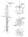
図1は、本発明の一実施例である流体供給穴付きドリル10(以下、単にドリル10という)を示す図で、(a) は工具軸心Oと直角な方向から見た正面図、(b) は後端部(図1(a) の上端部)を右方向から見て拡大して示す側面図、(c) は(b) の上方から見た後端面図、(d) は先端側(図1(a) の下方)から見て拡大して示す先端面図である。このドリル10は、2枚刃のツイストドリルで、円柱形状のシャンク12およびボデー14を同軸上に一体に備えており、ボデー14には工具軸心Oの右まわりにねじれた一対の溝16が工具軸心Oに対して対称的に形成されている。ボデー14の先端には、溝16の開口縁に沿って一対の切れ刃18が対称的に設けられており、シャンク12側から見て工具軸心Oの右まわりに回転駆動されることにより、それ等の切れ刃18によって穴を切削加工するとともに、切りくずが溝16を通ってシャンク12側へ排出される。本実施例では、一対の切れ刃18が設けられたボデー14の先端部分が加工部に相当する。
Hereinafter, embodiments of the present invention will be described in detail with reference to the drawings.
FIG. 1 is a view showing a
このドリル10は超硬合金にて構成されており、工具軸心Oまわりに所定のねじれ角(前記溝16と同じリード)でねじれた一対のオイルホール20、22が、工具軸心Oに対して対称的にシャンク12の後端からボデー14の先端まで軸方向に縦通するように設けられている。このオイルホール20、22は流体供給穴に相当し、断面が円形の円穴で、シャンク12の後端面12aに後端開口部20a、22aが開口している一方、前記切れ刃18の逃げ面24に先端開口部20b、22bが開口しており、後端開口部20a、22aから導入された流体(本実施例では切削油剤)を先端開口部20b、22bから吐出する。
The
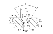
シャンク12の後端面12aは工具軸心Oに対して直角な平坦面で、外周部には所定の幅寸法でC面取り26が設けられているとともに、工具軸心Oと直交する一直線上に流体導入溝28が形成されており、後端開口部20a、22aは、その流体導入溝28の内部の中心線上であってC面取り26よりも内側の直径qの円周上に開口させられている。図2は、図1の(c) におけるII−II断面に相当する流体導入溝28の断面の拡大図で、この流体導入溝28は、断面が工具軸心Oに対して対称的なV字形状を成しており、一対の平坦な側壁面30、32を有するとともに、その一対の側壁面30、32の開き角度である溝開き角θは55°〜75°の範囲内で設定されている。また、一対の側壁面30、32の開口側の幅寸法すなわち溝開口幅w1は、後端開口部20a、22aの開口寸法(図2における左右方向の開口寸法)よりも大きく、その後端開口部20a、22aが完全に流体導入溝28内に位置するように設けられている。一対の側壁面30、32を接続する溝底34の幅寸法である溝底幅w2は、上記後端開口部20a、22aの開口寸法よりも小さく、その後端開口部20a、22aが一対の側壁面30、32の双方に跨がるように開口させられている。上記溝底34は、本実施例では半径Rの円弧形状を成している。
The
このような本実施例のドリル10の各部の寸法や角度は、例えば図4の(a) の本発明品の欄に示すように設定される。すなわち、シャンク12の径寸法が6mmの場合、オイルホール20、22の径寸法は0.7mm、穴位置径qは2.6mm、C面取り26の面取り量は0.7mm、流体導入溝28の溝開口幅w1は1.5mm、溝底幅w2は0.65mm、溝深さdは0.8mm、溝底半径Rは0.5mm、溝開き角θは65°とされる。
The dimensions and angles of the respective parts of the
そして、このようなドリル10は、例えば図3に示すような流体供給用工具ホルダ40によってシャンク12が保持されて用いられる。シャンク12には工具軸心Oと平行な平坦部36(図1参照)が設けられており、サイドロック用のねじ42がその平坦部36に締め付けられることにより、ドリル10は流体供給用工具ホルダ40に一体的に固定される。流体供給用工具ホルダ40は、図示しないマシニングセンタ等の主軸に装着されて回転駆動されるとともに、切削油剤を供給する流体供給路44を備えていて、切削油剤を所定の圧力でシャンク12の後端部に供給する。そして、このようにシャンク12の後端部に供給された切削油剤は、流体導入溝28から後端開口部20a、22a内に流入し、オイルホール20、22を流通して先端開口部20b、22bから吐出させられることにより、切れ刃18による穴明け加工部を潤滑する。
Such a
ここで、本実施例のドリル10は、断面がV字形状で一対の平坦な側壁面30、32を有する流体導入溝28が、オイルホール20、22の後端開口部20a、22aと交差するように設けられているとともに、その流体導入溝28の溝開口幅w1は後端開口部20a、22aの開口寸法よりも大きく、その後端開口部20a、22aが完全にその流体導入溝28内に位置しているため、図1の(b) に矢印Aで示すように、オイルホール20、22の開口寸法より大きい流体導入溝28内の切削油剤が一対の側壁面30、32に案内されつつそのオイルホール20、22の後端開口部20a、22a内に導入されるようになる。これにより、オイルホール20、22を大きくしたり切削油剤の供給圧力を高くしたりすることなく、切削油剤が流体導入溝28から効率良くオイルホール20、22内に導入されるようになり、穴明け加工部に対する切削油剤の供給量が増大し、その切削油剤によって得られる潤滑性能や冷却性能が向上する。
Here, in the
また、本実施例では、溝底幅w2がオイルホール20、22の後端開口部20a、22aの開口寸法よりも小さく、その後端開口部20a、22aが一対の側壁面30、32の双方に跨がるように開口しているとともに、溝開き角θが55°〜75°の範囲内であるため、一対の側壁面30、32に案内されつつ一層効率良く後端開口部20a、22a内に切削油剤が導入されるようになり、穴明け加工部に対する切削油剤の供給量が増大して潤滑性能や冷却性能が更に向上する。
Further, in this embodiment, the groove bottom width w2 is smaller than the opening size of the
次に、図4の(a) に示す本発明品および前記流体導入溝28が設けられていない従来品について、CAE(Computer Aided Engineering) により(b) に示す項目について解析を行った結果を説明する。図4の(b) の「到達時間」は、切削油剤の供給を開始してから先端開口部20b、22bに切削油剤が到達するまでの所要時間で、「安定時間」は、先端開口部20b、22bから吐出される切削油剤の吐出量が略一定になるまでの所要時間である。なお、ここでは計算を簡略化するため、一対のオイルホール20、22が工具軸心Oと平行に一直線に設けられた場合を想定して解析を行った。
Next, the results of analyzing the items shown in (b) by CAE (Computer Aided Engineering) for the product of the present invention shown in (a) of FIG. 4 and the conventional product not provided with the
上記図4の(b) の解析結果から、本発明品は従来品に比較して流速および密度が大きく、質量流量比(質量流量/断面積=流速×密度)が2〜3倍になり、潤滑性能や冷却性能の大幅な向上が期待できる。また、先端開口部20b、22bに切削油剤が達するまでの到達時間や安定時間も早くなり、安定した潤滑性能や冷却性能が速やかに得られるようになる。
From the analysis result of FIG. 4 (b) above, the product of the present invention has a larger flow velocity and density than the conventional product, and the mass flow ratio (mass flow rate / cross-sectional area = flow velocity × density) is 2 to 3 times. A significant improvement in lubrication performance and cooling performance can be expected. In addition, the arrival time and the stabilization time until the cutting fluid reaches the
なお、前記実施例では流体導入溝28の溝底34が円弧形状を成していたが、図5に示す流体導入溝50のように溝底52を平坦面とすることも可能である。この溝底52と一対の側壁面30、32とが接続されるコーナーは、加工が可能な範囲で角張っていても良いが、所定の面取りRを設けるようにしても良い。
In the above-described embodiment, the
以上、本発明の実施例を図面に基づいて詳細に説明したが、これ等はあくまでも一実施形態であり、本発明は当業者の知識に基づいて種々の変更、改良を加えた態様で実施することができる。 As mentioned above, although the Example of this invention was described in detail based on drawing, these are one Embodiment to the last, This invention is implemented in the aspect which added the various change and improvement based on the knowledge of those skilled in the art. be able to.
10:流体供給穴付きドリル(流体供給穴付き加工工具) 12:シャンク 12a:後端面 18:切れ刃(加工部) 20、22:オイルホール(流体供給穴) 20a、22a:後端開口部 28、50:流体導入溝 30、32:側壁面 34、52:溝底 O:工具軸心 w1:溝開口幅(開口側の幅寸法) w2:溝底幅(溝底の幅寸法) θ:溝開き角(開き角度)
10: Drill with fluid supply hole (processing tool with fluid supply hole) 12:
Claims (4)
前記シャンクの後端面には、断面がV字形状で一対の平坦な側壁面を有するとともに、該側壁面の開口側の幅寸法(w1)が前記後端開口部の開口寸法よりも大きい流体導入溝が、該後端開口部と交差し且つ該後端開口部が完全に該流体導入溝内に位置するように設けられている
ことを特徴とする流体供給穴付き加工工具。 A rear end opening that is provided with a cylindrical shank and a processing portion for performing predetermined processing on the same axis, and is provided with a fluid supply hole so as to extend vertically in the tool axis direction, and opens to the rear end surface of the shank. In the processing tool with a fluid supply hole for supplying the fluid introduced from to the processing unit,
The rear end surface of the shank has a V-shaped cross section and a pair of flat side wall surfaces, and the width dimension (w1) on the opening side of the side wall surface is larger than the opening dimension of the rear end opening portion. A machining tool with a fluid supply hole, characterized in that the groove is provided so as to intersect the rear end opening and the rear end opening is completely located in the fluid introduction groove.
ことを特徴とする請求項1に記載の流体供給穴付き加工工具。 The width dimension (w2) of the groove bottom connecting the pair of side wall surfaces is smaller than the opening size of the rear end opening, and the rear end opening opens across both of the pair of side wall surfaces. The processing tool with a fluid supply hole according to claim 1, wherein the fluid introduction groove is provided in the processing tool.
ことを特徴とする請求項1または2に記載の流体供給穴付き加工工具。 The opening angle (θ) of the pair of side wall surfaces of the fluid introduction groove is within a range of 55 ° to 75 °. The machining tool with a fluid supply hole according to claim 1 or 2, wherein:
前記流体導入溝は、工具軸心に対して直交するとともに前記一対の流体供給穴の後端開口部を通る一直線上に設けられている
ことを特徴とする請求項1〜3の何れか1項に記載の流体供給穴付き加工工具。 A pair of the fluid supply holes are provided symmetrically with respect to the tool axis,
4. The fluid introduction groove according to claim 1, wherein the fluid introduction groove is provided on a straight line that is orthogonal to the tool axis and passes through rear end openings of the pair of fluid supply holes. A machining tool with a fluid supply hole as described in 1.
Priority Applications (1)
| Application Number | Priority Date | Filing Date | Title |
|---|---|---|---|
| JP2008231580A JP5090297B2 (en) | 2008-09-09 | 2008-09-09 | Machining tool with fluid supply hole |
Applications Claiming Priority (1)
| Application Number | Priority Date | Filing Date | Title |
|---|---|---|---|
| JP2008231580A JP5090297B2 (en) | 2008-09-09 | 2008-09-09 | Machining tool with fluid supply hole |
Publications (2)
| Publication Number | Publication Date |
|---|---|
| JP2010064171A true JP2010064171A (en) | 2010-03-25 |
| JP5090297B2 JP5090297B2 (en) | 2012-12-05 |
Family
ID=42190210
Family Applications (1)
| Application Number | Title | Priority Date | Filing Date |
|---|---|---|---|
| JP2008231580A Active JP5090297B2 (en) | 2008-09-09 | 2008-09-09 | Machining tool with fluid supply hole |
Country Status (1)
| Country | Link |
|---|---|
| JP (1) | JP5090297B2 (en) |
Cited By (1)
| Publication number | Priority date | Publication date | Assignee | Title |
|---|---|---|---|---|
| CN112496671A (en) * | 2020-11-30 | 2021-03-16 | 中复连众(哈密)复合材料有限公司 | Installation method of megawatt wind turbine blade lightning receptor copper disc |
-
2008
- 2008-09-09 JP JP2008231580A patent/JP5090297B2/en active Active
Cited By (2)
| Publication number | Priority date | Publication date | Assignee | Title |
|---|---|---|---|---|
| CN112496671A (en) * | 2020-11-30 | 2021-03-16 | 中复连众(哈密)复合材料有限公司 | Installation method of megawatt wind turbine blade lightning receptor copper disc |
| CN112496671B (en) * | 2020-11-30 | 2022-01-25 | 中复连众(沈阳)复合材料有限公司 | Installation method of megawatt wind turbine blade lightning receptor copper disc |
Also Published As
| Publication number | Publication date |
|---|---|
| JP5090297B2 (en) | 2012-12-05 |
Similar Documents
| Publication | Publication Date | Title |
|---|---|---|
| JP5447129B2 (en) | Drill with coolant hole | |
| US7789599B2 (en) | Drill | |
| KR101455582B1 (en) | Chip suction solid drill | |
| KR102082123B1 (en) | Drill | |
| KR101740840B1 (en) | Drill | |
| US7909545B2 (en) | Ballnose end mill | |
| US7278806B1 (en) | Two edge deburring tool | |
| US7320566B2 (en) | Cutting tool including detachable cutter head | |
| WO2011132686A1 (en) | Gun drill | |
| EP0841115A1 (en) | Elongated drill with replaceable cutting inserts | |
| JP2017109274A (en) | drill | |
| WO2018206400A1 (en) | Drill body and drill | |
| US6283682B1 (en) | Helically fluted twist drill device | |
| JP5090297B2 (en) | Machining tool with fluid supply hole | |
| JP2008178941A (en) | Drill unit, and drill and holder used in the drill unit | |
| JP2007136563A (en) | Insert type drill | |
| EP3401043A1 (en) | Drill body and drill | |
| JP7400311B2 (en) | Drill | |
| JP2003117710A (en) | Drilling tool with coolant hole | |
| JP7434791B2 (en) | Drill | |
| JP2005034976A (en) | Cutting tool | |
| JP4954044B2 (en) | drill | |
| WO2016183064A1 (en) | Drill bit | |
| JP2005205526A (en) | Deep hole boring tool | |
| JP2023059519A (en) | Drill |
Legal Events
| Date | Code | Title | Description |
|---|---|---|---|
| A621 | Written request for application examination |
Free format text: JAPANESE INTERMEDIATE CODE: A621 Effective date: 20100426 |
|
| A977 | Report on retrieval |
Free format text: JAPANESE INTERMEDIATE CODE: A971007 Effective date: 20120706 |
|
| A131 | Notification of reasons for refusal |
Free format text: JAPANESE INTERMEDIATE CODE: A131 Effective date: 20120710 |
|
| A521 | Request for written amendment filed |
Free format text: JAPANESE INTERMEDIATE CODE: A523 Effective date: 20120803 |
|
| TRDD | Decision of grant or rejection written | ||
| A01 | Written decision to grant a patent or to grant a registration (utility model) |
Free format text: JAPANESE INTERMEDIATE CODE: A01 Effective date: 20120821 |
|
| A01 | Written decision to grant a patent or to grant a registration (utility model) |
Free format text: JAPANESE INTERMEDIATE CODE: A01 |
|
| A61 | First payment of annual fees (during grant procedure) |
Free format text: JAPANESE INTERMEDIATE CODE: A61 Effective date: 20120912 |
|
| FPAY | Renewal fee payment (event date is renewal date of database) |
Free format text: PAYMENT UNTIL: 20150921 Year of fee payment: 3 |
|
| R150 | Certificate of patent or registration of utility model |
Ref document number: 5090297 Country of ref document: JP Free format text: JAPANESE INTERMEDIATE CODE: R150 Free format text: JAPANESE INTERMEDIATE CODE: R150 |
|
| R250 | Receipt of annual fees |
Free format text: JAPANESE INTERMEDIATE CODE: R250 |
|
| R250 | Receipt of annual fees |
Free format text: JAPANESE INTERMEDIATE CODE: R250 |
|
| R250 | Receipt of annual fees |
Free format text: JAPANESE INTERMEDIATE CODE: R250 |
|
| R250 | Receipt of annual fees |
Free format text: JAPANESE INTERMEDIATE CODE: R250 |
|
| R250 | Receipt of annual fees |
Free format text: JAPANESE INTERMEDIATE CODE: R250 |