JP2010064068A - Gas-liquid separator and substrate processing apparatus including the same - Google Patents
Gas-liquid separator and substrate processing apparatus including the same Download PDFInfo
- Publication number
- JP2010064068A JP2010064068A JP2009208934A JP2009208934A JP2010064068A JP 2010064068 A JP2010064068 A JP 2010064068A JP 2009208934 A JP2009208934 A JP 2009208934A JP 2009208934 A JP2009208934 A JP 2009208934A JP 2010064068 A JP2010064068 A JP 2010064068A
- Authority
- JP
- Japan
- Prior art keywords
- gas
- liquid
- separation box
- filter
- substrate
- Prior art date
- Legal status (The legal status is an assumption and is not a legal conclusion. Google has not performed a legal analysis and makes no representation as to the accuracy of the status listed.)
- Granted
Links
- 239000007788 liquid Substances 0.000 title claims abstract description 217
- 238000012545 processing Methods 0.000 title claims abstract description 74
- 239000000758 substrate Substances 0.000 title claims abstract description 64
- 238000000926 separation method Methods 0.000 claims abstract description 111
- 239000000203 mixture Substances 0.000 claims abstract description 7
- 238000000034 method Methods 0.000 claims description 61
- 238000002347 injection Methods 0.000 claims description 22
- 239000007924 injection Substances 0.000 claims description 22
- 238000007789 sealing Methods 0.000 claims description 8
- 238000005192 partition Methods 0.000 claims description 7
- 238000003780 insertion Methods 0.000 claims description 6
- 230000037431 insertion Effects 0.000 claims description 6
- 239000000835 fiber Substances 0.000 claims description 4
- 238000007599 discharging Methods 0.000 abstract description 2
- 239000007789 gas Substances 0.000 description 56
- 238000012546 transfer Methods 0.000 description 8
- 230000002093 peripheral effect Effects 0.000 description 6
- 238000004140 cleaning Methods 0.000 description 5
- 238000010586 diagram Methods 0.000 description 5
- 238000005530 etching Methods 0.000 description 5
- VEXZGXHMUGYJMC-UHFFFAOYSA-N Hydrochloric acid Chemical compound Cl VEXZGXHMUGYJMC-UHFFFAOYSA-N 0.000 description 4
- 238000009434 installation Methods 0.000 description 4
- 239000004973 liquid crystal related substance Substances 0.000 description 4
- KRHYYFGTRYWZRS-UHFFFAOYSA-N Fluorane Chemical compound F KRHYYFGTRYWZRS-UHFFFAOYSA-N 0.000 description 3
- 230000000903 blocking effect Effects 0.000 description 3
- 238000001914 filtration Methods 0.000 description 3
- 239000011148 porous material Substances 0.000 description 3
- 239000004743 Polypropylene Substances 0.000 description 2
- QAOWNCQODCNURD-UHFFFAOYSA-N Sulfuric acid Chemical compound OS(O)(=O)=O QAOWNCQODCNURD-UHFFFAOYSA-N 0.000 description 2
- 230000000694 effects Effects 0.000 description 2
- 238000007667 floating Methods 0.000 description 2
- 239000011521 glass Substances 0.000 description 2
- 238000012423 maintenance Methods 0.000 description 2
- 238000004519 manufacturing process Methods 0.000 description 2
- 239000000463 material Substances 0.000 description 2
- 238000012986 modification Methods 0.000 description 2
- 230000004048 modification Effects 0.000 description 2
- 239000004065 semiconductor Substances 0.000 description 2
- 239000007921 spray Substances 0.000 description 2
- 229920002449 FKM Polymers 0.000 description 1
- MHAJPDPJQMAIIY-UHFFFAOYSA-N Hydrogen peroxide Chemical compound OO MHAJPDPJQMAIIY-UHFFFAOYSA-N 0.000 description 1
- 230000002378 acidificating effect Effects 0.000 description 1
- 230000003247 decreasing effect Effects 0.000 description 1
- 238000002242 deionisation method Methods 0.000 description 1
- 238000005137 deposition process Methods 0.000 description 1
- 238000013461 design Methods 0.000 description 1
- 238000007689 inspection Methods 0.000 description 1
- QPJSUIGXIBEQAC-UHFFFAOYSA-N n-(2,4-dichloro-5-propan-2-yloxyphenyl)acetamide Chemical compound CC(C)OC1=CC(NC(C)=O)=C(Cl)C=C1Cl QPJSUIGXIBEQAC-UHFFFAOYSA-N 0.000 description 1
- 239000004745 nonwoven fabric Substances 0.000 description 1
- 230000003647 oxidation Effects 0.000 description 1
- 238000007254 oxidation reaction Methods 0.000 description 1
- 238000000206 photolithography Methods 0.000 description 1
- -1 polypropylene Polymers 0.000 description 1
- 229920001155 polypropylene Polymers 0.000 description 1
- 238000011084 recovery Methods 0.000 description 1
- 229920006395 saturated elastomer Polymers 0.000 description 1
- 229910052710 silicon Inorganic materials 0.000 description 1
- 239000010703 silicon Substances 0.000 description 1
- 239000000243 solution Substances 0.000 description 1
- 238000005507 spraying Methods 0.000 description 1
- 239000000126 substance Substances 0.000 description 1
- 239000010409 thin film Substances 0.000 description 1
Images


Classifications
-
- H—ELECTRICITY
- H01—ELECTRIC ELEMENTS
- H01L—SEMICONDUCTOR DEVICES NOT COVERED BY CLASS H10
- H01L21/00—Processes or apparatus adapted for the manufacture or treatment of semiconductor or solid state devices or of parts thereof
- H01L21/67—Apparatus specially adapted for handling semiconductor or electric solid state devices during manufacture or treatment thereof; Apparatus specially adapted for handling wafers during manufacture or treatment of semiconductor or electric solid state devices or components ; Apparatus not specifically provided for elsewhere
- H01L21/67005—Apparatus not specifically provided for elsewhere
- H01L21/67011—Apparatus for manufacture or treatment
- H01L21/67017—Apparatus for fluid treatment
- H01L21/67028—Apparatus for fluid treatment for cleaning followed by drying, rinsing, stripping, blasting or the like
- H01L21/6704—Apparatus for fluid treatment for cleaning followed by drying, rinsing, stripping, blasting or the like for wet cleaning or washing
-
- B—PERFORMING OPERATIONS; TRANSPORTING
- B01—PHYSICAL OR CHEMICAL PROCESSES OR APPARATUS IN GENERAL
- B01D—SEPARATION
- B01D19/00—Degasification of liquids
- B01D19/0042—Degasification of liquids modifying the liquid flow
- B01D19/0052—Degasification of liquids modifying the liquid flow in rotating vessels, vessels containing movable parts or in which centrifugal movement is caused
- B01D19/0057—Degasification of liquids modifying the liquid flow in rotating vessels, vessels containing movable parts or in which centrifugal movement is caused the centrifugal movement being caused by a vortex, e.g. using a cyclone, or by a tangential inlet
-
- B—PERFORMING OPERATIONS; TRANSPORTING
- B01—PHYSICAL OR CHEMICAL PROCESSES OR APPARATUS IN GENERAL
- B01D—SEPARATION
- B01D53/00—Separation of gases or vapours; Recovering vapours of volatile solvents from gases; Chemical or biological purification of waste gases, e.g. engine exhaust gases, smoke, fumes, flue gases, aerosols
- B01D53/34—Chemical or biological purification of waste gases
- B01D53/74—General processes for purification of waste gases; Apparatus or devices specially adapted therefor
- B01D53/77—Liquid phase processes
- B01D53/78—Liquid phase processes with gas-liquid contact
-
- H—ELECTRICITY
- H01—ELECTRIC ELEMENTS
- H01L—SEMICONDUCTOR DEVICES NOT COVERED BY CLASS H10
- H01L21/00—Processes or apparatus adapted for the manufacture or treatment of semiconductor or solid state devices or of parts thereof
- H01L21/67—Apparatus specially adapted for handling semiconductor or electric solid state devices during manufacture or treatment thereof; Apparatus specially adapted for handling wafers during manufacture or treatment of semiconductor or electric solid state devices or components ; Apparatus not specifically provided for elsewhere
- H01L21/67005—Apparatus not specifically provided for elsewhere
- H01L21/67011—Apparatus for manufacture or treatment
- H01L21/67017—Apparatus for fluid treatment
- H01L21/67063—Apparatus for fluid treatment for etching
- H01L21/67075—Apparatus for fluid treatment for etching for wet etching
Abstract
Description
本発明は、気液分離装置及びこれを含む基板処理装置に関し、より詳細には、基板を処理するための処理液とガスとの混合された気液を排出させる時、前記気液から前記処理液と前記ガスとを分離させることができる分離装置及びこの分離装置を含んで前記基板を処理する処理装置に関する。 The present invention relates to a gas-liquid separation device and a substrate processing apparatus including the same, and more specifically, when discharging a gas-liquid mixed with a processing liquid and a gas for processing a substrate, the processing is performed from the gas-liquid. The present invention relates to a separation apparatus that can separate a liquid and the gas and a processing apparatus that includes the separation apparatus and processes the substrate.
一般的に、平板表示装置は、液晶を用いる液晶表示装置(LCD)、プラズマを用いるプラズマ表示装置(PDP)、有機発光素子を用いる有機発光表示装置(OLED)等が挙げられる。 In general, examples of the flat panel display include a liquid crystal display (LCD) using liquid crystal, a plasma display (PDP) using plasma, and an organic light emitting display (OLED) using an organic light emitting element.
このような前記平板表示装置は、実質的に画像を表示する表示パネルを含む。前記表示パネルは、ガラス材質の基板に基づいて製造される。
具体的に、前記表示パネルは、前記基板を対象とする蒸着工程、エッチング工程、フォトリソグラフィ工程、洗浄工程、検査工程などを行って製造される。
The flat panel display device includes a display panel that substantially displays an image. The display panel is manufactured based on a glass substrate.
Specifically, the display panel is manufactured by performing a deposition process, an etching process, a photolithography process, a cleaning process, an inspection process, and the like for the substrate.
前記のような工程のうち、エッチング工程及び洗浄工程は、工程チャンバー内に前記基板を配置させた後、前記工程チャンバーに前記エッチング工程または前記洗浄工程のための処理液を処理液噴射部を通じて、前記基板に噴射することによって進行される。 Among the processes described above, the etching process and the cleaning process include arranging the substrate in a process chamber, and then supplying a processing liquid for the etching process or the cleaning process to the process chamber through a processing liquid injection unit. It proceeds by spraying onto the substrate.
この際、前記処理液噴射部の上部には、前記処理液を前記基板に誘導するために前記基板にガスを噴射するガス噴射部が配置される。この場合、前記工程チャンバーの内部には、前記処理液と前記ガスとの混合された噴霧形態の気液が存在するようになる。 At this time, a gas injection unit for injecting a gas to the substrate is arranged above the processing liquid injection unit in order to guide the processing liquid to the substrate. In this case, a gas-liquid in a spray form in which the processing liquid and the gas are mixed exists in the process chamber.
これによって、噴霧形態の前記気液は、前記工程チャンバーで浮遊して他の前記基板を汚染させるおそれがあるため、前記工程チャンバーには外部の真空ポンプから真空圧が伝達される流入管が連結され、前記気液を前記真空圧を通じて外部に吸入させる。 As a result, the gas-liquid in a spray form may float in the process chamber and contaminate other substrates. Therefore, an inflow pipe to which a vacuum pressure is transmitted from an external vacuum pump is connected to the process chamber. The gas-liquid is sucked to the outside through the vacuum pressure.
しかし、前記気液がそのまま前記真空ポンプに流入される場合、前記気液のうち、前記処理液によって前記真空ポンプが破損するおそれがある。 However, when the gas / liquid flows into the vacuum pump as it is, the vacuum pump may be damaged by the processing liquid out of the gas / liquid.
そこで、本発明は、前記問題に鑑みてなされたものであり、本発明の目的とするところは、気液から処理液とガスとを簡単に分離することが可能な、新規かつ改良された気液分離装置を提供することにある。 Accordingly, the present invention has been made in view of the above problems, and an object of the present invention is to provide a new and improved gas that can easily separate a processing liquid and a gas from a gas and liquid. The object is to provide a liquid separation device.
前述した本発明の目的を達成するために、一特徴による気液分離装置は、分離箱、フィルター部、排気管、及び排水管を含む。前記分離箱は、上部に気液の流入される流入口が形成される。前記フィルター部は、前記分離箱の内部で前記流入口の下部に配置され、前記流入された気液から液体成分をフィルタリングする。前記排気管は、閉められた上部が前記フィルター部と向い合って前記分離箱の下部に連結され、側面に前記フィルター部を通過した前記気液の気体成分を排気させるための少なくとも一つの排気口が形成される。前記排水管は、前記排気管と隣接した前記分離箱の下部に連結され、前記フィルター部でフィルタリングされた前記気液の液体成分を排水させる。 In order to achieve the above-described object of the present invention, a gas-liquid separator according to one aspect includes a separation box, a filter unit, an exhaust pipe, and a drain pipe. The separation box is formed with an inflow port through which gas and liquid are introduced. The filter unit is disposed in the lower part of the inflow port inside the separation box, and filters a liquid component from the inflowed gas / liquid. The exhaust pipe is connected to the lower part of the separation box with the closed upper part facing the filter part, and at least one exhaust port for exhausting the gas component of the gas-liquid that has passed through the filter part on the side surface Is formed. The drain pipe is connected to a lower part of the separation box adjacent to the exhaust pipe, and drains the liquid component of the gas-liquid filtered by the filter unit.
ここで、前記排気口は、前記分離箱の下部の底面より高く位置することができる。
前記フィルター部は、前記分離箱の内部に隔壁構造に配置されて第1ホールの形成された第1多孔板と、前記分離箱の内部で前記第1多孔板の下部に隔壁構造に配置され、前記第1ホールより小さい直径を有する第2ホールの形成された第2多孔板と、を含む。
Here, the exhaust port may be positioned higher than the bottom surface of the lower part of the separation box.
The filter unit is disposed in a partition structure inside the separation box and has a first porous plate having a first hole formed therein, and is disposed in the partition structure in the separation box and below the first porous plate. A second perforated plate having a second hole having a smaller diameter than the first hole.
これによって、前記第1ホールと前記第2ホールは、それぞれ全体面積が前記流入口の面積に対して1:1.1〜1:1.5及び1:1〜1:1.2の比率を有するように形成されることが可能である。 Accordingly, the first hole and the second hole respectively have a ratio of 1: 1.1 to 1: 1.5 and 1: 1 to 1: 1.2 with respect to the area of the inlet. It can be formed to have.
また、前記第1ホールは、前記流入口の直径に対して1:0.1〜1:0.3の直径を有し、前記第2ホールは、前記第1ホールの直径に対して1:0.7〜1:0.9の直径を有することができる。 The first hole may have a diameter of 1: 0.1 to 1: 0.3 with respect to the diameter of the inlet, and the second hole may have a diameter of 1: 0.1 with respect to the diameter of the first hole. It can have a diameter of 0.7-1: 0.9.
また、前記フィルター部は、前記第1及び第2多孔板の間に繊維糸からなる少なくとも一枚のフィルターシートを更に含むことができる。
一方、前記分離箱は、前記第1及び第2多孔板と前記フィルターシートとの挿入及び分離が可能であるように第1側部に開口部が形成されることが可能である。
The filter unit may further include at least one filter sheet made of fiber yarn between the first and second perforated plates.
Meanwhile, the separation box may have an opening at a first side so that the first and second perforated plates and the filter sheet can be inserted and separated.
これに、前記気液分離装置は、前記開口部をカバーするカバー部と、前記カバー部と前記分離箱との間をシーリングするシーリング部と、を更に含むことができる。
また、前記分離箱は、前記開口部の内側に前記第1及び第2多孔板それぞれの挿入方向に長く形成され、前記第1及び第2多孔板それぞれの挿入をガイドする第1及び第2ガイド溝を有することができる。
In addition, the gas-liquid separator may further include a cover portion that covers the opening, and a sealing portion that seals between the cover portion and the separation box.
In addition, the separation box is formed long inside the opening in the insertion direction of the first and second perforated plates, and the first and second guides guide the insertion of the first and second perforated plates. Can have grooves.
ここで、前記第1及び第2ガイド溝のそれぞれの幅は、挿入の行われる前記第1及び第2多孔板のそれぞれの厚さよりそれぞれ1〜3mm広いこともある。
一方、前記分離箱は、下部の底面に周囲より低く形成された段差部を有し、前記排水管は、前記段差部に連結されることが可能である。
Here, the width of each of the first and second guide grooves may be 1 to 3 mm wider than the thickness of each of the first and second perforated plates to be inserted.
On the other hand, the separation box has a step portion formed at a lower bottom surface lower than the surroundings, and the drain pipe can be connected to the step portion.
これとは違って、前記分離箱は、下部の底面が前記第2側部に傾くように形成され、前記排水管は、前記底面の前記第2側部と接する部位に連結されることが可能である。
また、前記排気管は、円周方向に排気口を含み、前記排気口の間の間隔は、前記排気管の円周に対して1:0.07〜1:0.1を有するように複数が形成されることが可能である。
In contrast, the separation box may be formed such that a bottom surface of the lower portion is inclined toward the second side portion, and the drain pipe may be connected to a portion of the bottom surface that contacts the second side portion. It is.
The exhaust pipe includes exhaust ports in a circumferential direction, and a plurality of intervals between the exhaust ports have a range of 1: 0.07 to 1: 0.1 with respect to the circumference of the exhaust pipe. Can be formed.
前述した本発明の他の目的を達成するために、一特徴による基板処理装置は、工程チャンバー、処理液噴射部、ガス噴射部、及び気液分離部を含む。前記工程チャンバーは、基板を処理するための空間を提供する。前記処理液噴射部は、前記工程チャンバーの内部で前記基板の上部に配置され、外部から供給される処理液を前記基板に噴射する。前記ガス噴射部は、前記処理液噴射部の上部に配置され、前記工程チャンバーに全体的にガスを噴射する。前記気液分離部は、前記工程チャンバーと隣接するように配置され、前記工程チャンバーの上部と流入管を通じて連結され、前記工程チャンバーの内部から前記処理液と前記ガスとの混合された気液が流入され、前記流入された気液から前記処理液と前記ガスとを分離させる。 In order to achieve another object of the present invention, a substrate processing apparatus according to one aspect includes a process chamber, a processing liquid injection unit, a gas injection unit, and a gas-liquid separation unit. The process chamber provides a space for processing a substrate. The treatment liquid ejecting unit is disposed on the substrate inside the process chamber, and ejects a treatment liquid supplied from the outside onto the substrate. The gas injection unit is disposed on the processing liquid injection unit and injects gas into the process chamber as a whole. The gas-liquid separation unit is disposed adjacent to the process chamber, and is connected to the upper part of the process chamber through an inflow pipe, and a gas-liquid mixture of the processing liquid and the gas from the inside of the process chamber. Inflowing, the processing liquid and the gas are separated from the inflowing gas-liquid.
これに、前記気液分離部は、上部に前記流入管が連結され、前記気液の流入される分離箱、前記分離箱の内部で前記流入管の下部に配置されて前記流入された気液から前記処理液をフィルタリングするフィルター部、閉められた上部が前記フィルター部と向い合って前記分離箱の下部に連結され、側面に前記気液のうち、前記フィルター部を通過した前記ガスを排気させるための少なくとも一つの排気口が形成された排気管、及び前記排気管と隣接した前記分離箱の下部に連結され、前記フィルター部でフィルタリングされた処理液を排水させる第1排水管、を含む。 The gas-liquid separator is connected to the inflow pipe at an upper portion thereof, a separation box into which the gas-liquid is introduced, and the gas-liquid that is disposed in the lower portion of the inflow pipe inside the separation box. A filter part for filtering the treatment liquid from the closed part, the closed upper part faces the filter part and is connected to the lower part of the separation box, and the side of the gas liquid that has passed through the filter part is exhausted on the side surface And a first drain pipe connected to a lower part of the separation box adjacent to the exhaust pipe and draining the processing liquid filtered by the filter unit.
一方、前記基板処理装置は、前記排気管の前記分離箱と反対側に連結され、前記分離箱を通じて前記流入管に真空圧を提供する真空ポンプを更に含むことができる。
また、前記基板処理装置は、前記工程チャンバーの下部に連結され、前記基板を処理して前記工程チャンバーの下部に誘導される処理液を排水させる第2排水管を更に含む。この場合、前記第1排水管は、前記第2排水管に連結されて前記フィルタリングされた処理液を前記第2排水管に排水させることができる。
Meanwhile, the substrate processing apparatus may further include a vacuum pump connected to the exhaust pipe opposite to the separation box and providing a vacuum pressure to the inflow pipe through the separation box.
The substrate processing apparatus may further include a second drain pipe connected to a lower portion of the process chamber and processing the substrate to drain a processing liquid guided to the lower portion of the process chamber. In this case, the first drain pipe can be connected to the second drain pipe to drain the filtered processing liquid to the second drain pipe.
このような気液分離装置及びこれを含む基板処理装置によると、工程チャンバーと真空ポンプとの間に気液から液体成分の処理液を分離できる前記気液分離装置を配置することによって、前記気液のうち、処理液によって前記真空ポンプが破損することを防止することができる。 According to such a gas-liquid separator and a substrate processing apparatus including the gas-liquid separator, the gas-liquid separator that can separate the liquid processing liquid from the gas-liquid is disposed between the process chamber and the vacuum pump. Among the liquids, the vacuum pump can be prevented from being damaged by the processing liquid.
また、前記気液分離装置のフィルター部の第1及び第2多孔板とフィルターシートの上下配置を通じて、前記気液の流れを下部方向にほぼ維持させながら前記気液から前記処理液を分離させた後、排気管の側面に形成された排気口を通じて、前記気液の気体成分のガスを排気させることによって、前記分離箱のサイズが大きくなることを防止することができる。即ち、前記気液分離装置の設置空間を最小化することによって、周囲の他の装置の設置を容易にすることができる。 In addition, the processing liquid is separated from the gas-liquid while maintaining the flow of the gas-liquid substantially in the lower direction through the upper and lower arrangements of the first and second perforated plates and the filter sheet of the filter portion of the gas-liquid separator. After that, the gas of the gas component of the gas-liquid is exhausted through the exhaust port formed on the side surface of the exhaust pipe, thereby preventing the separation box from increasing in size. That is, by minimizing the installation space for the gas-liquid separation device, it is possible to facilitate the installation of other peripheral devices.
また、前記気液分離装置で長時間の使用時、交替が要求される前記フィルター部のフィルターシートを前記分離箱の開口部を通じて簡単に挿入及び分離させることによって、前記フィルターシートの交替を簡単に行うことができる。即ち、前記フィルターシートの維持保守の作業を容易に行うことができる。 In addition, when the gas-liquid separator is used for a long time, the filter sheet of the filter unit that requires replacement can be easily inserted and separated through the opening of the separation box, thereby easily replacing the filter sheet. It can be carried out. That is, the maintenance work of the filter sheet can be easily performed.
以下、添付した図面を参照して、本発明の実施例による気液分離装置及びこれを含む基板処理装置について詳細に説明する。本発明は多様に変更することができ、多様な形態を有することができること、特定の実施形態を図面に例示して本文に詳細に説明する。しかし、これは、本発明を特定の開示形態に限定するのではなく、本発明の思想及び技術範囲に含まれる全ての変更、均等物、乃至代替物を含むことを理解すべきである。各図面を説明しながら類似の参照符号を類似の構成要素に対して付与した。図面において、構造物の寸法は本発明の明確性のために実際より拡大して示した。 Hereinafter, a gas-liquid separator and a substrate processing apparatus including the same according to embodiments of the present invention will be described in detail with reference to the accompanying drawings. The present invention can be variously modified and can have various forms, and specific embodiments will be described in detail with reference to the drawings. However, this should not be construed as limiting the invention to the particular forms disclosed, but includes all modifications, equivalents, and alternatives falling within the spirit and scope of the invention. Like reference numerals have been given to like components while describing the figures. In the drawings, the size of the structure is shown enlarged from the actual size for the sake of clarity of the present invention.
本出願で用いる用語は、ただ特定の実施例を説明するために用いられたものであり、本発明を限定しない。単数の表現は、文脈上、明白に相違が示されない限り、複数の表現を含む。本出願において、「含む」または「有する」等の用語は、明細書上に記載された特徴、数字、段階、動作、構成要素、部品、又はこれらを組み合わせたものが存在することを意図するものであって、一つまたはそれ以上の他の特徴や数字、段階、動作、構成要素、部品、又はこれらを組み合わせたもの等の存在または付加の可能性を予め排除しないことを理解しなければならない。 The terminology used in the present application is merely used to describe particular embodiments, and does not limit the present invention. The singular form includes the plural form unless the context clearly indicates otherwise. In this application, terms such as “comprising” or “having” are intended to mean that a feature, number, step, operation, component, part, or combination thereof described in the specification is present. It should be understood that it does not exclude the possibility of the presence or addition of one or more other features or numbers, steps, actions, components, parts, combinations thereof, etc. .
なお、異なるものとして定義しない限り、技術的であるか科学的な用語を含めてここで用いられる全ての用語は、本発明が属する技術分野において通常の知識を有する者によって一般的に理解されるものと同一の意味を有している。一般的に用いられる辞典に定義されているもののような用語は、関連技術の文脈上で有する意味と一致する意味を有することと解釈すべきであり、本出願で明白に定義されない限り、異常的であるか過度に形式的な意味に解釈されない。 Unless defined differently, all terms used herein, including technical or scientific terms, are generally understood by those with ordinary knowledge in the technical field to which this invention belongs. Have the same meaning. Terms such as those defined in commonly used dictionaries should be construed as having a meaning consistent with the meaning possessed in the context of the related art and, unless explicitly defined in this application, are unusual. Or is not overly interpreted in a formal sense.
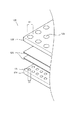
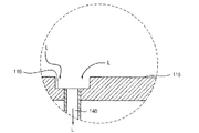
図1は、本発明の一実施例による気液分離装置を一部分解して概略的に示した図であり、図2は、図1に示した気液分離装置を結合して上下方向に切断した断面を示した図である。 FIG. 1 is a schematic exploded view of a gas-liquid separator according to an embodiment of the present invention, and FIG. 2 is a vertical sectional view of the gas-liquid separator shown in FIG. FIG.
図1及び図2を参照すると、本発明の一実施例による気液分離装置100は、分離箱110、フィルター部120、排気管130、及び排水管140を含む。
前記分離箱110は、上部に液体成分(L)と機体成分(G)との混合された気液(GL)が流入される流入口111が形成される。前記流入口111には、外部から前記気液(GL)が実質的に流入される流入管150が連結される。前記流入管150には、外部から前記分離箱110を通じて真空圧が提供される。
Referring to FIGS. 1 and 2, the gas-
The
前記フィルター部120は、前記分離箱110の内部で前記流入口111と隣接するように下部に配置される。前記フィルター部120には、前記気液(GL)が前記流入口111から流入される方向のまま流入され、前記気液(GL)のうち、前記液体成分(L)をフィルタリングする。
The
具体的に、前記気液(GL)は、前記フィルター部120を通過しながら前記機体成分(G)は、前記フィルター部120をそのまま通過して前記フィルター部120と隣接した下部に浮遊するようになり、前記液体成分(L)は、フィルタリングされて前記分離箱110の下部の底面115に落ちるようになる。これは、前記液体成分(L)が前記機体成分(G)に比べて相対的に非常に大きい密度を有しているためである。
Specifically, the gas component (G) passes through the
前記フィルター部120は、第1多孔板122及び第2多孔板124を含む。前記第1多孔板122は、前記分離箱110の内部に隔壁構造に配置される。また、前記第2多孔板124は、前記分離箱110の内部で前記第1多孔板122の下部に隔壁構造に配置される。即ち、前記流入口111から流入された前記気液(GL)は、必ず前記第1多孔板122及び第2多孔板124を通過するようになる。
The
前記第1多孔板122及び第2多孔板124のそれぞれには、前記流入口111から流入された前記気液(GL)をフィルタリングするために第1ホール123と第2ホール125が形成される。これによって、前記気液(GL)は、前記第1多孔板122及び第2多孔板124のうち、前記第1ホール123と前記第2ホール125が形成されない部位にあたり、相対的に密度の高い前記液体成分(L)が前記第1多孔板122及び第2多孔板124のそれぞれから集められ、前記第1ホール123と前記第2ホール125を通じて前記分離箱110の下部の底面115に落ちるようになる。
A
以下、前記フィルター部120については図3を追加的に参照してより詳細に説明する。
図3は、図2に示した気液分離装置のフィルター部を示した図である。
Hereinafter, the
FIG. 3 is a view showing a filter portion of the gas-liquid separator shown in FIG.
図3を追加的に参照すると、前記第1ホール123は、全体面積が前記流入口111の面積に対して約1:1.1より未満の場合には、前記真空圧を急激に低下させて前記流入管150から前記気液(GL)が円滑に流入されないため望ましくなく、約1:1.5を超過する場合には、前記気液(GL)から前記液体成分(L)の集合が円滑に行わないため望ましくない。
Referring to FIG. 3, the
従って、前記第1ホール123は、全体面積が前記流入口111の面積に対して約1:1.1〜1:1.5の比率を有するように形成されることが望ましい。なお、前記第1ホール123はね全体面積が前記流入口111の面積に対して約1:1.1〜1:1.3の比率を有するように形成することが更に望ましい。
Accordingly, the
また、前記第1ホール123は、直径(D1)が前記流入口111の直径に対して約1:0.1より未満の場合には、前記気液(GL)を流れを期待以上に阻止して前記真空圧を急激に低下させるため望ましくなく、約1:0.3を超過する場合には、前記液体成分(L)の集合が円滑でないため望ましくない。
The
従って、前記第1ホール123の直径(D1)は、前記流入口111の直径に対して約1:0.1〜1:0.3の比率を有することが望ましい。一例で、前記流入口111の直径が約200mmの場合、前記第1ホール123の直径(D2)は約30mmであってもよい。
Accordingly, the diameter (D1) of the
これに対し、前記第2ホール125は、前記第1ホール123より相対的に小さい直径(D2)を有する。これは、前記第1ホール123を通過した前記気液(GL)が前記第2ホール125をそのまま通過することを防止して、前記第2多孔板124においても前記液体成分(L)が集合されるようにするためである。
On the other hand, the
具体的に、前記第2ホール125の直径(D2)は、前記第1ホール123の直径(D1)に対して約1:0.7〜1:0.9の比率を有することが望ましい。一例で、前記第2ホール125の直径(D2)は、前記第1ホール123の直径(D1)が約30mmの場合、約25mmであることが可能である。
Specifically, the diameter (D2) of the
これとは違って、前記第1ホール123と前記第2ホール125は交互に構成して前記第1ホール123を通過した前記気液(GL)が前記第2ホール125の直径(D2)に関係なく前記第2多孔板124に前記液体成分(L)が集合されるようにすることができる。
In contrast, the
また、前記第2多孔板124が前記第1多孔板122のように前記分離箱110の内部で隔壁構造からなって同じ面積を有していることにより、前記第2ホール125は、全体面積が前記流入口111の面積に対して前記第1ホール123より狭い約1:1〜1:1.2の比率を有するように形成されることが望ましい。なお、前記第2ホール125は、全体面積が前記流入口111の面積とほぼ同一に形成されることが更に望ましい。
In addition, since the second
一方、前記フィルター部120は、前記第1多孔板122及び第2多孔板124の間に繊維糸からなる少なくとも一枚のフィルターシート126を更に含む。前記フィルターシート126は、通常に不織布に類似な構造であって、繊維糸の交差によって、内部に微細な気孔が複数形成される。ここで、前記フィルターシート126は、一例で、PP(polypropylene)糸からなることが可能である。
Meanwhile, the
前記フィルターシート126は、一般的に一枚ではそれの効果を得にくいため、複数枚が用いられる。例えば、前記フィルターシート126は、約8〜12枚を積み重ねて用いることができる。このような前記フィルターシート126は、それぞれが有する材質の特性上、所定の弾性を有する。即ち、前記フィルターシート126は、前記第1多孔板122及び第2多孔板124の間で加圧された状態で配置される。
A plurality of the
これによって、前記フィルターシート126は、微細な気孔を通じて前記気液(GL)から相対的に密度の高い前記液体成分(L)を集合して、前記分離箱110の下部の底面115に落とすか、或いは前記液体成分(L)をそのまま集めておいて通過できないようにする。
Accordingly, the
このような前記フィルターシート126は、長時間用いる場合、微細な気孔に前記液体成分(L)が飽和状態となってそれの機能を完全に果たすことができないため、交替の必要があるようになる。
When such a
このため、前記分離箱110は、前記第1多孔板122及び第2多孔板124のように前記フィルターシート126の挿入及び分離が可能であるように第1側部117に開口部112が形成される。
For this reason, the
以下、前記フィルターシート126の交替方式について図4及び図5を追加的に参照してより詳細に説明する。
図4は、フィルター部の装着された分離箱を図1のI−I’線に沿って切断した断面図であり、図5は、フィルター部の装着された分離箱を図1のII−II’線に沿って切断した断面図である。
Hereinafter, the replacement method of the
4 is a cross-sectional view taken along the line II ′ of FIG. 1 of the separation box on which the filter unit is mounted. FIG. 5 is a cross-sectional view of the separation box on which the filter unit is mounted. It is sectional drawing cut | disconnected along the line.
図4及び図5を追加的に参照すると、前記分離箱110は、前記開口部112の内側に前記第1多孔板122及び第2多孔板124それぞれの挿入方向に長く形成されて、前記第1多孔板122及び第2多孔板124それぞれの挿入をガイドする第1ガイド溝113及び第2ガイド溝114が形成される。
4 and 5, the
これによって、前記フィルターシート126を交替する場合、まず前記フィルターシート126を加圧している前記第1多孔板122及び第2多孔板124を前記フィルターシート126と一緒に前記第1ガイド溝113及び第2ガイド溝114に沿って前記開口部112を通じて外部に分離させる。
Accordingly, when the
その後、新しい前記フィルターシート126を前記第1多孔板122及び第2多孔板124の間に交替した後、再び前記第1ガイド溝113及び第2ガイド溝114に沿って前記分離箱110の内部に挿入させることによって、交替作業を完了する。
Thereafter, the
この際、前記第1ガイド溝113及び第2ガイド溝114のそれぞれの幅は、挿入の行われる前記第1多孔板122及び第2多孔板124それぞれの厚さよりそれぞれ約1〜3mm広く形成する。
At this time, the widths of the
これは、前記第1多孔板122及び第2多孔板124が前記第1ガイド溝113及び第2ガイド溝114で上下方向に所定流動するようにして前記フィルターシート126をより強く加圧して、前記第1多孔板122及び第2多孔板124を前記分離箱110から分離させる期間、前記第1多孔板122及び第2多孔板124の間から落ちることを最大限に防止するためである。
This is because the first
このように、前記フィルターシート126を交替する場合、これらを加圧している前記第1多孔板122及び第2多孔板124を前記第1ガイド溝113及び第2ガイド溝114に沿って前記分離箱110の内部から分離するか、或いは内部に挿入することによって、交替作業を簡単に行うことができる。即ち、前記フィルターシート126の維持保守の作業を容易に行うことができる。
As described above, when the
この場合、前記気液分離装置100は、前記フィルターシート126のように前記第1多孔板122及び第2多孔板124を前記開口部112を通じて前記分離箱110の内部に挿入させた後、前記開口部112をカバーするためのカバー部160、及び前記分離箱110と前記カバー部160との間に配置され、前記分離箱110の内部を外部からシーリングするためのシーリング部170を更に含むことができる。
In this case, the gas-
ここで、前記カバー部160は、前記開口部112に対応するサイズの板構造からなり、前記シーリング部170を挟んで前記分離箱110にボルト結合されることが可能である。
Here, the
また、前記シーリング部170は、一例で、価格に比べてシーリング効果の優秀なコムリンで構成することができる。これとは違って、前記シーリング部170は、前記気液(GL)の液体成分(L)が強酸性物質を含むなら、耐酸化性がの優秀なシリコン(silicon)またはバイトン(viton)材質のリングからなることが可能である。
In addition, the sealing
前記排気管130は、第1端部132が前記フィルター部120の第2多孔板124と向い合って前記分離箱110の下部を貫いて、前記分離箱110の外部に延長される。前記第1端部132は、別途の遮断部材134を通じて密閉されるように配置することができる。これとは違って、前記排気管130を製作する時、前記第1端部を密閉型端部に製作できることは自明である。
The
前記排気管130は、前記分離箱110の内部で側面に少なくとも一つの排気口136が形成される。前記排気口136には、前記フィルター部120を通過して前記フィルター部120の下部で浮遊している前記気液(GL)の気体成分(G)が流入され、前記排気管130に排気される。
The
この際、前記排気口136は、前記分離箱110の下部の底面115より高く位置する。これは、前記フィルター部120でフィルタリングされて前記底面115に落ちた前記液体成分(L)が前記排気口136に流入されることを防止するためである。
At this time, the
以下、図6を追加的に参照して前記排気口をより詳細に説明する。
図6は、図2に示した気液分離装置の排気管を具体的に示した図である。
図6を追加的に参照すると、前記排気管130は、円周方向に沿って複数の前記排気口136を含む。前記排気口136は、一定の間隔(g)を置いて前記排気管130の側面に配列される。
Hereinafter, the exhaust port will be described in more detail with reference to FIG.
6 is a diagram specifically showing an exhaust pipe of the gas-liquid separation device shown in FIG.
Referring additionally to FIG. 6, the
この際、前記排気口136間の間隔(g)は、前記排気管130の円周に対して、約1:0.07未満の場合には、前記排気口136の間に残っている前記排気管130が非常に薄く形成されて、前記気体成分(G)の排気時、前記排気管130が破損する恐れがあるため望ましくなく、約1:0.1を超過する場合には、前記気体成分(G)の排気と円滑に行わないため望ましくない。
At this time, if the interval (g) between the
よって、前記排気口136の間の間隔(g)は、前記排気管130の全体円周に対して約1:0.07〜1:0.1の比率を有することが望ましい。
前記排気口は、前記排気管の円周面上に形成されるため、前記排気口の間の円周面は、前記排気口の中心線に対して角距離として表現することができる。本実施例の場合、前記排気口の間の間隔は、前記排気管の中心線に対して約30度の角距離を有し、前記排気口の間の残留円周面は中心角が30度である扇形の形状を有する。
Accordingly, it is preferable that the gap (g) between the
Since the exhaust port is formed on the circumferential surface of the exhaust pipe, the circumferential surface between the exhaust ports can be expressed as an angular distance with respect to the center line of the exhaust port. In the present embodiment, the interval between the exhaust ports has an angular distance of about 30 degrees with respect to the center line of the exhaust pipe, and the remaining circumferential surface between the exhaust ports has a center angle of 30 degrees. It has a fan-shaped shape.
前記排水管140は、前記排気管130と隣接した前記分離箱110の下部に連結される。前記排水管140は、前記フィルター部120でフィルタリングされ、前記分離箱110下部の底面115に落ちた前記液体成分(L)を外部に排水させる。
The
この際、前記排水管140は、前記液体成分(L)が前記気体成分(G)に比べて相対的に密度が高いことによって、分離される排出体積が少ないため、前記排気管130よりは相対的に小さい直径を有することができる。
At this time, the
以下、前記排水管140の連結構造について図7及び図8を追加的に参照してより詳細に説明する。
図7は、図2に示した排水管が一実施例によって分離箱に連結された構造を示した図であり、図8は、図2に示した排水管が他の実施例により分離箱に連結された構造を示した図である。
Hereinafter, the connection structure of the
FIG. 7 is a view showing a structure in which the drain pipe shown in FIG. 2 is connected to the separation box according to one embodiment, and FIG. 8 is a diagram showing the drain pipe shown in FIG. It is the figure which showed the structure connected.
図7を参照すると、前記分離箱110は、下部の底面115に周囲より低く形成された段差部116を含む。
前記排水管140は、前記段差部116に連結される。これによって、前記フィルター部120からフィルタリングされて前記底面115に落ちた前記液体成分(L)は、周囲より低く形成された前記段差部116に誘導され、前記排水管140を通じて外部に排水される。
Referring to FIG. 7, the
The
これと相違の実施例として、図8を参照すると、前記分離箱110下部の底面115は、前記分離箱110の中心部から周辺部118に向かって傾くように配置され、前記排水管140は前記底面115の周辺部118を貫くように前記分離箱1100と連結される。 これによって、前記底面115上に落ちた液体成分(L)は、前記傾斜によって、前記周辺部118に集まって前記排水管140を通じて排出される。
As an embodiment different from this, referring to FIG. 8, the
ここで、前記周辺部118は、設計上、前記開口部112と離隔されて配置されることが望ましいが、場合により前記開口部112と隣接するように配置できることは自明である。この際、前記底面115の傾斜角度(a)は、一例で、前記分離箱110のサイズをほぼそのまま維持する範囲で前記液体成分(L)を前記第2側部118に円滑に誘導するために約3〜5度を有することができる。
Here, it is desirable that the
よって、前記フィルター部120の前記第1多孔板122及び第2多孔板124と前記フィルターシート126の上下配置を通じて前記気液(GL)の流れを下部方向にほぼ維持させなら前記気液(GL)から前記液体成分(L)を分離させた後、前記排気管130の側面に形成された前記排気口136を通じて前記気液(GL)の気体成分(G)を排気させることによって、前記分離箱110のサイズが大きくなることを防止することができる。
Therefore, if the flow of the gas-liquid (GL) is substantially maintained in the lower direction through the vertical arrangement of the first
即ち、前記気液分離装置100の設置空間を最小化することによって、周囲の他の装置の設置を容易に行うことができる。
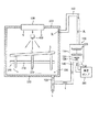
図9は、本発明の一実施例による基板処理装置を概略的に示した構成図である。
That is, by minimizing the installation space of the gas-
FIG. 9 is a block diagram schematically showing a substrate processing apparatus according to an embodiment of the present invention.
図9を参照すると、本発明の一実施例による基板処理装置1000は、工程チャンバー200、基板移送部300、処理液噴射部400、ガス噴射部500、及び気液分離部100を含む。
Referring to FIG. 9, the substrate processing apparatus 1000 according to an embodiment of the present invention includes a
本実施例で、気液分離部は、図1〜図8に示した気液分離装置と同一の構成を有するため、同一の参照番号を付与し、それの重複する詳細な説明は省略する。
前記工程チャンバー200は、内部に搬入される基板(S)を処理するための空間を提供する。ここで、前記基板(S)は、一例で、液晶を用いて画像を表示する液晶表示装置(LCD)を製造するのに用いられるガラス材質の薄膜トランジスター(Thin Film Transistor;TFT)基板またはカラーフィルター(Color Filter;CF)基板であってもよい。これとは違って、前記基板(S)は、半導体素子を製造するのに用いられる半導体基板であってもよい。
In the present embodiment, the gas-liquid separator has the same configuration as the gas-liquid separator shown in FIGS. 1 to 8, and therefore, the same reference numerals are given and detailed description thereof is omitted.
The
前記基板移送部300は、前記工程チャンバー200の内部に搬入される前記基板(S)の下部に配置され、前記基板(S)を移送する。 前記基板移送部300は、前記基板(S)の移送方向と垂直な方向に長く配置されたシャフト310、及び前記シャフト310に一定の間隔に結合されて前記基板(S)を支持するローラー320を含む。
The substrate transfer unit 300 is disposed under the substrate (S) carried into the
前記処理液噴射部400は、前記工程チャンバー200の内部で前記基板(S)の上部に配置される。前記処理液噴射部400は、外部から処理液(L)の供給を受けて前記基板(S)に噴射することによって、前記基板(S)を処理する。
The processing
ここで、前記処理液(L)は、前記基板(S)を対象に前記エッチング工程または前記洗浄工程を行う場合、硫酸(H2SO4)、塩酸(HCl)、フッ酸(HF)、過酸化水素溶液(H2O2)、脱イオン数(H2O)等を含むことができる。 Here, when the etching process or the cleaning process is performed on the substrate (S), the processing liquid (L) is sulfuric acid (H 2 SO 4 ), hydrochloric acid (HCl), hydrofluoric acid (HF), excess Hydrogen oxide solution (H 2 O 2 ), deionization number (H 2 O), and the like can be included.
一方、前記基板移送部300は、前記基板(S)に噴射された前記処理液(L)がいずれか一方に自然に流れるようにして前記エッチング工程または前記洗浄工程をより効率的に進行されるようにするために、前記基板(S)を若干傾斜した状態で移送することができる。 Meanwhile, the substrate transfer unit 300 allows the processing liquid (L) sprayed onto the substrate (S) to flow naturally to either one of the etching process or the cleaning process more efficiently. Therefore, the substrate (S) can be transferred in a slightly inclined state.
ここで、前記基板(S)の傾斜角度は、一例で、約3〜6度でることが可能である。
前記ガス噴射部500は、前記処理液噴射部400の上部に配置される。前記ガス噴射部500は、前記工程チャンバー200の内部に全体的にガス(G)を噴射する。これによって、前記ガス噴射部500は、前記工程チャンバー200の上部の天井210に直接設置することができる。
Here, the inclination angle of the substrate (S) is, for example, about 3 to 6 degrees.
The
このような前記ガス噴射部500は、前記処理液噴射部400の上部から下部方向にガスを噴射することによって、前記処理液噴射部400から噴射される前記処理液(L)が前記基板(S)に向かうように誘導することができる。
The
これによって、前記工程チャンバー200の内部には、前記処理液(L)と前記ガス(G)との混合された気液(GL)が浮遊状態で存在することになる。このような前記気液(GL)は、前記基板移送部300を通じて移送する他の前記基板(S)を汚染させるおそれがある。
As a result, the gas-liquid (GL) in which the processing liquid (L) and the gas (G) are mixed exists in the
前記気液分離部100は、前記工程チャンバー200と隣接した位置で前記工程チャンバー200と流入管150を通じて連結され、前記流入管150を通じて流入される前記気液(GL)から前記処理液(L)及び前記ガス(G)を分離させる。
The gas-
前記流入管150は、前記気液(GL)が前記工程チャンバー200の内部で浮遊状態であるため、前記工程チャンバー200の上部に連結される。具体的に、前記流入管150は、前記工程チャンバー200の天井210または側壁230の上部に連結することができる。ここで、前記流入管150は、前記基板処理装置1000の設置を容易にするようにために前記側壁230の上部に連結されることが一般的である。
The
前記気液分離部100は、上部に前記流入管150が連結されて前記気液(GL)の流入される分離箱110、前記分離箱110の内部で前記流入管150と隣接した下部に配置され、前記気液(GL)から液体成分の前記処理液(L)をフィルタリングするフィルター部120、閉められた上部132が前記フィルター部120と向き合うように前記分離箱110の下部に連結されて前記気液(GL)のうち、前記フィルター部120を通過した気体成分である前記ガス(G)を排気させる排気管130、及び前記排気管130と隣接した前記分離箱110の下部に連結され、前記フィルター部120でフィルタリングされた前記処理液(L)を排水させる第1排水管140を含む。
The gas-
ここで、前記排気管130は、閉められた上部132が別途の遮断部材134により遮断され、側面に前記ガス(G)の排気のために少なくとも一つの排気口136が形成される。
Here, the closed
これによって、前記基板処理装置1000は、前記流入管150から前記気液(GL)が円滑に流入するようにするために排気管130の前記分離箱110と反対側に連結された真空ポンプ600を更に含む。
Accordingly, the substrate processing apparatus 1000 includes a
即ち、前記真空ポンプ600は、真空圧を発生して前記排気管130及び前記分離箱110を通じて前記流入管150に提供する。この際、前記分離箱110の内部に配置された前記フィルター部120は、前記真空圧が基準以下に低下しないように前記図1〜図8に示したように構成することができる。
That is, the
このように、前記工程チャンバー200と前記真空ポンプ600との間に前記気液(GL)から液体成分の前記処理液(L)を分離できる前記気液分離部100を配置させることによって、前記気液(GL)のうち、前記処理液(L)によって前記真空ポンプ600が破損することを防止することができる。
As described above, the gas-
一方、前記基板処理装置1000は、前記工程チャンバー200の下部底面220に連結された第2排水管700を更に含む。前記第2排水管700は、前記基板(S)を処理して前記工程チャンバー200の下部に誘導される前記処理液(L)を外部に排水させる。
Meanwhile, the substrate processing apparatus 1000 further includes a
これによって、前記第1排水管140は、前記第2排水管700に連結され、前記気液分離部100から分離した前記処理液(L)を前記第2排水管700に排水することができる。これで、前記第2排水管700では、前記工程チャンバー200の内部で前記基板(S)を処理するために噴射された前記処理液(L)がすべて排水されることが可能である。
Accordingly, the
このように前記第2排水管700を通じて排水される前記処理液(L)は、場合により別途の回収装置(図示せず)に集まった後、前記処理液噴射部400に再び供給されることによって、リサイクルすることもできる。
Thus, the processing liquid (L) drained through the
よって、前記気液分離部100を通じて前記気液(GL)から前記処理液(L)を分離することによって、前記処理液(L)をより効率的に活用することができる。
以上、添付図面を参照しながら本発明の好適な実施形態について詳細に説明したが、本発明はかかる例に限定されない。本発明の属する技術の分野における通常の知識を有する者であれば、特徴請求の範囲に記載された技術的思想の範疇内において、各種の変更例または修正例に想到し得ることは明らかであり、これらについても、当然に本発明の技術的範囲に属するものと了解される。
Therefore, by separating the processing liquid (L) from the gas-liquid (GL) through the gas-
The preferred embodiments of the present invention have been described in detail above with reference to the accompanying drawings, but the present invention is not limited to such examples. It is obvious that a person having ordinary knowledge in the technical field to which the present invention pertains can make various changes or modifications within the scope of the technical idea described in the claims. Of course, it is understood that these also belong to the technical scope of the present invention.
前述した本発明は、工程チャンバーから気液を真空ポンプを利用して排出させる時、前記気液から液体成分の処理液をフィルタリングすることによって、前記真空ポンプの破損を防止しうる装置に用いることができる。 The present invention described above is used for an apparatus capable of preventing breakage of the vacuum pump by filtering the liquid component treatment liquid from the gas liquid when the gas liquid is discharged from the process chamber using a vacuum pump. Can do.
G…気体成分、ガス、L…液体成分、処理液、GL…気液、S…基板、100…気液分離装置、110…分離箱、111…流入口、112…開口部、113…第1ガイド溝、114…第2ガイド溝、120…フィルター部、122…第1多孔板、124…第2多孔板、126…フィルターシート、130…排気管、132…閉められた上部、134…遮断部材、136…排気口、140…排水管、150…流入管、200…工程チャンバー、300…基板移送部、400…処理液噴射部、500…ガス噴射部、600…真空ポンプ、1000…基板処理装置。
G ... Gas component, gas, L ... Liquid component, treatment liquid, GL ... Gas / liquid, S ... Substrate, 100 ... Gas-liquid separator, 110 ... Separation box, 111 ... Inlet, 112 ... Opening, 113 ... First Guide groove, 114 ... second guide groove, 120 ... filter part, 122 ... first porous plate, 124 ... second porous plate, 126 ... filter sheet, 130 ... exhaust pipe, 132 ... closed upper part, 134 ... blocking member DESCRIPTION OF
Claims (16)
前記分離箱の内部で前記流入口の下部に配置され、前記流入された気液から液体成分をフィルタリングするフィルター部と、
閉められた上部が前記フィルター部と向い合って前記分離箱の下部に連結され、側面に前記フィルター部を通過した前記気液の気体成分を排気させるための少なくとも一つの排気口が形成された排気管と、
前記分離箱の下部に連結され、前記フィルター部でフィルタリングされた前記気液の液体成分を排水させる排水管と、を含むことを特徴とする気液分離装置。 A separation box formed with an inflow port through which gas and liquid are introduced;
A filter unit that is disposed in the lower part of the inlet in the separation box and filters liquid components from the inflowed gas-liquid;
An exhaust in which at least one exhaust port for exhausting a gas component of the gas-liquid that has passed through the filter part is formed on a side surface, the closed upper part facing the filter part and connected to the lower part of the separation box Tube,
A gas-liquid separation device, comprising: a drain pipe connected to a lower portion of the separation box and draining a liquid component of the gas-liquid filtered by the filter unit.
前記分離箱の内部に隔壁構造に配置され、第1ホールの形成された第1多孔板と、
前記分離箱の内部で前記第1多孔板の下部に隔壁構造に配置され、前記第1ホールより小さい直径を有する第2ホールの形成された第2多孔板と、を含むことを特徴とする請求項1に記載の気液分離装置。 The filter section is
A first perforated plate disposed in a partition structure inside the separation box and having a first hole;
And a second perforated plate disposed in a partition structure below the first perforated plate inside the separation box and having a second hole having a smaller diameter than the first hole. Item 2. The gas-liquid separator according to Item 1.
前記開口部をカバーするカバー部と、
前記カバー部と前記分離箱との間をシーリングするシーリング部と、を更に含むことを特徴とする請求項6に記載の気液分離装置。 The separation box is formed with an opening on one side so that the first and second perforated plates and the filter sheet can be inserted and separated.
A cover portion covering the opening;
The gas-liquid separation device according to claim 6, further comprising a sealing portion that seals between the cover portion and the separation box.
前記工程チャンバーの内部で前記基板の上部に配置され、外部から供給される処理液を前記基板に噴射する処理液噴射部と、
前記処理液噴射部の上部に配置され、前記工程チャンバーに全体的にガスを噴射するガス噴射部と、
前記工程チャンバーと流入管を通じて連結され、前記工程チャンバーの内部から前記処理液と前記ガスとの混合された気液が流入され、前記流入された気液から前記処理液と前記ガスとを分離させる気液分離部と、を含み、
前記気液分離部は、
上部に前記流入管が連結され、前記気液の流入される分離箱と、
前記分離箱の内部で前記流入管の下部に配置され、前記流入された気液から前記処理液をフィルタリングするフィルター部と、
閉められた上部が前記フィルター部と向い合って前記分離箱の下部に連結され、側面に前記気液のうち、前記フィルター部を通過した前記ガスを排気させるための少なくとも一つの排気口が形成された排気管と、
前記排気管と隣接した前記分離箱の下部に連結され、前記フィルター部でフィルタリングされた前記気液の液体成分を排水させる第1排水管と、を含むことを特徴とする基板処理装置。 A process chamber providing a space for processing a substrate;
A processing liquid ejecting unit disposed on the substrate inside the process chamber and ejecting a processing liquid supplied from the outside onto the substrate;
A gas injection unit that is disposed above the processing liquid injection unit and injects gas entirely into the process chamber;
The process liquid is connected to the process chamber through an inflow pipe, and a gas / liquid mixture of the process liquid and the gas is introduced from the inside of the process chamber, and the process liquid and the gas are separated from the gas / liquid introduced. A gas-liquid separator, and
The gas-liquid separator is
A separation box into which the inflow pipe is connected, and the gas-liquid is introduced;
A filter unit that is disposed in the lower part of the inflow pipe inside the separation box and filters the processing liquid from the inflowed gas and liquid;
The closed upper part faces the filter part and is connected to the lower part of the separation box, and at least one exhaust port for exhausting the gas that has passed through the filter part is formed on the side surface. Exhaust pipe,
A substrate processing apparatus, comprising: a first drain pipe connected to a lower portion of the separation box adjacent to the exhaust pipe and draining a liquid component of the gas-liquid filtered by the filter unit.
Applications Claiming Priority (2)
| Application Number | Priority Date | Filing Date | Title |
|---|---|---|---|
| KR1020080089171A KR101000296B1 (en) | 2008-09-10 | 2008-09-10 | Apparatus for separating a gas-liquid and apparatus for processing a substrate including the same |
| KR10-2008-0089171 | 2008-09-10 |
Publications (2)
| Publication Number | Publication Date |
|---|---|
| JP2010064068A true JP2010064068A (en) | 2010-03-25 |
| JP4870801B2 JP4870801B2 (en) | 2012-02-08 |
Family
ID=42017761
Family Applications (1)
| Application Number | Title | Priority Date | Filing Date |
|---|---|---|---|
| JP2009208934A Active JP4870801B2 (en) | 2008-09-10 | 2009-09-10 | Gas-liquid separator and substrate processing apparatus including the same |
Country Status (4)
| Country | Link |
|---|---|
| JP (1) | JP4870801B2 (en) |
| KR (1) | KR101000296B1 (en) |
| CN (1) | CN101670215A (en) |
| TW (1) | TWI367776B (en) |
Cited By (4)
| Publication number | Priority date | Publication date | Assignee | Title |
|---|---|---|---|---|
| CN107202006A (en) * | 2016-03-16 | 2017-09-26 | 细美事有限公司 | Pump and liquid supplying apparatus |
| CN108786283A (en) * | 2018-08-31 | 2018-11-13 | 中冶北方(大连)工程技术有限公司 | A kind of ore dressing dewatering operation three-level Separate System of Water-jet |
| KR20210144425A (en) * | 2020-05-22 | 2021-11-30 | 김현철 | Vacuum Suction Device for Cell Smear |
| KR102613617B1 (en) * | 2023-02-13 | 2023-12-14 | 주식회사 어반트리 | sustainable antimicrobial dust collector |
Families Citing this family (8)
| Publication number | Priority date | Publication date | Assignee | Title |
|---|---|---|---|---|
| TWI440607B (en) * | 2011-12-13 | 2014-06-11 | Vacuum Elimination Device and Method | |
| CN102720549B (en) * | 2012-06-20 | 2015-04-08 | 河北省电力勘测设计研究院 | Vacuum energy vortex steam condenser |
| RU2529672C1 (en) * | 2013-07-09 | 2014-09-27 | Шлюмберже Текнолоджи Б.В. | Multi-phase separator-grinder |
| CN104174188B (en) * | 2014-08-08 | 2015-09-30 | 西北工业大学 | A kind of water hole depassing unit |
| KR102221258B1 (en) * | 2018-09-27 | 2021-03-02 | 세메스 주식회사 | Apparatus for Dispensing Chemical |
| KR102168831B1 (en) * | 2018-12-10 | 2020-10-22 | 주식회사 포스코 | Filtering apparatus for automatically discharging waste liguid |
| CN110685892B (en) * | 2019-10-31 | 2021-09-03 | 福雪莱冷暖设备(东莞)有限公司 | Diaphragm vacuum pump |
| CN111569560B (en) * | 2020-05-26 | 2021-06-25 | 江苏双旭动力科技有限公司 | Expansion energy-releasing steam-water separator |
Citations (7)
| Publication number | Priority date | Publication date | Assignee | Title |
|---|---|---|---|---|
| JPS61106324A (en) * | 1984-10-25 | 1986-05-24 | Advantest Corp | Ic handling unit |
| JPS61197206A (en) * | 1985-02-27 | 1986-09-01 | Toyoda Gosei Co Ltd | Preparation device for rubber material |
| JPH02120675A (en) * | 1988-10-31 | 1990-05-08 | Nippon Telegr & Teleph Corp <Ntt> | Method for measuring electric signal |
| JPH07202397A (en) * | 1993-12-28 | 1995-08-04 | Nippon Dennetsu Keiki Kk | Flux mist collector |
| JPH11137938A (en) * | 1997-11-07 | 1999-05-25 | Kyushu Electric Power Co Inc | Performance deterioration preventing device for gas turbine |
| JP2004016842A (en) * | 2002-06-12 | 2004-01-22 | Tsudakoma Corp | Mist recovering apparatus |
| WO2008036849A2 (en) * | 2006-09-22 | 2008-03-27 | Applied Materials, Inc. | Particle trap / filter for recirculating a dilution gas in a plasma enhanced chemical vapor deposition system |
-
2008
- 2008-09-10 KR KR1020080089171A patent/KR101000296B1/en active IP Right Grant
-
2009
- 2009-09-08 TW TW098130290A patent/TWI367776B/en active
- 2009-09-09 CN CN200910170848A patent/CN101670215A/en active Pending
- 2009-09-10 JP JP2009208934A patent/JP4870801B2/en active Active
Patent Citations (7)
| Publication number | Priority date | Publication date | Assignee | Title |
|---|---|---|---|---|
| JPS61106324A (en) * | 1984-10-25 | 1986-05-24 | Advantest Corp | Ic handling unit |
| JPS61197206A (en) * | 1985-02-27 | 1986-09-01 | Toyoda Gosei Co Ltd | Preparation device for rubber material |
| JPH02120675A (en) * | 1988-10-31 | 1990-05-08 | Nippon Telegr & Teleph Corp <Ntt> | Method for measuring electric signal |
| JPH07202397A (en) * | 1993-12-28 | 1995-08-04 | Nippon Dennetsu Keiki Kk | Flux mist collector |
| JPH11137938A (en) * | 1997-11-07 | 1999-05-25 | Kyushu Electric Power Co Inc | Performance deterioration preventing device for gas turbine |
| JP2004016842A (en) * | 2002-06-12 | 2004-01-22 | Tsudakoma Corp | Mist recovering apparatus |
| WO2008036849A2 (en) * | 2006-09-22 | 2008-03-27 | Applied Materials, Inc. | Particle trap / filter for recirculating a dilution gas in a plasma enhanced chemical vapor deposition system |
Cited By (6)
| Publication number | Priority date | Publication date | Assignee | Title |
|---|---|---|---|---|
| CN107202006A (en) * | 2016-03-16 | 2017-09-26 | 细美事有限公司 | Pump and liquid supplying apparatus |
| CN108786283A (en) * | 2018-08-31 | 2018-11-13 | 中冶北方(大连)工程技术有限公司 | A kind of ore dressing dewatering operation three-level Separate System of Water-jet |
| CN108786283B (en) * | 2018-08-31 | 2023-10-10 | 中冶北方(大连)工程技术有限公司 | Three-stage gas-liquid separation system for mineral separation and dehydration operation |
| KR20210144425A (en) * | 2020-05-22 | 2021-11-30 | 김현철 | Vacuum Suction Device for Cell Smear |
| KR102375491B1 (en) * | 2020-05-22 | 2022-03-17 | 주식회사 티에스티이 | Vacuum Suction Device for Cell Smear |
| KR102613617B1 (en) * | 2023-02-13 | 2023-12-14 | 주식회사 어반트리 | sustainable antimicrobial dust collector |
Also Published As
| Publication number | Publication date |
|---|---|
| KR101000296B1 (en) | 2010-12-13 |
| CN101670215A (en) | 2010-03-17 |
| TWI367776B (en) | 2012-07-11 |
| JP4870801B2 (en) | 2012-02-08 |
| KR20100030288A (en) | 2010-03-18 |
| TW201016293A (en) | 2010-05-01 |
Similar Documents
| Publication | Publication Date | Title |
|---|---|---|
| JP4870801B2 (en) | Gas-liquid separator and substrate processing apparatus including the same | |
| KR101688620B1 (en) | Wafer storage container | |
| JP2008072096A (en) | Buffer tank, intermediate accumulation apparatus, liquid treatment apparatus, and supplying method of treating liquid | |
| JP2015099919A (en) | Substrate cleaning device | |
| KR101125568B1 (en) | Etching apparatus | |
| CN106186710A (en) | For the etch system of glass substrate and use the engraving method of described system | |
| KR20160138119A (en) | Etching apparatus, etching method, substrate manufacturing method, and substrate | |
| KR100756522B1 (en) | Air-knife apparatus to dry glass | |
| KR102323077B1 (en) | Head cleaning unit and substrate treating apparatus including the same | |
| JP2010181504A (en) | Liquid-suctioning tank and droplet discharge device provided with the same | |
| KR102396243B1 (en) | Display panel floating stage having washing means and washing method thereof | |
| JP2006026634A (en) | Inhalation unit assembly | |
| KR20090047115A (en) | Cleaning device and method of cleaning substrate | |
| KR101099576B1 (en) | System for supplying and collecting cleaning solution | |
| TWI568500B (en) | Apparatuses for jetting fluid | |
| KR20140134378A (en) | Apparatus for jetting fluid and apparatus for cleaning a substrate having the same | |
| KR101922684B1 (en) | Apparatus for treating substrate | |
| KR20080023293A (en) | Wet treatment apparatus and process for producing display panel | |
| KR100930826B1 (en) | Single Sheet Washing Equipment | |
| KR100956557B1 (en) | Apparatus of supplying chemical liquid | |
| KR100699011B1 (en) | Circuit ething nozzle | |
| KR101099589B1 (en) | Liquid knife for supplying a processing liquid onto a substrate | |
| KR101398441B1 (en) | Single type cleaning apparatus for substrate | |
| KR101451857B1 (en) | Chemical supply apparatus | |
| KR101922692B1 (en) | Wafer storage container |
Legal Events
| Date | Code | Title | Description |
|---|---|---|---|
| A977 | Report on retrieval |
Free format text: JAPANESE INTERMEDIATE CODE: A971007 Effective date: 20110307 |
|
| A131 | Notification of reasons for refusal |
Free format text: JAPANESE INTERMEDIATE CODE: A131 Effective date: 20110419 |
|
| A521 | Request for written amendment filed |
Free format text: JAPANESE INTERMEDIATE CODE: A523 Effective date: 20110719 |
|
| TRDD | Decision of grant or rejection written | ||
| A01 | Written decision to grant a patent or to grant a registration (utility model) |
Free format text: JAPANESE INTERMEDIATE CODE: A01 Effective date: 20111025 |
|
| A01 | Written decision to grant a patent or to grant a registration (utility model) |
Free format text: JAPANESE INTERMEDIATE CODE: A01 |
|
| A61 | First payment of annual fees (during grant procedure) |
Free format text: JAPANESE INTERMEDIATE CODE: A61 Effective date: 20111117 |
|
| R150 | Certificate of patent or registration of utility model |
Ref document number: 4870801 Country of ref document: JP Free format text: JAPANESE INTERMEDIATE CODE: R150 Free format text: JAPANESE INTERMEDIATE CODE: R150 |
|
| FPAY | Renewal fee payment (event date is renewal date of database) |
Free format text: PAYMENT UNTIL: 20141125 Year of fee payment: 3 |
|
| R250 | Receipt of annual fees |
Free format text: JAPANESE INTERMEDIATE CODE: R250 |
|
| R250 | Receipt of annual fees |
Free format text: JAPANESE INTERMEDIATE CODE: R250 |
|
| R250 | Receipt of annual fees |
Free format text: JAPANESE INTERMEDIATE CODE: R250 |
|
| R250 | Receipt of annual fees |
Free format text: JAPANESE INTERMEDIATE CODE: R250 |
|
| R250 | Receipt of annual fees |
Free format text: JAPANESE INTERMEDIATE CODE: R250 |
|
| R250 | Receipt of annual fees |
Free format text: JAPANESE INTERMEDIATE CODE: R250 |
|
| R250 | Receipt of annual fees |
Free format text: JAPANESE INTERMEDIATE CODE: R250 |
|
| R250 | Receipt of annual fees |
Free format text: JAPANESE INTERMEDIATE CODE: R250 |
|
| R250 | Receipt of annual fees |
Free format text: JAPANESE INTERMEDIATE CODE: R250 |
|
| R250 | Receipt of annual fees |
Free format text: JAPANESE INTERMEDIATE CODE: R250 |