JP2010059624A - Hollow metal joint for square steel tube, method of manufacturing hollow metal joint, and square steel tube member using the same - Google Patents
Hollow metal joint for square steel tube, method of manufacturing hollow metal joint, and square steel tube member using the same Download PDFInfo
- Publication number
- JP2010059624A JP2010059624A JP2008224121A JP2008224121A JP2010059624A JP 2010059624 A JP2010059624 A JP 2010059624A JP 2008224121 A JP2008224121 A JP 2008224121A JP 2008224121 A JP2008224121 A JP 2008224121A JP 2010059624 A JP2010059624 A JP 2010059624A
- Authority
- JP
- Japan
- Prior art keywords
- steel pipe
- square steel
- joint
- metal hollow
- hollow joint
- Prior art date
- Legal status (The legal status is an assumption and is not a legal conclusion. Google has not performed a legal analysis and makes no representation as to the accuracy of the status listed.)
- Granted
Links
Images


Landscapes
- Joining Of Building Structures In Genera (AREA)
- Rod-Shaped Construction Members (AREA)
- Shaping Metal By Deep-Drawing, Or The Like (AREA)
Abstract
Description
本発明は、角形鋼管の端部と他の構造部材とを接合可能とする角形鋼管用金属製中空ジョイント、この金属製中空ジョイントの製造方法、及びこれを用いた角形鋼管部材とに関するものである。 The present invention relates to a metal hollow joint for a square steel pipe capable of joining an end of a square steel pipe and another structural member, a method for manufacturing the metal hollow joint, and a square steel pipe member using the metal hollow joint. .
従来より、柱、梁、ブレースからなる鉄骨構造の建築構造物や、乗用車の車体、建設機械のキャビン等の機械構造物においては、これらを構成する構造部材として角形鋼管が広く用いられている。そして、従来から、この角形鋼管の端部に他の部材を取り付ける、又は様々な加工を施すことにより、角形鋼管の端部を他の構造部材に接合可能に構成された様々な角形鋼管部材が提案されている。 2. Description of the Related Art Conventionally, square steel pipes are widely used as structural members constituting steel structures such as columns, beams, and braces, and machine structures such as passenger car bodies and construction machine cabins. And conventionally, various square steel pipe members constituted so that the end of the square steel pipe can be joined to other structural members by attaching other members to the end of the square steel pipe or performing various processes. Proposed.
例えば、建築分野においては、下記のような角形鋼管部材が提案されている。 For example, in the construction field, the following square steel pipe members have been proposed.
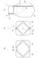
図21(a)は、従来から提案されている角形鋼管部材110を他の構造部材103に接合した接合構造100を示す斜視図であり、図21(b)は、その分解斜視図であり、図21(c)はその平面断面図である。この角形鋼管部材110は、角形鋼管101の両端に対して、角形鋼管101の断面形状に対応した形状からなる正方形状の接合プレート105と、L字状の一対のアングル部材107と、複数のボルト孔109aが形成されたエンドプレート109とが溶接により順に固着されて構成されている。この角形鋼管部材110は、エンドプレート109をH形鋼からなる構造部材103に対してボルト接合することにより、構造部材103に対して接合されている。
FIG. 21 (a) is a perspective view showing a
ここで、一対のアングル部材107は、平面視において十字形とされるように配置されている。これによって、接合プレート105とエンドプレート109との間には、ソケットレンチやインパクトレンチ等の締結工具の一部を配置可能な締結作業用空間111が形成されることになる。これにより、角形鋼管101や構造部材103の大きさに対してエンドプレート105の大きさを大きくできない場合でも、ボルトナットの締結作業を行う締結作業用空間111の確保が可能となっている。
Here, the pair of
また、この他にも、例えば、特許文献1に開示のように、角形鋼管からなる柱の端部を、スウェージング加工により小径に絞り込み、これを断面円形とすることにより、柱の端部の外側にボルトナットの締結作業を行う締結作業用空間を形成させた角形鋼管部材が提案されている。
In addition to this, for example, as disclosed in
また、特許文献2においては、角形鋼管からなる柱の端部を、断面略十字状等の所定形状となるようにプレス加工により圧潰し、柱の端部の外側にボルトナットの締結作業用空間を形成させた角形鋼管部材が提案されている。
Moreover, in
また、機械分野においては、例えば、特許文献3に示すような、断面角形に形成されたサイドメンバとバンパーとを接合する接合構造が開示されている。この接合構造においては、開口されたサイドメンバの前端部にバンパーブラケットが固着され、このバンパーブラケットをバンパーに対してボルト接合することにより、サイドメンバとバンパーとを接合している。
Further, in the mechanical field, for example, as shown in
しかしながら、図21に示される角形鋼管部材110は角形鋼管101と一対のアングル部材107との間で断面が不連続になるため、接合プレート105を介してはいても応力集中が発生し、角形鋼管の性能を十分に発揮できない。また、一対のアングル部材107の全周を溶接するには入り組んだ溶接をする必要があるので手間がかかるとともに、接合プレート105に溶接によるひずみが発生する可能性もあり、仕上がり精度の確保が困難になる。
However, since the cross section of the rectangular
また、特許文献1、2に開示の技術を用いた場合、角形鋼管部材の断面を変化させながら軸方向の長さを調整する必要があり、しかもその端面をエンドプレートに溶接するには平面を出す必要があるため、現実的には端面の仕上げ加工が必要となり、加工に手間がかかる。
In addition, when the techniques disclosed in
また、特許文献3に開示の技術を用いた場合も同様に、サイドメンバの端部からバンパーまでの間隔が合わない場合に、サイドメンバをバンパーに対して正確に接合することができず、車体の組立作業が困難となる場合が考えられる。
Similarly, when the technique disclosed in
また、特許文献1〜3に開示の技術を用いた場合、角形鋼管を部材長さに合わせて精密に加工する必要があるため、外部で加工したものを用いるときは数量管理が必要となり、様々な長さの材料をストックする必要が生じ、保管性の点で優れたものとはいえず、角形鋼管を自社で加工するのであれば、手間がかかり、廃材の発生により環境に負荷が掛かるという問題点がある。
In addition, when the techniques disclosed in
即ち、従来においては、ボルトナットの締結作業用空間を確保しつつ、加工度が低く、寸法精度の確保が容易で、保管性に優れた角形鋼管部材は提案されていなかった。 That is, conventionally, there has not been proposed a square steel pipe member that secures a space for fastening bolts and nuts, has a low degree of processing, easily secures dimensional accuracy, and has excellent storability.
そこで、本発明は、上述した問題点に鑑みて案出されたものであり、その目的とするところは、角形鋼管の端部と他の構造部材とを接合可能とする部材であって、角形鋼管の端部からこの角形鋼管が接合されるべき構造部材までの長さを調整可能とする機能を有し、更に、ボルトナットの締結作業用空間を確保可能しつつ、加工度が低く、寸法精度の確保が容易で、保管性に優れた角形鋼管部材を構成可能とする角形鋼管用金属製中空ジョイント、これの製造方法及びこれを用いた角形鋼管部材を提供することにある。 Therefore, the present invention has been devised in view of the above-described problems, and the object of the present invention is a member that can join an end of a square steel pipe and another structural member. It has the function of adjusting the length from the end of the steel pipe to the structural member to which this square steel pipe is to be joined. An object of the present invention is to provide a metal hollow joint for a square steel pipe that can easily form a square steel pipe member that is easy to ensure accuracy and has excellent storability, a manufacturing method thereof, and a square steel pipe member using the same.
本発明者は、上述した課題を解決するために、鋭意検討の末、下記の発明を案出した。 In order to solve the above-described problems, the present inventors have devised the following invention after intensive studies.
請求項1に係る角形鋼管用金属製中空ジョイントは、筒状のジョイント本体の軸方向一端側に設けられ、角形鋼管内に装入される断面角形状の装入部と、上記ジョイント本体の軸方向他端側に設けられ、その他端側端面に対してボルト孔が複数形成されたエンドプレートが固着されるプレート接合部とを備え、上記プレート接合部は、少なくとも上記ボルト孔の位置に対応した部位において、上記装入部よりもその内側に狭まって形成されていることを特徴とする。
A metal hollow joint for a rectangular steel pipe according to
請求項2に係る角形鋼管用金属製中空ジョイントは、請求項1に係る発明において、上記ジョイント本体は、一体的に成形されてなることを特徴とする。 A metal hollow joint for a square steel pipe according to a second aspect is the invention according to the first aspect, wherein the joint body is integrally formed.
請求項3に係る角形鋼管用金属製中空ジョイントは、請求項1又は2に係る発明において、上記プレート接合部は、上記装入部がなす角形断面の四隅の角部に対応した部位において、当該装入部よりもその内側に狭まって形成されていることを特徴とする。 A metal hollow joint for a rectangular steel pipe according to a third aspect is the invention according to the first or second aspect, wherein the plate joint is a portion corresponding to the four corners of the square cross section formed by the insertion portion. It is characterized in that it is narrower on the inner side than the charging portion.
請求項4に係る角形鋼管用金属製中空ジョイントは、請求項1〜3の何れか1項に係る発明において、上記ジョイント本体の一端側端部において、上記装入部よりもその内側に狭まって形成された案内部を更に備えることを特徴とする。
The metal hollow joint for a square steel pipe according to claim 4 is the invention according to any one of
請求項5に係る角形鋼管用金属製中空ジョイントは、請求項4に係る発明において、上記案内部の外周には、上記ジョイント本体の一端側端部に向かうにつれてその軸心側に徐々に狭まるようなテーパー面が形成されていることを特徴とする。 According to a fifth aspect of the present invention, in the metal hollow joint for a square steel pipe according to the fourth aspect of the invention, the outer periphery of the guide portion is gradually narrowed toward the axial center side toward the one end of the joint body. A tapered surface is formed.
請求項6に係る角形鋼管用金属製中空ジョイントは、請求項1〜5の何れか1項に係る発明において、上記装入部には、ねじ切り加工された貫通孔を有してその内側に向けて突出された筒状突起が形成されていることを特徴とする。 A metal hollow joint for a rectangular steel pipe according to a sixth aspect is the invention according to any one of the first to fifth aspects, wherein the insertion portion has a threaded through hole and faces the inside thereof. A protruding cylindrical protrusion is formed.
請求項7に係る金属製中空ジョイントの製造方法は、請求項1〜7の何れか1項に記載の金属製中空ジョイント二つをその軸方向の一端側端部を突き合わせた形状に成形可能なハイドロフォーム用分割金型内に金属管を配置し、上記金属管に対して、軸押し及び液圧の付与によりハイドロフォーム加工を施し、上記ハイドロフォーム加工された成形品をその軸方向に二分割することを特徴とする。
The method for manufacturing a metal hollow joint according to
請求項8に係る金属製中空ジョイントの製造方法は、請求項1〜6の何れか1項に記載の金属製中空ジョイント二つをその軸方向の一端側端部を突き合わせた形状に成形可能なハイドロフォーム用分割金型内に金属管を配置し、上記金属管に対して、軸押し及び液圧の付与によりハイドロフォーム加工を施し、上記ハイドロフォーム加工後に得られた成形品に、上記分割金型に設けられた穿孔手段によって、穴あけ加工とともにバーリング加工を施し、上記バーリング加工された成形品をその軸方向に二分割し、上記分割された成形品のバーリング加工による貫通孔にねじ切り加工を施すことを特徴とする。
The method for manufacturing a metal hollow joint according to claim 8 can form the two metal hollow joints according to any one of
請求項9に係る金属製中空ジョイントの製造方法は、請求項1〜6の何れか1項に記載の金属製中空ジョイント二つをその軸方向の一端側端部を突き合わせた形状に成形可能なハイドロフォーム用分割金型内に金属管を配置し、上記金属管に対して、軸押し及び液圧の付与によりハイドロフォーム加工を施し、上記ハイドロフォーム加工後に得られた成形品に、上記分割金型に設けられた穿孔手段によって、穴あけ加工とともにバーリング加工を施し、上記バーリング加工による貫通孔にねじ切り加工を施し、上記ねじ切り加工された成形品をその軸方向に二分割することを特徴とする。
The method for manufacturing a metal hollow joint according to
請求項10に係る金属製中空ジョイントの製造方法は、請求項1〜6の何れか1項に記載の金属製中空ジョイント二つをその軸方向の一端側端部を突き合わせた形状に成形可能なハイドロフォーム用分割金型内に金属管を配置し、上記金属管に対して、軸押し及び液圧の付与によりハイドロフォーム加工を施し、上記ハイドロフォーム加工後に得られた成形品に、上記分割金型に設けられた穿孔手段によって、穴あけ加工とともにバーリング加工を施しつつ当該バーリング加工による貫通孔に雌ねじ部材を埋め込み配置し、上記バーリング加工された成形品をその軸方向に二分割することを特徴とする。
The method for manufacturing a metal hollow joint according to
請求項11に係る角形鋼管部材は、請求項1〜6の何れか1項に記載の金属製中空ジョイントの装入部が、上記角形鋼管の端部にその軸方向にスライド可能に装入されるとともに、当該角形鋼管に対して固定されていることを特徴とする。 A rectangular steel pipe member according to an eleventh aspect is configured such that the insertion portion of the metal hollow joint according to any one of the first to sixth aspects is inserted into an end portion of the rectangular steel pipe so as to be slidable in the axial direction. And is fixed to the square steel pipe.
請求項12に係る角形鋼管部材は、請求項11に係る発明において、上記金属製中空ジョイントは、溶接又はボルトにより、上記角形鋼管に対して固定されていることを特徴とする。 The square steel pipe member according to a twelfth aspect of the invention according to the eleventh aspect is characterized in that the metal hollow joint is fixed to the square steel pipe by welding or bolts.
請求項13に係る角形鋼管部材は、請求項11に係る発明において、上記金属製中空ジョイントは鋼製であって、上記角形鋼管の側面に形成された溶接用孔と当該鋼製中空ジョイントとの境界を溶接することによって、上記角形鋼管に対して固定されていることを特徴とする。
The square steel pipe member according to
請求項14に係る角形鋼管部材は、請求項11に係る発明において、上記金属製中空ジョイントは、着脱可能なボルトにより、上記角形鋼管に対して固定されていることを特徴とする。 A square steel pipe member according to a fourteenth aspect is the invention according to the eleventh aspect, wherein the metal hollow joint is fixed to the square steel pipe by a detachable bolt.
請求項15に係る角形鋼管部材は、請求項11に係る発明において、上記金属製中空ジョイントは、当該金属製中空ジョイントの装入部に設けられ、内周面がねじ切り加工された雌ねじ孔と、上記角形鋼管の軸方向に延長されて当該角形鋼管に形成された長孔とを貫通するボルトのボルト接合により、上記角形鋼管に対して固定されていることを特徴とする。 A rectangular steel pipe member according to a fifteenth aspect is the invention according to the eleventh aspect, wherein the metal hollow joint is provided in a loading portion of the metal hollow joint, and an internal thread hole whose inner peripheral surface is threaded, The rectangular steel pipe is fixed to the rectangular steel pipe by bolting of a bolt extending in the axial direction of the rectangular steel pipe and penetrating a long hole formed in the rectangular steel pipe.
請求項1に係る発明によれば、角形鋼管に対してその軸方向にスライド可能に装入されるため、金属製中空ジョイントの角形鋼管の端部からの突出長さを調整することが可能となっており、金属製中空ジョイントが取り付けられた角形鋼管部材の軸方向長さの寸法精度の確保が容易になると共に、仕上げ長さ1つ1つに対して角形鋼管長さを調整する精密加工の必要がなくなるため、注文、あるいはストックする角形鋼管の寸法を集約できるため保管性が高まり、また廃材を減らすことで環境負荷を低減できる。また、角形鋼管と金属性中空ジョイントは同様な中空の角形断面であるため、溶接線の増加や応力集中の影響を抑えることが可能となる。また、請求項1に係る金属製中空ジョイントは、ボルトナットの締結作業用空間を比較的広く得つつも、軸心の外側に広く断面を確保可能な形状とされている。また、角形鋼管の端部にこれとは別部材の金属性中空ジョイントを装入させる構成としていることから、金属製中空ジョイントのみを高強度薄肉化させることができ、これによって金属製中空ジョイントを軽量化させて角形鋼管部材や、角形鋼管部材を有する構造物全体の軽量化を図ることが可能となる。また、本発明における金属製中空ジョイントは、これが取り付けられた角形鋼管部材が、エンドプレート以外に外側に突出した部材がないので、仕上げ材等を取り付ける際の障害とならず、設計の自由度を向上させることが可能となっている。 According to the first aspect of the present invention, since the rectangular steel pipe is slidably inserted in the axial direction, the protruding length of the metal hollow joint from the end of the square steel pipe can be adjusted. It becomes easy to ensure the dimensional accuracy of the axial length of a square steel pipe member to which a metal hollow joint is attached, and the precision machining to adjust the square steel pipe length for each finished length Therefore, it is possible to consolidate the dimensions of the square steel pipes to be ordered or stocked, so that the storability is improved, and the environmental burden can be reduced by reducing waste materials. In addition, since the square steel pipe and the metallic hollow joint have the same hollow square cross section, it is possible to suppress the influence of an increase in weld line and stress concentration. Further, the metal hollow joint according to the first aspect has a shape capable of ensuring a wide cross section outside the shaft center while obtaining a relatively wide space for fastening the bolt and nut. In addition, since the metal hollow joint, which is a separate member, is inserted into the end portion of the square steel pipe, only the metal hollow joint can be thinned with high strength. It is possible to reduce the weight of the square steel pipe member or the entire structure having the square steel pipe member. In addition, the metal hollow joint according to the present invention has no square steel pipe member to which the metal hollow joint is attached, and there is no member projecting outside other than the end plate. It is possible to improve.
請求項2に係る発明によれば、溶接を用いない一体成形により得られているため、溶接歪みによる仕上がり寸法精度、強度への悪影響がなく、また、外観において切断線等がないことから意匠性の観点からも優れている。
According to the invention according to
請求項3に係る発明によれば、プレート接合部の断面二次モーメントを比較的大きく確保しつつも、締結作業用空間を四箇所確保することが可能となる。
According to the invention which concerns on
請求項4に係る発明によれば、案内部により金属製中空ジョイントが角形鋼管に対して案内されることになり、金属製中空ジョイントの装入作業が容易となる。 According to the invention which concerns on Claim 4, a metal hollow joint will be guided with respect to a square steel pipe by a guide part, and the insertion operation | work of a metal hollow joint becomes easy.
請求項5に係る発明によれば、金属製中空ジョイントの装入作業が更に容易なものとなる。
According to the invention which concerns on
請求項6に係る発明によれば、板厚の薄い金属製中空ジョイントでもボルトとの螺合長さを確保可能となる。 According to the invention which concerns on Claim 6, even if it is a metal hollow joint with thin plate | board thickness, it becomes possible to ensure the screwing length with a volt | bolt.
請求項7に係る発明によれば、他の成形方法により製造した場合と比べて、本発明に係る金属製中空ジョイントのような複雑形状のものであっても容易に製造することができる。また、一組の分割金型のキャビティから二つの金属製中空ジョイントを得ることができ、量産性に優れたものとなっている。また、ハイドロフォーム成形の特性上、金属製中空ジョイントの装入部よりもプレート接合部の板厚の方を厚くすることが可能となるため、エンドプレートへの溶接によるひずみを抑えることができる。
According to the
請求項13に係る発明によれば、溶接姿勢、習熟度による品質のばらつきを抑えることが可能となる。
According to the invention which concerns on
請求項14に係る発明によれば、金属製中空ジョイントと角形鋼管とを別管理する必要がなくなり、保管性に優れたものとなる。 According to the invention which concerns on Claim 14, it becomes unnecessary to manage separately a metal hollow joint and a square steel pipe, and it becomes what was excellent in storage property.
請求項15に係る発明によれば、金属製中空ジョイントの突出長さの調整範囲が広がっており、角形鋼管と金属製中空ジョイントとをより確実に固定することが可能となっている。 According to the invention which concerns on Claim 15, the adjustment range of the protrusion length of a metal hollow joint has expanded, and it becomes possible to fix a square steel pipe and a metal hollow joint more reliably.
以下、本発明を実施するための最良の形態として、角形鋼管の端部と他の構造部材とを接合可能とする金属製中空ジョイントについて、図面を参照しながら詳細に説明する。 Hereinafter, as a best mode for carrying out the present invention, a metal hollow joint capable of joining an end of a square steel pipe and another structural member will be described in detail with reference to the drawings.
まず、本発明を適用した金属製中空ジョイントの第1の実施形態について説明する。 First, a first embodiment of a metal hollow joint to which the present invention is applied will be described.
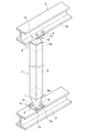
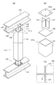
図1は、本発明を適用した金属製中空ジョイント1により、H形鋼からなる構造部材3と角形鋼管5の端部5aとを接合した接合構造2を示す斜視図である。本発明の金属製中空ジョイント1を用いた接合構造2は、異なる二方向に延長されてなる構造部材のうちの、一方の構造部材として構成される角形鋼管5の端部5aと他方の構造部材3とが交差する交差部9において用いられるものである。
FIG. 1 is a perspective view showing a
この角形鋼管5と接合される他方の構造部材3は、金属製中空ジョイント1に取り付けられるエンドプレート31を当接させてこれらをボルト接合可能なものから構成されていればよい。この他方の構造部材3としては、例えば、H形鋼、L形鋼、C形鋼、ボックス形鋼等の各種断面形状からなる形鋼部材や、鋼板等の板状部材が挙げられる。
The other
本発明に係る金属製中空ジョイント1は、このような角形鋼管5と構造部材3とを有する構造物であれば、建築構造物、機械構造物等を問わず、いかなるものに適用してもよい。本発明の適用の対象となる構造物について例示すると、例えば、柱、梁、ブレース等を有する鉄骨造の建築構造物や、ピラー、メンバ、バンパー等を有する乗用車、建設機械の車体のような骨組構造の機械構造物が挙げられる。
The metal hollow joint 1 according to the present invention may be applied to any structure as long as it has such a
本実施形態においては、角形鋼管5が鉛直方向に延長された柱部材として配置され、構造部材3が上下に間隔を空けて設けられ、水平方向に延長された梁部材として配置された建築構造物に金属製中空ジョイント1を用いる場合を例にとって説明する。
In the present embodiment, the
金属製中空ジョイント1が取り付けられて構成される角形鋼管部材7は、図1に示すように、断面角形状の角形鋼管5と、角形鋼管5の両側の端部5aに取り付けられる金属製中空ジョイント1とを備えるものである。
As shown in FIG. 1, the rectangular
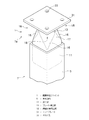
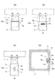
図2は、角形鋼管部材7の端部7aの拡大斜視図であり、図3は、その分解斜視図である。図4は、本発明を適用した金属製中空ジョイント1の第1実施形態を示しており、図4(a)はその斜視図、(b)はその平面図、(c)は(a)のA−A線断面図を示している。図5は、図2における平面図を示している。
2 is an enlarged perspective view of the
金属製中空ジョイント1は、図4に示すように、全体として筒状に形成されたジョイント本体10からなるものであり、ジョイント本体10の軸方向の一端側10aに設けられた装入部11と、ジョイント本体10の軸方向の他端側10bに設けられたプレート接合部13と、装入部11とプレート接合部13との間に設けられた縮径部17とを備えている。金属製中空ジョイント1は、後述のハイドロフォーム成形、プレス成形等によって成形されるものである。金属製中空ジョイント1は、成形加工が可能であれば特にその材質について限定するものではなく、例えば、鋼、アルミ、チタン等の金属から構成される。
As shown in FIG. 4, the metal
この金属製中空ジョイント1は、図4(a)に示すような、ジョイント本体10の一端側10a端部から他端側10bにかけての範囲R1の部位の断面形状と、ジョイント本体10の他端側10b端部から一端側10aにかけての範囲R3の部位の断面形状とがほぼ一様とされている。この範囲R1の部位と範囲R3の部位との間に位置する範囲R2の部位の形状は、ジョイント本体10の一端側10aから他端側10bに向かうにつれて、範囲R1の部位の断面形状から範囲R3の部位の断面形状に近づくように、徐々に軸心Gに向けて狭まって形成されている。図4の例では、この範囲R2の部位において、範囲R1の角形断面の角部12aから範囲R3の角形断面の側面部14bに近づくように、傾斜面16が形成され、範囲R3の角形断面の角部14aから範囲R1の角形断面の側面部12bにかけては略同一平面上に位置するように形成されている。本明細書においては、この範囲R1の部位を装入部11とし、範囲R2の部位を縮径部17とし、範囲R3の部位をプレート接合部13として扱う。
As shown in FIG. 4A, the metal
プレート接合部13には、図2、図3に示すように、その他端側10bの端面13aに対して、複数のボルト孔33が形成された鋼板等からなる平板状のエンドプレート31の一面側が突き合わされ、これらが溶接等によって固着されることになる。エンドプレート31も、例えば、鋼、アルミ、チタン等の金属から構成される。
As shown in FIGS. 2 and 3, the
金属製中空ジョイント1は、図2、図3に示すように、その装入部11を角形鋼管5の端部5aの開口に装入することによって用いられ、装入後において、後述の固定構造により角形鋼管5に対して固定される。
2 and 3, the metal
装入部11は、図4(c)、図5に示すように、角形鋼管5の形状に応じた形状とされている。具体的には、装入部11は、角形鋼管5に対して装入可能となるように、角形鋼管5の内形と略同一の外形となる断面角形状に形成されている。換言すると、角形鋼管5の断面形状と装入部11の断面形状とはほぼ同様の角形断面とされていることになる。
As shown in FIGS. 4C and 5, the charging
装入部11は、これを角形鋼管5内に装入した場合において、装入部11の角形断面の各辺が角形鋼管5の内周面に接触していてもよいし、接触していなくもよい。装入部11の角形断面の各辺が角形鋼管5の内周面に接触していない場合で、金属製中空ジョイント1と角形鋼管5とを後述の溶接により固定する場合、その間に生じる隙間を溶接によって埋めるようにしてもよい。
When the charging
プレート接合部13は、図4(a)〜(c)に示すように、装入部11の角形断面がなす角部12aから、ジョイント本体10の軸心Gを中心として略45度回転させた位置に角部14aを有する断面角形状に形成されている。なお、本実施形態では、装入部11とプレート接合部13との何れの断面形状も略正方形状に形成されている。
As shown in FIGS. 4 (a) to 4 (c), the plate
プレート接合部13は、図4(a)〜(c)に示すように、所定部位において、装入部11よりもその内側に狭まって形成されている。これは、図4(c)に示すように、ジョイント本体10の軸方向から見た場合におけるプレート接合部13の断面外形が、装入部11の断面外形よりも小さくなるように、その装入部11の断面外形よりもジョイント本体10の軸心Gに向けて狭まって形成されていることを意味している。
As shown in FIGS. 4A to 4C, the plate
このように形成された金属製中空ジョイント1は、図6(a)に示すように、その装入部11側からジョイント本体10を角形鋼管5内に装入した場合に、ジョイント本体10の装入部11の外周よりも外側に突出した部分がないことから、角形鋼管5の軸方向にスライド可能に装入されることになる。
As shown in FIG. 6A, the metal hollow joint 1 formed in this way has the
このプレート接合部13の狭まって形成されている部位は、図5に示すように、エンドプレート31に形成されているボルト孔33に対応した部位とされている。本実施例では、略正方形状のエンドプレート31の四隅の角部近傍にボルト孔33が形成されており、このボルト孔33近傍にスペースが設けられるように、プレート接合部13が装入部11よりも内側に狭まって形成されている。
As shown in FIG. 5, the narrowed portion of the plate joint 13 is a portion corresponding to the
これにより、図2、図5に示すように、エンドプレート31と縮径部17の傾斜面16との間において、エンドプレート31のボルト孔33へ挿通されるボルトや、これに螺合されるナットの締結作業を容易とする締結作業用空間18が形成されることになる。この締結作業用空間18では、ボルトナットの締結作業時において、作業員がボルトナットを手動で配置するのに利用したり、ソケットレンチやインパクトレンチのソケットのような締結工具の一部を配置したりすることができる。
As a result, as shown in FIGS. 2 and 5, between the
このプレート接合部13の形状が狭まる度合いは、狭まることにより設けられるスペースで、エンドプレート31のボルト孔33で用いられるボルトナットの締結作業が可能となる程度に調整されていればよい。
The degree to which the shape of the plate joint 13 is narrowed may be a space provided by the narrowing, and may be adjusted to such an extent that the bolt nut used in the
このような構成からなる金属製中空ジョイント1を用いて、H形鋼からなる構造部材3と角形鋼管5の端部5aとを接合する場合の作業手順の一例について説明する。
An example of a work procedure in the case of joining the
まず、工場にて、金属製中空ジョイント1のプレート接合部13の端面13aにエンドプレート31を固着しておく。次に、接合しようとする角形鋼管5の両端に対してこの金属製中空ジョイント1の装入部11を装入する。この後、これら金属製中空ジョイント1を角形鋼管5の軸方向にスライドさせて、角形鋼管5の端部5aからの金属製中空ジョイント1の突出長さを、角形鋼管5の端部5aからこれを接合すべき構造部材3までの間隔に対応させて調整して、後述の固定構造により金属製中空ジョイント1を固定する。そして施工現場ににてエンドプレートと構造部材3のフランジ3aとをボルト接合して、構造部材3と角形鋼管5とが接合されることになる。
First, the
このような構成からなる金属製中空ジョイント1の作用効果について説明する。 The effect of the metal hollow joint 1 having such a configuration will be described.
本発明における金属製中空ジョイント1は、図6(a)に示すように、角形鋼管5に対してその軸方向にスライド可能に装入されるため、金属製中空ジョイント1の角形鋼管5の端部5aからの突出長さを調整することが可能となっている。このため、角形鋼管5の端部5aからこれを接合すべき構造部材3までの間隔に対応させて、角形鋼管部材7の仕上げ長さを調整することが可能となっている。このため、角形鋼管部材7の軸方向長さの寸法精度の確保が容易になるとともに、仕上げ長さ一つ一つに対して、角形鋼管5の長さを調整する精密加工の必要がなくなるため、注文或いはストックする角形鋼管5の寸法を集約することができ、保管性が高まることになる。また、金属製中空ジョイント1の角形鋼管5の端部5aからの突出長さを調整することが可能となったことにより、事前に工場で長さを調整する場合だけでなく、既存建物の耐震補強をする場合など、施工現場にて長さの調整が必要な場合は容易に対応が可能となる。
As shown in FIG. 6 (a), the metal hollow joint 1 in the present invention is inserted into the
また、本発明における金属製中空ジョイント1は、金属製中空ジョイント1の装入部11とこれが装入される角形鋼管5とがほぼ同様の中空の角形断面であるため、溶接線の増加や応力集中の影響を抑えることが可能となる。
Further, the metal hollow joint 1 according to the present invention has a hollow square cross section in which the
また、本発明における金属製中空ジョイント1は、筒状に形成されているジョイント本体10のプレート接合部13が、エンドプレート31のボルト孔33の位置に対応した部位において、装入部11よりもその内側に狭まって形成されており、これによって、エンドプレート31と縮径部17の傾斜面16との間においてボルトナットの締結作業用空間18が形成された構成とされている。このように構成された金属製中空ジョイント1は、ボルトナットの締結作業用空間18を比較的広く得つつも、軸心Gの外側に広く断面を確保可能な形状とされている。また、角形鋼管5の端部5aにこれとは別部材の金属製中空ジョイント1を装入させる構成とされていることから金属製中空ジョイント1のみを高強度薄肉化させることができる。これによって、金属製中空ジョイント1を軽量化させて角形鋼管部材7や、角形鋼管部材7を有する構造物全体の軽量化を図ることが可能となる。
Further, the metal hollow joint 1 according to the present invention has a plate
また、本発明における金属製中空ジョイント1は、これが取り付けられた角形鋼管部材7が、図21に示される角形鋼管部材110よりも部材数が少ないうえ、少ない溶接回数で組立作業が完了するため、作業に要する期間、費用の点から優れたものとなっている。また、本発明における金属製中空ジョイント1は、これが取り付けられた角形鋼管部材7が、エンドプレート31以外に外側に突出した部材がないので、仕上げ材等を取り付ける際の障害とならず、設計の自由度を向上させることが可能となっている。
Moreover, since the square
因みに、角形鋼管5と金属製中空ジョイント1は同一で角形鋼管部材7の長さ寸法に対応させる場合、例えば、図6(b)、図6(c)に示すように、角形鋼管5の長さはそのままで、金属製中空ジョイント1の挿入長さを変えることで、角形鋼管部材7の長さ寸法に対応させることができる。
Incidentally, when the
次に、本発明を適用した金属製中空ジョイントの第2実施形態〜第4実施形態について説明する。なお、上述した構成要素と同一の構成要素については、同一の符号を付すことにより以下での説明を省略する。 Next, 2nd Embodiment-4th Embodiment of the metal hollow joint to which this invention is applied is described. In addition, about the component same as the component mentioned above, the description below is abbreviate | omitted by attaching | subjecting the same code | symbol.
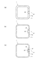
図7は、第2実施形態の金属製中空ジョイント1Aを示しており、図7(a)はその斜視図、(b)はその平面図、(c)は(a)のB−B線断面図を示している。 7A and 7B show a metal hollow joint 1A according to the second embodiment. FIG. 7A is a perspective view thereof, FIG. 7B is a plan view thereof, and FIG. 7C is a cross-sectional view taken along line BB in FIG. The figure is shown.
金属製中空ジョイント1Aは、第1実施形態として図4で示される金属製中空ジョイント1と比較して、プレート接合部13の断面形状が断面円形状に形成されている点において相違している。本実施形態での金属製中空ジョイント1Aにおけるプレート接合部13は、図7(c)に示すように、その円形断面がなす円の直径が、装入部11の正方形状の角形断面がなす側辺の長さより若干短くなるようにされている。
The metal hollow joint 1A is different from the metal hollow joint 1 shown in FIG. 4 as the first embodiment in that the cross section of the plate joint 13 is formed in a circular cross section. As shown in FIG. 7C, the plate joint 13 in the metal hollow joint 1 </ b> A according to the present embodiment is such that the circle formed by the circular cross section is formed by the square cross section of the charging
図8は、第3実施形態の金属製中空ジョイント1Bを示しており、図8(a)はその斜視図、(b)はその平面図、(c)は(a)のC−C線断面図を示している。 8A and 8B show a metal hollow joint 1B according to the third embodiment. FIG. 8A is a perspective view thereof, FIG. 8B is a plan view thereof, and FIG. 8C is a cross-sectional view taken along the line CC of FIG. The figure is shown.
金属製中空ジョイント1Bは、第1実施形態として図4で示される金属製中空ジョイント1と比較して、プレート接合部13の断面形状が相違している。具体的には、金属製中空ジョイント1Bのプレート接合部13は、断面角形状に形成されており、その角形断面がなす角部14a間に形成される側面部14bが、内側に湾曲して凹むように形成されている。
The metal hollow joint 1B is different from the metal hollow joint 1 shown in FIG. 4 as the first embodiment in the cross-sectional shape of the plate joint 13. Specifically, the plate
図9は、第4実施形態の金属製中空ジョイント1Cを示しており、図9(a)はその斜視図、(b)はその平面図、(c)は(a)のD−D線断面図を示している。 9A and 9B show a metal hollow joint 1C according to the fourth embodiment. FIG. 9A is a perspective view thereof, FIG. 9B is a plan view thereof, and FIG. 9C is a cross-sectional view taken along the line DD of FIG. The figure is shown.
金属製中空ジョイント1Cは、第1実施形態として図4で示される金属製中空ジョイント1と比較して、装入部11及びプレート接合部13の断面形状が相違している。具体的には、金属製中空ジョイント1Cの装入部11の断面形状は、略長方形状に形成されており、更に、そのプレート接合部13の断面形状は、略菱形状に形成されている。なお、金属製中空ジョイント1Cは、装入部11の長方形断面がなす弱軸方向とプレート接合部13の菱形断面がなす長辺側の対角線の延長方向とが略同一となるような形状とされている。
Compared to the metal hollow joint 1C shown in FIG. 4 as the first embodiment, the metal hollow joint 1C is different in the cross-sectional shapes of the
これらの第2実施形態〜第4実施形態に示される金属製中空ジョイント1A、1B、1Cは、何れも装入部11がなす角形断面の四隅の角部12aの上側にエンドプレート31のボルト孔33が配置され、図5に示すような態様で金属製中空ジョイント1A、1B、1Cを用いることを前提としている。これらの金属製中空ジョイント1A、1B、1Cのプレート接合部13は、何れも、ボルト孔31に対応した部位において、装入部11よりもその内側に狭まって形成されており、これにより、エンドプレート31と縮径部17の傾斜面16との間において締結作業用空間18が形成されることになる。
The metal
本発明に係る金属製中空ジョイント1は、プレート接合部13の形状が、少なくともボルト孔33の位置に対応した部位において、装入部11よりも内側に狭まって形成されていればよく、ボルト孔33と対応していない部位においても、装入部11よりも内側に狭まって形成されていてもよい。このため、プレート接合部13の断面形状については、上述の形状に特に限定するものではなく、断面三角形状、断面多角形状、断面半円形状、断面不定形状等の如何なるものであってもよい。
The metal hollow joint 1 according to the present invention only needs to be formed so that the shape of the plate
なお、第1実施形態〜第4実施形態の金属製中空ジョイント1、1A、1B、1Cのように、プレート接合部13は、装入部11がなす角形断面の四隅の角部12aに対応した部位において、その装入部11よりも内側に狭まって形成されていることが好ましい。これにより、プレート接合部13の断面二次モーメントを比較的大きく確保しつつも、締結作業用空間18を四箇所確保することが可能となる。
In addition, like the metal
なお、第1実施形態から第4実施形態における金属製中空ジョイント1、1A、1B、1Cの寸法の例について説明すると、第1実施形態における金属製中空ジョイント1は、図4(b)に示される装入部11が一辺52mの略正方形状で、プレート接合部13が一辺36mmの略正方形状で、図4(a)に示されるジョイント本体10の一端側10a端部からの装入部11の高さが50mmで、ジョイント本体10の一端側10a端部から他端側10b端部までの高さが105mmである。第2実施形態における金属製中空ジョイント1Aは、図7(b)に示されるプレート接合部13が直径50mmの略円形状である以外は、第1実施形態の金属製中空ジョイント1と同じである。第3実施形態における金属製中空ジョイント1Bは、図8(b)に示されるプレート接合部13の断面形状がなす最狭幅部の長さL2が35mmである以外は、第1実施形態の金属製中空ジョイント1とほぼ同じである。第4実施形態における金属製中空ジョイント1Cは、図9(b)に示される装入部11が50mm×80mmの略長方形状で、プレート接合部13の菱形断面がなす長辺側の対角線が60mmで、その短辺側の対角線が45mmで、図9(a)に示されるジョイント本体10の一端側10a端部からの装入部11の高さが30mmで、ジョイント本体10の一端側10端部から他端側10bまでの高さが105mmである。これら寸法は、あくまで一例として示したものであり、本発明に係る金属製中空ジョイント1は、これら寸法に限定されないのは勿論である。
In addition, the example of the dimension of the metal
次に、上述のような構成からなる金属製中空ジョイント1の製造方法について説明する。 Next, a method for manufacturing the metal hollow joint 1 having the above-described configuration will be described.
本発明に係る金属製中空ジョイント1は、例えば、ハイドロフォーム成形、プレス成形等により製造されるが、ハイドロフォーム成形のような一体成形により製造することが好ましい。以下においては、ハイドロフォーム成形により図7に示される金属製中空ジョイント1Aを製造する方法の一例について説明する。 The metal hollow joint 1 according to the present invention is manufactured, for example, by hydroforming, press molding, or the like, but is preferably manufactured by integral molding such as hydroforming. Below, an example of the method of manufacturing metal hollow joint 1A shown by FIG. 7 by hydroforming is demonstrated.
図10(a)は、本発明における金属製中空ジョイント1Aの製造方法を実現可能とするハイドロフォーム成形装置50の構成を模式的に示した側面断面図である。
Fig.10 (a) is side sectional drawing which showed typically the structure of the hydrofoam shaping |
ハイドロフォーム成形装置50は、一組のハイドロフォーム用分割金型51、52と、分割金型51及び分割金型52間に配置される素材管57を両端から軸押し可能とする軸押しパンチ55とを備えている。なお、本明細書においては、上側に配置される分割金型51を上金型51とし、下側に配置される分割金型52を下金型52として説明する。また、ここでいう素材管57とは、ハイドロフォーム成形後に得られる成形品の素材となる鋼管、アルミ管、チタン管等の金属管のことをいう。
The
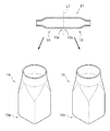
上金型51及び下金型52は、ハイドロフォーム成形により素材管57を所定形状にするためのキャビティ53が設けられている。本例においては、このキャビティ53によって素材管57が、図7に示される金属製中空ジョイント1Aを二つ直列に配置し、その軸方向の一端側10a端部を突き合わせた形状に成形可能となるように、キャビティ53の形状が調整されている。なお、図11においては、この上金型51及び下金型52を用いて成形されたハイドロフォーム成形品61の形状の側面断面図を示している。得られるハイドロフォーム成形品61は、その軸方向中心の両側が対称となるような形状とされている。
The
キャビティ53は、素材管57の両端側に対応する位置に設けられる半円形凹部53aと、素材管57の中央部に対応する位置に設けられる方形凹部53bと、半円形凹部53aと方形凹部53bとの間に設けられ、半円形凹部53aから方形凹部53bに向かうにつれて形状が半円形から方形に近づくように滑らかに拡開される拡開凹部53cとを備えて構成されている。
The
このハイドロフォーム成形装置50によって金属製中空ジョイント1Aを製造する場合、まず、素材管57を下金型52のキャビティ53内に素材管57を配置して、上金型51を下降させて蓋を閉める。次に、図10(b)に示すように、図示しない圧力媒体充填手段により、例えば水のような圧力媒体59を素材管57内に充填して、その圧力媒体59により素材管57の内側から外側に向けて液圧を負荷するととともに、素材管57の両端から軸押しパンチ55によって素材管57を軸押しして圧縮荷重を負荷して、軸押し及び液圧の付与によるハイドロフォーム成形を施す。
When the metal hollow joint 1A is manufactured by the
図10(c)は、図10(b)のE−E線断面図、G−G線断面図を示し、図10(d)は、図10(b)のF−F線断面図を示している。この図に示すように、ハイドロフォーム成形により、素材管57の両端側は、上金型51及び下金型52のキャビティ53の半円形凹部53aにより断面円形状に形成され、素材管57の中央部は、キャビティ53の方形凹部53bにより断面角形状に形成されることになる。
10C shows a cross-sectional view taken along line EE and GG in FIG. 10B, and FIG. 10D shows a cross-sectional view taken along line FF in FIG. 10B. ing. As shown in this figure, both ends of the
次に、図11に示すように、ハイドロフォーム成形により得られたハイドロフォーム成形品61をその軸方向の中央で二分割されるように、一点鎖線で示した切断線L1に沿って切断する。これによって、金属製中空ジョイント1Aが二つ得られることになる。
Next, as shown in FIG. 11, the hydroform molded
上述のように、ハイドロフォーム成形により本発明に係る金属製中空ジョイント1を製造する場合、他の成形方法により製造した場合と比べて、本発明に係る金属製中空ジョイント1のような複雑形状のものであっても容易に製造することができる。また、本発明に係る金属製中空ジョイント1は、溶接を用いない一体成形により得られているため、溶接歪みによる仕上がり寸法精度、強度への悪影響がなく、また、外観に切断線等がないことから意匠性の観点からも優れている。 As described above, when the metal hollow joint 1 according to the present invention is manufactured by hydroforming, as compared with the case where the metal hollow joint 1 according to the present invention is manufactured by other forming methods, the metal hollow joint 1 according to the present invention has a complicated shape. Even if it is a thing, it can manufacture easily. Moreover, since the metal hollow joint 1 according to the present invention is obtained by integral molding without using welding, there is no adverse effect on the finished dimensional accuracy and strength due to welding distortion, and there is no cutting line or the like in the appearance. From the viewpoint of designability.
また、軸方向中心の両側で対称となるような形状のハイドロフォーム成形品61を、その軸方向の中央で二分割されるように切断して二つの金属製中空ジョイント1を得る場合、一組の上金型51及び下金型52のキャビティ53から同一形状の二つの金属製中空ジョイント1を得ることができ、量産性に優れたものとなっている。また、この場合、ハイドロフォーム成形の特性上、素材管57の中央側よりも両端側の方が板厚を厚くすることができることから、金属製中空ジョイント1の装入部11よりもプレート接合部13の板厚の方を厚くすることが可能となるため、エンドプレート31への溶接によるひずみを抑えることができる。
In addition, when two hydro
因みに、軸方向中心の両側で対称となるような形状のハイドロフォーム成形品61を、軸方向中心以外の部位でその軸方向に二分割されるように切断して、異なる高さの二つの金属製中空ジョイント1を得ることとしてもよい。この場合、金属製中空ジョイント1の装入部11に相当する部位において、得られたハイドロフォーム成形品61を切断することになる。
Incidentally, the hydroform molded
なお、上述のハイドロフォーム成形装置50やハイドロフォーム成形工程は、金属製中空ジョイント1を製造する方法の一例として説明したものであり、上述の構成、工程順に限定されるものではない。このため、例えば、一組の上金型51、下金型52によって、金属製中空ジョイント1が一つのみ成形されるようにしてもよい、三つ以上成形されるようにしてもよい。なお、図10、図11に示されるように、軸方向中心の両側で対称となるような形状のハイドロフォーム成形品61から二つの金属製中空ジョイント1を得る場合、素材管57の両側からの軸押しパンチ55による軸押しの圧縮荷重を均等にすることができ、安定してハイドロフォーム成形品61を得ることができるメリットがある。
In addition, the above-mentioned hydroform shaping |
一組の上金型51、下金型52によって、金属製中空ジョイント1を三つ以上成形されるようにする場合、上金型51、下金型52のキャビティ53は、例えば、金属製中空ジョイント1を複数直列に配置し、互いに隣り合う金属製中空ジョイント1が何れか一方の端部を突き合わせた形状となるように調整されていてもよい。この場合、図7に示される金属製中空ジョイント1Aを複数成形する場合を例にとると、キャビティ53は、半円形凹部53a、拡開凹部53c、方形凹部53b並びに拡開凹部53cを一単位とした形状が、軸方向に連続して設けられることになる。
When three or more metal
また、本発明におけるハイドロフォーム成形装置、ハイドロフォーム成形方法においては、公知のハイドロフォーム成形装置で用いられている如何なる機構が採用されていてもよいし、公知のハイドロフォーム成形方法で用いられている如何なる手段が採用されていてもよい。 Further, in the hydroform molding apparatus and hydroform molding method of the present invention, any mechanism used in a known hydroform molding apparatus may be employed, and it is used in a known hydroform molding method. Any means may be adopted.
次に、プレス成形を用いた場合の本発明に係る金属製中空ジョイント1の製造方法について説明する。以下においては、プレス成形により図4に示される金属製中空ジョイント1を製造する方法の一例で、金属製中空ジョイント1として鋼製中空ジョイントを用いた場合の例について説明する。
Next, the manufacturing method of the metal hollow joint 1 according to the present invention when press molding is used will be described. In the following, an example in which a steel
まず、予め打ち抜き加工により所定形状に打ち抜かれた板材に対して、プレス成形を施すことにより図12(a)に示すようなプレス成形品63を二つ得る。このプレス成形品63は、図12(b)に示すように、鋼製中空ジョイント1をその軸方向から見た場合における断面形状が軸心Gの両側で対称となるように、その軸方向に沿って分断された形状からなる。
First, two press-formed
このようにして得られた二つのプレス成形品63は、図12(b)、図12(c)に示すように、その幅方向の両側の側端面63aを突き合わせたうえで、二部材の境界部65に沿ってレーザー溶接、アーク溶接等の溶接を施して、これらを互いに固定し、これによって鋼製中空ジョイント1が得られる。なお、図12(b)、図12(c)における斜線で示す範囲は溶接ビード74を示している。
As shown in FIGS. 12B and 12C, the two press-formed
このようにプレス成形によっても本発明に係る金属製中空ジョイント1が製造可能である。 Thus, the metal hollow joint 1 according to the present invention can also be manufactured by press molding.
次に、本発明に係る金属製中空ジョイント1を角形鋼管5に固定するための固定手段について説明する。
Next, a fixing means for fixing the metal hollow joint 1 according to the present invention to the
金属製中空ジョイント1を角形鋼管5に固定する固定手段としては、例えば、溶接、ボルト等による固定が挙げられる。
Examples of fixing means for fixing the metal hollow joint 1 to the
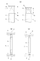
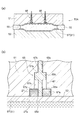
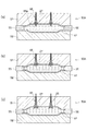
図13(a)、図13(b)は、その固定手段として溶接による固定を採用した場合の固定構造の一例で、金属製中空ジョイント1として鋼製中空ジョイントを用いた場合の例を示す側面図である。
FIG. 13A and FIG. 13B are examples of a fixing structure when welding fixing is used as the fixing means, and a side view showing an example in which a steel hollow joint is used as the metal
図13(a)に示される固定構造70Aは、角型鋼管5内に装入された鋼製中空ジョイント1のジョイント本体10の側面10cと、角形鋼管5の端面5bとの境界に沿って隅肉溶接を施すことによって構成される。
The fixed structure 70 </ b> A shown in FIG. 13A has corners along the boundary between the
図13(b)に示される固定構造70Bは、角形鋼管5の側面5cに予め形成された溶接用孔71と、角形鋼管5内に装入された鋼製中空ジョイント1のジョイント本体10の側面10cとの境界に沿って隅肉溶接を施すことによって構成される。
A fixing structure 70 </ b> B shown in FIG. 13 (b) includes a
なお、図13(b)に示される例における溶接用孔71は、角形鋼管5の周方向に延長された形状の長孔とされている。この溶接用孔71の形状は、角形鋼管5の周方向に延長された形状の長孔に限定するものではなく、角形鋼管5の軸方向に延長されていてもよいし、円形状とされていてもよい。また、図13(a)、(b)における斜線で示す範囲は、溶接ビード73を示している。
The
図13(a)に示される固定構造70Aの場合、角形鋼管5に対して何も加工することなく、鋼製中空ジョイント1を固定することができるが、角形鋼管の小口面にすみ肉溶接しなければならないので、溶接姿勢、習熟度が必要となる。これに対して、図13(b)に示される固定構造70Bの場合、角形鋼管5に対して溶接用孔71を設ける加工の必要があるが、孔を埋める溶接となるので、比較的溶接姿勢は確保しやすく習熟度が低くても溶接による固定を行なえるというメリットがある。
In the case of the fixing
図13(c)、図13(d)は、固定手段として着脱可能なボルトによる固定を採用した場合の固定構造の一例を示すものであり、図13(c)が固定構造70Cの側面図、図13(d)がそれとは異なる固定構造70Dの平面断面図である。
13 (c) and 13 (d) show an example of a fixing structure in the case where fixing by a detachable bolt is adopted as the fixing means, and FIG. 13 (c) is a side view of the fixing
図13(c)に示される固定構造70Cは、角形鋼管5の軸方向に延長されてその角形鋼管5の側面5cに形成された長孔75と、図14に示すように、金属製中空ジョイント1の装入部11の側面11aに形成され、その内壁面にねじ切り加工が施された雌ねじ孔21とを貫通するボルト77のボルト接合により構成されている。
A fixing
この固定構造70Cにおいては、角形鋼管5の端部5aからの金属製中空ジョイントの突出長さを調整した後に、金属製中空ジョイント1の雌ねじ孔21の位置が角形鋼管5の長孔75の範囲内に含まれるように、角形鋼管5の軸方向に延長される長孔75の長さが調整されている。このため、金属製中空ジョイント1の突出長さの調整範囲が広がり、角形鋼管5と金属製中空ジョイント1とをより確実に固定することが可能となっている。
In this fixed structure 70 </ b> C, after adjusting the protruding length of the metal hollow joint from the
因みに、この金属製中空ジョイント1に形成された雌ねじ孔21は、図14(a)、図14(b)に示すように、一つ又は二つ設けられていてもよいし、これ以上の数設けられていてもよい。 Incidentally, one or two female screw holes 21 formed in the metal hollow joint 1 may be provided as shown in FIGS. 14 (a) and 14 (b), or more than this. It may be provided.
図15は、この雌ねじ孔21の形状を示す平面断面図である。金属製中空ジョイント1の板厚が十分に厚く、ボルト77との螺合長さを確保できる場合は、図15(a)に示すように、装入部11の側面11aを貫通する貫通孔23を形成させ、この孔内壁面にねじ切り加工を施し、これを雌ねじ孔21としてもよい。
FIG. 15 is a plan sectional view showing the shape of the
金属製中空ジョイント1の板厚が薄い場合は、図15(b)に示すように、貫通孔23を有して装入部11の内側に向けて突出された筒状突起25を形成させ、この筒状突起25の貫通孔23の孔内壁面にねじ切り加工を施し、これを雌ねじ孔21としてもよい。これにより、板厚の薄い金属製中空ジョイント1でもボルト77との螺合長さを確保可能となる。
When the plate thickness of the metal
また、この他にも、図15(c)に示すように、筒状突起25の貫通孔23内に、ナットのような雌ねじ部材27を埋め込み配置し、これを雌ねじ孔21としてもよい。この雌ねじ部材27は、後述の方法により、ハイドロフォーム成形時に貫通孔23内で埋め込まれて固定されるものである。
In addition, as shown in FIG. 15 (c), a
図13(d)に示される固定構造70Dは、ボルト頭部79aの底面に略円錐台形状のテーパー面79bが形成された皿ボルト79と、角形鋼管5の側面5cに形成され、皿ボルト79のテーパー面79bに応じた形状のテーパー面81aが設けられたザグリ孔81と、金属製中空ジョイント1の装入部11の側面11aに形成された雌ねじ孔21とを備え、ザグリ孔81及び雌ねじ孔21を貫通する皿ボルト79でのボルト接合により構成される。ボルト接合後においては、ザグリ孔81内に配置される皿ボルト79のボルト頭部79aが総てザグリ孔81内に収容されるように調整されている。
A fixing
これによって、角形鋼管5に対して金属製中空ジョイント1を固定した後において、ボルト頭部79aが角形鋼管5の外側に突出せず、仕上げ材等を取り付ける際の障害とならず、設計の自由度を向上させることができる。
Thus, after the metal
図13(c)、(d)に示すような、着脱可能なボルトによる固定構造を採用した場合、工場等での製造段階で、角形鋼管5の端部5aに予め金属製中空ジョイント1をボルトにより仮固定しておき、施工現場にてボルトを取り外して金属製中空ジョイント1の突出長さの調整を行なうことが可能となり、金属製中空ジョイント1と角形鋼管5とを別管理する必要がなくなり、保管性に優れたものとなる。
When a fixing structure using detachable bolts as shown in FIGS. 13C and 13D is adopted, the metal
なお、角形鋼管5と金属製中空ジョイント1との固定構造は、上述の例に限定されるものではなく、例えば、いかなる位置に溶接、ボルト等による固定部を設けてもよいし、この他にも本発明を逸脱しない範囲で如何なる公知の固定手段を採用してもよい。また、ボルトによる固定構造を採用する場合、ワンサイドボルトを用いることによって、雌ねじ孔21の内周面にねじ切り加工を施さずに省略することとしてもよい。
In addition, the fixing structure of the
次に、上述の雌ねじ部材27を筒状突起25の貫通孔23内にハイドロフォーム成形時に埋め込み配置する方法について説明する。
Next, a method for embedding and arranging the above-described
図16(a)は、ハイドロフォーム成形時に雌ねじ部材27を埋め込み配置可能とするハイドロフォーム成形装置50Aにより、素材管57に対して軸押し及び液圧の付与によるハイドロフォーム成形を施した後の状態を示す側面断面図である。
FIG. 16 (a) shows a state after hydroforming is performed by pushing the shaft and applying hydraulic pressure to the
このハイドロフォーム成形装置50Aは、図10(a)に示されるハイドロフォーム成形装置50と比較して、上金型51に素材管57を穿孔可能な穿孔手段としてのピアスパンチ65が組み込まれている点において相違している。図16(b)は、図16(a)におけるピアスパンチ65の拡大断面図を示している。
In this
このピアスパンチ65は、全体として円柱状に形成されており、その先端に設けられる先端部65aと、先端部65aよりも拡径されてなる中間部65bと、中間部65bよりも縮径されてなる基端部65cとを備えている。基端部65cよりも更に基端側においては、図示しないシリンダが設けられており、ピアスパンチ65は、そのシリンダにより軸方向の前後に動作可能とされている。
The piercing
ピアスパンチ65の先端部65aには、その外周において、先端部65aの外径よりも僅かに大きな内径からなる円筒状の雌ねじ部材27が嵌合されている。この雌ねじ部材27は、ナット等から構成され、予めその内周面にねじ切り加工が施されているものである。ピアスパンチ65の先端部65aは、雌ねじ部材27の内周面に摺動可能とされている。
A cylindrical
このピアスパンチ65は、上金型51に設けられたピアス穴67内に収容されている。ピアス穴67は、ピアスパンチ65の先端部65a側から基端部65c側にかけて順に縮径されて形成された先端部67aと、中間部67bと、基端部67cとを備えている。
The piercing
軸押し及び液圧の付与によるハイドロフォーム成形時においては、図16(b)に示すように、ハイドロフォーム成形品61が、上金型51のキャビティ53内に密着して、ピアスパンチ65及び雌ねじ部材27に対して、ハイドロフォーム成形品61の径方向外側に荷重が負荷されることになる。この場合において、雌ねじ部材27に対しては、ピアス穴67の先端部67aと中間部67bとの間の側面部67dが接触し、ピアスパンチ65に対しては、ピアス穴67の中間部67bと基端部67cとの間の側面部67eが接触し、雌ねじ部材27とピアスパンチ65とが上金型51から抜け出ないようにされている。
At the time of hydroform molding by pushing the shaft and applying hydraulic pressure, as shown in FIG. 16 (b), the hydroform molded
このピアスパンチ65を用いて雌ねじ部材27をハイドロフォーム成形品61に埋め込み配置する場合、軸押し及び液圧の付与によるハイドロフォーム成形後に、ハイドロフォーム成形品61内を高圧に保持したまま、図17(a)に示すように、雌ねじ部材27を通してピアスパンチ65をハイドロフォーム成形品61の内側に向けて前進させる。ピアスパンチ65の先端部65aの縁部65dは、図16(b)に示すように、鋭利に角ばって形成されており、ピアスパンチ65の前進に伴いその先端部65aによってハイドロフォーム成形品61に穴あけ加工が施され、貫通孔が形成される。
When the
次に、図17(b)に示すように、ピアスパンチ65をハイドロフォーム成形品61の内側に向けて更に前進させ、ピアスパンチ65の中間部65bによって雌ねじ部材27も前進させる。雌ねじ部材27の縁部27aは、図16(b)に示すように、丸みが形成されており、ピアスパンチ65の前進に伴い雌ねじ部材27によってハイドロフォーム成形品61にバーリング加工が施され、貫通孔を有する筒状突起25が形成される。
Next, as shown in FIG. 17B, the piercing
次に、ピアスパンチ65をハイドロフォーム成形品61の外側に向けて後退させると、図17(c)に示すように、バーリング加工により形成された筒状突起25の貫通孔内に雌ねじ部材27が埋め込まれた状態で残る。この後は、得られたハイドロフォーム成形品61をその軸方向中央で二分割することによって、雌ねじ部材27が埋め込み配置された金属製中空ジョイント1が得られる。
Next, when the piercing
このような方法を用いた場合、ハイドロフォーム成形の難易度を変えることなく、金属製中空ジョイント1を角形鋼管5にボルト接合するための雌ねじ孔21を得ることができ、量産性に優れたものとなっている。特に、雌ねじ部材27に予めねじ切り加工が施されていることから、ハイドロフォーム成形後に改めてねじ切り加工を施す手間を削減できる。
When such a method is used, an
なお、図示の例においてピアスパンチ65は、ハイドロフォーム成形品61の軸方向中心で対称となるように、二つ組み込まれており、この場合、得られる二つの金属製中空ジョイント1の雌ねじ孔21の位置が同一位置に形成されることになり、同一形状の製品を量産するうえで好ましい。
In the illustrated example, two piercing
また、このピアスパンチ65は、上金型51のみでなく、下金型52に組み込まれていてもよいのは勿論であるし、その組み込まれる数についても特段限定するものではない。また、ピアスパンチ65に雌ねじ部材27を設けず、ハイドロフォーム成形時に穴あけ加工のみを施すこととしてもよいし、図17(c)に示すように、ピアスパンチ65を後退させる際に雌ねじ部材27も同時に後退させて、ハイドロフォーム成形品61に穴あけ加工及びバーリング加工を施すのみとしてもよい。この場合、穴あけ加工、バーリング加工後に、穴あけ加工等によって得られた貫通孔にねじ切り加工を別途施してもよいのは勿論である。
The piercing
また、本発明における金属製中空ジョイント1は、以下のような構成が採用されていてもよい。 Moreover, the following structures may be employ | adopted for the metal hollow joint 1 in this invention.
図18は、ジョイント本体10の一端側10a端部において案内部29が形成された金属製中空ジョイント1の構成を示しており、(a)はその斜視図であり、(b)は(a)のH−H線断面図であり、(c)はその底面図である。
FIG. 18 shows the configuration of the metal hollow joint 1 in which the
案内部29は、ジョイント本体10の装入部11よりもその内側に狭まって形成されている。これにより、金属製中空ジョイント1を角形鋼管5内に装入する場合に、角形鋼管5の端部5aの開口よりも小さく形成されていることになる案内部29により金属製中空ジョイント1が角形鋼管5に対して案内されることになり、金属製中空ジョイント1の装入作業が容易となる。
The
また、この案内部29の外周には、図18(b)に示すように、ジョイント本体10の一端側10a端部に向うにつれてその内側に徐々に狭まるようなテーパー面29aが形成されている。これにより、金属製中空ジョイント1の装入作業が更に容易なものとなっている。なお、案内部29の外周には、テーパー面29aを設けず、装入部11との間に段差が設けられるように構成されていてもよい。
Further, as shown in FIG. 18B, a
また、本発明に係る金属製中空ジョイント1を用いた角形鋼管部材7は、以下のように建築構造物における梁、斜材として用いられていてもよい。
Moreover, the square
図19は、本発明に係る金属製中空ジョイント1を用いた角形鋼管部材7を、梁として用いた状態を示す斜視図である。
FIG. 19 is a perspective view showing a state in which the rectangular
この場合、角形鋼管5と接合されるべき他方の構造部材としての柱部材3Aは、鉛直方向に延長されて、水平方向に間隔を空けて配置されている。角形鋼管部材7は、その両端のエンドプレート31を、これら柱部材3Aに当接させてこれらをボルト接合することによって、梁として取り付けられることになる。
In this case, the
図20は、本発明に係る金属製中空ジョイント1を用いた角形鋼管部材7を、梁部材3が柱部材3Aに対して傾斜して配置される斜材として用いた状態を示す斜視図である。
FIG. 20 is a perspective view showing a state in which the rectangular
この場合、梁部材3と柱部材3Aとが交差する角部41の近傍に、一端側が梁部材3に溶接等により固着され、他端側が柱部材3Aに溶接等により固着された鋼板等からなる傾斜プレート3Bを設けておき、角形鋼管部材7の両端のエンドプレート31をこの傾斜プレート3Bに当接させてこれらをボルト接合することによって、角形鋼管部材7が斜材として取り付けられることになる。この場合、上述した角形鋼管5と接合されるべき他方の構造部材とは、この傾斜プレート3Bが対応している。
In this case, in the vicinity of the
因みに、傾斜プレート3Bと柱部材3Aと梁部材3とによって囲まれた部位には、図20に示すように、略三角形状の鋼板等からなる補強リブ43が、これら傾斜プレート3B等に対して溶接によって固着されている。
Incidentally, as shown in FIG. 20, a reinforcing
本発明を適用した金属製中空ジョイント、この製造方法及びこれを用いた角形鋼管部材は、上述した実施の形態に限定されるものではなく、本発明の要旨を逸脱しない範囲で適宜設計変更等されていてもよい。 The metal hollow joint to which the present invention is applied, the manufacturing method thereof, and the rectangular steel pipe member using the same are not limited to the above-described embodiments, and may be appropriately changed in design without departing from the gist of the present invention. It may be.
1 金属製中空ジョイント
2 接合構造
3 構造部材(梁部材)
3A 柱部材
3B 傾斜プレート
3a フランジ
5 角形鋼管
5a 端部
5b 端面
5c 側面
7 角形鋼管部材
9 交差部
10 ジョイント本体
10a 一端側
10b 他端側
10c 側面
11 装入部
11a 側面
12a 角部
12b 側面部
13 プレート接合部
13a 端面
13b 外周面
14a 角部
14b 側面部
16 傾斜面
17 縮径部
18 締結作業用空間
21 雌ねじ孔
23 貫通孔
25 筒状突起
27 雌ねじ部材
27a 縁部
29 案内部
29a テーパー面
31 エンドプレート
33 ボルト孔
41 角部
43 補強リブ
50 ハイドロフォーム成形装置
51 上金型
52 下金型
53 キャビティ
53a 半円形凹部
53b 方形凹部
53c 拡開凹部
55 軸押しパンチ
57 素材管
59 圧力媒体
61 ハイドロフォーム成形品
63 プレス成形品
63a 側端面
65 ピアスパンチ
65a 先端部
65b 中間部
65c 基端部
65d 縁部
67 ピアス穴
67a 先端部
67b 中間部
67c 基端部
67d 側面部
67e 側面部
70A〜D 固定構造
71 溶接用孔
73 溶接ビード
74 溶接ビード
75 長孔
77 ボルト
79 皿ボルト
81 ザグリ孔
100 接合構造
101 角形鋼管
103 構造部材
105 接合プレート
107 アングル部材
109 エンドプレート
109a ボルト孔
110 角形鋼管部材
111 締結作業用空間
G 軸心
L1 切断線
1 Metal hollow joint 2 Joining
3A Column member 3B Inclined plate 3a Flange 5 Square steel pipe 5a End 5b End face 5c Side face 7 Square steel pipe member 9 Intersection 10 Joint body 10a One end side 10b Other end side 10c Side face 11 Insertion part 11a Side face 12a Corner part 12b Side face part 13 Plate joint portion 13a End surface 13b Outer peripheral surface 14a Corner portion 14b Side surface portion 16 Inclined surface 17 Reduced diameter portion 18 Fastening work space 21 Female screw hole 23 Through hole 25 Cylindrical protrusion 27 Female screw member 27a Edge portion 29 Guide portion 29a Tapered surface 31 End Plate 33 Bolt hole 41 Corner portion 43 Reinforcing rib 50 Hydroform molding device 51 Upper die 52 Lower die 53 Cavity 53a Semicircular recess 53b Square recess 53c Expanding recess 55 Axial punch 57 Material tube 59 Pressure medium 61 Hydroform molding Product 63 Press-molded product 63a Side end face 65 Pier spa H 65a Tip portion 65b Intermediate portion 65c Base end portion 65d Edge portion 67 Piercing hole 67a Tip portion 67b Intermediate portion 67c Base end portion 67d Side surface portion 67e Side surface portions 70A to D Fixing structure 71 Welding hole 73 Weld bead 74 Weld bead 75 Long Hole 77 Bolt 79 Countersunk bolt 81 Counterbore hole 100 Joining structure 101 Square steel pipe 103 Structural member 105 Joining plate 107 Angle member 109 End plate 109a Bolt hole 110 Square steel pipe member 111 Fastening space G Axis L1 Cutting line
Claims (15)
上記ジョイント本体の軸方向他端側に設けられ、その他端側端面に対してボルト孔が複数形成されたエンドプレートが固着されるプレート接合部とを備え、
上記プレート接合部は、少なくとも上記ボルト孔の位置に対応した部位において、上記装入部よりもその内側に狭まって形成されていること
を特徴とする角形鋼管用金属製中空ジョイント。 A cylindrical joint body provided on one end side in the axial direction, and inserted into a square steel pipe with a rectangular cross section;
A plate joint provided on the other end side in the axial direction of the joint body, to which an end plate having a plurality of bolt holes formed on the other end side end face is fixed;
The metal plate hollow joint for a square steel pipe, wherein the plate joint portion is formed to be narrower on the inner side than the insertion portion at least in a portion corresponding to the position of the bolt hole.
を特徴とする請求項1に記載の角形鋼管用金属製中空ジョイント。 The metal hollow joint for a square steel pipe according to claim 1, wherein the joint body is integrally formed.
を特徴とする請求項1又は2に記載の角形鋼管用金属製中空ジョイント。 3. The plate joint portion is formed to be narrower on the inner side than the insertion portion at a portion corresponding to the corners of the four corners of the square cross section formed by the insertion portion. Metal hollow joint for square steel pipes as described in 1.
を特徴とする請求項1〜3の何れか1項に記載の角形鋼管用金属製中空ジョイント。 The square steel pipe according to any one of claims 1 to 3, further comprising a guide portion formed narrower on an inner side than the insertion portion at one end portion of the joint body. Metal hollow joint.
を特徴とする請求項4に記載の角形鋼管用金属製中空ジョイント。 5. The metal pipe for square steel pipe according to claim 4, wherein a tapered surface is formed on an outer periphery of the guide portion so as to gradually narrow toward an end portion on one end side of the joint body. Hollow joint.
を特徴とする請求項1〜5の何れか1項に記載の角形鋼管用金属製中空ジョイント。 The cylindrical portion having a threaded through-hole and projecting toward the inside thereof is formed in the insertion portion. 6. Metal hollow joint for rectangular steel pipe.
上記金属管に対して、軸押し及び液圧の付与によりハイドロフォーム成形を施し、
上記ハイドロフォーム成形された成形品をその軸方向に二分割すること
を特徴とする金属製中空ジョイントの製造方法。 A metal tube is disposed in a split mold for hydrofoam capable of forming the two hollow metal joints according to any one of claims 1 to 6 into a shape in which one end portion in the axial direction is abutted,
For the metal tube, hydroform molding is performed by applying axial pressure and hydraulic pressure,
A method for manufacturing a metal hollow joint, characterized in that the hydroformed molded product is divided into two in the axial direction.
上記金属管に対して、軸押し及び液圧の付与によりハイドロフォーム成形を施し、
上記ハイドロフォーム成形後に得られた成形品に、上記分割金型に設けられた穿孔手段によって、穴あけ加工とともにバーリング加工を施し、
上記バーリング加工された成形品をその軸方向に二分割し、
上記分割された成形品のバーリング加工による貫通孔にねじ切り加工を施すこと
を特徴とする金属製中空ジョイントの製造方法。 A metal tube is disposed in a split mold for hydrofoam capable of forming the two hollow metal joints according to any one of claims 1 to 6 into a shape in which one end portion in the axial direction is abutted,
For the metal tube, hydroform molding is performed by applying axial pressure and hydraulic pressure,
The molded product obtained after the hydroform molding is subjected to a burring process together with a drilling process by a punching means provided in the split mold,
The above burring processed product is divided into two in its axial direction,
A method for producing a metal hollow joint, characterized in that threading is performed on a through hole by burring of the divided molded product.
上記金属管に対して、軸押し及び液圧の付与によりハイドロフォーム成形を施し、
上記ハイドロフォーム成形後に得られた成形品に、上記分割金型に設けられた穿孔手段によって、穴あけ加工とともにバーリング加工を施し、
上記バーリング加工による貫通孔にねじ切り加工を施し、
上記ねじ切り加工された成形品をその軸方向に二分割すること
を特徴とする金属製中空ジョイントの製造方法。 A metal tube is disposed in a split mold for hydrofoam capable of forming the two hollow metal joints according to any one of claims 1 to 6 into a shape in which one end portion in the axial direction is abutted,
For the metal tube, hydroform molding is performed by applying axial pressure and hydraulic pressure,
The molded product obtained after the hydroform molding is subjected to a burring process together with a drilling process by a punching means provided in the split mold,
Apply threading to the through hole by the above burring process,
A method for producing a metal hollow joint, characterized in that the threaded molded product is divided into two in the axial direction.
上記金属管に対して、軸押し及び液圧の付与によりハイドロフォーム成形を施し、
上記ハイドロフォーム成形後に得られた成形品に、上記分割金型に設けられた穿孔手段によって、穴あけ加工とともにバーリング加工を施しつつ当該バーリング加工による貫通孔に雌ねじ部材を埋め込み配置し、
上記バーリング加工された成形品をその軸方向に二分割すること
を特徴とする金属製中空ジョイントの製造方法。 A metal tube is disposed in a split mold for hydrofoam capable of forming the two hollow metal joints according to any one of claims 1 to 6 into a shape in which one end portion in the axial direction is abutted,
For the metal tube, hydroform molding is performed by applying axial pressure and hydraulic pressure,
The molded product obtained after the hydroform molding is embedded by placing a female screw member in the through-hole formed by burring while performing burring with the drilling means provided in the split mold,
A method for manufacturing a metal hollow joint, characterized in that the burring-formed molded product is divided into two in the axial direction.
を特徴とする角形鋼管部材。 The insertion portion of the metal hollow joint according to any one of claims 1 to 6 is inserted into an end portion of the rectangular steel pipe so as to be slidable in the axial direction and fixed to the rectangular steel pipe A square steel pipe member characterized by being made.
を特徴とする請求項11に記載の角形鋼管部材。 The square steel pipe member according to claim 11, wherein the metal hollow joint is fixed to the square steel pipe by welding or a bolt.
を特徴とする請求項11に記載の角形鋼管部材。 The metal hollow joint is made of steel, and is fixed to the square steel pipe by welding the boundary between the welding hole formed on the side surface of the square steel pipe and the steel hollow joint. The square steel pipe member according to claim 11.
を特徴とする請求項11に記載の角形鋼管部材。 The square steel pipe member according to claim 11, wherein the metal hollow joint is fixed to the square steel pipe by a detachable bolt.
を特徴とする請求項11に記載の角形鋼管部材。 The metal hollow joint is provided in the insertion portion of the metal hollow joint, and has a female screw hole whose inner peripheral surface is threaded, and a length formed in the square steel pipe extending in the axial direction of the square steel pipe. The square steel pipe member according to claim 11, wherein the square steel pipe member is fixed to the square steel pipe by a bolt joint of a bolt that penetrates the hole.
Priority Applications (1)
| Application Number | Priority Date | Filing Date | Title |
|---|---|---|---|
| JP2008224121A JP5058920B2 (en) | 2008-09-01 | 2008-09-01 | Metal hollow joint for square steel pipe, method for producing metal hollow joint, and square steel pipe member using the same |
Applications Claiming Priority (1)
| Application Number | Priority Date | Filing Date | Title |
|---|---|---|---|
| JP2008224121A JP5058920B2 (en) | 2008-09-01 | 2008-09-01 | Metal hollow joint for square steel pipe, method for producing metal hollow joint, and square steel pipe member using the same |
Publications (2)
| Publication Number | Publication Date |
|---|---|
| JP2010059624A true JP2010059624A (en) | 2010-03-18 |
| JP5058920B2 JP5058920B2 (en) | 2012-10-24 |
Family
ID=42186714
Family Applications (1)
| Application Number | Title | Priority Date | Filing Date |
|---|---|---|---|
| JP2008224121A Active JP5058920B2 (en) | 2008-09-01 | 2008-09-01 | Metal hollow joint for square steel pipe, method for producing metal hollow joint, and square steel pipe member using the same |
Country Status (1)
| Country | Link |
|---|---|
| JP (1) | JP5058920B2 (en) |
Cited By (1)
| Publication number | Priority date | Publication date | Assignee | Title |
|---|---|---|---|---|
| KR101444606B1 (en) * | 2013-06-20 | 2014-11-03 | 한상언 | Manufacturing methods of perpendicular and horizontal connector for guardrail and the connector |
Citations (8)
| Publication number | Priority date | Publication date | Assignee | Title |
|---|---|---|---|---|
| JPS473513U (en) * | 1971-01-29 | 1972-09-05 | ||
| JPS54170019U (en) * | 1978-05-20 | 1979-12-01 | ||
| JPH04285230A (en) * | 1991-03-15 | 1992-10-09 | Sekisui Chem Co Ltd | Column-beam joint part joining method |
| JP2001027011A (en) * | 1999-07-15 | 2001-01-30 | Sumitomo Metal Steel Products Inc | Architectural column material |
| JP2004256223A (en) * | 2003-02-25 | 2004-09-16 | Matsushita Electric Works Ltd | Structure of elevator independent steel tower |
| JP2005297060A (en) * | 2004-03-18 | 2005-10-27 | Nippon Steel Corp | Method for piercing hole by hydroforming method, piercing dies, and product manufactured by hydroforming method |
| JP2006043738A (en) * | 2004-08-05 | 2006-02-16 | Nippon Steel Corp | Fuel feed pipe manufacturing method |
| JP2008110349A (en) * | 2006-10-27 | 2008-05-15 | Nippon Steel Corp | Method for piercing hole using hydroforming, piercing apparatus, component manufactured by hydroforming, and structure |
-
2008
- 2008-09-01 JP JP2008224121A patent/JP5058920B2/en active Active
Patent Citations (8)
| Publication number | Priority date | Publication date | Assignee | Title |
|---|---|---|---|---|
| JPS473513U (en) * | 1971-01-29 | 1972-09-05 | ||
| JPS54170019U (en) * | 1978-05-20 | 1979-12-01 | ||
| JPH04285230A (en) * | 1991-03-15 | 1992-10-09 | Sekisui Chem Co Ltd | Column-beam joint part joining method |
| JP2001027011A (en) * | 1999-07-15 | 2001-01-30 | Sumitomo Metal Steel Products Inc | Architectural column material |
| JP2004256223A (en) * | 2003-02-25 | 2004-09-16 | Matsushita Electric Works Ltd | Structure of elevator independent steel tower |
| JP2005297060A (en) * | 2004-03-18 | 2005-10-27 | Nippon Steel Corp | Method for piercing hole by hydroforming method, piercing dies, and product manufactured by hydroforming method |
| JP2006043738A (en) * | 2004-08-05 | 2006-02-16 | Nippon Steel Corp | Fuel feed pipe manufacturing method |
| JP2008110349A (en) * | 2006-10-27 | 2008-05-15 | Nippon Steel Corp | Method for piercing hole using hydroforming, piercing apparatus, component manufactured by hydroforming, and structure |
Cited By (1)
| Publication number | Priority date | Publication date | Assignee | Title |
|---|---|---|---|---|
| KR101444606B1 (en) * | 2013-06-20 | 2014-11-03 | 한상언 | Manufacturing methods of perpendicular and horizontal connector for guardrail and the connector |
Also Published As
| Publication number | Publication date |
|---|---|
| JP5058920B2 (en) | 2012-10-24 |
Similar Documents
| Publication | Publication Date | Title |
|---|---|---|
| EP2077168B1 (en) | Punching method and punching device employing hydro-form | |
| US8296922B2 (en) | Method for producing low-springback half shells | |
| JP5272642B2 (en) | Metal hollow joint for circular steel pipe, method for producing metal hollow joint, and circular steel pipe member using the same | |
| KR100948711B1 (en) | Metal member with through hole and method of manufacturing the same | |
| CN204724633U (en) | For the extruding aluminium alloy pipe that hydroforming is motor vehicle body part | |
| US20200248792A1 (en) | Metal Sleeve and Method for Producing It | |
| US8020355B2 (en) | Process for the manufacture of a crossbeam for motor vehicles and the respective crossbeam | |
| JP4858950B2 (en) | Construction method of beam joint structure of square steel pipe column | |
| CN1418136A (en) | Tubular assembly having hydroformed interconnecting member and method for making same | |
| CN103991476A (en) | Connecting member of structure | |
| JP5058920B2 (en) | Metal hollow joint for square steel pipe, method for producing metal hollow joint, and square steel pipe member using the same | |
| US20050013954A1 (en) | Tailored tubular blanks and a method for the production thereof | |
| JP5157759B2 (en) | Square steel pipe member | |
| JP2001334316A (en) | Tubular product of special form and its manufacturing method | |
| JP5239649B2 (en) | Square steel pipe member for column | |
| EP1586391A1 (en) | Tubular blank and process for producing a tubular blank | |
| JP2020059041A (en) | Dissimilar material joining method, dissimilar material joint, tubular member with dissimilar material joining auxiliary member and manufacturing method thereof | |
| JP4456459B2 (en) | Hydroform processing method, hydroformed product and structure | |
| JP5298761B2 (en) | Round steel pipe member | |
| JP2005279684A (en) | Flanged welding metal tube and its production method | |
| CN111069440A (en) | Local hot heading connection method of T-shaped structure | |
| WO2012028632A1 (en) | Forming shoulder and method for producing the same | |
| US6948225B2 (en) | Hydroformed tubular structure and method of making same | |
| DE102011008621B3 (en) | Manufacturing an exhaust valve housing from sheet metal forming elements comprises conducting at least two shell elements, welding and drifting the connecting areas of the welded exhaust flap housing | |
| US20190262883A1 (en) | Stamping and welding method and apparatus for forming a hollow or tubular member with high tolerances |
Legal Events
| Date | Code | Title | Description |
|---|---|---|---|
| A621 | Written request for application examination |
Free format text: JAPANESE INTERMEDIATE CODE: A621 Effective date: 20100810 |
|
| A977 | Report on retrieval |
Free format text: JAPANESE INTERMEDIATE CODE: A971007 Effective date: 20120308 |
|
| A131 | Notification of reasons for refusal |
Free format text: JAPANESE INTERMEDIATE CODE: A131 Effective date: 20120313 |
|
| A521 | Written amendment |
Free format text: JAPANESE INTERMEDIATE CODE: A523 Effective date: 20120423 |
|
| TRDD | Decision of grant or rejection written | ||
| A01 | Written decision to grant a patent or to grant a registration (utility model) |
Free format text: JAPANESE INTERMEDIATE CODE: A01 Effective date: 20120710 |
|
| A01 | Written decision to grant a patent or to grant a registration (utility model) |
Free format text: JAPANESE INTERMEDIATE CODE: A01 |
|
| A61 | First payment of annual fees (during grant procedure) |
Free format text: JAPANESE INTERMEDIATE CODE: A61 Effective date: 20120801 |
|
| FPAY | Renewal fee payment (event date is renewal date of database) |
Free format text: PAYMENT UNTIL: 20150810 Year of fee payment: 3 |
|
| R151 | Written notification of patent or utility model registration |
Ref document number: 5058920 Country of ref document: JP Free format text: JAPANESE INTERMEDIATE CODE: R151 |
|
| FPAY | Renewal fee payment (event date is renewal date of database) |
Free format text: PAYMENT UNTIL: 20150810 Year of fee payment: 3 |
|
| RD04 | Notification of resignation of power of attorney |
Free format text: JAPANESE INTERMEDIATE CODE: A7424 Effective date: 20120828 |
|
| FPAY | Renewal fee payment (event date is renewal date of database) |
Free format text: PAYMENT UNTIL: 20150810 Year of fee payment: 3 |
|
| S533 | Written request for registration of change of name |
Free format text: JAPANESE INTERMEDIATE CODE: R313533 |
|
| FPAY | Renewal fee payment (event date is renewal date of database) |
Free format text: PAYMENT UNTIL: 20150810 Year of fee payment: 3 |
|
| R350 | Written notification of registration of transfer |
Free format text: JAPANESE INTERMEDIATE CODE: R350 |
|
| S533 | Written request for registration of change of name |
Free format text: JAPANESE INTERMEDIATE CODE: R313533 |
|
| R350 | Written notification of registration of transfer |
Free format text: JAPANESE INTERMEDIATE CODE: R350 |