JP2010056565A - Apparatus for forming thin film - Google Patents
Apparatus for forming thin film Download PDFInfo
- Publication number
- JP2010056565A JP2010056565A JP2009269841A JP2009269841A JP2010056565A JP 2010056565 A JP2010056565 A JP 2010056565A JP 2009269841 A JP2009269841 A JP 2009269841A JP 2009269841 A JP2009269841 A JP 2009269841A JP 2010056565 A JP2010056565 A JP 2010056565A
- Authority
- JP
- Japan
- Prior art keywords
- thin film
- gas
- manufacturing apparatus
- substrate
- film manufacturing
- Prior art date
- Legal status (The legal status is an assumption and is not a legal conclusion. Google has not performed a legal analysis and makes no representation as to the accuracy of the status listed.)
- Pending
Links
Images


Landscapes
- Chemical Vapour Deposition (AREA)
- Formation Of Insulating Films (AREA)
Abstract
Description
本発明は、薄膜製造装置に関するものである。 The present invention relates to a thin film production equipment.
従来の薄膜製造装置では、基板ステージ昇降機構を備えている装置の場合、昇降機構の遊びのために、真空時に基板ステージが真空中に引かれ、大気時に調整した同心円の排気口(排気経路)のバランスが崩れる。そのため、基板上への均一な膜厚分布を達成するには、膜厚分布±3%以内であれば片側5mm以上、±2%以内であれば10mm以上の排気口が必要とされている(例えば、特許文献1参照。)。また、この基板ステージ昇降機構を備えた装置では、基板ステージを基板搬送位置から成膜位置まで上昇させるために、成膜時に基板ステージ下部に大きな空間(例えば、13L)を設ける構造とせざるを得なかった。この下部空間は等方排気を実現するための空間であるが、昇降機構の遊びのために、真空時に基板ステージが真空中に引かれ、大気時に調整した同心円の排気口バランスが崩れてしまうので、必要以上の容積を必要としていたのである。
In a conventional thin film manufacturing apparatus, in the case of an apparatus equipped with a substrate stage lifting mechanism, a concentric exhaust port (exhaust path) adjusted in the atmosphere when the substrate stage is pulled into the vacuum during vacuum to play the lifting mechanism. Is out of balance. Therefore, in order to achieve a uniform film thickness distribution on the substrate, an exhaust port of 5 mm or more on one side is required if the film thickness distribution is within ± 3%, and 10 mm or more is required if it is within ± 2% ( For example, see
従来から、真空槽の内壁で成膜が起こらないようにするために、防着板を設けた装置も知られている。このような装置は、成膜時に防着板が上昇し、基板搬送時に防着板が下降する防着板昇降機構を有するものであるが、成膜時に成膜ガスを単に流すだけなので、反応空間を構成する防着板の内側で成膜が起こり、パーティクルの発生源となって、量産装置のメンテナンスサイクルを短くしていた。 Conventionally, an apparatus provided with a deposition preventing plate is also known in order to prevent film formation on the inner wall of the vacuum chamber. Such an apparatus has a deposition plate raising / lowering mechanism that raises the deposition plate during film formation and lowers the deposition plate during substrate transfer. Film formation occurred on the inner side of the adhesion-preventing plate constituting the space, becoming a generation source of particles, and shortening the maintenance cycle of the mass production apparatus.
この防着板を備えている装置の場合には、防着板の外側にも成膜ガスが回り込み、真空槽内壁に少しずつ成膜が生じ、また、防着板を備えていない装置の場合にも真空槽内壁に直接成膜が生じている。この真空槽内壁に生じた膜がある厚さになると、膜剥がれを起こしてパーティクルの発生原因となる。 In the case of an apparatus equipped with this deposition preventive plate, the film forming gas also circulates to the outside of the deposition preventive plate, and film formation occurs little by little on the inner wall of the vacuum chamber. In addition, film formation occurs directly on the inner wall of the vacuum chamber. When the film formed on the inner wall of the vacuum chamber has a certain thickness, the film is peeled off and causes generation of particles.
従来の薄膜製造装置において、成膜ガスを反応槽中に導入するためのシャワーヘッドの温度制御を行なっている場合、基板、原料の種類に応じて、シャワーヘッドと基板の距離を調整する必要がある。しかし、シャワーノズルを稼動部としているため(例えば、特許文献2参照。)、シャワーヘッド周りに対流、乱流が生じる不要空間を与えてしまい、これがパーティクルの発生源となり、量産装置のメンテナンスサイクルを短くしている。 In the conventional thin film manufacturing apparatus, when the temperature control of the shower head for introducing the film forming gas into the reaction vessel is performed, it is necessary to adjust the distance between the shower head and the substrate according to the type of the substrate and the raw material. is there. However, since the shower nozzle is used as an operating part (see, for example, Patent Document 2), an unnecessary space in which convection and turbulence are generated around the shower head is provided, which becomes a generation source of particles, and the maintenance cycle of the mass production apparatus is reduced. It is shortened.
また、このような温度制御を行っている薄膜製造装置では、一般に、シャワーヘッド(シャワープレート)の表面と基板との間の距離を40mm以下とし、シャワーヘッド表面が極端に輻射により加熱される環境において油循環によりシャワーヘッドを冷却する方法を用いている。しかし、シャワーヘッド表面の熱を十分に逃す構造、すなわち、十分に熱交換する構造が考慮されておらず、循環する油温度を極端に低くする必要に迫られている。しかも、この場合、シャワーヘッド表面の温度が最適温度となったとしても、シャワーヘッド表面以外の箇所が低温となって、原料の析出が生じ、パーティクル発生の原因となってしまう。 Moreover, in the thin film manufacturing apparatus performing such temperature control, generally, the distance between the surface of the shower head (shower plate) and the substrate is set to 40 mm or less, and the shower head surface is extremely heated by radiation. The method of cooling the shower head by oil circulation is used. However, a structure for sufficiently releasing the heat of the showerhead surface, that is, a structure for sufficiently exchanging heat is not considered, and the temperature of the circulating oil needs to be extremely lowered. In addition, in this case, even if the temperature of the showerhead surface becomes the optimum temperature, the portion other than the showerhead surface becomes low temperature, the raw material is precipitated, and particles are generated.
上記温度制御を行っている装置において、温媒温度が120℃を越える環境ではアルミニウム(Al)の強度が極端に落ち始めるため、安全面から温媒経路の材質をSUSとせざるを得ないのが現状である。SUSは、周知のように、熱伝導率が悪く(熱伝導率:SUS約16W/mKに対し、Al約240W/mK)、熱の移動が鈍い。そのため、温媒経路の部品がSUS製であるシャワーヘッド構造でシャワーヘッド表面をプレート状の別部品とした場合、プレートの熱交換を効率良く行なうためには、プレートと温媒経路部品の熱交換面積を十分に大きくし、かつ温媒経路をプレート接触面近傍にする構造が必要となる。 In an apparatus that performs the above temperature control, since the strength of aluminum (Al) begins to drop extremely in an environment where the temperature of the heating medium exceeds 120 ° C., the material of the heating medium path must be SUS for safety. Currently. As is well known, SUS has poor thermal conductivity (thermal conductivity: about 240 W / mK for SUS, about 240 W / mK for SUS), and heat transfer is slow. Therefore, in the case of a shower head structure in which the parts of the heating medium path are made of SUS, if the shower head surface is a separate plate-like part, in order to efficiently exchange the heat of the plate, heat exchange between the plate and the heating medium path part A structure in which the area is sufficiently large and the heating medium path is in the vicinity of the plate contact surface is required.
さらに、従来の薄膜製造装置は、熱源に接触する基板ステージ部材に耐熱性に優れた石英又はアルミナを用いていた。しかし、アルミナは熱衝撃特性に難が有るので、基板毎の昇降によりクラックの発生や破損頻度が高くなり、また、石英は高温の還元反応雰囲気ではO2抜けが発生して、石英が透失、劣化してしまい、基板の成膜環境を変化させる。これらは、パーティクルの発生源ともなる。その結果、装置のメンテナンスサイクルを短くし、長期にわたる安定した成膜が行えないという問題がある。 Furthermore, the conventional thin film manufacturing apparatus uses quartz or alumina excellent in heat resistance for the substrate stage member that contacts the heat source. However, since alumina has difficulty in thermal shock characteristics, the occurrence of cracks and the frequency of breakage increase due to the raising and lowering of each substrate, and quartz loses O 2 in a high temperature reduction reaction atmosphere, and the quartz is lost. Deteriorating and changing the film forming environment of the substrate. These also serve as a generation source of particles. As a result, there is a problem that the maintenance cycle of the apparatus is shortened and stable film formation cannot be performed over a long period of time.
さらにまた、従来の薄膜製造装置において装置内をベントする場合、下部空間から上方に向かってベントしているため、ベントの際に、成膜時に生じたパーティクルの巻上げが起こり、ベントの度に反応室内部のクリーニングを必要としていた。例えば、本出願人の提出した先願である特願2003−61391号に記載されているように、基板処理ロット間のガス停止においても基板上で測定されるパーティクル数が増える。そのため、装置のダウンフロー状態から、ガスが止まること無くダウンフローのベントが行なえるシステムが必要とされている。 Furthermore, when venting the inside of an apparatus in a conventional thin film manufacturing apparatus, since the vent is made upward from the lower space, particles generated during film formation occur during the venting and react each time the vent is vented. We needed to clean the room. For example, as described in Japanese Patent Application No. 2003-61391, which is a prior application filed by the present applicant, the number of particles measured on the substrate increases even when the gas is stopped between the substrate processing lots. Therefore, there is a need for a system that can vent the downflow without stopping the gas from the downflow state of the apparatus.
上記した従来の装置は、ガス流れに対して、乱流、対流、熱対流について特に考慮しておらず、成膜中の膜剥れ、パーティクル発生が起こり易い状況にあった。
上記したように真空槽内壁等に形成された膜をクリーニングする際に、その膜をプラズマや化学ガス等による反応処理では効率良く除去できない場合、作業員が硝酸等の化学薬品を用いて直接除去しなければならず、危険である。あるいは、他のクリーニング方法として、真空槽を取り外して洗浄メーカーに送り、そこでクリーニングするという大掛かりな作業が生じる場合もある。従って、このような薄膜製造装置は、安全に効率良く使用できることが前提とされる量産装置としては実用的でないといえる。
In the conventional apparatus described above, turbulent flow, convection, and thermal convection are not particularly considered with respect to the gas flow, and the film is likely to be peeled off and particles are generated during film formation.
As described above, when cleaning the film formed on the inner wall of the vacuum chamber, etc., if the film cannot be removed efficiently by reaction treatment with plasma or chemical gas, the worker directly removes it using chemicals such as nitric acid. It must be done and is dangerous. Alternatively, as another cleaning method, there is a case where a large-scale operation of removing the vacuum chamber and sending it to a cleaning maker and cleaning there may occur. Therefore, it can be said that such a thin film manufacturing apparatus is not practical as a mass production apparatus on the premise that it can be used safely and efficiently.
本発明の課題は、上記従来技術の問題点を解決することにあり、成膜室のベント時に、堆積物の巻き上げが起きず、四散を抑制することが可能な薄膜製造装置を提供することにある。 An object of the present invention is to solve the problems of the prior art, when the vent film forming chamber, wound up not occur deposits, provides a thin film production equipment capable of suppressing the Shisan There is.
本発明の薄膜製造装置は、上部が開口した成膜槽と、この開口を塞ぐ蓋部と、前記蓋部に接続された成膜ガスラインと、この成膜ガスラインを介して成膜ガスを供給したときに該成膜ガスが拡散されるように前記蓋部の裏面に取り付けられて所定の空間を画成するシャワープレートと、成膜槽内で前記シャワープレートに対向配置された基板ステージと、前記基板ステージの周囲に設けられた等方排気が可能なガス排気経路とを備え、前記空間に臨む前記シャワープレートのガス通過部を介して前記成膜室内に導入された成膜ガスが前記ガス排気経路に導かれるように構成された薄膜製造装置において、前記空間に連通するベントガスラインを更に備え、このベントガスラインを介して前記空間にベントガスを供給可能とし、前記基板ステージの基板載置部分の上方への投影面の輪郭よりも内方に前記ガス通過部が形成されたことを特徴とする。 The thin film manufacturing apparatus of the present invention includes a film forming tank having an open top, a lid portion that closes the opening, a film forming gas line connected to the lid portion, and a film forming gas through the film forming gas line. A shower plate that is attached to the back surface of the lid portion to define a predetermined space so that the film forming gas is diffused when supplied, and a substrate stage that is disposed opposite to the shower plate in the film forming tank; A gas exhaust path provided around the substrate stage and capable of isotropic exhaust, and the film forming gas introduced into the film forming chamber through the gas passage portion of the shower plate facing the space is The thin film manufacturing apparatus configured to be guided to a gas exhaust path further includes a vent gas line communicating with the space, and the vent gas can be supplied to the space through the vent gas line, and the substrate stay Than the contour of the projection surface to above the substrate mounting portion, wherein said a gas passage portion is formed inwardly.
本発明において、前記成膜ガスラインと前記ベントガスラインとを兼用してもよい。In the present invention, the film forming gas line and the vent gas line may be combined.
また、本発明において、前記ベントガスラインに、スローベントのシステムを設けてもよい。これにより、初めのベント速度を遅くして、パーティクルを発生させないようにできる。In the present invention, a slow vent system may be provided in the vent gas line. As a result, the initial venting speed can be reduced so that particles are not generated.
また、本発明において、前記蓋部の内部に、前記空間の側方から上方を覆うように温媒循環経路を形成してもよい。In the present invention, a heating medium circulation path may be formed inside the lid so as to cover the upper side from the side of the space.
上記ガス排気経路の幅は、3mm以上15mm以下であることが望ましい。3mm未満であると安定な膜厚分布が得られず、15mmを超えると成膜レートが遅くなり実用的ではない。 The width of the gas exhaust path is desirably 3 mm or more and 15 mm or less. If the thickness is less than 3 mm, a stable film thickness distribution cannot be obtained, and if it exceeds 15 mm, the film formation rate becomes slow, which is not practical.
上記シャワープレートの表面と基板ステージに載置される基板との距離が10〜70mm、好ましくは10mm〜40mmとなるように構成されるのがよい。10mm未満であるとシャワー孔の影響がウエハ表面に現れ(シャワー孔直下の厚膜化)、70mmを超えると、乱流・熱対流を生じる空間を与えてしまう。
Distance between the substrate placed on the surface and the substrate stage of the
本発明の薄膜製造装置内に設ける基板ステージは、その表面の基板載置部分が熱伝導の良い材料で作製され、この基板載置部分に接する基板ステージ部材が基板載置部分よりも熱伝導性の悪い材料で作製されてもよい。 Substrate stage provided in a thin film manufacturing apparatus of the present invention, the substrate mounting portion of the surface is produced from a material with high thermal conductivity, thermal conductivity than part component substrate stage member mounting substrate in contact with the substrate mounting portion It may be made of a poor material.
本発明の薄膜製造装置によれば、成膜槽下部からのベントではなく、基板ステージ上方のシャワーヘッドからのダウンフローによるベントが行われるため、堆積物の巻き上げが起きず、四散を抑制することができる。 According to the thin film production equipment of the present invention, rather than the vent from the deposition tank bottom, because the vent-down flow from the substrate stage above the shower head is made not occur hoisting deposits, inhibit Shisan be able to.
以下、図面を参照して本発明を実施するための最良の形態について説明する。
図1は、本発明に係る薄膜製造装置の要部である真空槽の構成を模式的に示す断面図である。
The best mode for carrying out the present invention will be described below with reference to the drawings.
FIG. 1 is a cross-sectional view schematically showing a configuration of a vacuum chamber which is a main part of a thin film manufacturing apparatus according to the present invention.
図1に示す真空槽1は、その上蓋2にシャワーヘッド3が組み込まれており、そのシャワーヘッド3に対向して下方に基板ステージ4が設置されている。この基板ステージ4は、回転又は昇降しないように固定式に構成されている。しかし、昇降式でもよい。この基板ステージ4の外周側壁には、好ましくは基板ステージカバー5が取り付けられている。基板ステージ4の側壁近傍には所定の間隔を持って防着板6が配置され、この防着板は、昇降機構である防着板リフター6aにより、成膜時には上昇し、基板搬送時には下降するように昇降自在に取り付けられている。成膜時の反応空間Aは、このようなシャワーヘッド3と基板ステージ4と防着板6とで構成される。この防着板6と基板ステージ4とで構成される隙間が同心円のガス排気経路7を構成する。この真空槽1では、不活性ガスが上蓋2の外周に設けられた開口部8から真空槽内に導入され、不活性ガスの噴出口9を介してガス排気経路7の上流側から防着板6の内壁面に沿って下流側に流れる構造としてある。これにより、反応空間Aよりも容積の大きな下部空間Bが、防着板6と基板ステージ4とで構成されたガス排気経路7に直結して設けられ、等方排気が実現されるように構成されている。成膜時の真空槽内の圧力制御は、上蓋2に取り付けられた圧力測定器10から圧力調整バルブ11に圧力がフィードバックされ、プロセスに合わせて圧力の選択が可能であるように構成されている。
A
また、真空槽1には、真空排気システム12がバルブ12aを介して接続されており、真空槽内の圧力を制御できるようになっている。また、真空槽の上部に設けられた成膜ガス導入口とシャワーヘッド3との間には、導入されたガスが広がる空間であって反応空間として機能する空間がある。さらに、図示されてはいないが、この真空槽1には、上蓋2内に組み込まれたシャワーヘッド3に成膜ガスを供給するために、成膜ガス配管により離間して接続された混合器と、混合器に原料ガス配管により接続された気化システム(気化器)とが設けられている。この気化システムから真空槽までのガス配管、各種バルブ、混合器等を含む装置構成物には気化した原料ガスが液化/析出/成膜しない温度に保つために、ヒータ等の加熱手段や熱交換器が設けられている。気化システムと混合器との間の配管には、以下で図5に基づいて詳細に説明するように、バルブV3が、また、気化システムと排気システムとの間の配管にはバルブV4が設けられ、これにより気化システム、混合器、排気システムを遮断できるように構成されている。これは、気化システム、混合器及び排気システムの構成要素の各々のメンテナンスサイクルが異なるため、大気開放により成膜に悪影響を及ぼす水分等の物質がこれら構成要素に付着するのを避けることを目的とするものである。1つの構成要素を大気開放してメンテナンスしている場合に、他の2つの構成要素をも大気開放することなく、真空を保持しうるように構成されている。
Further, a
図1に示す装置を用いて、以下のようにして薄膜を製造できる。真空槽1の上蓋2の上部より成膜ガス(化学反応に用いる原料ガス、反応ガス、真空槽内の分圧制御に用いる不活性ガス等からなる混合ガス又はそれぞれのガス)をその導入口を経て導入し、シャワーヘッド3より基板ステージ4上に載置される基板上に成膜ガスを吹き付け、ここで成膜する。余分の成膜ガスや、副生成物等はガス排気経路7を経て槽外へ等方排気される。成膜時、不活性ガスを上蓋2の外周に設けられた開口部8から真空槽1内に導入し、不活性ガスの噴出口9を介して排気経路7の上流側から防着板6の内壁に沿って流す。反応空間Aよりも容積の大きな下部空間Bが防着板6と基板ステージ4とで構成されたガス排気経路7と直結して設けられているので、等方排気が実現されるようになっている。
Using the apparatus shown in FIG. 1, a thin film can be manufactured as follows. A film forming gas (a raw material gas used for a chemical reaction, a reaction gas, a mixed gas composed of an inert gas used for controlling partial pressure in the vacuum chamber, or each gas) is introduced from the upper part of the
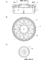
図2(A)は、図1に示す真空槽を構成する基板ステージ、基板ステージカバー、ガス排気経路及び防着板の配置関係を示す上面図であり、図2(B)はその断面図である。図2(A)及び(B)に示すように、基板ステージ4の外周には基板ステージカバー5が設けられ、その外周には、ガス排気経路7及び防着板6が設けられ、防着板と基板ステージとで構成されるガス排気経路7は、その大きさ(幅)がrとなるように構成されている。また、図2(B)に示すように、ガス排気経路の鉛直方向の長さがLとなるように構成されている。
2A is a top view showing the arrangement relationship of the substrate stage, the substrate stage cover, the gas exhaust path, and the deposition preventing plate constituting the vacuum chamber shown in FIG. 1, and FIG. 2B is a sectional view thereof. is there. As shown in FIGS. 2A and 2B, a
成膜ガス導入口の1次側には、図3に示すようなガス流量を制御できるガス源(原料ガス源、反応ガス源、不活性ガス源等)が接続されており、これらのガス源は、集積されて、1つのガス源から複数のガスを出すことができるように構成されている。
図4に上記集積されたガス源の例を示す。ガス源A、ガス源Bは、それぞれの必要に応じたラインに接続されている。すなわち、ガス源A及びBは、それぞれ、バルブ、マスフローコントローラ(MFC1、MFC2、MFC3)を介して、反応ガスライン及び不活性ガスラインに接続されている。さらに、ガス源BのラインにはベントVを介してベントガスラインが接続されており、このベントVはスローベントVでもよい。
A gas source (a raw material gas source, a reactive gas source, an inert gas source, etc.) capable of controlling the gas flow rate as shown in FIG. 3 is connected to the primary side of the film forming gas introduction port. Are configured so that a plurality of gases can be discharged from one gas source.
FIG. 4 shows an example of the integrated gas source. The gas source A and the gas source B are connected to lines according to their respective needs. That is, the gas sources A and B are connected to the reaction gas line and the inert gas line via valves and mass flow controllers (MFC1, MFC2, and MFC3), respectively. Further, a vent gas line is connected to the line of the gas source B via a vent V, and the vent V may be a slow vent V.
本発明においては、ガス源(図4)と成膜ガス導入口(図1)との間に図5に示すガス経路システムが設置されている。このシステムは、成膜プロセスを実施する際に、気化システムにより(液体)原料を気化して原料ガスとする原料ガス源と、プロセスに必要な反応ガス(不活性ガスと反応ガスとがプロセスに適した割合で混合されたガス。以後、これを「反応ガス」と略称する。)を供給できるガス源Aとから、それぞれのガスを混合器内へ供給し、そこで均一に混合するように構成されている。この混合器は、原料ガスと反応ガスとが対向して導入され、攪拌・拡散をへて均一に混合され、成膜ガスを得ることができるような構造となっている(特願平13−369279号)。この成膜ガスは、バルブV1の開放により成膜ガス導入口を経て図1の反応槽1内へ導入され、シャワーヘッド3を経て基板上に達する。不活性反応ガスは、ガス源BからバルブV6の開放により真空槽1の上蓋2の外周の開口部8から槽内へ導入される。同様に、真空槽内ベントの場合は、スローベントVのようなベントVとバルブV5とを開放することにより、成膜ガス導入口からシャワーヘッド3を介して槽内にベントガスを導入する。なお、図5中の熱交換器から1次側のガス経路(混合器も含む)は全て、室温〜250℃までの間で温度制御が可能となるように、ヒータ等の加熱手段や熱交換器のような温度制御手段を備えている。また、原料ガス源から出る全ての配管も、同様に、室温〜250℃まで温度制御が可能となるような同様の温度制御手段を備えている。
In the present invention, the gas path system shown in FIG. 5 is installed between the gas source (FIG. 4) and the film forming gas inlet (FIG. 1). In this system, when a film forming process is performed, a raw material gas source that vaporizes (liquid) raw material by a vaporization system to form a raw material gas and a reactive gas (inert gas and reactive gas) necessary for the process. A gas mixed at an appropriate ratio (hereinafter, abbreviated as “reactive gas”) is supplied from a gas source A to which the respective gases are supplied into the mixer, where they are mixed uniformly. Has been. This mixer has a structure in which a raw material gas and a reaction gas are introduced to face each other, and are uniformly mixed by stirring and diffusing to obtain a film forming gas (Japanese Patent Application No. 13-1990). 369279). This film forming gas is introduced into the
次に、図5に示すガス経路の動作について詳細に説明する。混合器は、バルブV3が設けられている配管により気化システムに接続されると共に、バルブV5及び熱交換器、次いでマスフローコントローラ(図示せず)を介してそれぞれガス源(例えば、反応ガス源、不活性ガス源)にも連結されている。混合器内で均一に混合された成膜ガスは、バルブV1が設けられている配管を経て成膜ガス導入口へと搬送され、真空槽内の基板ステージ上に載置された成膜対象物である基板の表面に供給される。この反応ガス源には、反応ガス源以外にキャリアガス等の不活性ガス(例えば、N2等)の供給系も接続されており、各供給系は、弁要素の調節によって、反応ガスやキャリアガスをガス源からマスフローコントローラー、熱交換器を経て、混合器へと配管により搬送するように構成されている。反応ガスには、目的とする膜を製造するための原料ガスに合わせたガス、例えば、還元反応の際はH2等、窒化反応の際はNH3等、酸化反応の際はO2等がある。原料ガスは、有機金属化合物等を有機溶媒に溶解した原料液を気化して得たガスである。 Next, the operation of the gas path shown in FIG. 5 will be described in detail. The mixer is connected to the vaporization system by a pipe provided with a valve V3, and is connected to a gas source (for example, a reactive gas source, a non-reactor) via a valve V5, a heat exchanger, and then a mass flow controller (not shown). It is also connected to an active gas source. The film-forming gas uniformly mixed in the mixer is transferred to the film-forming gas inlet through the pipe provided with the valve V1, and is formed on the substrate stage in the vacuum chamber. Is supplied to the surface of the substrate. In addition to the reaction gas source, an inert gas (for example, N 2 ) supply system is connected to the reaction gas source, and each supply system is controlled by adjusting a valve element. The gas is transported from the gas source to the mixer through a mass flow controller and a heat exchanger. Examples of the reaction gas include a gas suitable for a raw material gas for producing a target film, for example, H 2 in the reduction reaction, NH 3 in the nitridation reaction, O 2 in the oxidation reaction, and the like. is there. The source gas is a gas obtained by vaporizing a source solution obtained by dissolving an organometallic compound or the like in an organic solvent.
混合器では、反応ガス源から供給される適度に加熱された反応ガスと、気化システムにより生じ、液化/析出/成膜しない温度に保たれた配管を経て送られる原料ガスとが導入・混合され、成膜ガス(反応ガス+原料ガス等)が得られる。この原料ガスは、1種類の又は複数の種類のガスが混じったガスである。かくして得られた成膜ガスは、配管を経て真空槽内に導入される。 In the mixer, the appropriately heated reaction gas supplied from the reaction gas source and the raw material gas that is generated by the vaporization system and sent through a pipe maintained at a temperature at which no liquefaction / deposition / film formation is introduced and mixed are introduced and mixed. A film forming gas (reaction gas + raw material gas, etc.) is obtained. This source gas is a gas in which one kind or a plurality of kinds of gases are mixed. The film forming gas thus obtained is introduced into the vacuum chamber through a pipe.
この気化システムと混合器との間の配管及び混合器と成膜ガス導入口との間の配管はVCR継手で接続されていてもよく、一部の配管各継手のVCRガスケットは、ただのリングではなく穴のところがパーティクル捕獲器となっているVCR型パーティクル捕獲器であってもよい。このVCR型パーティクル捕獲器のある継手部は、原料ガスが液化/析出しない温度よりも高く設定・保持され、かつ、反応に必要な特定の気化した原料元素を付着・捕獲しないようにすることが望ましい。 The pipe between the vaporization system and the mixer and the pipe between the mixer and the film forming gas inlet may be connected by a VCR joint, and the VCR gasket of some of the pipe joints is a simple ring. Instead, it may be a VCR type particle trap where the hole is a particle trap. The joint with this VCR type particle trap is set and maintained at a temperature higher than the temperature at which the source gas is not liquefied / deposited, and does not attach or trap the specific vaporized source elements necessary for the reaction. desirable.
混合器と真空槽との間の成膜ガスラインには、成膜ガスの切替えを行うバルブ(V1及びV2)が混合器5の2次側に設けられてある。バルブV1及びV2の下流側は、それぞれ、真空槽及び排気システムに接続されている。成膜時は、バルブV1を開けてバルブV2を閉じ、成膜終了後は、バルブV2を開けてバルブV1を閉じる。原料ガスや反応ガスを混合器に導入する初期の数瞬の間は、混合が均一でなく安定しないので、バルブV1を閉じてバルブV2を開け、排気システムに原料ガスと反応ガスとの混合ガスを流すようにし、混合が安定した後に、バルブV2を閉じてバルブV1を開け、シャワーヘッドを介して反応空間に成膜ガスを導入できるようにする。また、成膜終了時には、瞬時の間バルブV2を開けてバルブV1を閉じ、混合器内の反応に使用されなかった余剰の成膜ガスを排気システムに流すことにより、反応空間への成膜ガスの導入を瞬時に止め、反応空間内に導入されることがないように構成する。
Valves (V1 and V2) for switching the film forming gas are provided on the secondary side of the
気化システムは、図示していないが、原料供給部と気化部とから構成されている。この気化システムは、加圧ガス(例えば、Heガス等の不活性ガス)により液体・固体原料を有機溶媒に溶解した原料液を加圧・搬送し、圧送された原料液のそれぞれの流量を各液体流量制御器で制御して、気化部に運ぶように構成されている。気化部は、流量の制御された原料液を効率よく気化させ、気化して得られた原料ガスを混合器へ供給することができるように構成されている。この気化部では、液体原料が1種の場合は単液を、液体原料が複数の場合は複数の原料液を混合して気化させることができる。原料液を気化させる際は、原料液の液滴を気化させるだけでなく、液滴にガスを当てたり、物理的な振動を与えたり又は超音波を当てたりして、気化部の壁面に設けたノズルを介して更に細かい液粒として気化部内に導入して気化させ、気化効率を上げることが好ましい。気化部の内部には、液滴又は液粒が、効率良く気化すべき箇所で極力気化することができるように、かつ、パーティクル捕獲器による液粒気化負荷の軽減のために、Al等の熱伝導の良い材料で作製された気化部材を配置することが好ましい。また、気化部の内部には、原料液が気化する際に発生する残渣を元とするパーティクルを気化部外に出さないためや、少量流れ来る液滴が気化器外に真空により吸い込まれることなく気化できるようにするために、パーティクル捕獲器を設けてもよい。この気化部材とパーティクル捕獲器においては、これらに接触した液滴、細かい液粒が確実に気化できるように、かつ、反応に必要な特定の気化した原料元素を付着・捕獲しないように、適切な温度に気化条件が保たれていることが好ましい。なお、この気化システムは、原料用の溶媒を有し、その流量を流量制御器で制御して気化部へ導入し、気化部で気化させ、この溶媒ガスを作ることが可能なように構成されていてもよい。 Although not shown, the vaporization system includes a raw material supply unit and a vaporization unit. This vaporization system pressurizes and conveys a raw material liquid obtained by dissolving a liquid / solid raw material in an organic solvent with a pressurized gas (for example, an inert gas such as He gas), and sets the flow rate of each of the pumped raw material liquids. It is configured to be controlled by a liquid flow rate controller and carried to the vaporization section. The vaporization unit is configured to efficiently vaporize the raw material liquid whose flow rate is controlled and supply the raw material gas obtained by vaporization to the mixer. In this vaporization section, when there is only one liquid raw material, a single liquid can be mixed, and when there are a plurality of liquid raw materials, a plurality of raw material liquids can be mixed and vaporized. When vaporizing the raw material liquid, not only vaporize the liquid droplets of the raw material liquid, but also apply gas to the liquid droplets, apply physical vibrations, or apply ultrasonic waves to the vaporization part wall surface. It is preferable to introduce vaporization into the vaporization part as finer liquid particles through the nozzle and vaporize it to increase the vaporization efficiency. Inside the vaporization section, heat or liquid such as Al is used so that droplets or liquid particles can be vaporized as much as possible at the place where vaporization should be efficiently performed, and in order to reduce the liquid vaporization load by the particle trap. It is preferable to arrange a vaporizing member made of a material having good conductivity. In addition, inside the vaporization unit, particles based on the residue generated when the raw material liquid is vaporized are not discharged out of the vaporization unit, and a small amount of liquid droplets are not sucked out of the vaporizer by vacuum. In order to be able to vaporize, a particle trap may be provided. In this vaporization member and particle trap, appropriate droplets and fine liquid particles that are in contact with these vaporizers can be properly vaporized, and appropriate vaporizer elements that are necessary for the reaction are not attached or captured. It is preferable that vaporization conditions are maintained at the temperature. This vaporization system has a raw material solvent, and is configured so that the flow rate is controlled by a flow rate controller, introduced into the vaporization unit, and vaporized by the vaporization unit to produce the solvent gas. It may be.
なお、成膜対象物である加熱された基板上にシャワーヘッド3を介して成膜ガスが導入されて、反応が開始されるが、反応に使用されなかった余剰の成膜ガスや、反応により生じた副生成物ガスや、反応物ガスは排気システムにより排気される。真空槽1の上蓋2内に組み込まれたシャワーヘッド3には、成膜ガス中に存在するパーティクルを捕獲するためのフィルターとしてのパーティクル捕獲器を配設してもよい。シャワーヘッド3は、適度に加熱され、導入ガスが液化/析出/成膜しない温度に保たれている。また、パーティクル捕獲器は、反応に必要な特定の気化した原料元素を付着・捕獲しない温度に適切に調整されていることが望ましい。
上記排気システムと真空槽との間に設けられた圧力調整バルブにより、様々な成膜圧力条件に容易に対応することが出来る。
A film forming gas is introduced onto the heated substrate, which is a film forming target, via the
Various film forming pressure conditions can be easily accommodated by the pressure adjusting valve provided between the exhaust system and the vacuum chamber.
本発明の薄膜製造装置では、シャワープレート表面−基板間距離は、固定され、成膜時、搬送時とも同じ距離となるように構成されるが、基板ステージを組み上げる段階でスペーサーを選択することにより、任意の距離、例えば10mm、25mm、40mmの3種から選択可能な構造とすることもできる。 In the thin film manufacturing apparatus of the present invention, the distance between the surface of the shower plate and the substrate is fixed, and is configured to be the same distance during film formation and transport, but by selecting a spacer at the stage of assembling the substrate stage. Further, a structure that can be selected from three types of arbitrary distances, for example, 10 mm, 25 mm, and 40 mm, can be used.
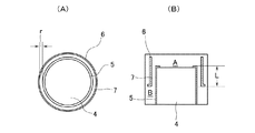
次に、本発明の薄膜製造装置における、真空槽上蓋及びシャワープレートに付いて図6を参照して説明する。図6中、図1と同じ構成要素は同じ参照番号を付してある。図6(A)は真空槽1の上方部分の断面図を示し、図6(B)は真空槽の上方部分を所定の位置で切った全体の上面図を示し、そして図6(C)は真空槽の上方部分を所定の位置で切った中心部の上面図を示す。
Next, the vacuum tank upper lid and the shower plate in the thin film manufacturing apparatus of the present invention will be described with reference to FIG. In FIG. 6, the same components as those in FIG. 1 are denoted by the same reference numerals. 6A shows a cross-sectional view of the upper portion of the
図6に示したように、ガスが広がる部分13を含むシャワーヘッド構造を上蓋2に組み入れて、上蓋2とシャワーヘッド3とを一体化構造としてもよい。また、シャワープレート3の大きさは、真空槽1の天井部の面積と同程度の大きさに設計されている。このような構造を取ることにより、図6で示すように、シャワープレート3が熱交換する領域(接触面積)が大きく確保され、熱交換を効率良く行なえることになる。
シャワープレート3の面積は、図1に示すようなシャワープレート3と基板ステージ4と防着板5とで囲まれた反応空間Aの天井面積よりも大きくなるように構成してある。反応空間(すなわち、シャワープレートが輻射を受ける面積)は小さくしつつ、シャワープレート3の熱交換のための面積は十分に確保されている構造になっている。
As shown in FIG. 6, a shower head structure including a
The area of the
この上蓋2は、SUS製であり、図6に示すように、油インから油アウトの油循環経路14により温度制御が行なえるように構成されている。油循環経路14は、上蓋内部を広範囲に座刳って構成されており、また、シャワープレート3を止めるネジ穴3aは油が満たされる範囲内部で島状に存在し、油循環経路が広くなっているため、上蓋2の温度を均一にできるとともに温度制御性も良くなっている。また、油循環経路14の大部分は、上蓋2に組み込まれたシャワープレート3の表面と接触して配置され、熱交換効率が向上できるように構成されている。従って、特に、成膜時の基板温度が高温で、シャワープレート−基板間距離が近く、シャワープレート3が強烈な輻射により加熱される環境においても、対応可能な優れた熱交換効率を実現できる構造となっている。この循環経路で用いる媒体は、油でなくとも、同じ作用を有する公知の温媒体等の媒体であれば特に制限されない。
The
このシャワープレート3は、横から見て凹の形をしており、ガス通過部分はシャワー穴のコンダクタンスを最適にする厚さ(一般的には、約5mm程度)が好ましい。
シャワープレート3と上蓋2の熱交換部分はシャワープレート熱交換部分の温度均一性を上げる目的で厚く(例えば、約10mm程度)設計されており、熱交換する部分のシャワープレートの熱をシャワープレート全体に広げた後に熱交換することで熱交換効率を上げている。
The
The heat exchange part of the
以下、MOCVD法によりPZT膜を製造するための標準の成膜条件を挙げ、本発明の装置を用いてこの条件で成膜を行った。
(原料) (濃度) (設定流量)
Pb(dpm)2/THF 0.3mol/L 1.16mL/min
Zr(dmhd)4/THF 0.3mol/L 0.57mL/min
Ti(iPrO)2(dpm)2/THF 0.3mol/L 0.65mL/min
N2(キャリアガス) 500sccm
(反応ガス)
O2 2500sccm
(ガスヘッド周り不活性ガス)
N2 1500sccm
成膜圧力:圧力調整バルブにより常に5Torr一定に調整。
基板温度:580℃
シャワープレート−基板間距離:30mm
Hereinafter, standard film formation conditions for producing a PZT film by the MOCVD method are listed, and film formation was performed under these conditions using the apparatus of the present invention.
(Raw material) (Concentration) (Set flow rate)
Pb (dpm) 2 / THF 0.3mol / L 1.16mL / min
Zr (dmhd) 4 / THF 0.3mol / L 0.57mL / min
Ti (iPrO) 2 (dpm) 2 / THF 0.3mol / L 0.65mL / min
N 2 (carrier gas) 500sccm
(Reactive gas)
O 2 2500sccm
(Inert gas around the gas head)
N 2 1500sccm
Film forming pressure: always adjusted to 5 Torr constant by the pressure adjusting valve.
Substrate temperature: 580 ° C
Shower plate-substrate distance: 30 mm
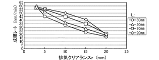
図1に示す薄膜製造装置を用い、基板ステージ4上に載置した8インチ電極基板上に、ガス排気経路7の大きさ、すなわち排気クリアランス(r:3〜20mm)と鉛直方向の長さ(L:30、50、70、90mm)とを変化させて、上記成膜条件でPZT膜を製造した。その結果得られた膜の膜厚分布(%)を排気クリアランスとの関係で図7に示す。図7から明らかなように、排気経路の大きさ(r)=3mm以上、鉛直方向の長さ(L)70mm以上とすることで、面内3%以下の良好な膜厚分布を安定して得ることができる。
Using the thin film manufacturing apparatus shown in FIG. 1, on the 8-inch electrode substrate placed on the
また、8インチ電極基板上に、ガス排気経路すなわち排気クリアランスの大きさ(r)と鉛直方向の長さ(L)とを変化させて、上記成膜条件でPZT膜を製造した。この際の排気クリアランスと成膜レートとの関係を図8に示す。条件により膜厚分布に差が出るため基板中心の成膜レートを求めて比較してある。量産装置においては、スループットを考慮すると成膜時間は3min以下が望ましい。例えば、目標膜厚100nmとした場合、約35nm/min以上の成膜レートが必要となる。図8から明らかなように、この成膜レートを満足する条件は、鉛直方向の長さ(L)=70mm以上では排気経路の大きさ(r)=3〜15mmである。 Further, a PZT film was manufactured on the 8-inch electrode substrate under the above film forming conditions by changing the gas exhaust path, that is, the size (r) of the exhaust clearance and the vertical length (L). FIG. 8 shows the relationship between the exhaust clearance and the film formation rate at this time. Since the film thickness distribution varies depending on the conditions, the film formation rate at the center of the substrate is obtained and compared. In a mass production apparatus, the film formation time is desirably 3 min or less in consideration of the throughput. For example, when the target film thickness is 100 nm, a film forming rate of about 35 nm / min or more is required. As is apparent from FIG. 8, the condition for satisfying this film formation rate is that the size (r) of the exhaust path is 3 to 15 mm when the length in the vertical direction (L) is 70 mm or more.
なお、図6におけるガスが広がる空間(反応空間)やシャワープレートの大きさや真空槽の天井部の大きさの各部の寸法は、R1=200mm、R2=370mm、R3=390mmに設計されている。シャワープレート3は、上蓋2の外周不活性ガス噴出口を除くほぼ全ての面積を熱交換面積として活用できる直径(R2)としている。これにより、上蓋とシャワープレートの熱交換面積(φR2−φR1)はガス通過部(φR1=シャワープレートと上蓋の熱交換無し)の約2.4倍が確保されている。
6 are designed such that R1 = 200 mm, R2 = 370 mm, and R3 = 390 mm, the dimensions of the space (reaction space) in which the gas spreads, the size of the shower plate, and the size of the ceiling of the vacuum chamber. The
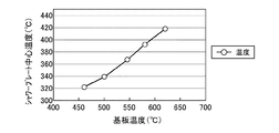
また、図1に示す装置構成において、シャワープレート−基板間距離40mmで、上蓋の温度制御を行なわずに基板温度を変更した時のシャワープレートの中心温度変化を確認した。その結果を図9に示す。反応空間は不活性ガス雰囲気5Torrに制御されている。標準とする上記成膜条件に示した材料のうち原料は、200℃以下で析出し、250℃以上で分解が起るため、原料ガスが接触する箇所は200℃〜250℃の範囲に制御する必要がある。乱流・対流・熱対流を押える図1に示す装置構造においては、図9に示すように、基板と近距離で対向するシャワープレートの温度は上昇してしまうため、シャワープレートの温度制御は必須の項目である。 Further, in the apparatus configuration shown in FIG. 1, a change in the center temperature of the shower plate was confirmed when the substrate temperature was changed without controlling the temperature of the upper lid at a shower plate-substrate distance of 40 mm. The result is shown in FIG. The reaction space is controlled to an inert gas atmosphere of 5 Torr. Among the materials shown in the standard film formation conditions, the raw material is deposited at 200 ° C. or lower and decomposes at 250 ° C. or higher. Therefore, the location where the raw material gas contacts is controlled within the range of 200 ° C. to 250 ° C. There is a need. In the apparatus structure shown in FIG. 1 that suppresses turbulent flow, convection, and thermal convection, as shown in FIG. 9, the temperature of the shower plate facing the substrate at a short distance increases, so the temperature control of the shower plate is essential. It is an item.
また、図1に示す装置構造において、不活性ガス雰囲気、圧力5Torr、基板温度580℃、上蓋の温度制御を行なわない条件で、シャワープレート−基板間距離を変更した時のシャワープレート中心温度変化を確認した。その結果を図10に示す。図10から明らかなように、シャワープレート−基板間距離のシャワープレート温度への影響は基板温度よりも非常に鈍くはあるが、シャワープレート−基板間距離を短くすればシャワープレート温度が上昇する(40mm→10mmの変化で約16℃温度上昇)。 Further, in the apparatus structure shown in FIG. 1, the change in shower plate center temperature when the distance between the shower plate and the substrate is changed under the condition that the inert gas atmosphere, the pressure is 5 Torr, the substrate temperature is 580 ° C., and the temperature of the upper lid is not controlled. confirmed. The result is shown in FIG. As apparent from FIG. 10, the influence of the shower plate-substrate distance on the shower plate temperature is much slower than the substrate temperature. However, if the shower plate-substrate distance is shortened, the shower plate temperature increases ( The temperature rises by about 16 ° C. with a change from 40 mm to 10 mm).
次に、図6に示す構造を有する真空槽上蓋に215℃の油を5L/min以上で循環させた。不活性ガス雰囲気、圧力5Torr、基板温度580℃、シャワープレート−基板間距離40mmの時、シャワープレート中心温度は232℃になり、油循環前に比べ約160℃下げることができた。この時のシャワープレート中心から半径方向の温度分布を図11に示す。図11から明らかなように、シャワープレートの温度分布は±10℃の範囲に入っており、また、シャワープレート温度が最も成膜に対し影響を与える成膜ガスが通過する範囲φ200mm(中心からの半径100mm)の温度分布は、約±5℃と良好であった。さらに、油循環温度は215℃であり、上蓋温度は210℃以上に維持され、上蓋の成膜ガスが導入される空間で原料が析出することが無かった。 Next, oil at 215 ° C. was circulated at a rate of 5 L / min or more through the upper lid of the vacuum chamber having the structure shown in FIG. When the inert gas atmosphere, the pressure was 5 Torr, the substrate temperature was 580 ° C., and the distance between the shower plate and the substrate was 40 mm, the shower plate center temperature was 232 ° C., which was about 160 ° C. lower than before the oil circulation. FIG. 11 shows the temperature distribution in the radial direction from the center of the shower plate at this time. As is apparent from FIG. 11, the temperature distribution of the shower plate is in the range of ± 10 ° C., and the range in which the shower plate temperature passes through the film forming gas that most affects the film formation is φ200 mm (from the center). The temperature distribution with a radius of 100 mm was as good as about ± 5 ° C. Furthermore, the oil circulation temperature was 215 ° C., the upper lid temperature was maintained at 210 ° C. or higher, and no raw material was deposited in the space where the film formation gas for the upper lid was introduced.
また、図6の構造においてシャワープレート−基板間距離を10mmとした場合、図10に示すように、シャワープレート表面の最高温部(シャワープレート中心点)の温度上昇は最大でも16.2℃以下であった。従って、シャワープレート−基板間距離10mmにおいても、シャワープレートは200〜250℃の温度範囲に維持させることができる。さらに、循環する油温度を選択することによってシャワープレートを最適温度に調整することもできる。 Further, in the structure of FIG. 6, when the distance between the shower plate and the substrate is 10 mm, as shown in FIG. 10, the temperature rise of the highest temperature portion (shower plate center point) on the surface of the shower plate is 16.2 ° C. or less at the maximum. Met. Therefore, even when the distance between the shower plate and the substrate is 10 mm, the shower plate can be maintained in the temperature range of 200 to 250 ° C. Furthermore, the shower plate can be adjusted to the optimum temperature by selecting the circulating oil temperature.
図6に示すシャワープレート固定ネジ(M6×24本)3aの締め付けトルクは各5N・mとして、ネジ1本の軸方向の力Wは次式で与えられる。ここで、F:締め付ける力、T:締め付けトルク、d:有効径、l:ネジリード、μ:摩擦係数である。
F = 2T/D
F = W(l + μπd)/(πd − μl)
W×24(ネジ本数)の値をシャワープレートが熱交換する面積で割ると約28.4kgf/cm2となる。従って、シャワープレートを28.4kgf/cm2以上の力で上蓋の熱交換面に押し付けないと図11に示すような冷却効果は望めない。
The tightening torque of the shower plate fixing screw (M6 × 24 pieces) 3a shown in FIG. 6 is 5 N · m, and the axial force W of one screw is given by the following equation. Here, F: tightening force, T: tightening torque, d: effective diameter, l: screw lead, μ: friction coefficient.
F = 2T / D
F = W (l + μπd) / (πd−μl)
Dividing the value of W × 24 (number of screws) by the area where the shower plate exchanges heat gives about 28.4 kgf / cm 2 . Therefore, the cooling effect as shown in FIG. 11 cannot be expected unless the shower plate is pressed against the heat exchange surface of the upper lid with a force of 28.4 kgf / cm 2 or more.
本発明の装置(図1〜6)を用いて成膜を行なうと、上述(図7、8)のように、面内膜厚分布が良好な成膜を再現性良く行なえる。 When film formation is performed using the apparatus of the present invention (FIGS. 1 to 6), film formation with a good in-plane film thickness distribution can be performed with good reproducibility as described above (FIGS. 7 and 8).
図9〜11に示す結果を踏まえて付け加えると、図1の装置構成においては、図6に示す真空槽上蓋とシャワーヘッドとが一体的となった構造を用いないと、すなわち、真空槽上蓋にシャワーヘッド構造を組み込み、シャワープレートの表面積がほぼ真空槽天井の面積と同程度となるようにして、最大面積を確保し、シャワープレートの熱交換面積を成膜ガス通過部の2.4倍以上とし、上蓋内の油循環経路をシャワープレートを固定する面の近傍にできるだけ配置して熱交換効率を上げ、シャワープレートを上蓋に固定するネジ穴を島状に加工して油循環経路を最大限に取り、熱交換効率を上げる対策を用いないと、シャワーヘッド表面−基板間距離が40mm以下、基板温度580℃以上という環境では、シャワープレート表面温度を250℃以下に下げることはできないと言える。 In addition, based on the results shown in FIGS. 9 to 11, in the apparatus configuration of FIG. 1, the structure in which the vacuum tank upper cover and the shower head shown in FIG. 6 are integrated is not used. A shower head structure is incorporated, the surface area of the shower plate is approximately the same as the area of the vacuum chamber ceiling, ensuring the maximum area, and the heat exchange area of the shower plate is 2.4 times or more that of the film forming gas passage. The oil circulation path in the upper lid is placed as close as possible to the surface where the shower plate is fixed to increase the heat exchange efficiency, and the screw hole that fixes the shower plate to the upper lid is processed into an island shape to maximize the oil circulation path. Therefore, if the measure for increasing the heat exchange efficiency is not used, the shower plate surface temperature is 25 in an environment where the distance between the shower head surface and the substrate is 40 mm or less and the substrate temperature is 580 ° C. or more. It can be said that it cannot be lowered below 0 ° C.
図1の構造において、シャワープレート−基板間距離が40mmの時、反応空間Aは3.6Lであり、下部空間Bは4.7Lであった。基板ステージの昇降機構を無くし、基板ステージを固定したことで、同心円の等方排気口の2次側の下部空間として必要とされる容積は反応空間の約1.3倍程度となり、装置の小型化が実現でき、かつ、駆動系動作のための遊びを排除したため、上述のように排気経路の大きさ(r)=3mmにおいて(鉛直距離:L=70mm以上)、面内3%以下の良好な膜厚分布を安定して再現性を良く得ることができた。 In the structure of FIG. 1, when the distance between the shower plate and the substrate was 40 mm, the reaction space A was 3.6 L and the lower space B was 4.7 L. By eliminating the substrate stage lifting mechanism and fixing the substrate stage, the volume required as the lower space on the secondary side of the concentric isotropic exhaust port is about 1.3 times the reaction space, making the device compact. As described above, when the size of the exhaust path (r) = 3 mm (vertical distance: L = 70 mm or more), the in-plane quality is 3% or less. The film thickness distribution was stable and good reproducibility was obtained.
図1の装置構造では、上蓋外周の開口部8から真空槽1内に供給される不活性ガスは、まず防着板6の外側へ導入され、防着板外側と真空槽内壁で囲まれた防着板外周空間を満たした後に、噴出口9から反応空間Aに進入する構造となっているので、成膜ガスが反応空間Aから防着板外周空間に進入することを防ぐことができ、その結果、真空槽内壁で成膜が起らず、真空槽のクリーニングが不要となった。
In the apparatus structure of FIG. 1, the inert gas supplied into the
付け加えると、PZT、SBT、BST等の高・強誘電体膜を形成する場合、これらの膜が結晶化してしまうと、プラズマクリーニングやケミカルドライクリーニングではその膜を除去することは非常に困難であるので、一般的には硝酸等のウエットケミカルクリーニングが用いられる。従って、防着板等の取り外し可能な部品以外に膜が付いた場合には、“作業員が硝酸でこすって除去する”等、量産現場では受け入れられ難い作業が生じてしまう。本装置は、これらの危険な作業が発生しない構造を有している。 In addition, when forming high-ferroelectric films such as PZT, SBT, and BST, if these films crystallize, it is very difficult to remove the films by plasma cleaning or chemical dry cleaning. Therefore, in general, wet chemical cleaning such as nitric acid is used. Therefore, when a film is attached to a part other than a removable part such as an adhesion prevention plate, an operation that is unacceptable at a mass production site, such as “an operator rubs away with nitric acid” occurs. This apparatus has a structure that does not cause these dangerous operations.
本実施例の基板ステージを模式的に図12(A)及び(B)に示す。図12(A)は真空槽上蓋とシャワープレートとの配置を示す概略断面図、(B)はその上面図である。図12において、図1と同じ構成要素は同じ参照番号を付してある。
熱源15の上にSiC製のサセプター16が配置され、このSiCサセプター16の上に基板Sと基板ステージ部材17が配置されている。基板ステージ部材17はSi3N4製である。基板Sは基板ステージ部材17により位置決めできるようになっている。シャワープレートと対向する基板ステージは平坦であり、基板が唯一平面より凸になっている。このように基板のみが唯一凸となり、後は平坦な基板ステージとすることにより、基板近傍で乱流・対流を発生させずに、再現性良く安定して成膜できる構造としている。
FIGS. 12A and 12B schematically show the substrate stage of this example. FIG. 12A is a schematic cross-sectional view showing the arrangement of the vacuum tank upper lid and the shower plate, and FIG. 12B is a top view thereof. 12, the same components as those in FIG. 1 are denoted by the same reference numerals.
A
このSiC製サセプター16は熱伝導率が良好で、熱源15からの熱を均一に基板Sに伝えることができる。さらに、SiCは酸化による時経変化が起こり難いため、このような構成は、反応ガスに酸素を用い、かつ、基板高温が500℃以上の高温プロセスの場合に適している。
SiCサセプター16は熱源15の直上にあるため、基板Sよりも高温に曝されるので、成膜ガスに触れると速い速度で表面に膜が付く。このため、本発明では、SiCサセプター16の表面が成膜ガスに触れる面積を最少にするため、SiCサセプターをカバーする基板ステージ部材である基板ステージカバー5を配置することが好ましい。
This SiC susceptor 16 has good thermal conductivity, and can transmit heat from the
Since the
上記基板ステージ部材17は、サセプターと同心円で中央部分が空いており、中央部分の直径は基板直径よりも僅かに大きく、基板Sの位置決めが行なえる構造となっている。基板ステージ部材17は、熱伝導率が低くかつ熱衝撃特性が良好なSi3N4製であり、SiCサセプター16の熱を奪い、SiCサセプターの均熱を崩す作用を最小限にとどめ、かつ、熱源15の急激な加熱サイクル(基板を室温→成膜温度まで短時間で昇温するサイクル)においても破損しない様考慮されている。このように、基板を均一に加熱するために熱源上に設けるSiC製サセプターと、熱伝導率が低く、熱サイクル及び酸素ガスに対する耐性の良好なSi3N4部材からなる基板ステージ部材とを用いることで、部品破損頻度が少なく、パーティクルの発生が少ない基板ステージを持つ薄膜製造装置を構成することができる。
The
なお、本装置の開発過程で基板ステージ部材に石英を用いたが、SiCサセプターとの接触部が高温となり、成膜ガスに含まれるPb、酸素と反応し、石英中へのPb拡散現象や石英のO2抜け、透失現象が発生し、特性が変化してしまった。また、部品の硝酸洗浄においても侵食が顕著に見られた。
また、本装置の開発過程で基板ステージ部材にAl2O3を用いたが、SiCサセプターとの接触部に急激な熱サイクルによるマイクロクラックが発生し、破損した。また、マイクロクラックがパーティクルの発生源となった。
Although quartz was used for the substrate stage member in the development process of this apparatus, the contact portion with the SiC susceptor becomes high temperature, reacts with Pb and oxygen contained in the film forming gas, and Pb diffusion phenomenon into quartz or quartz O 2 loss and loss-of-sight phenomenon occurred, and the characteristics changed. Also, erosion was noticeable in the nitric acid cleaning of parts.
In addition, Al 2 O 3 was used as the substrate stage member in the development process of this apparatus, but microcracks due to a rapid thermal cycle occurred at the contact portion with the SiC susceptor, and the substrate stage member was damaged. Moreover, the micro crack became a generation source of particles.
上記Si3N4製の基板ステージ部材は、量産装置においては数1000枚/月の基板を処理することが要求されること、また、反応空間を構成する部材が定期的なメンテナンスで酸洗浄を繰り返す耐性が要求されることを考慮して選定されている。
基板ステージの構成において、唯一基板のみが凸となり、後は平坦な基板ステージとすることにより、基板近傍で乱流・対流を発生させずに、再現性良く安定して成膜できる構造としている。
The substrate stage member made of Si 3 N 4 is required to process several thousand substrates / month in a mass production apparatus, and the members constituting the reaction space are subjected to acid cleaning by regular maintenance. It is selected taking into consideration that repeated resistance is required.
In the structure of the substrate stage, only the substrate is convex, and the flat substrate stage is used thereafter, so that a film can be formed stably with good reproducibility without generating turbulence and convection in the vicinity of the substrate.
本発明によれば、以上の他に、凸凹の無い円筒形の真空槽内壁と円筒形の基板ステージの外側とによりガス排気経路を構成し、又は円筒形以外の形の基板ステージ部材を用いた場合には、結果的には円筒形の基板ステージの役目を果すようにして、この基板ステージ部材と真空槽内壁とによりガス排気経路を構成する。ガス排気経路の隙間、長さを調整して、排気経路の2次側に反応空間の1.3倍以上の排気空間を構成することにより等方排気を実現し、良好な膜厚分布、成膜レートを得ることができる。 According to the present invention, in addition to the above, a gas exhaust path is configured by the cylindrical inner wall of the cylindrical vacuum chamber without unevenness and the outer side of the cylindrical substrate stage, or a substrate stage member having a shape other than the cylindrical shape is used. In this case, as a result, a gas exhaust path is constituted by the substrate stage member and the inner wall of the vacuum chamber so as to serve as a cylindrical substrate stage. By adjusting the gap and length of the gas exhaust path and forming an exhaust space at least 1.3 times the reaction space on the secondary side of the exhaust path, isotropic exhaust is realized, and a good film thickness distribution, A membrane rate can be obtained.
また、円筒形又はそれ以外の形の反応空間内を凸凹の無い円筒形の筒で仕切り、円筒形の反応空間とし、円筒形の筒と円筒形の基板ステージとによりガス排気経路を構成し、又は円筒形以外の形の基板ステージ部材を用い、これが結果的には円筒形の基板ステージの役目を果すようにして、この基板ステージと真空槽内壁とによりガス排気経路を構成し、ガス排気経路の隙間、長さを調整し、この排気経路の2次側に反応空間に対し1.3以上の排気空間を構成することにより等方排気を実現し、良好な膜厚分布、成膜レートを得ることができる。 In addition, a cylindrical or other shape reaction space is partitioned by a cylindrical tube having no irregularities to form a cylindrical reaction space, and a gas exhaust path is constituted by the cylindrical tube and the cylindrical substrate stage, Alternatively, a substrate stage member having a shape other than a cylindrical shape is used, and as a result, the substrate stage member serves as a cylindrical substrate stage, and a gas exhaust path is configured by the substrate stage and the inner wall of the vacuum chamber. The isotropic exhaust is realized by adjusting the gap and length of the gas and by constructing an exhaust space of 1.3 or more with respect to the reaction space on the secondary side of the exhaust path, and providing a good film thickness distribution and film formation rate. Obtainable.
また、真空槽上蓋にシャワーヘッド構造を組み込み、上蓋が真空槽の天井として最大の面積を持つことを利用して、温媒を循環する経路を上蓋内に最大限取り、また、上蓋にシャワープレートを固定できる構造とし、また、シャワープレートを真空槽天井とほぼ同じ面積とし、また、シャワープレートと上蓋との熱交換部分の面積をシャワープレートのガス通過面積の2.4倍以上とし、また、シャワープレートを上蓋に28.4kgf/cm2以上の力で押しつけることにより、シャワープレート−基板間距離が40mm以下であっても、シャワープレート表面温度分布を±10℃以下に制御できる構造とすることができる。上蓋及びシャワープレートが円盤以外の形状であっても同様の効果が得られる。 In addition, by incorporating a shower head structure in the upper lid of the vacuum chamber, and taking advantage of the fact that the upper lid has the largest area as the ceiling of the vacuum chamber, take the maximum route for circulating the heating medium in the upper lid, and the shower plate on the upper lid The shower plate has almost the same area as the ceiling of the vacuum chamber, and the area of the heat exchange part between the shower plate and the top lid is 2.4 times the gas passage area of the shower plate, By pressing the shower plate against the upper lid with a force of 28.4 kgf / cm 2 or more, the surface temperature distribution of the shower plate can be controlled to ± 10 ° C. or less even when the distance between the shower plate and the substrate is 40 mm or less. Can do. The same effect can be obtained even if the upper lid and the shower plate have a shape other than the disk.
また、ベントガスラインを、成膜ガスラインに限らず、シャワーヘッドにも接続することで、ベントの際のパーティクルの巻上げを防ぎ、真空槽内にパーティクルが四散するのを防ぐこともできる。
さらに、基板を均一に加熱するために熱源上に設けるSiC製サセプターと、熱伝導率が低く、熱サイクル及び酸素ガスに対する耐性の良好なSi3N4部材からなる基板ステージ部材とを用いることで、部品破損頻度が少なく、パーティクルの発生が少ない基板ステージを持つ薄膜製造装置を構成することができる。
Further, by connecting the vent gas line not only to the film forming gas line but also to the shower head, it is possible to prevent the particles from being rolled up during the venting and to prevent the particles from being scattered in the vacuum chamber.
Furthermore, by using a SiC susceptor provided on a heat source to uniformly heat the substrate, and a substrate stage member made of a Si 3 N 4 member having low thermal conductivity and good resistance to thermal cycling and oxygen gas. Thus, a thin film manufacturing apparatus having a substrate stage with a low frequency of component breakage and less particle generation can be configured.
さらにまた、上記の応用例を組み合わせることで、真空槽内、ひいては反応空間内の乱流・対流・熱対流を押さえる整流作用を最大限に引き出し、基板に生成する薄膜の膜質や膜厚分布を向上させ、より膜厚分布、膜組成分布、成膜レートが良好かつ安定し、成膜ダストが少なく、真空槽内部への成膜を軽減でき、連続成膜が安定して行なえる薄膜製造装置を確立することができる。 Furthermore, by combining the above application examples, the rectifying action that suppresses turbulence, convection, and thermal convection in the vacuum chamber and thus in the reaction space is maximized, and the film quality and film thickness distribution of the thin film generated on the substrate can be reduced. Thin film manufacturing equipment that can improve the film thickness distribution, film composition distribution, and film formation rate, improve and stabilize film formation, reduce film formation dust, reduce film formation inside the vacuum chamber, and achieve stable film formation. Can be established.
本発明は、上記したように、パーティクルの発生がほとんどなく又はあっても極めて少なく、膜質、膜性能が安定した薄膜を長期にわたって安定して成膜することのできる薄膜製造装置及び薄膜製造方法に関するものである。この装置及び方法は、電気・電子分野において、例えば金属酸化物膜等を製造する際に有効に利用できる。
この装置は、産業上、低ダスト、良好な再現性等が要求される量産装置として大いに威力を発揮する。また、特に熱エネルギーを利用したCVDプロセスにおいて大変威力を発揮する。
As described above, the present invention relates to a thin film manufacturing apparatus and a thin film manufacturing method capable of stably forming a thin film having a stable film quality and film performance over a long period with little or no generation of particles. Is. This apparatus and method can be used effectively when, for example, a metal oxide film or the like is manufactured in the electric / electronic field.
This apparatus is very effective as a mass production apparatus that requires low dust and good reproducibility in the industry. In addition, it is very effective especially in the CVD process using thermal energy.
1 真空槽 2 上蓋
3 シャワーヘッド 4 基板ステージ
5 基板ステージカバー 6 防着板
6a 防着板リフター 7 ガス排気通路
8 開口部 9 不活性ガス噴出口
13 ガスが広がる部分 14 油循環経路
16 サセプター 17 基板ステージ部材
A 反応空間 B 下部空間
r ガス排気経路の大きさ L ガス排気経路の鉛直方向長さ
DESCRIPTION OF
Claims (25)
Priority Applications (1)
| Application Number | Priority Date | Filing Date | Title |
|---|---|---|---|
| JP2009269841A JP2010056565A (en) | 2009-11-27 | 2009-11-27 | Apparatus for forming thin film |
Applications Claiming Priority (1)
| Application Number | Priority Date | Filing Date | Title |
|---|---|---|---|
| JP2009269841A JP2010056565A (en) | 2009-11-27 | 2009-11-27 | Apparatus for forming thin film |
Related Parent Applications (1)
| Application Number | Title | Priority Date | Filing Date |
|---|---|---|---|
| JP2003287760A Division JP4445226B2 (en) | 2003-08-06 | 2003-08-06 | Thin film manufacturing equipment |
Publications (1)
| Publication Number | Publication Date |
|---|---|
| JP2010056565A true JP2010056565A (en) | 2010-03-11 |
Family
ID=42072084
Family Applications (1)
| Application Number | Title | Priority Date | Filing Date |
|---|---|---|---|
| JP2009269841A Pending JP2010056565A (en) | 2009-11-27 | 2009-11-27 | Apparatus for forming thin film |
Country Status (1)
| Country | Link |
|---|---|
| JP (1) | JP2010056565A (en) |
Cited By (6)
| Publication number | Priority date | Publication date | Assignee | Title |
|---|---|---|---|---|
| JP2012069904A (en) * | 2010-08-27 | 2012-04-05 | Nuflare Technology Inc | Film deposition device and film deposition method |
| JP2013144828A (en) * | 2012-01-13 | 2013-07-25 | Furukawa Electric Co Ltd:The | Cvd apparatus |
| JP2014212249A (en) * | 2013-04-19 | 2014-11-13 | 株式会社アルバック | Substrate heating mechanism, film formation device, and susceptor |
| JP2016160164A (en) * | 2015-03-05 | 2016-09-05 | 日本電信電話株式会社 | Crystal growth method |
| CN113025995A (en) * | 2019-12-09 | 2021-06-25 | 苏州新材料研究所有限公司 | MOCVD reaction system |
| CN115815087A (en) * | 2022-12-13 | 2023-03-21 | 拓荆科技股份有限公司 | Ultraviolet curing equipment |
Citations (6)
| Publication number | Priority date | Publication date | Assignee | Title |
|---|---|---|---|---|
| JPS61217572A (en) * | 1986-03-26 | 1986-09-27 | Hitachi Ltd | Treatment by vacuum device |
| JPH07307334A (en) * | 1994-05-12 | 1995-11-21 | Tokyo Electron Ltd | Plasma treatment equipment |
| JPH08157296A (en) * | 1994-12-05 | 1996-06-18 | Fujitsu Ltd | Device for supplying raw material or gas |
| JPH08170176A (en) * | 1994-12-19 | 1996-07-02 | Hitachi Ltd | Vapor-phase chemical reactor |
| JP2000332000A (en) * | 1999-05-24 | 2000-11-30 | Hitachi Ltd | Plasma treating device and method for controlling the same |
| JP2002176031A (en) * | 2000-12-05 | 2002-06-21 | Hitachi Ltd | Maintenance method for plasma treatment device |
-
2009
- 2009-11-27 JP JP2009269841A patent/JP2010056565A/en active Pending
Patent Citations (6)
| Publication number | Priority date | Publication date | Assignee | Title |
|---|---|---|---|---|
| JPS61217572A (en) * | 1986-03-26 | 1986-09-27 | Hitachi Ltd | Treatment by vacuum device |
| JPH07307334A (en) * | 1994-05-12 | 1995-11-21 | Tokyo Electron Ltd | Plasma treatment equipment |
| JPH08157296A (en) * | 1994-12-05 | 1996-06-18 | Fujitsu Ltd | Device for supplying raw material or gas |
| JPH08170176A (en) * | 1994-12-19 | 1996-07-02 | Hitachi Ltd | Vapor-phase chemical reactor |
| JP2000332000A (en) * | 1999-05-24 | 2000-11-30 | Hitachi Ltd | Plasma treating device and method for controlling the same |
| JP2002176031A (en) * | 2000-12-05 | 2002-06-21 | Hitachi Ltd | Maintenance method for plasma treatment device |
Cited By (8)
| Publication number | Priority date | Publication date | Assignee | Title |
|---|---|---|---|---|
| JP2012069904A (en) * | 2010-08-27 | 2012-04-05 | Nuflare Technology Inc | Film deposition device and film deposition method |
| US9873941B2 (en) | 2010-08-27 | 2018-01-23 | Nuflare Technology, Inc. | Film-forming manufacturing apparatus and method |
| JP2013144828A (en) * | 2012-01-13 | 2013-07-25 | Furukawa Electric Co Ltd:The | Cvd apparatus |
| JP2014212249A (en) * | 2013-04-19 | 2014-11-13 | 株式会社アルバック | Substrate heating mechanism, film formation device, and susceptor |
| JP2016160164A (en) * | 2015-03-05 | 2016-09-05 | 日本電信電話株式会社 | Crystal growth method |
| CN113025995A (en) * | 2019-12-09 | 2021-06-25 | 苏州新材料研究所有限公司 | MOCVD reaction system |
| CN115815087A (en) * | 2022-12-13 | 2023-03-21 | 拓荆科技股份有限公司 | Ultraviolet curing equipment |
| CN115815087B (en) * | 2022-12-13 | 2023-11-17 | 拓荆科技股份有限公司 | Ultraviolet curing equipment |
Similar Documents
| Publication | Publication Date | Title |
|---|---|---|
| JP4399206B2 (en) | Thin film manufacturing equipment | |
| TWI333985B (en) | ||
| US10428426B2 (en) | Method and apparatus to prevent deposition rate/thickness drift, reduce particle defects and increase remote plasma system lifetime | |
| JP4236882B2 (en) | Gas processing apparatus and gas processing method | |
| KR101031741B1 (en) | Gas treatment apparatus | |
| JP4961381B2 (en) | Substrate processing apparatus, substrate processing method, and semiconductor device manufacturing method | |
| US20090277386A1 (en) | Catalytic chemical vapor deposition apparatus | |
| JP2010056565A (en) | Apparatus for forming thin film | |
| JP2008078448A (en) | Substrate treatment device | |
| JP4445226B2 (en) | Thin film manufacturing equipment | |
| JP7290684B2 (en) | Reaction tube, processing equipment, and method for manufacturing semiconductor device | |
| JP2014099427A (en) | Substrate processing apparatus and process of manufacturing substrate | |
| JP2005054253A (en) | Thin film production apparatus and production method | |
| JP2002222805A (en) | Substrate processor | |
| JP2012136743A (en) | Substrate treatment device | |
| JP7358576B1 (en) | Film deposition equipment and method for manufacturing film-coated wafers | |
| JP7286848B1 (en) | Film forming apparatus and film-coated wafer manufacturing method | |
| JP2007227804A (en) | Manufacturing method of semiconductor device | |
| JP2009224457A (en) | Substrate treating apparatus | |
| JP2023008986A (en) | Chemical vapor deposition furnace with cleaning gas system to provide cleaning gas | |
| JP2010114188A (en) | Semiconductor manufacturing apparatus | |
| JPS63179515A (en) | Chemical vaporazer | |
| JP2008227013A (en) | Substrate processor |
Legal Events
| Date | Code | Title | Description |
|---|---|---|---|
| A977 | Report on retrieval |
Free format text: JAPANESE INTERMEDIATE CODE: A971007 Effective date: 20120920 |
|
| A131 | Notification of reasons for refusal |
Effective date: 20121016 Free format text: JAPANESE INTERMEDIATE CODE: A131 |
|
| A02 | Decision of refusal |
Free format text: JAPANESE INTERMEDIATE CODE: A02 Effective date: 20130226 |