JP2010055114A - Image forming apparatus - Google Patents
Image forming apparatus Download PDFInfo
- Publication number
- JP2010055114A JP2010055114A JP2009278063A JP2009278063A JP2010055114A JP 2010055114 A JP2010055114 A JP 2010055114A JP 2009278063 A JP2009278063 A JP 2009278063A JP 2009278063 A JP2009278063 A JP 2009278063A JP 2010055114 A JP2010055114 A JP 2010055114A
- Authority
- JP
- Japan
- Prior art keywords
- image forming
- forming apparatus
- process cartridge
- image
- main body
- Prior art date
- Legal status (The legal status is an assumption and is not a legal conclusion. Google has not performed a legal analysis and makes no representation as to the accuracy of the status listed.)
- Granted
Links
- 238000000034 method Methods 0.000 claims abstract description 227
- 239000000463 material Substances 0.000 claims description 15
- 239000003086 colorant Substances 0.000 claims description 6
- 230000001105 regulatory effect Effects 0.000 claims description 4
- 230000002265 prevention Effects 0.000 claims description 3
- 238000001454 recorded image Methods 0.000 claims description 3
- 238000006073 displacement reaction Methods 0.000 claims description 2
- 239000000969 carrier Substances 0.000 description 18
- 238000004140 cleaning Methods 0.000 description 14
- 230000003287 optical effect Effects 0.000 description 4
- 239000002131 composite material Substances 0.000 description 3
- 238000010586 diagram Methods 0.000 description 2
- 239000002184 metal Substances 0.000 description 2
- 239000002699 waste material Substances 0.000 description 2
- 230000005540 biological transmission Effects 0.000 description 1
- 238000006243 chemical reaction Methods 0.000 description 1
- 239000003795 chemical substances by application Substances 0.000 description 1
- 230000006835 compression Effects 0.000 description 1
- 238000007906 compression Methods 0.000 description 1
- 230000003028 elevating effect Effects 0.000 description 1
- 239000000203 mixture Substances 0.000 description 1
- 230000002093 peripheral effect Effects 0.000 description 1
- 238000006748 scratching Methods 0.000 description 1
- 230000002393 scratching effect Effects 0.000 description 1
- 230000032258 transport Effects 0.000 description 1
Images


Classifications
-
- G—PHYSICS
- G03—PHOTOGRAPHY; CINEMATOGRAPHY; ANALOGOUS TECHNIQUES USING WAVES OTHER THAN OPTICAL WAVES; ELECTROGRAPHY; HOLOGRAPHY
- G03G—ELECTROGRAPHY; ELECTROPHOTOGRAPHY; MAGNETOGRAPHY
- G03G21/00—Arrangements not provided for by groups G03G13/00 - G03G19/00, e.g. cleaning, elimination of residual charge
- G03G21/16—Mechanical means for facilitating the maintenance of the apparatus, e.g. modular arrangements
- G03G21/18—Mechanical means for facilitating the maintenance of the apparatus, e.g. modular arrangements using a processing cartridge, whereby the process cartridge comprises at least two image processing means in a single unit
- G03G21/1839—Means for handling the process cartridge in the apparatus body
- G03G21/1842—Means for handling the process cartridge in the apparatus body for guiding and mounting the process cartridge, positioning, alignment, locks
- G03G21/185—Means for handling the process cartridge in the apparatus body for guiding and mounting the process cartridge, positioning, alignment, locks the process cartridge being mounted parallel to the axis of the photosensitive member
-
- G—PHYSICS
- G03—PHOTOGRAPHY; CINEMATOGRAPHY; ANALOGOUS TECHNIQUES USING WAVES OTHER THAN OPTICAL WAVES; ELECTROGRAPHY; HOLOGRAPHY
- G03G—ELECTROGRAPHY; ELECTROPHOTOGRAPHY; MAGNETOGRAPHY
- G03G21/00—Arrangements not provided for by groups G03G13/00 - G03G19/00, e.g. cleaning, elimination of residual charge
- G03G21/16—Mechanical means for facilitating the maintenance of the apparatus, e.g. modular arrangements
- G03G21/1604—Arrangement or disposition of the entire apparatus
- G03G21/1609—Arrangement or disposition of the entire apparatus for space saving, e.g. structural arrangements
-
- G—PHYSICS
- G03—PHOTOGRAPHY; CINEMATOGRAPHY; ANALOGOUS TECHNIQUES USING WAVES OTHER THAN OPTICAL WAVES; ELECTROGRAPHY; HOLOGRAPHY
- G03G—ELECTROGRAPHY; ELECTROPHOTOGRAPHY; MAGNETOGRAPHY
- G03G2215/00—Apparatus for electrophotographic processes
- G03G2215/01—Apparatus for electrophotographic processes for producing multicoloured copies
- G03G2215/0103—Plural electrographic recording members
- G03G2215/0119—Linear arrangement adjacent plural transfer points
-
- G—PHYSICS
- G03—PHOTOGRAPHY; CINEMATOGRAPHY; ANALOGOUS TECHNIQUES USING WAVES OTHER THAN OPTICAL WAVES; ELECTROGRAPHY; HOLOGRAPHY
- G03G—ELECTROGRAPHY; ELECTROPHOTOGRAPHY; MAGNETOGRAPHY
- G03G2221/00—Processes not provided for by group G03G2215/00, e.g. cleaning or residual charge elimination
- G03G2221/16—Mechanical means for facilitating the maintenance of the apparatus, e.g. modular arrangements and complete machine concepts
- G03G2221/1603—Mechanical means for facilitating the maintenance of the apparatus, e.g. modular arrangements and complete machine concepts for multicoloured copies
-
- G—PHYSICS
- G03—PHOTOGRAPHY; CINEMATOGRAPHY; ANALOGOUS TECHNIQUES USING WAVES OTHER THAN OPTICAL WAVES; ELECTROGRAPHY; HOLOGRAPHY
- G03G—ELECTROGRAPHY; ELECTROPHOTOGRAPHY; MAGNETOGRAPHY
- G03G2221/00—Processes not provided for by group G03G2215/00, e.g. cleaning or residual charge elimination
- G03G2221/16—Mechanical means for facilitating the maintenance of the apparatus, e.g. modular arrangements and complete machine concepts
- G03G2221/18—Cartridge systems
- G03G2221/183—Process cartridge
Abstract
Description
本発明は、トナー像が形成される像担持体と該像担持体にトナー像を形成するための少なくとも1つの作像装置とが一体的に組み付けられたプロセスカートリッジを複数個有し、各像担持体にそれぞれ形成された互いに異なる色のトナー像を転写材に転写して記録画像を得る画像形成装置であって、前記各プロセスカートリッジは、上下斜め方向に配列されていると共に、画像形成装置本体に対して脱着可能に構成されている画像形成装置と、画像形成装置本体に対して脱着可能に装着されるプロセスカートリッジに関する。 The present invention includes a plurality of process cartridges in which an image carrier on which a toner image is formed and at least one image forming device for forming a toner image on the image carrier are integrally assembled. An image forming apparatus for obtaining a recorded image by transferring toner images of different colors respectively formed on a carrier onto a transfer material, wherein each of the process cartridges is arranged in an oblique direction, and the image forming apparatus The present invention relates to an image forming apparatus configured to be detachable from a main body, and a process cartridge to be detachably mounted to the image forming apparatus main body.
複写機、プリンタ、ファクシミリ或いはこれらの少なくとも2つの機能を備えた複合機などとして構成される上記形式の画像形成装置は従来より周知である(例えば特許文献1参照)。この形式の画像形成装置は、像担持体と少なくとも1つの作像装置が、画像形成装置本体に対して着脱可能なプロセスカートリッジとして構成されているので、像担持体や作像装置の点検、修理或いはその交換作業などを容易に行うことができる。しかも画像形成装置本体内に装着された各プロセスカートリッジが上下斜め方向に配列されているので、各プロセスカートリッジを水平方向に配列した画像形成装置に比べて、画像形成装置本体の水平方向の幅を小さくできる。 An image forming apparatus of the above type configured as a copying machine, a printer, a facsimile, or a multifunction machine having at least two of these functions is well known (see, for example, Patent Document 1). In this type of image forming apparatus, since the image carrier and at least one image forming device are configured as a process cartridge that can be attached to and detached from the image forming apparatus main body, the image carrier and the image forming device are inspected and repaired. Or the replacement | exchange operation | work etc. can be performed easily. In addition, since the process cartridges mounted in the image forming apparatus main body are arranged in an oblique direction, the horizontal width of the image forming apparatus main body is larger than that of the image forming apparatus in which the process cartridges are arranged in the horizontal direction. Can be small.
従来のこの種の画像形成装置においては、画像形成装置本体にガイドレールが固定され、プロセスカートリッジには、そのガイドレールに対して摺動自在に嵌合する可動レールが固設され、該可動レールをガイドレールに対して摺動させることによって、プロセスカートリッジを画像形成装置本体に対して脱着するように構成されていた。ところが、このようなガイドレールと可動レールより成る案内装置を用いた画像形成装置においては、プロセスカートリッジを画像形成装置本体にセットするとき、可動レールをガイドレールに嵌合しなければならないため、特に一般のユーザがこの作業を行うことは容易ではなかった。また、ガイドレールが画像形成装置本体のどの個所に設けられているかを即座に判断することができず、一般ユーザに戸惑い感を与えるおそれもあった。複数のプロセスカートリッジを有している画像形成装置は、ガイドレールも複数設けられるので、一般ユーザにとって、各プロセスカートリッジを正しく画像形成装置本体に装着する作業は一層煩雑なものとなっていた。 In this type of conventional image forming apparatus, a guide rail is fixed to the main body of the image forming apparatus, and a movable rail that is slidably fitted to the guide rail is fixed to the process cartridge. The process cartridge is configured to be attached to and detached from the main body of the image forming apparatus by sliding the guide cartridge with respect to the guide rail. However, in such an image forming apparatus using a guide device composed of a guide rail and a movable rail, when the process cartridge is set in the main body of the image forming apparatus, the movable rail must be fitted to the guide rail. It was not easy for ordinary users to perform this task. Further, it is impossible to immediately determine in which part of the image forming apparatus main body the guide rail is provided, which may give a general user a sense of confusion. Since an image forming apparatus having a plurality of process cartridges is also provided with a plurality of guide rails, it is more complicated for a general user to mount each process cartridge correctly on the main body of the image forming apparatus.
本発明の目的は、上述した従来の欠点を除去した画像形成装置と、画像形成装置本体に着脱可能に装着されるプロセスカートリッジを提供することにある。 An object of the present invention is to provide an image forming apparatus that eliminates the above-mentioned conventional drawbacks, and a process cartridge that is detachably attached to the main body of the image forming apparatus.
本発明は、上記目的を達成するため、冒頭に記載した形式の画像形成装置において、画像形成装置本体に対する各プロセスカートリッジの脱着時に該プロセスカートリッジを下から支えて案内する支え面を有するガイドを設け、各支え面は互いに高さ位置が異なっていることを特徴とする画像形成装置を提案する(請求項1)。 In order to achieve the above object, according to the present invention, in the image forming apparatus of the type described at the beginning, a guide having a support surface for supporting the process cartridge from below when the process cartridge is attached to and detached from the image forming apparatus main body is provided. An image forming apparatus is proposed in which the supporting surfaces have different height positions.
その際、前記プロセスカートリッジの脱着時に、該プロセスカートリッジがその脱着方向に対して直交する方向にずれ動くことを規制する規制手段を設けると有利である(請求項2)。 In that case, it is advantageous to provide a restricting means for restricting the process cartridge from moving in a direction perpendicular to the attaching / detaching direction when the process cartridge is attached / detached.
また、上記請求項1又は2に記載の画像形成装置において、前記支え面はほぼ水平に配置されていると有利である(請求項3)。 Further, in the image forming apparatus according to claim 1 or 2, it is advantageous that the support surface is arranged substantially horizontally (claim 3).
さらに、上記請求項1又は2に記載の画像形成装置において、前記支え面は傾斜して配置されていると有利である(請求項4)。 Further, in the image forming apparatus according to claim 1 or 2, it is advantageous that the supporting surface is arranged to be inclined (claim 4).
また、上記請求項4に記載の画像形成装置において、前記転写材は、各プロセスカートリッジの像担持体が当接する中間転写ベルトより成り、前記各支え面は、前記中間転写ベルトの走行辺とほぼ平行に位置していると有利である(請求項5)。 5. The image forming apparatus according to claim 4, wherein the transfer material is an intermediate transfer belt with which an image carrier of each process cartridge abuts, and each supporting surface is substantially the running side of the intermediate transfer belt. It is advantageous if they are located in parallel (claim 5).
さらに、上記請求項4又は5に記載の画像形成装置において、前記規制手段は、前記支え面に対して立ち上がった規制部を具備し、該規制部は、プロセスカートリッジの脱着時に、該プロセスカートリッジの側部を支えて、当該プロセスカートリッジの幅方向のずれ動きを規制するように構成されていると有利である(請求項6)。 Furthermore, in the image forming apparatus according to claim 4 or 5, the restricting unit includes a restricting portion that rises with respect to the support surface, and the restricting portion is disposed at a time when the process cartridge is attached or detached. It is advantageous if the side cartridge is supported so as to restrict the shift movement of the process cartridge in the width direction (claim 6).
また、上記請求項2乃至6のいずれかに記載の画像形成装置において、前記規制手段は、プロセスカートリッジの脱着時に、該プロセスカートリッジの上方への動きを規制する上下案内部を有していると有利である(請求項7)。 The image forming apparatus according to any one of claims 2 to 6, wherein the restricting means includes a vertical guide portion that restricts the upward movement of the process cartridge when the process cartridge is detached. It is advantageous (claim 7).
さらに、上記請求項7に記載の画像形成装置において、前記上下案内部は、プロセスカートリッジを画像形成装置本体内に装着するとき、その途中まで、プロセスカートリッジの上方への動きを規制するように構成されていると有利である(請求項8)。 The image forming apparatus according to claim 7, wherein the vertical guide portion is configured to regulate upward movement of the process cartridge halfway when the process cartridge is mounted in the image forming apparatus main body. It is advantageous if this is done (claim 8).
また、上記請求項1乃至8のいずれかに記載の画像形成装置において、プロセスカートリッジを画像形成装置本体内に装着したとき、該プロセスカートリッジをその長手方向に位置決めする位置決め部を有していると有利である(請求項9)。 The image forming apparatus according to any one of claims 1 to 8, further comprising a positioning portion that positions the process cartridge in the longitudinal direction when the process cartridge is mounted in the main body of the image forming apparatus. It is advantageous (claim 9).
さらに、上記請求項9に記載の画像形成装置において、前記プロセスカートリッジは、そのユニットケースに対して、使用位置と格納位置との間を回動可能に連結された把手を有し、該把手をその使用位置にもたらしたとき、当該把手によって、プロセスカートリッジの長手方向の位置決めが解除されるように構成されていると有利である(請求項10)。 Furthermore, in the image forming apparatus according to claim 9, the process cartridge has a handle that is rotatably connected to a unit case between a use position and a storage position. Advantageously, the handle is adapted to release the longitudinal positioning of the process cartridge when brought to its use position (claim 10).
また、上記請求項2乃至10のいずれかに記載の画像形成装置において、前記規制手段は、正規のプロセスカートリッジ以外のプロセスカートリッジが装着されることを禁止する誤セット防止機能を有していると有利である(請求項11)。 The image forming apparatus according to any one of claims 2 to 10, wherein the restricting unit has an erroneous set prevention function for prohibiting a process cartridge other than a regular process cartridge from being mounted. It is advantageous (claim 11).
さらに、上記請求項1乃至11のいずれかに記載の画像形成装置において、前記ガイドは、上下動可能に支持されていると有利である(請求項12)。 Furthermore, in the image forming apparatus according to any one of claims 1 to 11, it is advantageous that the guide is supported so as to be movable up and down (claim 12).
また、上記請求項12に記載の画像形成装置において、各プロセスカートリッジを案内する各ガイドがそれぞれ単独で上下動可能となっていると有利である(請求項13)。 In the image forming apparatus according to the twelfth aspect, it is advantageous that each guide for guiding each process cartridge can be moved up and down independently (claim 13).
さらに、上記請求項1乃至13のいずれかに記載の画像形成装置において、プロセスカートリッジを画像形成装置本体内に装着し、面板を閉位置に移動させたとき、その面板によって、プロセスカートリッジの像担持体が最終的に位置決めされるように構成されていると有利である(請求項14)。 14. The image forming apparatus according to claim 1, wherein when the process cartridge is mounted in the main body of the image forming apparatus and the face plate is moved to the closed position, the face plate moves the image of the process cartridge. Advantageously, the body is configured to be finally positioned (claim 14).
また、上記請求項1乃至14のいずれかに記載の画像形成装置において、前記各プロセスカートリッジは、その像担持体にトナー像を形成する現像装置を有し、該現像装置に供給されるトナーを収容したトナーボトルが、前記プロセスカートリッジとは別に画像形成装置本体に脱着可能に装着されるように構成されていると有利である(請求項15)。 15. The image forming apparatus according to claim 1, wherein each of the process cartridges includes a developing device that forms a toner image on the image carrier, and the toner supplied to the developing device is supplied with the developing device. It is advantageous if the accommodated toner bottle is configured to be detachably attached to the image forming apparatus main body separately from the process cartridge.
さらに、本発明は、上記目的を達成するため、画像形成装置本体に対して脱着可能に装着されるプロセスカートリッジにおいて、該プロセスカートリッジの下面はほぼ平坦に形成され、該プロセスカートリッジの側部には、画像形成装置本体へのプロセスカートリッジの脱着時に、画像形成装置本体側に設けられた上下案内部に係合する係合部が設けられ、該係合部が前記上下案内部に係合することにより、当該プロセスカートリッジが上方に動くことが規制されることを特徴とするプロセスカートリッジを提案する(請求項16)。 Furthermore, in order to achieve the above object, the present invention provides a process cartridge that is detachably attached to the main body of the image forming apparatus, wherein the lower surface of the process cartridge is formed substantially flat, When the process cartridge is attached to or detached from the image forming apparatus main body, an engaging part that engages with the vertical guide part provided on the image forming apparatus main body side is provided, and the engaging part engages with the vertical guide part. Thus, the process cartridge is characterized in that the process cartridge is restricted from moving upward (claim 16).
また、上記請求項16に記載のプロセスカートリッジにおいて、プロセスカートリッジが画像形成装置本体内に装着されたとき、画像形成装置本体側に設けられた位置決め部に係合する基準部を有し、該基準部が前記位置決め部に係合することによって、長手方向に位置決めされるように構成されていると有利である(請求項17)。
17. The process cartridge according to
本発明によれば、画像形成装置本体に対するプロセスカートリッジの脱着作業を容易化することができる。 According to the present invention, the process cartridge can be easily attached to and detached from the image forming apparatus main body.
以下、本発明の実施形態例を図面に従って詳細に説明する。 Embodiments of the present invention will be described below in detail with reference to the drawings.
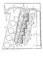
図1はフルカラー画像を形成する画像形成装置の一例を示す垂直断面図であり、ここに示した画像形成装置は、画像形成装置本体1内に配置されたドラム状の感光体より成る第1乃至第4の像担持体2Y,2C,2M,2BKと、同じく画像形成装置本体1内に配置された無端状の中間転写ベルト3を有している。中間転写ベルト3は支持ローラ4,5,6に巻き掛けられて矢印A方向に回転駆動される。
FIG. 1 is a vertical sectional view showing an example of an image forming apparatus for forming a full-color image. The image forming apparatus shown here includes first to thorough drum-shaped photoconductors arranged in an image forming apparatus main body 1. A
上記中間転写ベルト3は、各像担持体2Y乃至2BKの上方に位置し、該中間転写ベルト3の下側の走行辺が各像担持体2Y乃至2BKの周面に当接している。中間転写ベルト3は、各像担持体の表面にそれぞれ形成された互いに異なる色のトナー像が重ねて転写される転写材の一例を構成するものである。 The intermediate transfer belt 3 is positioned above the image carriers 2Y to 2BK, and the lower running side of the intermediate transfer belt 3 is in contact with the peripheral surface of the image carriers 2Y to 2BK. The intermediate transfer belt 3 constitutes an example of a transfer material onto which toner images of different colors formed on the surface of each image carrier are transferred in a superimposed manner.
第1乃至第4の各像担持体2Y,2C,2M,2BK上にトナー像を形成し、そのトナー像を中間転写ベルト3に転写する構成は、そのトナー像の色が異なるだけで、実質的に全て同一であるため、第1の像担持体2Yにトナー像を形成し、そのトナー像を中間転写ベルト3に転写する構成だけを説明する。
The configuration in which a toner image is formed on each of the first to
図2は、この像担持体2Yと、その像担持体2Yの表面にトナー像を形成するための各作像装置を示す拡大図である。像担持体2Yは図2における時計方向に回転駆動され、このとき帯電電圧を印加された帯電ローラ7Yより成る帯電装置によって像担持体2Yが所定の極性に帯電される。帯電後の像担持体2Yには、図1に示した光書き込み装置8から出射する光変調されたレーザビームLが照射され、これによって像担持体2Yに静電潜像が形成される。この静電潜像は、現像装置9Yによってイエロートナー像として可視像化される。
FIG. 2 is an enlarged view showing the image carrier 2Y and each image forming device for forming a toner image on the surface of the image carrier 2Y. The image carrier 2Y is rotationally driven in the clockwise direction in FIG. 2, and at this time, the image carrier 2Y is charged to a predetermined polarity by a charging device including a charging
現像装置9Yは、乾式の現像剤Dを収容した現像ケース10Yと、この現像ケース10Yに回転自在に支持され、かつ該現像ケースに形成された開口を通して像担持体2Yに近接して対向配置された現像ローラ11Yと、現像ローラ11Y上の現像剤量を規制する現像ブレード31Yと、現像ローラ11Yに対向して配置された第1及び第2搬送スクリュー32Y,33Yを有している。現像ケース10Y内の現像剤Dは、第1及び第2搬送スクリュー32Y,33Yによって搬送されながら撹拌され、矢印方向に回転する現像ローラ11Y上に担持されて搬送される。このとき現像ブレード31Yによって、現像ローラ11Y上の現像剤の高さが一定に規制され、規制後の現像剤が現像ローラ11Yと像担持体2Yとの間の現像領域に運ばれ、ここで現像剤中のトナーが像担持体に形成された静電潜像に静電的に移行して、該潜像がトナー像として可視像化される。現像剤として一成分又は二成分のいずれの現像剤を用いることもできるが、ここではトナーとキャリアを有する二成分系現像剤が用いられている。
The developing device 9Y is disposed so as to face the image carrier 2Y in close proximity to the developing
中間転写ベルト3を挟んで、像担持体2Yと反対側に一次転写ローラ12Yが配置され、この一次転写ローラ12Yに転写電圧が印加されることにより、像担持体2Y上のトナー像が、矢印A方向に回転する中間転写ベルト3上に一次転写される。トナー像転写後の像担持体2Y上に付着する転写残トナーはクリーニング装置13Yによって除去される。
A
本例のクリーニング装置13Yは、像担持体2Yを向いた側に開口を有するクリーニングケース34Yと、基端部がそのクリーニングケース34Yに固定支持され、先端部が像担持体2Yの表面に圧接して、該像担持体2Y上の転写残トナーを除去するクリーニングブレード35Yと、除去されたトナーを図示していない廃トナーボトルに搬送する廃トナースクリュー36Yとを有している。帯電ローラ7Yには、直流に交流成分の重畳された帯電電圧が印加されているので、クリーニング装置13Yを通過した像担持体2Yが帯電ローラ7Yを通るとき、除電と同時に帯電され、次の作像に備える。
The
上述したところと全く同様にして、図1に示した第2乃至第4の像担持体2C,2M,2BK上にシアントナー像、マゼンタトナー像及びブラックトナー像がそれぞれ形成され、これらのトナー像がイエロートナー像の転写された中間転写ベルト3上に順次重ねて一次転写され、中間転写ベルト3上に合成トナー像が形成される。トナー像転写後の各像担持体2C,2M,2BK上の転写残トナーがクリーニング装置により除去されることも第1の像担持体2Yの場合と変わりはない。
In the same manner as described above, a cyan toner image, a magenta toner image, and a black toner image are formed on the second to
図1に示すように、第2乃至第4の像担持体2C,2M,2BKのまわりにも第1の像担持体2Yのまわりに設けられた各作像装置と同じく作用する作像装置が配置されているが、図1には、これらの作像装置に対して、第1の像担持体2Yのまわりに設けられた作像装置に付した符号のYの代りにC,M,BKを添えた符号を付してある。
As shown in FIG. 1, there are image forming apparatuses that act similarly to the respective image forming apparatuses provided around the first image carrier 2Y around the second to
一方、図1に示すように、画像形成装置本体1内の下部には、例えば転写紙より成る記録媒体Pを収容した給紙カセット14と、給紙ローラ15を有する給紙装置16が配置され、給紙ローラ15の回転によって最上位の記録媒体Pが矢印B方向に送り出される。送り出された記録媒体は、レジストローラ対17によって、所定のタイミングで支持ローラ4に巻き掛けられた中間転写ベルト3の部分と、これに対置された二次転写ローラ18との間に給送される。このとき、二次転写ローラ18には所定の転写電圧が印加され、これによって中間転写ベルト3上の合成トナー像が記録媒体Pに二次転写される。
On the other hand, as shown in FIG. 1, a
合成トナー像を二次転写された記録媒体Pはさらに上方に搬送されて定着装置19を通り、このとき記録媒体P上のトナー像が熱と圧力の作用により定着される。定着装置19を通過した記録媒体Pは、排紙ローラ対20によって、画像形成装置本体1の上部の排紙部22に排出される。また、トナー像転写後の中間転写ベルト3上に付着する転写残トナーはクリーニング装置24によって除去される。
The recording medium P on which the composite toner image has been secondarily transferred is further conveyed upward and passes through the fixing device 19, and at this time, the toner image on the recording medium P is fixed by the action of heat and pressure. The recording medium P that has passed through the fixing device 19 is discharged by the paper
画像形成装置本体1内の上部であって、後述するプロセスカートリッジ40Y乃至40BKよりも上方の位置に、イエロー、シアン、マゼンタ及びブラックの各色のトナーを収容したトナーボトル37Y,37C,37M,37BKが、画像形成装置本体1に対して着脱可能に装着され、その各トナーボトル37Y乃至37BKから、その各色のトナーが図示していない搬送路を通して、各現像装置9Y,9C,9M,9BKにそれぞれ補給される。
ところで、図2に示した帯電ローラ7Yより成る帯電装置、現像装置9Y及びクリーニング装置13Yは、像担持体2Yにトナー像を形成するための作像装置を構成するものであり、これは、他の像担持体2C,2M,2BKのまわりに設けられた帯電ローラ7C,7M,7BK、現像装置9C,9M,9BK及びクリーニング装置13C,13M,13BKも同様である。
Incidentally, the charging device including the charging
ここで、表面にトナー像が形成される各像担持体2Y乃至2BKと、その各像担持体にトナー像を形成するための少なくとも1つの作像装置とが、それぞれ一体的に組み付けられたプロセスカートリッジ40Y,40C,40M,40BKとして構成され、本例の画像形成装置は、かかるプロセスカートリッジを複数個有し、その各像担持体2Y乃至2BKにそれぞれ形成された互いに異なる色のトナー像を転写材の一例である中間転写ベルト3に転写して記録画像を得るように構成されている。
Here, each image carrier 2Y to 2BK on which a toner image is formed on the surface and at least one image forming device for forming the toner image on each image carrier are integrally assembled. Constructed as
本例の画像形成装置においては、図2に示すように、現像ケース10Yとクリーニングケース34Yが一体化されたユニットケース41Yとして形成され、像担持体2Yがそのユニットケース41Yに回転自在に支持され、当該像担持体2Yと、現像装置9Yと、クリーニング装置13Yと帯電ローラ7Yが一体的に組み付けられてプロセスカートリッジ40Yが構成されている。他の各像担持体2C,2M,2BKと、そのまわりにそれぞれ設けられた作像装置によっても、全く同様なプロセスカートリッジ40C,40M,40BKがそれぞれ構成されている。
In the image forming apparatus of this example, as shown in FIG. 2, the developing
上述のように、像担持体と帯電装置と現像装置とクリーニング装置の全てを一体化してプロセスカートリッジを構成する代りに、像担持体と一部の作像装置とによってプロセスカートリッジを構成してもよい。例えば、像担持体と、その像担持体にトナー像を形成するための帯電装置と現像装置とクリーニング装置の少なくとも1つとによってプロセスカートリッジを構成することができる。 As described above, instead of integrating the image carrier, the charging device, the developing device, and the cleaning device together to form the process cartridge, the process cartridge may be constituted by the image carrier and some image forming devices. Good. For example, a process cartridge can be configured by an image carrier, and at least one of a charging device, a developing device, and a cleaning device for forming a toner image on the image carrier.
図1に示すように、中間転写ベルト3は、同図における右端側が低く、左端側が高くなった傾斜した状態で配置され、各像担持体2Y乃至2BKは、その中間転写ベルト3の下側の走行辺に沿って配置されている。各像担持体2Y乃至2BKが、転写材の一例である中間転写ベルト3の表面移動方向に沿って、上下斜め方向に配列されているのであるが、これに対応して、各プロセスカートリッジ40Y乃至40BKは、上下斜め方向に配列されている。しかも、各プロセスカートリッジ40Y乃至40BKは、画像形成装置本体1に対して、図1及び図2の紙面に対して垂直な方向に着脱できるように構成されている。図示した例では、各プロセスカートリッジ40Y乃至40BKはその各像担持体2Y乃至2BKの軸線方向に着脱される。
As shown in FIG. 1, the intermediate transfer belt 3 is disposed in an inclined state in which the right end side in the drawing is low and the left end side is high, and each of the image carriers 2Y to 2BK is disposed below the intermediate transfer belt 3. It is arranged along the running side. Each of the image carriers 2Y to 2BK is arranged in an oblique direction in the vertical direction along the surface moving direction of the intermediate transfer belt 3 which is an example of the transfer material. 40BK is arranged in the diagonal direction. In addition, each of the
ここで、図1及び図2に示すように、画像形成装置本体1内には、その画像形成装置本体1に固定されたガイド42Y,42C,42M,42BKが設けられ、その各ガイド42Y乃至42BKは、画像形成装置本体1に対する各プロセスカートリッジ40Y乃至40BKの脱着時に、該プロセスカートリッジを下から支えて案内する支え面43Y,43C,43M,43BKを有しており、各プロセスカートリッジを案内する各ガイド42Y乃至42BKの支え面43Y乃至43BKは、各プロセスカートリッジの高さ位置に対応して、互いに高さ位置が異なっている。
As shown in FIGS. 1 and 2, guides 42Y, 42C, 42M, and 42BK fixed to the image forming apparatus main body 1 are provided in the image forming apparatus main body 1, and the
図1及び図2に示した画像形成装置においては、各支え面43Y,43C,43M,43BKが、ほぼ水平に配置され、その各支え面が段々状に配置されている。 In the image forming apparatus shown in FIGS. 1 and 2, the support surfaces 43Y, 43C, 43M, and 43BK are arranged almost horizontally, and the support surfaces are arranged stepwise.
各ガイド42Y乃至42BKと、各プロセスカートリッジ40Y,40C,40M,40BKのユニットケース41Y,41C,41M,41BKには、光書き込み装置8から出射したレーザビームLが各像担持体2Y乃至2BKに至り得るように、光透過窓44Y,44C,44M,44BKがそれぞれ形成されている。
The laser beams L emitted from the
また、プロセスカートリッジ40Y乃至40BK、中間転写ベルト3、光書き込み装置8などの各要素の手前側には、画像形成装置本体1の前側板(図1及び図2には示さず、図5参照)が配置されているが、この前側板には、図1に二点鎖線で示した開口45が形成され、この開口45を通して各プロセスカートリッジ40Y乃至40BKを脱着することができる。
A front plate of the image forming apparatus main body 1 is provided on the front side of each element such as the
また、図5に示すように、画像形成装置本体1の前側板50には面板51が配置され、この面板51は、図5に示した開位置と、開口45を閉鎖する閉位置との間を回動可能に前側板50に連結されている。各プロセスカートリッジ40Y,40C,40M,40BKを画像形成装置本体1内に装着し、面板51を閉位置に移動させたとき、その面板51によって、プロセスカートリッジ40Y乃至40BKの像担持体2Y乃至2BKが最終的に位置決めされ、この状態で画像形成動作が可能となる。
Further, as shown in FIG. 5, a
上述した構成によれば、各プロセスカートリッジ40Y乃至40BKを点検し、或いは修理し、又はこれを交換するとき、その各プロセスカートリッジを各支え面43Y乃至43BKに載せて、各プロセスカートリッジを手前側に引き出し、或いはその各プロセスカートリッジを奥側へ押し込むことができ、プロセスカートリッジを水平にしたまま、その脱着を行うことができる。このため、従来のように、画像形成装置本体に設けられたガイドレールに各プロセスカートリッジに設けられた可動レールを嵌合する作業は不要である。しかも、画像形成装置本体の図示していないドアを開き、面板51を開位置に回動させれば、各ガイド42Y乃至42BKの支え面43Y乃至43BKを即座に目視にて確認でき、その支え面43Y乃至43BKによって各プロセスカートリッジを案内して、これを脱着できることを理解することができる。このため、一般のユーザであっても、各プロセスカートリッジを容易に脱着することができ、しかもその脱着時に各プロセスカートリッジを水平状態に保てるため、その作業を一層容易に行うことができる。
According to the above-described configuration, when the
また、プロセスカートリッジの脱着時に、プロセスカートリッジがその脱着方向に対して直交する方向にずれ動くことを規制する規制手段を設けると、或るプロセスカートリッジの脱着時に、当該プロセスカートリッジがその隣りに位置するプロセスカートリッジに干渉することを防止でき、プロセスカートリッジが破損する不具合を阻止できる。 Further, if a restricting means is provided for restricting the movement of the process cartridge in a direction perpendicular to the removal direction when the process cartridge is detached, the process cartridge is positioned next to the process cartridge when it is removed. Interference with the process cartridge can be prevented, and problems that the process cartridge is damaged can be prevented.
例えば、図1及び図2に示すように、各ガイド42Y乃至42BKに、その支え面43Y乃至43BKよりも上方に突出し、かつプロセスカートリッジの脱着方向に延びるガイド突起46(詳しくは図2を参照)より成る規制手段を設け、そのガイド突起46に、各プロセスカートリッジ40Y乃至40BKのユニットケース41Y乃至41BKに形成されている溝部48(同じく図2参照)を摺動自在に嵌合し、各プロセスカートリッジの脱着時にそのプロセスカートリッジが水平方向に大きくずれ動くことを阻止する。勿論、各プロセスカートリッジの側にガイド突起を設け、各ガイドに、そのガイド突起が摺動自在に嵌合するガイド溝を形成し、かかるガイド突起とガイド溝より成る規制手段によって、プロセスカートリッジの脱着時に、これが水平方向に大きくずれ動くことを阻止してもよい。
For example, as shown in FIG. 1 and FIG. 2, guide
また、図2に示すように、ガイド突起46と反対側のユニットケース41Yの側部に突部52Yを設け、プロセスカートリッジ40Yの脱着時に、その突部52Yを、支え面43Yに対して立ち上がった壁部53に摺擦させ、プロセスカートリッジ40Yがずれ動くことをより確実に阻止できるように構成することもできる。突部52Yと壁部53も規制手段の一例を構成するものであり、かかる規制手段は、他のプロセスカートリッジ40C,40M,40BKに対しても付設することができる。
Further, as shown in FIG. 2, a
また、図3に示すように、各ガイド42Y乃至42BKに、形態や取付位置の異なるガイド突起46Y乃至46BKを設け、各プロセスカートリッジ40Y乃至40BKには、その各ガイド突起46Y乃至46BKに嵌合するガイド溝を形成することもできる。図4は、図3の一番左側に位置するガイド突起46Yに嵌合できるガイド溝47Yをプロセスカートリッジ40Yのユニットケース41Yに形成した例を示している。
As shown in FIG. 3, the
上述のように構成すれば、例えば図4に示したプロセスカートリッジ40Yのガイド溝47Yは、他のガイド突起46C,46M,46BKに嵌合できないので、そのプロセスカートリッジ40Yを誤った位置にセットしてしまうことはない。各ガイド42Y乃至42BKに、正規のプロセスカートリッジ40Y乃至40BKだけをセットできるようにするのである。各ガイドにガイド溝を形成し、各プロセスカートリッジにガイド突起を設けて、同じようにプロセスカートリッジの誤セットを防止できるように構成することもできる。
If configured as described above, for example, the
上述のように、規制手段が、正規のプロセスカートリッジ以外のプロセスカートリッジが装着されることを禁止する誤セット防止機能を有していると、プロセスカートリッジの誤セットを未然に防止でき、各現像装置に誤った色のトナーを補給したり、混色によってトナー像の画質が劣化する不具合を阻止できる。 As described above, if the restricting means has an erroneous setting prevention function for prohibiting the mounting of process cartridges other than the regular process cartridge, the erroneous setting of the process cartridge can be prevented in advance. Incorrect color toner can be replenished, and a problem that the image quality of the toner image deteriorates due to color mixture can be prevented.
また、ガイド42Y乃至42BKを、図示していない昇降装置によって上下動可能に支持することもできる。このように構成すれば、プロセスカートリッジの脱着時に、そのプロセスカートリッジを下方に下げ、像担持体を中間転写ベルト3から確実に離間させることができるので、像担持体と中間転写ベルト3との摺擦により、これらの表面に傷が付けられる不具合を阻止できる。
Further, the
その際、複数のガイド42Y乃至42BKの全体が一体に上下動するように構成してもよいが、各プロセスカートリッジ40Y乃至40BKを案内する各ガイド42Y乃至42BKがそれぞれ単独で上下動可能となっていると、必要なガイドだけを上下動できるので、プロセスカートリッジの脱着作業を簡素化することができる。
At this time, the whole of the plurality of
また、先に説明したように、本例の画像形成装置においては、各プロセスカートリッ40Y乃至40BKが、像担持体2Y乃至2BKにトナー像を形成する現像装置9Y乃至9BKを有し、その各現像装置9Y乃至9BKに供給されるトナーを収容したトナーボトル37Y,37C,37M,37BKが、各プロセスカートリッジ40Y乃至40BKとは別に画像形成装置本体1に脱着可能に装着されている。このため、ユーザは、通常、トナーボトル37Y乃至37BKの交換を行うだけでよく、プロセスカートリッジ40Y乃至40BKを交換する必要が生じたときだけ、そのプロセスカートリッジの交換作業を行えばよい。トナーが無くなったとき、プロセスカートリッジまでも交換する必要がないため、ユーザへの経済的負担を軽減できる。
Further, as described above, in the image forming apparatus of this example, each
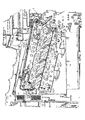
図6は画像形成装置の他の例を示す概略図であり、ここに示した画像形成装置の基本構成は図1及び図2に示した画像形成装置と変りはない。すなわち、図6に示した画像形成装置も、トナー像が形成される像担持体と該像担持体にトナー像を形成するための少なくとも1つの作像装置とが一体的に組み付けられたプロセスカートリッジ40Y,40C,40M,40BKを複数個有し、各像担持体にそれぞれ形成された互いに異なる色のトナー像を中間転写ベルトより成る転写材に転写して記録画像を得るように構成され、その各プロセスカートリッジ40Y乃至40BKは、上下斜め方向に配列されていると共に、画像形成装置本体1に対して脱着可能に構成されている。しかも、画像形成装置本体1に対する各プロセスカートリッジ40Y乃至40BKの脱着時に、該プロセスカートリッジ40Y乃至40BKを下から支えて案内する支え面43Y,43C,43M,43BKを有するガイド42Y,42C,42M,42BKが設けられ、その各支え面43Y乃至43BKは互いに高さ位置が異なっている。
FIG. 6 is a schematic diagram showing another example of the image forming apparatus, and the basic configuration of the image forming apparatus shown here is the same as that of the image forming apparatus shown in FIGS. That is, the image forming apparatus shown in FIG. 6 is also a process cartridge in which an image carrier on which a toner image is formed and at least one image forming device for forming a toner image on the image carrier are integrally assembled. A plurality of 40Y, 40C, 40M, and 40BK, each configured to transfer a toner image of a different color formed on each image carrier onto a transfer material including an intermediate transfer belt to obtain a recorded image; Each of the
図6においては、中間転写ベルトがそのケースに収容された状態で示されていて、該ベルトは図には表わされていない。この中間転写ベルトも、図1に示した中間転写ベルト3と同じく、その下側の走行辺が水平面に対して約15度程度の角度をもって配置され、その中間転写ベルト3に、各プロセスカートリッジ40Y乃至40BKの像担持体からトナー像が転写され、そのトナー像が記録媒体に転写される。
In FIG. 6, the intermediate transfer belt is shown accommodated in the case, and the belt is not shown in the drawing. Similarly to the intermediate transfer belt 3 shown in FIG. 1, this intermediate transfer belt is also arranged with its lower running side at an angle of about 15 degrees with respect to the horizontal plane, and each
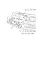
図7は、図6に示したプロセスカートリッジ40Y乃至40BKを取り出した後の画像形成装置本体を示す図である。この図から判るように、この画像形成装置が図1及び図2に示した画像形成装置と異なるところは、各ガイド42Y乃至42BKの支え面43Y乃至43BKが、傾斜して配置されている点である。
FIG. 7 is a view showing the main body of the image forming apparatus after the
この例でも、各像担持体に形成された各色のトナー像が転写される転写材が、各プロセスカートリッジの像担持体が当接する中間転写ベルトより成るが、各支え面43Y乃至43BKが、中間転写ベルトの下側の走行辺とほぼ平行に位置しているのである。各プロセスカートリッジ40Y乃至40BKは、かかる支え面43Y乃至43BKに案内されながら、図7に矢印E,Fで示すように、画像形成装置本体1内に装着され、又は画像形成装置本体1から引き出される。各支え面43Y乃至43BKには、光書き込み装置から出射したレーザービームが通過する光透過窓44Y乃至44BKが形成されている。
In this example as well, the transfer material onto which the toner images of the respective colors formed on the image carriers are transferred consists of an intermediate transfer belt with which the image carrier of each process cartridge abuts, but the support surfaces 43Y to 43BK are intermediate. It is located substantially parallel to the lower running side of the transfer belt. Each
図9はプロセスカートリッジ40Y乃至40BKを示す斜視図であり、図10はガイド42Y乃至42BKに案内されて画像形成装置本体内に装着されたプロセスカートリッジ40Y乃至40BKを示す正面図である。また、図11及び図12は画像形成装置本体内に装着されたプロセスカートリッジ40Y乃至40BKの手前側の様子を示す斜視図である。図9及び図12における矢印E,Fも、図7と同様にプロセスカートリッジを画像形成装置本体内に押し込んで装着するときの方向と、画像形成装置本体からプロセスカートリッジを引き出すときの方向を示している。
FIG. 9 is a perspective view showing the
図6及び図7に示した画像形成装置にも、プロセスカートリッジの脱着時に、該プロセスカートリッジがその脱着方向に対して直交する方向にずれ動くことを規制する規制手段が設けられている。この規制手段は、図8にも示すように、各支え面43Y乃至43BKに対して、上方に向けてほぼ直角に立ち上がった板材より成る規制部54Y,54C,54M,54BKを有し、各支え面と規制部とによってほぼL字形断面のガイド42Y乃至42BKが構成されている。
The image forming apparatus shown in FIGS. 6 and 7 is also provided with restricting means for restricting the process cartridge from moving in a direction perpendicular to the attaching / detaching direction when the process cartridge is attached / detached. As shown in FIG. 8, the restricting means has restricting
プロセスカートリッジ40Y乃至40BKを矢印F,Eで示すように画像形成装置本体1に対して脱着する時、各支え面43Y乃至43BKは、プロセスカートリッジ40Y乃至40BKのほぼ平坦に形成された下面を案内するが、このとき、各プロセスカートリッジ40Y乃至40BKが、その自重によって各規制部54Y乃至54BKに当接する。各規制部54Y乃至54BKは、各プロセスカートリッジ40Y乃至40BKの脱着時に、そのプロセスカートリッジの側部を支えて、当該プロセスカートリッジの幅方向W(図9)のずれ動きを規制するのである。このようにして、各プロセスカートリッジ40Y乃至40BKは、各ガイド42Y乃至42BKによって、幅方向Wにずれ動くことなく、スムーズに画像形成装置本体に対して脱着される。なお、プロセスカートリッジの幅方向Wとは、図9に示すように、各プロセスカートリッジ40Y乃至40BKの長手方向Lに対して直交する方向の幅である。
When the
ところで、各プロセスカートリッジ40Y乃至40BKを画像形成装置本体1に対して脱着する際、そのプロセスカートリッジの像担持体が中間転写ベルトに当って摺擦すると、その像担持体や中間転写ベルトの表面に傷が付けられるおそれがある。
By the way, when the
そこで、本例の画像形成装置の規制手段は、図7及び図8に示すように、プロセスカートリッジ40Y乃至40BKの脱着時に、該プロセスカートリッジの上方への動きを規制する上下案内部55Y,55C,55M,55BKを有している。ここに示した例では、板金などの板材より成る規制部54Y乃至54BKの一部を切り起こすことにより、板状の上下案内部55Y乃至55BKが形成されている。各上下案内部55Y乃至55BKは、各支え面43Y乃至43BKから上方に離間して位置している。
Therefore, as shown in FIGS. 7 and 8, the restricting means of the image forming apparatus of the present example includes upper and
一方、図9に示すように、各プロセスカートリッジ40Y乃至40BKのユニットケース41Y乃至41BKには、その先端側に、突片より成る係合部56が突設されている。プロセスカートリッジの先端側とは、そのプロセスカートリッジを画像形成装置本体内に装着したとき、奥側となる側である。
On the other hand, as shown in FIG. 9, the
各プロセスカートリッジ40Y乃至40BKを各ガイド42Y乃至42BKによって案内しながら画像形成装置本体1の内部へ押し込んで装着するとき、各プロセスカートリッジの係合部56が、図7及び図8に示した各上下案内部55Y乃至55BKの下側面にそれぞれ係合する。各プロセスカートリッジ40Y乃至40BKを画像形成装置本体1から引き出すときも同様である。これにより、プロセスカートリッジの着脱時に、そのプロセスカートリッジが上方へ移動して、像担持体が中間転写ベルトに当接することを阻止でき、像担持体が中間転写ベルトの表面に摺擦してこれらの表面に傷が付けられることはない。
When the
上述のように、画像形成装置本体1に対して脱着可能に装着される各プロセスカートリッジ40Y乃至40BKは、各支え面43Y乃至43BKに案内されるように、該プロセスカートリッジ40Y乃至40BKの下面がほぼ平坦に形成され、しかも各プロセスカートリッジ40Y乃至40BKの側部には、画像形成装置本体1へのプロセスカートリッジ40Y乃至40BKの脱着時に、画像形成装置本体1側に設けられた上下案内部55Y乃至55BKに係合する係合部56が設けられ、該係合部56が上下案内部55Y乃至55BKに係合することにより、当該プロセスカートリッジ40Y乃至40BKが上方に動くことが規制されるように構成されている。
As described above, the
また、図7に示すように、各上下案内部55Y乃至55BKの画像形成装置本体前後方向の長さが支え面43Y乃至43BKの長さよりも短く設定され、各プロセスカートリッジ40Y乃至40BKを画像形成装置本体1内に挿入し、該プロセスカートリッジが途中まで画像形成装置本体内に挿入されたとき、プロセスカートリッジの突片状の係合部56が、板状の上下案内部55Y乃至55BKを抜け出るように構成されている。このようにすれば、プロセスカートリッジを画像形成装置本体1内の所定の位置まで挿入し終えたとき、プロセスカートリッジは上方に向けて移動することができるので、そのプロセスカートリッジの像担持体を中間転写ベルトに当接させることができる。上下案内部55Y乃至55BKが、プロセスカートリッジ40Y乃至40BKを画像形成装置本体1内に装着するとき、その途中まで、プロセスカートリッジ40Y乃至40BKの上方への動きを規制するように構成されているのである。
Further, as shown in FIG. 7, the lengths of the
しかも、本例の画像形成装置においては、図7に示すように、各支え面43Y乃至43BKの奥側の部位にその各支え面よりも上方に突出した膨隆部57Y,57C,57M,57BKが設けられていて、プロセスカートリッジ40Y乃至40BKを画像形成装置本体1内に押し込んで行き、その係合部56が上下案内部55Y乃至55BKを抜け出た後、各プロセスカートリッジ40Y乃至40BKが各膨隆部57Y乃至57BKに乗り上げ、そのプロセスカートリッジが上方に持ち上げられて各プロセスカートリッジの各像担持体が中間転写ベルトの表面に当接するように構成されている。
In addition, in the image forming apparatus of this example, as shown in FIG. 7, the bulging
上述した上下案内部と、これに関連する構成は、図1乃至図5に示した画像形成装置にも適用できるものである。 The above-described vertical guide unit and the configuration related thereto can also be applied to the image forming apparatus shown in FIGS.
また、各プロセスカートリッジ40Y乃至40BKを画像形成装置本体1内に押し込んで装着したとき、その各プロセスカートリッジを所定の正しい位置に位置決めする必要がある。
Further, when each
そこで、本例の画像形成装置においては、図7、図8、図11、及び図12に示すように、規制部54Y乃至54BKを構成する板金などの板材の手前側の領域に位置決め穴58Y,58C,58M,58BKが形成されている。一方、図9、図11及び図12に示すように、各プロセスカートリッジ40Y乃至40BKのユニットケース41Y乃至41BKの手前側領域には、基準突部59より成る基準部が設けられている。
Therefore, in the image forming apparatus of this example, as shown in FIGS. 7, 8, 11, and 12, the positioning holes 58Y, 58B are formed in the area on the near side of the sheet material such as a sheet metal constituting the restricting
各プロセスカートリッジ40Y乃至40BKを画像形成装置本体1内の一番奥の位置まで挿入すると、各プロセスカートリッジに形成された基準突部59が、図11及び図12に示すように、各規制部54Y乃至54BKに形成された位置決め穴58Y乃至58BKに、各プロセスカートリッジの自重によって落ち込み、当該位置決め穴58Y乃至58BKに係合する。これにより、各プロセスカートリッジ40Y乃至40BKは、画像形成装置本体内で、その各プロセスカートリッジ40Y乃至40BKの長手方向Lに位置決めされる。このとき、プロセスカートリッジ40Y乃至40BKは、画像形成装置本体1の奥側から、図示していない付勢手段、例えば圧縮ばねによって付勢されるので、各プロセスカートリッジ40Y乃至40BKが長手方向Lに位置決めされると共に、その位置決めされた位置にロックされる。各位置決め穴58Y乃至58BKは、各プロセスカートリッジ40Y乃至40BKを位置決めする位置決め部の一例を構成するものである。
When each of the
上述のように、本例の画像形成装置は、プロセスカートリッジ40Y乃至40BKを画像形成装置本体1内に装着したとき、該プロセスカートリッジ40Y乃至40BKをその長手方向Lに位置決めする位置決め部を有している。
As described above, the image forming apparatus of this example includes a positioning unit that positions the
換言すれば、プロセスカートリッジ40Y乃至40BKは、そのプロセスカートリッジが画像形成装置本体1内に装着されたとき、画像形成装置本体1の側に設けられた位置決め部に係合する基準部を有し、該基準部が位置決め部に係合することによって、その長手方向Lに位置決めされるように構成されているのである。
In other words, each of the
上述した基準部と位置決め部とによって、プロセスカートリッジを完全に位置決めすることもできるが、基準部と位置決め部によりプロセスカートリッジを仮位置決めし、先に説明した実施形態例の画像形成装置と同じく、図5に示した面板51を閉位置にもたらすことによって、各プロセスカートリッジ40Y乃至40BKを最終的に完全に位置決めするように構成することもできる。
Although the process cartridge can be completely positioned by the reference portion and the positioning portion described above, the process cartridge is temporarily positioned by the reference portion and the positioning portion, and similarly to the image forming apparatus of the embodiment described above, By bringing the
プロセスカートリッジ40Y乃至40BKを画像形成装置本体1から取り出すときは、各プロセスカートリッジの基準突部59を各位置決め孔58Y乃至58BKから外して、該プロセスカートリッジに対する長手方向Lの位置決めを解除し、次いでそのプロセスカートリッジを手前側に引き出せばよい。その際、この位置決めの解除を次のように行えるように構成すると有利である。
When the
図9乃至図12に示すように、各プロセスカートリッジ40Y乃至40BKのユニットケース手前側の部位には、把手60が取り付けられており、この把手60は、図12に符号Xを付して示した使用位置と、符号Yを付して示した格納位置の間を矢印Z方向に回動可能にユニットケース41Y乃至41BKに枢着されている。図9、図10及び図11は、把手60が格納位置に収められたときの様子を示している。
As shown in FIGS. 9 to 12, a
プロセスカートリッジ40Y乃至40BKが画像形成装置本体1内に装着されて使用されているとき、把手60は格納位置を占めている。プロセスカートリッジを画像形成装置本体1から取り出すときは、把手60を図12に示した使用位置Xに回動する。すると、この把手60の基端側に設けられたカム部61が、板材より成る規制部54Y乃至54BKの壁面に当接してこれを加圧する。このため、プロセスカートリッジ40Y乃至40BKは、規制部54Y乃至54BKから受ける反力によって、その規制部から離間する方向にわずか動かされる。これによって、プロセスカートリッジ40Y乃至40BKの基準突部59が位置決め孔58Y乃至58BKから外れる。そこで、その把手60を掴んで、これを手前側に引けば、プロセスカートリッジ40Y乃至40BKを手前側に引き出すことができる。
When the
上述のように、プロセスカートリッジ40Y乃至40BKは、そのユニットケース41Y乃至41BKに対して、使用位置と格納位置との間を回動可能に連結された把60を有し、該把手60をその使用位置にもたらしたとき、当該把手60によって、プロセスカートリッジ40Y乃至40BKの長手方向Lの位置決めが解除されるのである。
As described above, the
上述した位置決め部と基準部、及び把手60の構成は、図1乃至図5に示した画像形成装置にも適用できるものである。
The configurations of the positioning unit, the reference unit, and the
図6乃至図12に示した画像形成装置と、そのプロセスカートリッジの他の部分は、図1乃至図5に示した画像形成装置及びプロセスカートリッジと同じく構成することができ、その同じ部分についてのこれ以上の説明は省略する。 The image forming apparatus shown in FIGS. 6 to 12 and other parts of the process cartridge can be configured in the same manner as the image forming apparatus and process cartridge shown in FIGS. 1 to 5. The above description is omitted.
以上説明した画像形成装置においては、各像担持体に形成されたトナー像が中間転写ベルトよりなる転写材に転写されるように構成されているが、各像担持体に形成されたトナー像を記録媒体に直に重ねて転写する画像形成装置にも本発明を適用できる。この場合には、その記録媒体が、各像担持体にそれぞれ形成された互いに異なる色のトナー像を転写される転写材を構成する。 In the image forming apparatus described above, the toner image formed on each image carrier is configured to be transferred to a transfer material including an intermediate transfer belt. However, the toner image formed on each image carrier is The present invention can also be applied to an image forming apparatus that directly superimposes and transfers onto a recording medium. In this case, the recording medium constitutes a transfer material to which toner images of different colors formed on the respective image carriers are transferred.
1 画像形成装置本体
2Y,2C,2M,2BK 像担持体
3 中間転写ベルト
9Y,9C,9M,9BK 現像装置
37Y,37C,37M,37BK トナーボトル
40Y,40C,40M,40BK プロセスカートリッジ
42Y,42C,42M,42BK ガイド
43Y,43C,43M,43BK 支え面
51 面板
54Y,54C,54M,54BK 規制部
55Y,55C,55M,55BK 上下案内部
60 把手
L 長手方向
W 幅方向
DESCRIPTION OF SYMBOLS 1 Image forming apparatus
Claims (17)
画像形成装置本体に対する各プロセスカートリッジの脱着時に該プロセスカートリッジを下から支えて案内する支え面を有するガイドを設け、各支え面は互いに高さ位置が異なっていることを特徴とする画像形成装置。 There are a plurality of process cartridges in which an image carrier on which a toner image is formed and at least one image forming device for forming a toner image on the image carrier are integrally assembled. An image forming apparatus that obtains a recorded image by transferring formed toner images of different colors to a transfer material, wherein each of the process cartridges is arranged in an obliquely upward and downward direction with respect to the main body of the image forming apparatus In the image forming apparatus configured to be detachable,
An image forming apparatus comprising a guide having a support surface that supports and guides the process cartridge from below when the process cartridge is attached to and detached from the image forming apparatus main body, and the support surfaces have different height positions.
Priority Applications (1)
| Application Number | Priority Date | Filing Date | Title |
|---|---|---|---|
| JP2009278063A JP4494519B2 (en) | 2002-12-20 | 2009-12-07 | Image forming apparatus |
Applications Claiming Priority (2)
| Application Number | Priority Date | Filing Date | Title |
|---|---|---|---|
| JP2002371154 | 2002-12-20 | ||
| JP2009278063A JP4494519B2 (en) | 2002-12-20 | 2009-12-07 | Image forming apparatus |
Related Parent Applications (1)
| Application Number | Title | Priority Date | Filing Date |
|---|---|---|---|
| JP2003421966A Division JP4471153B2 (en) | 2002-12-20 | 2003-12-19 | Image forming apparatus |
Publications (2)
| Publication Number | Publication Date |
|---|---|
| JP2010055114A true JP2010055114A (en) | 2010-03-11 |
| JP4494519B2 JP4494519B2 (en) | 2010-06-30 |
Family
ID=32376353
Family Applications (1)
| Application Number | Title | Priority Date | Filing Date |
|---|---|---|---|
| JP2009278063A Expired - Lifetime JP4494519B2 (en) | 2002-12-20 | 2009-12-07 | Image forming apparatus |
Country Status (4)
| Country | Link |
|---|---|
| US (1) | US7024133B2 (en) |
| EP (1) | EP1431837B1 (en) |
| JP (1) | JP4494519B2 (en) |
| CN (1) | CN100407065C (en) |
Cited By (2)
| Publication number | Priority date | Publication date | Assignee | Title |
|---|---|---|---|---|
| JP2013195709A (en) * | 2012-03-19 | 2013-09-30 | Fuji Xerox Co Ltd | Image forming apparatus |
| JP2016177094A (en) * | 2015-03-19 | 2016-10-06 | 富士ゼロックス株式会社 | Image formation device |
Families Citing this family (48)
| Publication number | Priority date | Publication date | Assignee | Title |
|---|---|---|---|---|
| US6631247B1 (en) | 1999-09-29 | 2003-10-07 | Ricoh Co., Ltd. | Method and system for remote diagnostic, control and information collection based on various communication modes for sending messages to a resource manager |
| JP4063498B2 (en) * | 2000-03-02 | 2008-03-19 | 株式会社リコー | Image forming apparatus |
| JP2004139031A (en) | 2002-09-24 | 2004-05-13 | Ricoh Co Ltd | Image forming apparatus, replenishment toner storage container, and process cartridge |
| JP4383898B2 (en) * | 2003-02-28 | 2009-12-16 | 株式会社リコー | Developer container, developer supply device, and image forming apparatus |
| US7158730B2 (en) * | 2003-08-07 | 2007-01-02 | Ricoh Company, Ltd. | Image forming apparatus, process cartridge, developing unit, and image forming method |
| US7421239B2 (en) * | 2003-08-26 | 2008-09-02 | Ricoh Company, Ltd. | Cleaning apparatus for removing toner adhered onto endless belt |
| JP4587269B2 (en) * | 2003-10-27 | 2010-11-24 | 株式会社リコー | Process cartridge replacement method, device unit replacement method |
| JP4341957B2 (en) * | 2003-12-25 | 2009-10-14 | 株式会社リコー | Image forming apparatus |
| JP2005221825A (en) * | 2004-02-06 | 2005-08-18 | Ricoh Co Ltd | Toner bottle, its production method, toner container, toner cartridge, and image forming apparatus |
| JP4656561B2 (en) * | 2004-03-05 | 2011-03-23 | 株式会社リコー | Toner container, toner supply device, developing device, process cartridge, and image forming apparatus |
| JP2005300626A (en) * | 2004-04-07 | 2005-10-27 | Ricoh Co Ltd | Cleaning device and image forming apparatus |
| JP2005315913A (en) * | 2004-04-26 | 2005-11-10 | Ricoh Co Ltd | Image forming apparatus |
| JP4490195B2 (en) * | 2004-07-12 | 2010-06-23 | 株式会社リコー | Image forming apparatus |
| JP4616591B2 (en) * | 2004-07-20 | 2011-01-19 | 株式会社リコー | Image forming apparatus |
| US7720416B2 (en) | 2004-08-16 | 2010-05-18 | Ricoh Company, Ltd. | Method and toner bottle for image forming apparatus capable of effectively supplying toner to image forming apparatus |
| JP4519589B2 (en) * | 2004-09-17 | 2010-08-04 | 株式会社リコー | Image forming apparatus |
| US7447469B2 (en) * | 2004-10-18 | 2008-11-04 | Ricoh Company, Ltd. | Image forming device and mounting member for mounting a toner container thereon |
| JP4750403B2 (en) | 2004-11-12 | 2011-08-17 | キヤノン株式会社 | Image forming apparatus |
| JP4755867B2 (en) | 2004-11-26 | 2011-08-24 | 株式会社リコー | Developing device, process cartridge including the same, and image forming apparatus |
| JP4649189B2 (en) * | 2004-12-10 | 2011-03-09 | キヤノン株式会社 | Image forming apparatus |
| JP2006251301A (en) | 2005-03-10 | 2006-09-21 | Ricoh Co Ltd | Developing device, process cartridge and image forming apparatus using the same, and toner |
| JP4885526B2 (en) | 2005-11-30 | 2012-02-29 | 株式会社リコー | Image forming apparatus |
| JP4764743B2 (en) * | 2005-12-20 | 2011-09-07 | 株式会社リコー | Developing device, image forming apparatus |
| JP2007248982A (en) * | 2006-03-17 | 2007-09-27 | Ricoh Co Ltd | Image forming apparatus and toner |
| JP4820689B2 (en) | 2006-05-15 | 2011-11-24 | 株式会社リコー | Developing device, process cartridge, and image forming apparatus |
| JP2008046240A (en) * | 2006-08-11 | 2008-02-28 | Ricoh Co Ltd | Developing device, process cartridge and image forming apparatus |
| JP2008070570A (en) | 2006-09-13 | 2008-03-27 | Ricoh Co Ltd | Developing device and image forming apparatus |
| JP2009047714A (en) * | 2006-09-19 | 2009-03-05 | Ricoh Co Ltd | Developer carrying device, developing device, process unit, and image forming apparatus |
| JP2008102492A (en) * | 2006-09-19 | 2008-05-01 | Ricoh Co Ltd | Developer transferring device, developing device, process unit and image forming apparatus |
| JP2008102489A (en) * | 2006-09-19 | 2008-05-01 | Ricoh Co Ltd | Developer conveying device, developing device, process unit, and image forming apparatus |
| JP2008249835A (en) | 2007-03-29 | 2008-10-16 | Ricoh Co Ltd | Developing device and image forming apparatus |
| JP2008256901A (en) * | 2007-04-04 | 2008-10-23 | Ricoh Co Ltd | Developing device, process cartridge, and image forming apparatus |
| JP5137647B2 (en) | 2007-05-15 | 2013-02-06 | キヤノン株式会社 | Image forming apparatus |
| JP5159225B2 (en) * | 2007-09-21 | 2013-03-06 | キヤノン株式会社 | Image forming apparatus |
| US8135305B2 (en) * | 2007-10-18 | 2012-03-13 | Canon Kabushiki Kaisha | Image forming apparatus |
| US8036575B2 (en) * | 2007-10-19 | 2011-10-11 | Ricoh Company, Limited | Development device, image forming apparatus, and process cartridge having compact structure for discharging developer |
| JP5348381B2 (en) * | 2007-11-15 | 2013-11-20 | 株式会社リコー | Image forming apparatus |
| JP5187114B2 (en) * | 2008-02-25 | 2013-04-24 | 株式会社リコー | Developing device, process cartridge, and image forming apparatus |
| JP5004870B2 (en) * | 2008-05-23 | 2012-08-22 | キヤノン株式会社 | Process cartridge and electrophotographic image forming apparatus |
| JP5230265B2 (en) * | 2008-05-23 | 2013-07-10 | キヤノン株式会社 | Image forming apparatus and process cartridge |
| JP5299686B2 (en) * | 2008-08-08 | 2013-09-25 | 株式会社リコー | Process cartridge and image forming apparatus |
| EP2273318A3 (en) * | 2009-07-08 | 2016-08-31 | Ricoh Company, Ltd. | Development device and image forming apparatus |
| JP5402557B2 (en) * | 2009-11-19 | 2014-01-29 | 富士ゼロックス株式会社 | Image forming apparatus |
| JP5640354B2 (en) * | 2009-11-20 | 2014-12-17 | 富士ゼロックス株式会社 | Image forming apparatus |
| JP2011107557A (en) * | 2009-11-20 | 2011-06-02 | Fuji Xerox Co Ltd | Image forming apparatus |
| CN102135751B (en) | 2010-01-27 | 2014-08-20 | 京瓷办公信息系统株式会社 | Process unit positioning device and image forming apparatus including the same |
| JP6287982B2 (en) * | 2015-07-13 | 2018-03-07 | 京セラドキュメントソリューションズ株式会社 | Image forming apparatus |
| JP6520811B2 (en) * | 2016-04-28 | 2019-05-29 | 京セラドキュメントソリューションズ株式会社 | Unit attaching / detaching mechanism and image forming apparatus provided with the same |
Citations (8)
| Publication number | Priority date | Publication date | Assignee | Title |
|---|---|---|---|---|
| JPH03180861A (en) * | 1989-12-08 | 1991-08-06 | Matsushita Electric Ind Co Ltd | Image recorder |
| JPH08152774A (en) * | 1994-11-26 | 1996-06-11 | Mita Ind Co Ltd | Toner replenishment device |
| JPH1195515A (en) * | 1997-09-18 | 1999-04-09 | Ricoh Co Ltd | Image forming device |
| JP2000098829A (en) * | 1998-09-17 | 2000-04-07 | Canon Inc | Process cartridge and electrophotographic image forming device |
| JP2001331012A (en) * | 2000-05-24 | 2001-11-30 | Matsushita Electric Ind Co Ltd | Image forming device |
| JP2001356546A (en) * | 2000-06-13 | 2001-12-26 | Minolta Co Ltd | Image forming device |
| JP2002062711A (en) * | 2000-06-05 | 2002-02-28 | Ricoh Co Ltd | Image forming apparatus |
| JP2002139976A (en) * | 2000-10-30 | 2002-05-17 | Ricoh Co Ltd | Unit holding device and image forming device having the same |
Family Cites Families (73)
| Publication number | Priority date | Publication date | Assignee | Title |
|---|---|---|---|---|
| JPS6364068A (en) * | 1986-09-05 | 1988-03-22 | Ricoh Co Ltd | Electrostatic recorder |
| JP2750853B2 (en) * | 1986-11-20 | 1998-05-13 | 株式会社リコー | Toner for developing electrostatic latent images |
| US5759733A (en) * | 1987-11-28 | 1998-06-02 | Ricoh Company, Ltd. | Liquid developer for electrostatic electrophotography |
| US4985733A (en) * | 1988-04-02 | 1991-01-15 | Ricoh Company, Ltd. | Image fixing unit for use in wet-type electrophotographic copying machine |
| DE3910459A1 (en) * | 1988-04-02 | 1989-10-19 | Ricoh Kk | Picture-fusing unit for use in an electrophotographic wet copier |
| JP2786856B2 (en) * | 1988-05-17 | 1998-08-13 | 株式会社リコー | Electrophotographic developer |
| JP2774530B2 (en) * | 1988-10-18 | 1998-07-09 | 株式会社リコー | Electrophotographic toner |
| JPH02217870A (en) * | 1989-02-20 | 1990-08-30 | Ricoh Co Ltd | Liquid developer for heat roll fixing |
| US5328794A (en) * | 1989-04-12 | 1994-07-12 | Ricoh Company, Ltd. | Fluorine-containing graft copolymer and toner using the same |
| US5189102A (en) * | 1990-01-30 | 1993-02-23 | Ricoh Company, Ltd. | Method for producing a vinyl resin using a silicon oil solvent |
| JP3208193B2 (en) * | 1991-12-09 | 2001-09-10 | 株式会社リコー | Sheet feeding method for image forming apparatus and sheet feeding apparatus for executing the sheet feeding method |
| JP3198154B2 (en) | 1992-05-13 | 2001-08-13 | 株式会社リコー | Image forming device |
| JPH07128975A (en) * | 1993-10-29 | 1995-05-19 | Ricoh Co Ltd | Image forming device |
| US6249661B1 (en) * | 1993-12-08 | 2001-06-19 | Ricoh Company, Ltd. | Device for supporting an image carrier included in an image forming apparatus |
| DE4446997B4 (en) * | 1993-12-28 | 2005-11-24 | Ricoh Co., Ltd. | Developing device for an image forming device |
| JPH0815990A (en) * | 1994-04-28 | 1996-01-19 | Ricoh Co Ltd | Developing device |
| US5625438A (en) * | 1994-05-12 | 1997-04-29 | Ricoh Company, Ltd. | Toner, and devices for electrostatically depositing a uniform application thereof |
| JPH0830041A (en) * | 1994-05-13 | 1996-02-02 | Ricoh Co Ltd | Developing device |
| US5689782A (en) * | 1994-06-08 | 1997-11-18 | Ricoh Company, Ltd. | Developing apparatus for electronic photographic recording equipment, having two developer transfer rollers |
| DE19521960B4 (en) * | 1994-06-17 | 2008-03-13 | Ricoh Co., Ltd. | Recording method using an ink composition |
| JPH0882999A (en) * | 1994-09-09 | 1996-03-26 | Ricoh Co Ltd | Developing device |
| JPH0882998A (en) * | 1994-09-09 | 1996-03-26 | Ricoh Co Ltd | Developing device |
| JP3384914B2 (en) * | 1994-10-04 | 2003-03-10 | 株式会社リコー | Developing device |
| JPH08146747A (en) * | 1994-11-23 | 1996-06-07 | Ricoh Co Ltd | Developing device |
| JP3501428B2 (en) * | 1994-12-16 | 2004-03-02 | 株式会社リコー | Toner conveying roller and image forming apparatus |
| JPH08179618A (en) * | 1994-12-21 | 1996-07-12 | Ricoh Co Ltd | Image forming device |
| JP3347251B2 (en) * | 1994-12-31 | 2002-11-20 | 株式会社リコー | Developing device |
| US5915155A (en) * | 1995-01-12 | 1999-06-22 | Ricoh Company, Ltd. | Toner replenishing and developer replacing device for a developing unit of an image forming apparatus |
| JP3796588B2 (en) * | 1995-02-09 | 2006-07-12 | 株式会社リコー | Image forming apparatus |
| JP3356249B2 (en) | 1995-10-25 | 2002-12-16 | 株式会社リコー | Image forming device |
| JP3784454B2 (en) * | 1995-04-07 | 2006-06-14 | 株式会社リコー | Filled toner supply container and manufacturing method thereof |
| DE69637378T2 (en) * | 1995-04-20 | 2009-01-02 | Ricoh Co., Ltd. | Developer for a mixture of toner and carrier particles |
| JPH0915976A (en) * | 1995-04-28 | 1997-01-17 | Ricoh Co Ltd | Developing device |
| US5819145A (en) * | 1995-07-31 | 1998-10-06 | Ricoh Company, Ltd. | Image forming device for forming a uniform toner layer on a developing roller |
| US5771429A (en) * | 1995-10-31 | 1998-06-23 | Ricoh Company, Ltd. | Developing device capable of automatic toner content control |
| KR100197477B1 (en) * | 1995-11-14 | 1999-06-15 | 이토가 미찌야 | Developing device for an image forming apparatus having developer distribution features |
| JP3860870B2 (en) * | 1995-12-21 | 2006-12-20 | 株式会社リコー | Development device |
| JP3372772B2 (en) | 1996-07-22 | 2003-02-04 | キヤノン株式会社 | Process cartridge and electrophotographic image forming apparatus |
| US5930561A (en) * | 1997-03-31 | 1999-07-27 | Ricoh Company, Ltd. | Process cartridge and image-formation device suitable for miniaturization |
| JPH1184791A (en) * | 1997-09-08 | 1999-03-30 | Ricoh Co Ltd | Image forming device |
| JP3374057B2 (en) * | 1997-09-24 | 2003-02-04 | シャープ株式会社 | Image forming device |
| JPH11143309A (en) * | 1997-11-07 | 1999-05-28 | Ricoh Co Ltd | Image forming device |
| JPH11174783A (en) * | 1997-12-10 | 1999-07-02 | Ricoh Co Ltd | Multifunctional contact electrification and transfer device |
| US6060205A (en) * | 1998-04-17 | 2000-05-09 | Ricoh Company, Ltd. | Image forming apparatus |
| JP4537509B2 (en) * | 1998-05-07 | 2010-09-01 | 株式会社リコー | Image forming apparatus |
| JP3825939B2 (en) * | 1998-10-22 | 2006-09-27 | 株式会社リコー | Developing device, process cartridge, and image forming apparatus |
| JP3619378B2 (en) * | 1998-10-22 | 2005-02-09 | 株式会社リコー | Process cartridge, manufacturing method thereof, and image forming apparatus |
| US6363237B1 (en) * | 1998-11-12 | 2002-03-26 | Ricoh Company, Ltd. | Unit for imparting lubricity to electrophotographic photoconductor, electrophotographic image formation apparatus including the unit, and image formation method using the apparatus |
| JP2000162938A (en) * | 1998-11-27 | 2000-06-16 | Ricoh Co Ltd | Image forming device and lubricant coating device of the same to image carrier |
| CN1133101C (en) * | 1999-02-08 | 2003-12-31 | 株式会社理光 | Developing device |
| US6521386B1 (en) * | 1999-02-16 | 2003-02-18 | Ricoh Company Ltd. | Electrophotographic photoreceptor and electrophotographic image forming method and apparatus using the photoreceptor |
| US6562529B1 (en) * | 1999-04-08 | 2003-05-13 | Ricoh Company, Ltd. | Electrophotographic drum-shaped photoconductor and image forming method and apparatus using the same |
| JP3959222B2 (en) * | 1999-05-06 | 2007-08-15 | 株式会社リコー | Developing device and image forming apparatus |
| JP4070387B2 (en) * | 1999-06-21 | 2008-04-02 | 株式会社リコー | Developing device and image forming apparatus |
| US6493529B1 (en) * | 1999-07-05 | 2002-12-10 | Ricoh Company, Ltd. | Charging device with walls surrounding the electrodes which reduce ozone emissions |
| US6447973B1 (en) * | 1999-08-24 | 2002-09-10 | Ricoh Company, Ltd. | Liquid developer for developing electrostatic image and image forming method |
| JP4458642B2 (en) * | 1999-08-31 | 2010-04-28 | キヤノン株式会社 | Image forming apparatus |
| US6198890B1 (en) * | 1999-10-06 | 2001-03-06 | Aetas Technology Corporation | Electrophotographic color printing arrangement with inclined photoreceptor path |
| JP4063498B2 (en) * | 2000-03-02 | 2008-03-19 | 株式会社リコー | Image forming apparatus |
| JP3899772B2 (en) * | 2000-03-10 | 2007-03-28 | 富士ゼロックス株式会社 | Image forming apparatus |
| CN1220117C (en) * | 2000-05-11 | 2005-09-21 | 株式会社理光 | Color image forming device and toner feeder |
| US6798430B2 (en) * | 2000-06-14 | 2004-09-28 | Brother Kogyo Kabushiki Kaisha | Tandem type color image forming device having a plurality of process cartridges arrayed in running direction of intermediate image transfer member |
| JP2002006679A (en) | 2000-06-20 | 2002-01-11 | Ricoh Co Ltd | Image forming device |
| JP4351814B2 (en) * | 2000-07-21 | 2009-10-28 | 株式会社リコー | Color image forming apparatus |
| JP3963638B2 (en) * | 2000-09-07 | 2007-08-22 | 株式会社リコー | Image forming apparatus |
| JP3982986B2 (en) | 2000-09-29 | 2007-09-26 | 株式会社リコー | Image forming apparatus |
| JP3787082B2 (en) * | 2000-11-30 | 2006-06-21 | 株式会社リコー | Classification device and image forming apparatus |
| JP4677093B2 (en) * | 2000-12-25 | 2011-04-27 | キヤノン株式会社 | Process cartridge |
| JP4342742B2 (en) * | 2001-04-16 | 2009-10-14 | 株式会社リコー | Toner supply device and image forming apparatus using the toner supply device |
| US7212767B2 (en) * | 2002-08-09 | 2007-05-01 | Ricoh Company, Ltd. | Image forming apparatus and process cartridge removably mounted thereto |
| DE60336861D1 (en) * | 2002-09-24 | 2011-06-01 | Ricoh Co Ltd | Image forming apparatus comprising an image bearing member and a protective closure |
| EP1452931A1 (en) * | 2003-02-28 | 2004-09-01 | Ricoh Company, Ltd. | Image forming apparatus using installable process cartridge |
| JP3862682B2 (en) * | 2003-08-29 | 2006-12-27 | キヤノン株式会社 | Electrophotographic image forming apparatus and process cartridge |
-
2003
- 2003-12-18 EP EP03029204.9A patent/EP1431837B1/en not_active Expired - Lifetime
- 2003-12-18 CN CN2003101206643A patent/CN100407065C/en not_active Expired - Fee Related
- 2003-12-22 US US10/740,665 patent/US7024133B2/en not_active Expired - Lifetime
-
2009
- 2009-12-07 JP JP2009278063A patent/JP4494519B2/en not_active Expired - Lifetime
Patent Citations (8)
| Publication number | Priority date | Publication date | Assignee | Title |
|---|---|---|---|---|
| JPH03180861A (en) * | 1989-12-08 | 1991-08-06 | Matsushita Electric Ind Co Ltd | Image recorder |
| JPH08152774A (en) * | 1994-11-26 | 1996-06-11 | Mita Ind Co Ltd | Toner replenishment device |
| JPH1195515A (en) * | 1997-09-18 | 1999-04-09 | Ricoh Co Ltd | Image forming device |
| JP2000098829A (en) * | 1998-09-17 | 2000-04-07 | Canon Inc | Process cartridge and electrophotographic image forming device |
| JP2001331012A (en) * | 2000-05-24 | 2001-11-30 | Matsushita Electric Ind Co Ltd | Image forming device |
| JP2002062711A (en) * | 2000-06-05 | 2002-02-28 | Ricoh Co Ltd | Image forming apparatus |
| JP2001356546A (en) * | 2000-06-13 | 2001-12-26 | Minolta Co Ltd | Image forming device |
| JP2002139976A (en) * | 2000-10-30 | 2002-05-17 | Ricoh Co Ltd | Unit holding device and image forming device having the same |
Cited By (2)
| Publication number | Priority date | Publication date | Assignee | Title |
|---|---|---|---|---|
| JP2013195709A (en) * | 2012-03-19 | 2013-09-30 | Fuji Xerox Co Ltd | Image forming apparatus |
| JP2016177094A (en) * | 2015-03-19 | 2016-10-06 | 富士ゼロックス株式会社 | Image formation device |
Also Published As
| Publication number | Publication date |
|---|---|
| CN100407065C (en) | 2008-07-30 |
| US20040170446A1 (en) | 2004-09-02 |
| JP4494519B2 (en) | 2010-06-30 |
| US7024133B2 (en) | 2006-04-04 |
| EP1431837B1 (en) | 2014-12-03 |
| CN1510529A (en) | 2004-07-07 |
| EP1431837A1 (en) | 2004-06-23 |
Similar Documents
| Publication | Publication Date | Title |
|---|---|---|
| JP4494519B2 (en) | Image forming apparatus | |
| JP5350455B2 (en) | Electrophotographic image forming apparatus | |
| US8290395B2 (en) | Electrophotographic image forming apparatus | |
| US8862015B2 (en) | Image forming apparatus with urging member that establishes electrical connection with a cartridge | |
| JP4882517B2 (en) | Process unit and image forming apparatus | |
| JP4471153B2 (en) | Image forming apparatus | |
| US7136610B2 (en) | Image forming apparatus using installable process cartridge, method of positioning process cartridge, and process cartridge itself | |
| US7983597B2 (en) | Color electrophotographic image forming apparatus with gripping portions for cartridges | |
| US8401423B2 (en) | Electrophotographic image forming apparatus | |
| JP4384251B1 (en) | Developing cartridge, process cartridge, and electrophotographic image forming apparatus | |
| US8358954B2 (en) | Image forming apparatus with openable and movable members | |
| JP2005275374A (en) | Image forming apparatus | |
| JP2005315913A (en) | Image forming apparatus | |
| KR20130048156A (en) | Image forming apparatus and cartridge | |
| JP5241138B2 (en) | Electrophotographic image forming apparatus | |
| JP2011048342A (en) | Color electrophotographic image forming apparatus and photosensitive member cartridge | |
| JP2008310120A (en) | Image forming apparatus | |
| JP5208296B2 (en) | Image forming apparatus | |
| JP2011033924A (en) | Cartridge and electrophotographic image forming apparatus | |
| JP4653401B2 (en) | Process cartridge and image forming apparatus | |
| JP4674628B2 (en) | Image forming apparatus | |
| JP2010072308A (en) | Image forming apparatus and cartridge | |
| JP5761978B2 (en) | Image forming apparatus | |
| JP5752284B2 (en) | Image forming apparatus | |
| JP6957681B2 (en) | Image forming device |
Legal Events
| Date | Code | Title | Description |
|---|---|---|---|
| A521 | Request for written amendment filed |
Free format text: JAPANESE INTERMEDIATE CODE: A523 Effective date: 20091222 |
|
| A621 | Written request for application examination |
Free format text: JAPANESE INTERMEDIATE CODE: A621 Effective date: 20091222 |
|
| TRDD | Decision of grant or rejection written | ||
| A01 | Written decision to grant a patent or to grant a registration (utility model) |
Free format text: JAPANESE INTERMEDIATE CODE: A01 Effective date: 20100331 |
|
| A01 | Written decision to grant a patent or to grant a registration (utility model) |
Free format text: JAPANESE INTERMEDIATE CODE: A01 |
|
| A61 | First payment of annual fees (during grant procedure) |
Free format text: JAPANESE INTERMEDIATE CODE: A61 Effective date: 20100407 |
|
| R150 | Certificate of patent or registration of utility model |
Ref document number: 4494519 Country of ref document: JP Free format text: JAPANESE INTERMEDIATE CODE: R150 Free format text: JAPANESE INTERMEDIATE CODE: R150 |
|
| FPAY | Renewal fee payment (event date is renewal date of database) |
Free format text: PAYMENT UNTIL: 20130416 Year of fee payment: 3 |
|
| FPAY | Renewal fee payment (event date is renewal date of database) |
Free format text: PAYMENT UNTIL: 20140416 Year of fee payment: 4 |
|
| EXPY | Cancellation because of completion of term |