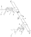
JP5241138B2 - Electrophotographic image forming apparatus - Google Patents

Electrophotographic image forming apparatus Download PDF

Info

Publication number
JP5241138B2
JP5241138B2 JP2007138885A JP2007138885A JP5241138B2 JP 5241138 B2 JP5241138 B2 JP 5241138B2 JP 2007138885 A JP2007138885 A JP 2007138885A JP 2007138885 A JP2007138885 A JP 2007138885A JP 5241138 B2 JP5241138 B2 JP 5241138B2
Authority
JP
Japan
Prior art keywords
tray
image forming
cartridge
forming apparatus
main body
Prior art date
Legal status (The legal status is an assumption and is not a legal conclusion. Google has not performed a legal analysis and makes no representation as to the accuracy of the status listed.)
Expired - Fee Related
Application number
JP2007138885A
Other languages
Japanese (ja)
Other versions
JP2008292804A (en
JP2008292804A5 (en
Inventor
明典 高山
Current Assignee (The listed assignees may be inaccurate. Google has not performed a legal analysis and makes no representation or warranty as to the accuracy of the list.)
Canon Inc
Original Assignee
Canon Inc
Priority date (The priority date is an assumption and is not a legal conclusion. Google has not performed a legal analysis and makes no representation as to the accuracy of the date listed.)
Filing date
Publication date
Application filed by Canon Inc filed Critical Canon Inc
Priority to JP2007138885A priority Critical patent/JP5241138B2/en
Publication of JP2008292804A publication Critical patent/JP2008292804A/en
Publication of JP2008292804A5 publication Critical patent/JP2008292804A5/ja
Application granted granted Critical
Publication of JP5241138B2 publication Critical patent/JP5241138B2/en
Expired - Fee Related legal-status Critical Current
Anticipated expiration legal-status Critical

Links

Images

Landscapes

  • Electrophotography Configuration And Component (AREA)

Description

本発明は、プロセスカートリッジを着脱可能であって、記録媒体に画像を形成するための電子写真画像形成装置に関するものである。   The present invention relates to an electrophotographic image forming apparatus for detachably attaching a process cartridge and forming an image on a recording medium.

ここで、電子写真画像形成装置とは、電子写真画像形成方式を用いて記録媒体に画像を形成するものである。そして、電子写真画像形成装置の例としては、例えば電子写真複写機、電子写真プリンタ(例えばレーザービームプリンタ、LEDプリンタ等)、ファクシミリ装置及びワードプロセッサ等が含まれる。   Here, the electrophotographic image forming apparatus forms an image on a recording medium using an electrophotographic image forming system. Examples of the electrophotographic image forming apparatus include an electrophotographic copying machine, an electrophotographic printer (for example, a laser beam printer, an LED printer, etc.), a facsimile machine, a word processor, and the like.

また、プロセスカートリッジとは、電子写真感光体(像担持体)と、この電子写真感光体に作用する帯電手段・現像手段等のプロセス手段とを一体的にカートリッジ化し、画像形成装置本体に対して着脱可能とするものである。   In addition, the process cartridge is a cartridge in which an electrophotographic photosensitive member (image carrier) and process means such as a charging unit and a developing unit that act on the electrophotographic photosensitive member are integrated into a cartridge so that the image forming apparatus main body It is intended to be detachable.

前記プロセスカートリッジは、使用者自身によって画像形成装置本体に対する着脱を行うことができるから、装置本体のメンテナンスを容易に行うことができるものである。   Since the process cartridge can be attached to and detached from the main body of the image forming apparatus by the user himself, maintenance of the main body of the apparatus can be easily performed.

画像形成装置本体に対するプロセスカートリッジの着脱構成として、中間転写ベルトユニットを引き出し構成とし、カートリッジごと引き出して、カートリッジを着脱する方式がある(特許文献1)。   As a configuration for attaching and detaching the process cartridge to and from the image forming apparatus main body, there is a method in which the intermediate transfer belt unit is a drawer configuration, and the cartridge is pulled out and the cartridge is attached and detached (Patent Document 1).

また、複数のプロセスカートリッジを配列した、インライン方式と呼ばれるものが知られている。このインライン方式の画像形成装置では、イエロー、マゼンタ、シアン、ブラックの各色ごとに、感光体ドラムと現像ユニットを有するプロセスカートリッジを備え、各色の画像を重ね合わせ、フルカラー画像を形成するものである。このような画像形成装置の中には、カートリッジを支持するトレイを設け、画像形成装置から外側にトレイを引き出すことでカートリッジの交換を行うものがある(特許文献2)。
特開2003−316105公報 特開2006−98772公報
Also, what is called an in-line method in which a plurality of process cartridges are arranged is known. This in-line image forming apparatus includes a process cartridge having a photosensitive drum and a developing unit for each color of yellow, magenta, cyan, and black, and superimposes the images of the respective colors to form a full color image. Among such image forming apparatuses, there is a type in which a tray that supports a cartridge is provided and the cartridge is replaced by pulling out the tray from the image forming apparatus (Patent Document 2).
JP 2003-316105 A Japanese Patent Laid-Open No. 2006-98772

本発明は上記の従来技術を更に発展させたものである。   The present invention is a further development of the above prior art.

本発明は、電子写真画像形成装置の内部に必要な空間を減らし、画像形成装置を小型化することを目的としている。   An object of the present invention is to reduce the space required in an electrophotographic image forming apparatus and to reduce the size of the image forming apparatus.

上記目的を達成するための本発明に係る電子写真画像形成装置の代表的な構成は、
記録媒体に画像を形成する電子写真画像形成装置において、
電子写真感光体と、前記電子写真感光体に作用するプロセス手段とを有するプロセスカートリッジを着脱可能に支持する移動部材と、
前記電子写真感光体の表面に形成された画像が転写される転写体と、
位置決め部材と、
前記移動部材を前記電子写真画像形成装置の装置本体の外側に引き出す引き出し位置と、前記移動部材を開口を通過させて前記装置本体の内側に装着する装着位置との間で移動可能に支持する保持部材であって、前記移動部材に支持された前記プロセスカートリッジが有する前記電子写真感光体と前記転写体とを離間させる第一の位置と、前記電子写真感光体と前記転写体とを接触させる第二の位置と、を取りうる保持部材と、
前記移動部材に設けられた被位置決め部であって、前記保持部材が前記第二の位置に位置する際に、前記位置決め部材と係合して、前記移動部材の位置決めをする被位置決め部と、
前記移動部材に設けられた、前記保持部材が前記第一の位置から前記第二の位置に移動する際に、前記位置決め部材と当接して前記被位置決め部を前記位置決め部材と係合する方向に導くガイド部であって、前記被位置決め部よりも前記引き出し位置に近い位置に設けられたガイド部と、
を有することを特徴とする。
A typical configuration of the electrophotographic image forming apparatus according to the present invention for achieving the above object is as follows:
In an electrophotographic image forming apparatus for forming an image on a recording medium,
A moving member that detachably supports a process cartridge having an electrophotographic photosensitive member and process means acting on the electrophotographic photosensitive member;
A transfer body to which an image formed on the surface of the electrophotographic photoreceptor is transferred;
A positioning member ;
Holding that supports the movable member so as to be movable between a pull-out position where the movable member is pulled out to the outside of the main body of the electrophotographic image forming apparatus and a mounting position where the movable member is attached to the inner side of the main body through the opening. A first position for separating the electrophotographic photosensitive member and the transfer member included in the process cartridge supported by the moving member, and a first position for contacting the electrophotographic photosensitive member and the transfer member. A holding member capable of taking two positions;
A portion to be positioned which is provided on said moving member, when the retaining member is positioned at the second position, engages with the positioning member, and a portion to be positioned to the positioning of the moving member,
Wherein provided on the moving member, wherein when the retaining member is moved to said second position from said first position, said positioning member and abutting against engagement with front Symbol position-decided Me member the portion to be positioned A guide portion that guides in a direction to be performed, the guide portion provided at a position closer to the drawing position than the positioned portion;
It is characterized by having.

上記の構成により、保持部材が位置決め部材に位置決めされるために必要な空間を減らして、電子写真画像形成装置を小型化することが可能となる。 With the above configuration, the space required for positioning the holding member on the positioning member can be reduced, and the electrophotographic image forming apparatus can be downsized.

(画像形成装置例の全体的な概略構成)
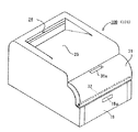
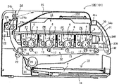
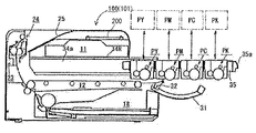
図1は本実施例における電子写真画像形成装置100の外観斜視図、図2は縦断左側面図である。この画像形成装置100は、電子写真プロセスを用いた、4色フルカラーのレーザープリンタである。即ち、パソコン・イメージリーダ・相手方ファクシミリ装置等の外部ホスト装置(不図示)から制御回路部200に入力する電気的な画像信号に基づいて記録媒体(転写材、用紙)に対する画像形成を実行する。
(Overall schematic configuration of image forming apparatus example)
FIG. 1 is an external perspective view of an electrophotographic image forming apparatus 100 in this embodiment, and FIG. 2 is a longitudinal left side view. The image forming apparatus 100 is a four-color full-color laser printer using an electrophotographic process. That is, image formation on a recording medium (transfer material, paper) is executed based on an electrical image signal input to the control circuit unit 200 from an external host device (not shown) such as a personal computer, an image reader, or a counterpart facsimile machine.

以下の説明において、画像形成装置100に関して、前側(正面側)とは、開閉部材としてのドア31を配設した側である。後側とはそれとは反対側である。前後方向とは、画像形成装置100の後側から前側に向かう方向(前方向)と、その逆の方向(後方向)である。左右とは画像形成装置100を前側から見て左又は右である。左右方向とは、右から左に向かう方向(左方向)と、その逆の方向(右方向)である。装置本体(本体フレーム)101とは、プロセスカートリッジ以外の画像形成装置部分である。   In the following description, with respect to the image forming apparatus 100, the front side (front side) is the side on which the door 31 as an opening / closing member is disposed. The rear side is the opposite side. The front-rear direction is a direction from the rear side to the front side of the image forming apparatus 100 (front direction) and the opposite direction (rear direction). Left and right are left or right when the image forming apparatus 100 is viewed from the front side. The left-right direction is a direction from left to right (left direction) and the opposite direction (right direction). The apparatus main body (main body frame) 101 is an image forming apparatus portion other than the process cartridge.

装置本体101内には、後側から前側にかけて、第1から第4の4つのプロセスカートリッジPY・PM・PC・PKを水平方向に並べて配設(インライン構成、タンデム型)してある。各カートリッジは、収容させたトナーの色が異なるだけで、互いに同様の構成のものである。本実施例の各カートリッジは、第1の像担持体としてのドラム型の電子写真感光体(以下、ドラムと記す)1と、このドラムに作用するプロセス手段としての帯電器2・現像器3・クリーニング器4をカートリッジ枠体5内に一体的に組み付けたものである。帯電器2は接触帯電ローラを用いている。現像器3は現像ローラ3aを有し、現像剤容器内には現像剤(トナー)を収容させてある。クリーニング器4はブレード式のものである。   In the apparatus main body 101, the first to fourth process cartridges PY, PM, PC, and PK are arranged in the horizontal direction from the rear side to the front side (in-line configuration, tandem type). The cartridges have the same configuration except that the color of the contained toner is different. Each cartridge of this embodiment includes a drum-type electrophotographic photosensitive member (hereinafter referred to as a drum) 1 as a first image carrier, and a charger 2, a developing device 3, and a process unit that act on the drum. The cleaning device 4 is integrally assembled in the cartridge frame 5. The charger 2 uses a contact charging roller. The developing device 3 has a developing roller 3a, and a developer (toner) is accommodated in the developer container. The cleaning device 4 is of a blade type.

第1のカートリッジPYは、現像器3にイエロー(Y)のトナーを収容させてあり、ドラム1面にY色トナー像を形成する。第2のカートリッジPMは、現像器3にマゼンタ(M)のトナーを収容させてあり、ドラム1面にM色トナー像を形成する。第3のカートリッジPCは、現像器3にシアン(C)のトナーを収容させてあり、ドラム1面にC色トナー像を形成する。第4のカートリッジPKは、現像器3にブラック(K)のトナーを収容させてあり、ドラム1面にK色トナー像を形成する。   The first cartridge PY contains yellow (Y) toner in the developing device 3 and forms a Y-color toner image on the surface of the drum 1. In the second cartridge PM, magenta (M) toner is accommodated in the developing device 3 and an M color toner image is formed on the surface of the drum 1. In the third cartridge PC, cyan (C) toner is accommodated in the developing device 3, and a C color toner image is formed on the surface of the drum 1. The fourth cartridge PK stores black (K) toner in the developing device 3 and forms a K-color toner image on the surface of the drum 1.

カートリッジPY・PM・PC・PKの上方部には、レーザースキャナユニット11が
配設されている。このスキャナユニット11は、外部ホスト装置から制御回路部200に入力する各色の画像情報に対応して変調したレーザー光Lを出力する。その出力レーザー光Lがカートリッジ枠体5の上面に設けた露光窓6を通って各カートリッジ内に進入して、ドラム面のレーザー走査露光がなされる。
A laser scanner unit 11 is disposed above the cartridges PY, PM, PC, and PK. The scanner unit 11 outputs laser light L modulated in accordance with image information of each color input from the external host device to the control circuit unit 200. The output laser light L enters each cartridge through an exposure window 6 provided on the upper surface of the cartridge frame 5, and laser scanning exposure of the drum surface is performed.

カートリッジPY・PM・PC・PKの下方部には、中間転写ベルトユニット12が配設されている。このベルトユニット12は、用紙Pに画像を形成するために、各カートリッジのドラム1と接触する転写体(第2の像担持体)としての、誘電体製で、可撓性を有するエンドレスベルト13を有する。そして、このベルト13を懸回張設して循環移動させる駆動ローラ14・ターンローラ15・テンションローラ16を有する。駆動ローラ14とテンションローラ16は装置本体内の後側に配設してある。ターンローラ15は装置本体内の前側に配設してある。各カートリッジのドラム1は、その下面が、ベルト13の上行側ベルト部分の上面に接している。ベルト13の内側には、上行側ベルト部分を介して各カートリッジのドラム1に対向させて4個の一次転写ローラ17を配設してある。駆動ローラ14には、ベルト13を介して二次転写ローラ22を当接させてある。   An intermediate transfer belt unit 12 is disposed below the cartridges PY, PM, PC, and PK. The belt unit 12 is made of a dielectric and is a flexible endless belt 13 as a transfer body (second image carrier) that contacts the drum 1 of each cartridge in order to form an image on the paper P. Have The belt 13 has a drive roller 14, a turn roller 15, and a tension roller 16 that suspends and stretches the belt 13. The drive roller 14 and the tension roller 16 are disposed on the rear side in the apparatus main body. The turn roller 15 is disposed on the front side in the apparatus main body. The lower surface of the drum 1 of each cartridge is in contact with the upper surface of the ascending belt portion of the belt 13. Four primary transfer rollers 17 are disposed inside the belt 13 so as to face the drum 1 of each cartridge through an ascending belt portion. A secondary transfer roller 22 is brought into contact with the driving roller 14 via a belt 13.

ベルトユニット12の下方部には、給紙ユニット18を配設してある。この給紙ユニット18は、給紙トレイ19、給紙ローラ20、分離パッド21等を有する。給紙トレイ19は装置本体前側から出し入れ自由である(フロントローデング)。19aは給紙トレイ19の前面に設けた指掛け部である。   A paper feeding unit 18 is disposed below the belt unit 12. The sheet feeding unit 18 includes a sheet feeding tray 19, a sheet feeding roller 20, a separation pad 21, and the like. The paper feed tray 19 can be freely inserted and removed from the front side of the apparatus main body (front loading). Reference numeral 19 a denotes a finger hook provided on the front surface of the paper feed tray 19.

装置本体内の後側の上部には、定着装置23と、排紙ローラ対24が配設されている。装置本体の上面は排紙トレイ25にされている。定着装置23は、定着フィルムアセンブリ23aと加圧ローラ23bを有するものを用いている。排紙ローラ対24は排紙ローラ24aと排紙コロ24bである。   A fixing device 23 and a paper discharge roller pair 24 are disposed on the upper rear side in the apparatus main body. The upper surface of the apparatus main body is a paper discharge tray 25. The fixing device 23 has a fixing film assembly 23a and a pressure roller 23b. The paper discharge roller pair 24 is a paper discharge roller 24a and a paper discharge roller 24b.

装置本体内の所定の装着位置(潜像形成位置)に装着されている状態にある各カートリッジは、押圧部材(不図示)により押圧されて所定の位置決め部に固定された状態に保持されている。また、そのカートリッジの駆動入力部53・54(図7)に対して装置本体側の駆動出力部(不図示)が結合している。また、そのカートリッジの電気接点55(図8)に対して装置本体側の給電系統(不図示)が導通化している。   Each cartridge mounted in a predetermined mounting position (latent image forming position) in the apparatus main body is pressed by a pressing member (not shown) and held in a fixed state at a predetermined positioning portion. . Further, a drive output section (not shown) on the apparatus main body side is coupled to the drive input sections 53 and 54 (FIG. 7) of the cartridge. In addition, a power supply system (not shown) on the apparatus body side is electrically connected to the electrical contact 55 (FIG. 8) of the cartridge.

フルカラー画像を形成するための動作は次のとおりである。第1〜第4の各カートリッジPY・PM・PC・PKのドラム1が矢印の反時計方向に所定の制御速度で回転駆動される。ベルト13も矢印の時計方向(ドラム回転に順方向)にドラム1の速度に対応した速度で回転駆動される。スキャナユニット11も駆動される。この駆動に同期して、各カートリッジにおいてそれぞれ所定の制御タイミングで帯電ローラ2がドラム1の表面を所定の極性・電位に一様に帯電する。スキャナユニット11は各ドラム1の表面を各色の画像信号に応じて変調されたレーザー光Lで走査露光する。これにより、各ドラム1の表面に対応色の画像信号に応じた静電潜像が形成される。形成された静電潜像が現像器3によりトナー像として現像される。   The operation for forming a full-color image is as follows. The drums 1 of the first to fourth cartridges PY, PM, PC, and PK are rotationally driven in a counterclockwise direction indicated by arrows at a predetermined control speed. The belt 13 is also rotationally driven at a speed corresponding to the speed of the drum 1 in the clockwise direction of the arrow (forward direction with respect to the drum rotation). The scanner unit 11 is also driven. In synchronization with this drive, the charging roller 2 uniformly charges the surface of the drum 1 to a predetermined polarity and potential at a predetermined control timing in each cartridge. The scanner unit 11 scans and exposes the surface of each drum 1 with a laser beam L modulated in accordance with an image signal of each color. Thereby, an electrostatic latent image corresponding to the image signal of the corresponding color is formed on the surface of each drum 1. The formed electrostatic latent image is developed as a toner image by the developing device 3.

上記のような電子写真画像形成プロセス動作により、第1のカートリッジPYのドラム1にはフルカラー画像のイエロー成分に対応するY色トナー像が形成され、そのトナー像がベルト13上に一次転写される。   By the electrophotographic image forming process operation as described above, a Y toner image corresponding to the yellow component of the full color image is formed on the drum 1 of the first cartridge PY, and the toner image is primarily transferred onto the belt 13. .

第2のカートリッジPMのドラム1にはフルカラー画像のマゼンタ成分に対応するM色トナー像が形成され、そのトナー像が、ベルト13上にすでに転写されているY色トナー像に重畳されて一次転写される。   An M-color toner image corresponding to the magenta component of the full-color image is formed on the drum 1 of the second cartridge PM, and the toner image is superimposed on the Y-color toner image already transferred on the belt 13 for primary transfer. Is done.

第3のカートリッジPCのドラム1にはフルカラー画像のシアン成分に対応するC色トナー像が形成され、そのトナー像が、ベルト13上にすでに転写されているY色+M色トナー像に重畳されて一次転写される。   A C color toner image corresponding to the cyan component of the full color image is formed on the drum 1 of the third cartridge PC, and the toner image is superimposed on the Y color + M color toner image already transferred onto the belt 13. Primary transcription.

第4のカートリッジPCのドラム1にはフルカラー画像のブラック成分に対応するK色トナー像が形成され、そのトナー像が、ベルト13上にすでに転写されているY色+M色+C色トナー像に重畳されて一次転写される。   A K color toner image corresponding to the black component of the full color image is formed on the drum 1 of the fourth cartridge PC, and the toner image is superimposed on the Y color + M color + C color toner image already transferred onto the belt 13. The primary transfer is done.

かくして、ベルト13上にY色+M色+C色+K色の4色フルカラーの未定着トナー像が合成形成される。   In this way, a four-color full-color unfixed toner image of Y color + M color + C color + K color is synthesized and formed on the belt 13.

各カートリッジにおいて、ベルト13に対するトナー像の一次転写後のドラム1面に残留した転写残トナーはクリーニング器4により除去される。   In each cartridge, residual toner remaining on the surface of the drum 1 after the primary transfer of the toner image to the belt 13 is removed by the cleaning device 4.

一方、所定の制御タイミングで給紙ローラ20が駆動される。これにより、給紙ローラ20と分離パッド21との協働で、給紙トレイ19上に積載されている用紙Pが1枚分離給送されて、二次転写ローラ22とベルト13とのニップ部(二次転写ニップ部)に導入される。これにより、用紙Pが該ニップ部を挟持搬送されていく過程でベルト13上の4色重畳のトナー像が用紙Pの面に順次に一括転写される。   On the other hand, the paper feed roller 20 is driven at a predetermined control timing. As a result, the paper P stacked on the paper feed tray 19 is separated and fed by the cooperation of the paper feed roller 20 and the separation pad 21, and the nip portion between the secondary transfer roller 22 and the belt 13. Introduced into the (secondary transfer nip portion). As a result, the four-color superimposed toner image on the belt 13 is sequentially transferred onto the surface of the paper P in a batch as the paper P is nipped and conveyed through the nip portion.

用紙Pはベルト13の面から分離されて定着装置23へ導入され、定着ニップ部で加熱・加圧される。これにより、各色トナー像の混色及び用紙への定着がなされる。そして用紙Pは、定着装置23を出て、フルカラー画像形成物として排紙ローラ対24で排紙トレイ25上に排出される。   The paper P is separated from the surface of the belt 13 and introduced into the fixing device 23, and is heated and pressurized at the fixing nip portion. Thereby, the color toner images are mixed and fixed onto the paper. Then, the paper P exits the fixing device 23 and is discharged onto the paper discharge tray 25 by the paper discharge roller pair 24 as a full-color image formed product.

用紙分離後のベルト13の表面に残留した二次転写残トナーはクリーニング手段(不図示)にて除去される。   The secondary transfer residual toner remaining on the surface of the belt 13 after paper separation is removed by a cleaning means (not shown).

(カートリッジ交換方式)
第1〜第4の各カートリッジPY・PM・PC・PKは、画像形成に使用されるにつれて、それぞれ、現像器3に収容されている現像剤(トナー)が消費される。そして、カートリッジを購入した使用者にとって満足できる品質の画像を形成することが出来なくなる程度まで現像剤が消費された際に、カートリッジとしての商品価値が喪失する。
(Cartridge replacement method)
As each of the first to fourth cartridges PY, PM, PC, and PK is used for image formation, the developer (toner) contained in the developing device 3 is consumed. When the developer is consumed to such an extent that an image with satisfactory quality cannot be formed for the user who purchased the cartridge, the commercial value of the cartridge is lost.

そこで、例えば、個々のカートリッジの現像剤残量を検知する手段(不図示)を具備させて、制御回路部200において、検知残量値を、予め設定したカートリッジ寿命予告や寿命警告のための閾値と比較させる。そして、検知残量値が閾値よりも少ない残量値となったカートリッジについては、表示部(不図示)に、そのカートリッジについての寿命予告あるいは寿命警告を表示させる。これにより使用者に、交換用のカートリッジの準備を促す、あるいはカートリッジの交換を促して、出力画像の品質を維持するようにしている。   Therefore, for example, a means (not shown) for detecting the remaining amount of developer in each cartridge is provided, and the control circuit unit 200 sets the detected remaining amount value to a preset threshold value for cartridge life warning or life warning. Compare with Then, for a cartridge whose detected remaining amount value is smaller than the threshold value, the display unit (not shown) displays a life warning or a life warning for the cartridge. This prompts the user to prepare a cartridge for replacement, or prompts the user to replace the cartridge to maintain the quality of the output image.

本実施例の画像形成装置において、カートリッジの交換は、使用者ビリティ向上のために、カートリッジを引き出し式のトレイに乗せ、フロントアクセスにより交換する方式である。この引き出し式のトレイ35が、カートリッジを着脱可能に支持する。そして、トレイ35は後述するトレイ保持部材34に対して、カートリッジを装置本体101の外側において着脱出来る引き出し位置と、開口部30を通過させて装置本体101の内側に装着する装着位置と、の間を移動できる。   In the image forming apparatus of this embodiment, the cartridge is replaced by a method of placing the cartridge on a pull-out tray and performing front access for improving usability. This pull-out tray 35 supports the cartridge in a detachable manner. The tray 35 is between a drawer position where the cartridge can be attached to and detached from the tray holding member 34, which will be described later, and a mounting position where the cartridge is mounted inside the apparatus main body 101 through the opening 30. Can be moved.

画像形成装置の前面側には、装置本体内へカートリッジを挿入させる、及び、装置本体101からカートリッジを取り出すために、カートリッジを通過させる開口部30が設けられている。その開口部30には、回動可能に設けられ、開口部30を閉鎖する位置と開放する位置とを取り得る開閉部材としてのドア31が配設されている。   On the front side of the image forming apparatus, an opening 30 through which the cartridge passes is provided in order to insert the cartridge into the apparatus main body and to remove the cartridge from the apparatus main body 101. The opening 30 is provided with a door 31 as an opening / closing member that is rotatably provided and can take a position for closing the opening 30 and a position for opening the opening 30.

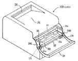
本実施例においては、このドア31は、ドア下辺側に設けた横軸(ヒンジ軸)32を中心に装置本体に対して開閉回動可能である。すなわち、ドア31は、ヒンジ軸32を中心に立て起こし方向に回動して、図1・図2のように、装置本体に対して閉じ込んだ状態にすることができる。このドア31の閉じにより開口部30が閉鎖される。また、ヒンジ軸32を中心に装置本体の手前側に倒し回動して、図3・図4のように、装置本体から開いた状態にすることができる。これにより、装置本体前面の開口部30が大きく開放される。31aはドア31に設けた開閉用指掛け部である。   In the present embodiment, the door 31 can be opened and closed with respect to the apparatus main body about a horizontal axis (hinge axis) 32 provided on the lower side of the door. In other words, the door 31 can be raised from the hinge shaft 32 in the upright direction so as to be closed with respect to the apparatus main body as shown in FIGS. The opening 30 is closed by closing the door 31. Further, it can be tilted and rotated about the hinge shaft 32 toward the front side of the apparatus main body so as to be opened from the apparatus main body as shown in FIGS. As a result, the opening 30 on the front surface of the apparatus main body is largely opened. Reference numeral 31 a denotes an opening / closing finger hook provided on the door 31.

また、装置本体101の骨格となるメインフレーム(図23)の左フレーム80Lの内側と右フレーム80Rの内側には対向させて、前後方向を長手とする左右一対のトレイ保持部材(保持部材)34L・34Rが配設されている。そして、このトレイ保持部材34L・34Rの間には、枠型部材であるカートリッジトレイ35を、前後方向に水平にスライド移動可能に保持させてある。カートリッジPY・PM・PC・PKはこのトレイ35に支持させてある。   Further, a pair of left and right tray holding members (holding members) 34L having a longitudinal direction in the front-rear direction are opposed to the inner side of the left frame 80L and the inner side of the right frame 80R of the main frame (FIG. 23) serving as the skeleton of the apparatus main body 101. -34R is arranged. A cartridge tray 35, which is a frame member, is held between the tray holding members 34L and 34R so as to be slidable horizontally in the front-rear direction. Cartridges PY, PM, PC, and PK are supported on this tray 35.

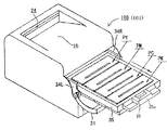
ドア31とトレイ保持部材34L・34Rは後述する連動機構で連結されていて、ドア31の開き回動に連動して、トレイ保持部材34L・34Rが前方向と上方に所定量移動する。即ち、トレイ保持部材34L・34Rが、カートリッジが有するドラム1をベルト13に接触させるための第二の位置から、ドラム1をベルト13から離間させる第一の位置へと移動する。また、ドア31の閉じる動作に連動して、トレイ保持部材34L・34Rが後方向と下方に所定量移動する。即ち、トレイ保持部材34L・34Rが、第一の位置から、第二の位置へと移動する。そして、トレイ保持部材34L・34Rが上記の第二の位置から第一の位置に移動することにより、トレイ保持部材34L・34Rはその前側部が、図3・図4のように、開口部30から装置本体外方に所定量突出した位置に引き出される。   The door 31 and the tray holding members 34L and 34R are connected by an interlocking mechanism which will be described later, and the tray holding members 34L and 34R are moved forward and upward by a predetermined amount in conjunction with the opening rotation of the door 31. That is, the tray holding members 34L and 34R move from the second position for bringing the drum 1 of the cartridge into contact with the belt 13 to the first position for separating the drum 1 from the belt 13. Further, in conjunction with the closing operation of the door 31, the tray holding members 34L and 34R move a predetermined amount backward and downward. That is, the tray holding members 34L and 34R move from the first position to the second position. When the tray holding members 34L and 34R are moved from the second position to the first position, the front sides of the tray holding members 34L and 34R are opened 30 as shown in FIGS. Is pulled out to a position protruding a predetermined amount outward from the apparatus main body.

トレイ保持部材34L・34Rの上記の第二の位置から第一の位置に移動に連動して、各カートリッジPY・PM・PC・PKの駆動入力部に対する装置本体側の駆動出力部の結合が解除された状態になる(駆動解除)。各カートリッジを位置決め固定している押圧部材の押圧が解除される(押圧解除)。各カートリッジの電気接点に対する装置本体側の給電系統の導通が解除される(給電解除)。また、トレイ35を潜像形成位置に固定している、後述する位置決め手段による位置決め固定が解除される。   In conjunction with the movement of the tray holding members 34L and 34R from the second position to the first position, the coupling of the drive output section on the apparatus main body side to the drive input section of each cartridge PY / PM / PC / PK is released. (The drive is released). The pressing of the pressing member that positions and fixes each cartridge is released (press release). The conduction of the power supply system on the apparatus main body side with respect to the electrical contact of each cartridge is released (power supply release). Further, the positioning and fixing by the positioning means described later that fixes the tray 35 at the latent image forming position is released.

トレイ保持部材34L・34Rが第二の位置から第一の位置に移動した状態においては、トレイ保持部材34L・34Rと一緒にトレ35も上方移動して、各カートリッジはドラム1がベルト13から離間した状態になる(図4)。   In a state where the tray holding members 34L and 34R are moved from the second position to the first position, the tray 35 is also moved upward together with the tray holding members 34L and 34R, and the drum 1 is separated from the belt 13 in each cartridge. (Fig. 4).

また、トレイ保持部材34L・34Rが第二の位置から第一の位置に移動した状態時においては、トレイ保持部材34L・34Rに保持されているトレイ35は、後述する仮固定手段により引き出し位置方向への移動がロックされている。   When the tray holding members 34L and 34R are moved from the second position to the first position, the tray 35 held by the tray holding members 34L and 34R is pulled out by the temporary fixing means to be described later. Move to is locked.

そこで、開口部30から露呈しているトレイ前枠片部分に設けた取手部35aを、その内側に配設した移動ロック解除手段としてのロック解除レバー91と共に掴む。この掴みにより、ロック解除レバー91がロック解除方向に回動してトレイ35の移動ロックが解除される。そして、そのトレイ35を、引き出しを開けるように、トレイ保持部材34L・34Rに対して滑走させて前方向に水平にスライド移動させる。これにより、トレイ35を、図5・図6のように、開口部30から装置本体の外側の所定の引き出し位置まで十分に引き出す。   Therefore, the handle portion 35a provided in the tray front frame piece exposed from the opening 30 is gripped together with a lock release lever 91 as a movement lock release means disposed on the inside. By this gripping, the lock release lever 91 rotates in the lock release direction, and the movement lock of the tray 35 is released. Then, the tray 35 is slid with respect to the tray holding members 34L and 34R so as to open the drawer and is slid horizontally in the forward direction. As a result, the tray 35 is sufficiently pulled out from the opening 30 to a predetermined pulling position outside the apparatus main body as shown in FIGS.

そうすると、トレイ35に保持されている第1〜第4の4つカートリッジPY・PM・PC・PKの全体が開口部30を通過して装置本体の外側に露出し、全カートリッジの上面が開放される。トレイ35は、所定の十分量引き出されると、不図示のストッパ部分によりそれ以上の引き出し移動が阻止される。また、トレイ35は、所定の引き出し位置まで水平に引き出されている状態がトレイ保持部材34L・34Rにより保たれる。   Then, the entire first to fourth cartridges PY, PM, PC, and PK held on the tray 35 pass through the opening 30 and are exposed to the outside of the apparatus main body, and the upper surfaces of all the cartridges are opened. The When the tray 35 is pulled out by a predetermined sufficient amount, the tray 35 is prevented from being further pulled out by a stopper portion (not shown). Further, the tray 35 is held by the tray holding members 34L and 34R in a state where the tray 35 is horizontally pulled out to a predetermined pulling position.

トレイ35は、個々のカートリッジを真上に取り出し可能に支持している。また、トレイ35は、個々のカートリッジを真下に向かって移動させることによって支持する。そこで、交換すべき使用済みのカートリッジを、図6の2点鎖線示のように、トレイ35から上方に持ち上げて抜き外す。そして、新しいカートリッジをトレイ35に対して上から嵌め入れて載せる。   The tray 35 supports the individual cartridges so that they can be taken out right above. The tray 35 supports the individual cartridges by moving them downward. Therefore, the used cartridge to be replaced is lifted and removed from the tray 35 as indicated by a two-dot chain line in FIG. Then, a new cartridge is inserted into the tray 35 from above and placed.

この場合、ドラム1の下面を保護する開閉式のドラムカバー(不図示)を有するカートリッジの場合は、トレイ35から外したらカバーを手動で閉じ状態にする。また、新しいカートリッジはトレイ35に乗せる前にカバーを手動で開き状態にする。あるいは、カートリッジをトレイ35から上方に持ち上げて抜き外す過程で、カバーが自動的に閉じ動作する。逆に、トレイ35に上から嵌め入れて載せる過程で、カバーが自動的に開き動作する。   In this case, in the case of a cartridge having an openable drum cover (not shown) for protecting the lower surface of the drum 1, the cover is manually closed after being removed from the tray 35. Also, before the new cartridge is placed on the tray 35, the cover is manually opened. Alternatively, the cover automatically closes in the process of lifting the cartridge upward from the tray 35 and removing it. On the contrary, the cover automatically opens and moves in the process of fitting and placing on the tray 35 from above.

上記において、トレイ35は、カートリッジが有するドラム1の軸線方向とは交差する方向に移動可能に設けられた移動部材である。また、該トレイ35が、前記開口部30を通過してカートリッジを装置本体の外側において着脱出来る引き出し位置と、カートリッジを装置本体の内側に装着するための装着位置と、ドラム1に静電潜像を形成できる潜像形成位置と、を取り得る移動部材である。   In the above, the tray 35 is a moving member provided so as to be movable in a direction crossing the axial direction of the drum 1 included in the cartridge. The tray 35 passes through the opening 30 and can be attached to and detached from the outside of the apparatus main body. The tray 35 can be attached to the inside of the apparatus main body. And a latent image forming position capable of forming a moving member.

また、左右のトレイ保持部材34L・34Rは、移動部材であるトレイ35をカートリッジを着脱出来る引き出し位置に移動する前に、トレイ35を潜像形成位置から上方向に移動させる、及び、潜像形成位置へ向かって下方向に移動させる保持部材である。換言すれば、トレイ保持部材34L・34Rは、トレイ35を支持する支持部材であって、トレイ35を前記引き出し位置と前記装着位置との間で移動させるための第一の位置と、トレイ35を前記潜像形成位置に位置させるための第二の位置とを取り得る。そして、ドア31が閉じるのに連動して、トレイ保持部材34L・34Rは、前記第一の位置から前記第二の位置に移動する。つまり、左右のトレイ保持部材34L・34Rは、トレイ35を転写体であるベルト13に接近する接近方向に沿って移動する保持部材である。   The left and right tray holding members 34L and 34R move the tray 35 upward from the latent image forming position before moving the tray 35, which is a moving member, to the pulling position where the cartridge can be attached and detached. The holding member is moved downward toward the position. In other words, the tray holding members 34L and 34R are support members that support the tray 35, and a first position for moving the tray 35 between the drawing position and the mounting position, and the tray 35. And a second position for positioning at the latent image forming position. In conjunction with the closing of the door 31, the tray holding members 34L and 34R move from the first position to the second position. That is, the left and right tray holding members 34L and 34R are holding members that move the tray 35 along an approaching direction in which the tray 35 approaches the transfer belt 13.

図5・図6のように、トレイ35を引き出し位置に引き出して、交換すべきカートリッジについて交換したら、トレイ35を装置本体内の所定の装着位置まで十分に押し戻し移動して、図3・図4の引き出し前の状態に戻す。   As shown in FIGS. 5 and 6, when the tray 35 is pulled out and the cartridge to be replaced is exchanged, the tray 35 is fully pushed back to a predetermined mounting position in the apparatus main body, and moved to FIGS. Return to the state before pulling out.

トレイ35は、装置本体内の所定の装着位置まで十分に押し戻し移動すると、後述する仮固定手段により装着位置に係止された状態に保持される。   When the tray 35 is sufficiently pushed back and moved to a predetermined mounting position in the apparatus main body, the tray 35 is held in a state of being locked at the mounting position by a temporary fixing means described later.

そして、開かれているドア31を、図1・図2のように、閉じ込む。このドア31の閉じ回動に連動して、トレイ保持部材34L・34Rが後方向と下方に所定量移動(第一の位置から第二の位置へ移動)することで、各カートリッジは潜像形成位置に位置する。そして、このトレイ保持部材34L・34Rの移動に連動して、各カートリッジは押圧部材により押圧されて所定の位置決め部に固定された状態に保持され、各カートリッジのドラム1の下面がベルト13に所定の位置に接触する。そのカートリッジの駆動入力部に対して装置本体側の駆動出力部が結合する。そのカートリッジの電気接点に対して装置本体側の給電系統が導通化する。また、後述する位置決め手段により、トレイ35が潜像形成位置に位置決め固定される。トレイ保持部材34L・34Rが第一の位置から第二の位置へ移動する際に、トレイ35に設けられた後述するガイド面(ガイド部)93dに、ピン軸85が当接する。それによって、ガイド面93dに沿ってトレイ35が、後方向と下方に所定量移動することになる。そして、トレイ保持部材34L・34Rが第二の位置へ移動した際には、ピン軸85に位置決め溝93aが係合してトレイ35が位置決めされる。 (カートリッジ)
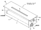
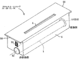
図7と図8はカートリッジの外観斜視図である。図7は駆動側から見た斜視図、図8は非駆動側から見た斜視図である。
Then, the opened door 31 is closed as shown in FIGS. In association with the closing rotation of the door 31, the tray holding members 34L and 34R move a predetermined amount in the rearward and downward directions (from the first position to the second position), whereby each cartridge forms a latent image. Located in position. In conjunction with the movement of the tray holding members 34L and 34R, each cartridge is pressed by the pressing member and held in a fixed state at a predetermined positioning portion, and the lower surface of the drum 1 of each cartridge is fixed to the belt 13 Touch the position. The drive output unit on the apparatus main body side is coupled to the drive input unit of the cartridge. The power supply system on the apparatus body side becomes conductive with respect to the electrical contact of the cartridge. Further, the tray 35 is positioned and fixed at the latent image forming position by positioning means described later. When the tray holding members 34L and 34R move from the first position to the second position, the pin shaft 85 comes into contact with a guide surface (guide portion) 93d (described later) provided on the tray 35. As a result, the tray 35 moves by a predetermined amount along the guide surface 93d in the backward direction and downward. When the tray holding members 34L and 34R move to the second position, the positioning groove 93a engages with the pin shaft 85 and the tray 35 is positioned. (cartridge)
7 and 8 are external perspective views of the cartridge. 7 is a perspective view seen from the driving side, and FIG. 8 is a perspective view seen from the non-driving side.

カートリッジは、ドラム1の軸線方向を左右方向とし、この左右方向を長手とする横長箱型のアセンブリである。ドラム1はカートリッジ枠体5の右側面部(駆動側)と左側面部(非駆動側)に配設した軸受部51・52間に回転可能に支持させて配設してある。右軸受部51にはドラム駆動入力部としてのカップリング嵌合部53を具備させてある。また、右側面部には、現像ローラ3aを駆動するための現像駆動入力部としてのカップリング嵌合部54を具備させてある。また、右側面部には、トレイ35側に設けたカートリッジ回転止め溝35i・93b(図9)に係合する回転止め軸57が設けられている。左側面部には、カートリッジ電気接点55を配設してある。左側面部と右側面部にはカートリッジ枠体5の天井板部分それぞれを左右方向に延長して張り出させて、庇部56を具備させてある。カートリッジ枠体5の上面には左右方向を長手とする露光窓6を設けてある。上記のカートリッジにおいて、カップリング嵌合部53・54を具備させた右側面部が駆動側であり、その反対側の左側面部が非駆動側である。   The cartridge is a horizontally long box type assembly in which the axial direction of the drum 1 is the left-right direction, and the left-right direction is the longitudinal direction. The drum 1 is rotatably supported between bearings 51 and 52 disposed on the right side (drive side) and the left side (non-drive side) of the cartridge frame 5. The right bearing portion 51 is provided with a coupling fitting portion 53 as a drum drive input portion. Further, a coupling fitting portion 54 as a developing drive input portion for driving the developing roller 3a is provided on the right side surface portion. Further, a rotation stop shaft 57 that engages with cartridge rotation stop grooves 35i and 93b (FIG. 9) provided on the tray 35 side is provided on the right side surface portion. A cartridge electrical contact 55 is disposed on the left side surface portion. On the left side surface portion and the right side surface portion, the ceiling plate portions of the cartridge frame 5 are extended and extended in the left-right direction, and a flange portion 56 is provided. On the upper surface of the cartridge frame 5, an exposure window 6 having a longitudinal direction in the left-right direction is provided. In the cartridge described above, the right side surface provided with the coupling fitting portions 53 and 54 is the driving side, and the left side surface on the opposite side is the non-driving side.

(トレイ35)
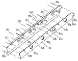
図9はトレイ35を右斜め上から見た外観斜視図、図10はトレイ35を右斜め下から見た外観斜視図である。このトレイ35は、矩形の大枠部を有し、その大枠部内を3枚の仕切り板35fで前後方向に略等分に4つに仕切って、後枠35c側から前枠35b側へ順に、第1〜第4の横長小枠部35(1)〜35(4)を形成させてある。その各小枠部35(1)〜35(4)がそれぞれ第1〜第4の4つカートリッジPY・PM・PC・PKを保持させる部分である。また、各小枠部35(1)〜35(4)の右枠35eには、それぞれ、現像駆動カップリングが出入りする孔部35gを配設してある。
(Tray 35)
FIG. 9 is an external perspective view of the tray 35 as viewed from the upper right, and FIG. 10 is an external perspective view of the tray 35 as viewed from the lower right. The tray 35 has a rectangular large frame portion, and the inside of the large frame portion is divided into four substantially equally in the front-rear direction by three partition plates 35f, and the rear frame 35c side to the front frame 35b side in order. 1st-4th horizontally long small frame part 35 (1)-35 (4) is formed. The small frame portions 35 (1) to 35 (4) are portions for holding the first to fourth cartridges PY, PM, PC, and PK, respectively. Further, the right frame 35e of each of the small frame portions 35 (1) to 35 (4) is provided with a hole portion 35g through which the development drive coupling enters and exits.

また、トレイ35は、カートリッジが有する電気接点55(図8)に電気的に接続する中間電気接点(不図示)を有している。この中間電気接点は装置本体側に設けられた本体側電気接点(不図示)と電気的に接続することが可能である。   Further, the tray 35 has an intermediate electrical contact (not shown) that is electrically connected to an electrical contact 55 (FIG. 8) of the cartridge. This intermediate electrical contact can be electrically connected to a body side electrical contact (not shown) provided on the apparatus body side.

各カートリッジは、トレイ35の対応する小枠部内に上から挿入され、左右側の庇部56の下面がトレイ35の左右枠35d・35eの上面に受け止められことで、トレイ35に乗って支持される。すなわち、トレイ35は、各カートリッジを真上に取り出し可能に支持しており、各カートリッジを真下に向かって移動させることによって支持する。トレイ35は各カートリッジをそれぞれラフに保持している。この構成により、プロセスカートリッジの交換を容易にすることができる。   Each cartridge is inserted into the corresponding small frame portion of the tray 35 from above, and the lower surfaces of the left and right flange portions 56 are received by the upper surfaces of the left and right frames 35d and 35e of the tray 35, thereby being supported on the tray 35. The That is, the tray 35 supports each cartridge so that it can be taken out directly above, and supports each cartridge by moving it downward. The tray 35 holds each cartridge roughly. With this configuration, the process cartridge can be easily replaced.

トレイ35の右枠35eの外面には、トレイ35の補強を行うための補強板金93が取り付けられている。図11はトレイ35の右枠35eと補強板金93との分解斜視図である。補強板金93には、右枠35eに具備させた上記の孔部35gに対応する孔部93gが設けられている。また、補強板金93には、カートリッジの姿勢を保持するカートリッジ回転止め溝93bが設けられている。トレイ35の右枠35eには、補強板金93側の上記の溝93bに対応する溝35iが設けられている。補強板金93の後端部には、トレイ35を装置本体に対して位置決めするための位置決め溝93aが設けられている。トレイ35の右枠35eの外面に設けられたボス35hと、補強板金93側に設けられた穴93cとを嵌合させることにより、補強板金93をトレイ35に対して位置決めさせている。そして、その補強板金93をトレイ35の右枠35eに対してビスや接着剤等の固定手段にて一体に結合させてある。この取り付け状態において、孔部35gと孔部93gが合致対応している。また、溝35iと溝93bが合致対応している。   A reinforcing sheet metal 93 for reinforcing the tray 35 is attached to the outer surface of the right frame 35 e of the tray 35. FIG. 11 is an exploded perspective view of the right frame 35 e of the tray 35 and the reinforcing sheet metal 93. The reinforcing sheet metal 93 is provided with a hole 93g corresponding to the hole 35g provided in the right frame 35e. Further, the reinforcing sheet metal 93 is provided with a cartridge rotation stop groove 93b for holding the posture of the cartridge. The right frame 35e of the tray 35 is provided with a groove 35i corresponding to the groove 93b on the reinforcing sheet metal 93 side. A positioning groove 93 a for positioning the tray 35 with respect to the apparatus main body is provided at the rear end portion of the reinforcing sheet metal 93. The reinforcing sheet metal 93 is positioned with respect to the tray 35 by fitting a boss 35 h provided on the outer surface of the right frame 35 e of the tray 35 and a hole 93 c provided on the reinforcing sheet metal 93 side. The reinforcing sheet metal 93 is integrally coupled to the right frame 35e of the tray 35 by a fixing means such as a screw or an adhesive. In this attached state, the hole portion 35g and the hole portion 93g correspond to each other. Further, the groove 35i and the groove 93b correspond to each other.

位置決め溝93aは、トレイ35が潜像形成位置に位置しているときに、装置本体のメインフレームの右フレーム80Rに設けられていると凸部としてのピン軸85(図23)に嵌合する。これにより、トレイ35の位置が装置本体に対して固定される。上記の位置決め溝93aとピン軸85が、トレイ35を潜像形成位置に固定する位置決め手段である。   When the tray 35 is located at the latent image forming position, the positioning groove 93a is fitted to the pin shaft 85 (FIG. 23) as a convex portion when provided in the right frame 80R of the main frame of the apparatus main body. . Thereby, the position of the tray 35 is fixed with respect to the apparatus main body. The positioning groove 93a and the pin shaft 85 are positioning means for fixing the tray 35 to the latent image forming position.

トレイ35にカートリッジを支持させた状態において、カートリッジ回転止め溝35i・93bと、カートリッジ側の回転止め軸57(図7)とが嵌合する。これにより、カートリッジのドラム1を中心とした回転方向の位置が固定される。   In a state where the cartridge is supported on the tray 35, the cartridge rotation prevention grooves 35i and 93b and the cartridge side rotation prevention shaft 57 (FIG. 7) are fitted. Thereby, the position of the rotation direction around the drum 1 of the cartridge is fixed.

このように、トレイ35の装置本体に対する位置決めと、カートリッジのトレイ35に対する位置決めを1つの板金部材93で行うことにより、カートリッジの姿勢を精度良く保つことが可能となる。   As described above, the positioning of the tray 35 with respect to the apparatus main body and the positioning of the cartridge with respect to the tray 35 are performed by the single sheet metal member 93, whereby the posture of the cartridge can be accurately maintained.

トレイ35の左右枠35d・35eがそれぞれ左右のトレイ保持部材34L・34Rの内側に設けた前後方向のガイド溝部34aに嵌入して係合している。これにより、トレイ35は、左右のトレイ保持部材34L・34R間に支持されるとともに、ガイド溝部34aを滑走してトレイ保持部材に対して前後方向に水平にスライド移動可能である。   The left and right frames 35d and 35e of the tray 35 are fitted into and engaged with front and rear guide groove portions 34a provided inside the left and right tray holding members 34L and 34R, respectively. Thus, the tray 35 is supported between the left and right tray holding members 34L and 34R, and can slide horizontally in the front-rear direction with respect to the tray holding member by sliding along the guide groove 34a.

トレイ35の取手部35aには、トレイ35の仮固定手段としてのロック爪92と、移動ロック解除手段としてのロック解除レバー91と、その連動機構が設けられている。   The handle portion 35a of the tray 35 is provided with a lock claw 92 as a temporary fixing means for the tray 35, a lock release lever 91 as a movement lock release means, and an interlocking mechanism thereof.

トレイ35の仮固定手段は、トレイ保持部材34L・34Rが第一の位置にある場合において、トレイ35が装着位置から引き出し位置に向う方向に移動しないようにトレイを止める手段である。図12は、トレイ35の取手部35aに備えられた、トレイ35の仮固定手段としての被係合部であるロック爪92と、移動ロック解除手段としてのロック解除レバー91と、その連動機構の斜視図である。図13は、ロック爪92が装置本体側の不動のロック部材(係合部)84の係合穴84dに係合している状態を示す断面図である。ロック爪92は、トレイ35の取手部35a側において、下向きに、かつ上下方向に所定のストローク範囲においてスライド移動可能に配設されていて、付勢手段としてのばね95により常時下方へ移動付勢されている。ばね95は、トレイ35に設けたばね受け座35jとロック爪92の上端部との間に縮設してある。取手部35aの内側には、ロック解除レバー91を軸部91aを中心に揺動可能に支持させて配設してある。そして、このレバー91の作用腕部91bをロック爪92に設けた縦長穴92cに係合させてある。レバー91は、自由状態において、ばね95により下方に移動付勢されているロック爪92の縦長穴92cの上端部で作用腕部91bが下方への押圧力を受ける。これにより、レバー91は、軸部91aを中心に反時計方向に、ストッパ部(不図示)で回動止めされるまで回動して、図13のように、取手部35aの内側において起立した回動角状態になっている。また、装置本体側の不動のロック部材(係合部)84には、ロック爪92の下端部が係合する係合穴84dを設けてある。   The temporary fixing means for the tray 35 is a means for stopping the tray so that the tray 35 does not move in the direction from the mounting position toward the pull-out position when the tray holding members 34L and 34R are in the first position. FIG. 12 shows a lock claw 92 which is an engaged portion as a temporary fixing means of the tray 35, a lock release lever 91 as a movement lock release means, and a mechanism for the interlocking mechanism provided in the handle portion 35a of the tray 35. It is a perspective view. FIG. 13 is a sectional view showing a state in which the lock claw 92 is engaged with the engagement hole 84d of the immovable lock member (engagement portion) 84 on the apparatus main body side. The lock claw 92 is slidably disposed on the side of the handle 35a of the tray 35 in a downward and vertical direction within a predetermined stroke range, and is always urged to move downward by a spring 95 as a biasing means. Has been. The spring 95 is contracted between a spring seat 35 j provided on the tray 35 and the upper end of the lock claw 92. Inside the handle portion 35a, a lock release lever 91 is disposed so as to be swingable about a shaft portion 91a. The operating arm portion 91 b of the lever 91 is engaged with a vertically long hole 92 c provided in the lock claw 92. When the lever 91 is in a free state, the working arm portion 91b receives a downward pressing force at the upper end portion of the vertically long hole 92c of the lock claw 92 that is biased to move downward by the spring 95. As a result, the lever 91 rotates counterclockwise around the shaft portion 91a until it is stopped by a stopper portion (not shown), and stands up inside the handle portion 35a as shown in FIG. It is in the rotation angle state. In addition, the stationary lock member (engagement portion) 84 on the apparatus main body side is provided with an engagement hole 84d with which the lower end of the lock claw 92 is engaged.

(ドア31とトレイ保持部材34L・34Rの連動機構)
図14は、ドア31とトレイ保持部材34L・34Rの連動機構部分の斜視図である。ドア31のヒンジ軸32は、装置本体に対して左右方向に水平に配列されている。そして、ヒンジ軸32の左右両端部は、装置本体のメインフレームの左右フレーム80L・80R(図23)間に回転可能に軸受されている。ドア31はこのヒンジ軸32に対して一体に結合されている。したがって、ドア31の開閉回動と一緒にヒンジ軸32も回動する。このヒンジ軸32の左右両端部寄りには、それぞれ、連結アーム37L・37Rが設けられている。アーム37L・37Rは同じ位相でヒンジ軸32に対して一体に結合されている。アーム37L・37Rにはそれぞれ横向き軸37aが設けられている。左側のアーム37Lの横向き軸37aは左側の保持部材34Lの前側下部に具備された縦長孔34bに係合している。また、右側のアーム37Rの横向き軸37aは右側の保持部材34Rの前側下部に具備された縦長孔34bに係合している。
(Linking mechanism of door 31 and tray holding members 34L and 34R)
FIG. 14 is a perspective view of the interlocking mechanism portion between the door 31 and the tray holding members 34L and 34R. The hinge shaft 32 of the door 31 is arranged horizontally in the left-right direction with respect to the apparatus main body. The left and right ends of the hinge shaft 32 are rotatably supported between the left and right frames 80L and 80R (FIG. 23) of the main frame of the apparatus main body. The door 31 is integrally coupled to the hinge shaft 32. Therefore, the hinge shaft 32 also rotates together with the opening / closing rotation of the door 31. Connection arms 37L and 37R are provided near the left and right ends of the hinge shaft 32, respectively. The arms 37L and 37R are integrally coupled to the hinge shaft 32 with the same phase. The arms 37L and 37R are each provided with a lateral shaft 37a. The lateral shaft 37a of the left arm 37L is engaged with a vertically long hole 34b provided in the front lower portion of the left holding member 34L. Further, the lateral shaft 37a of the right arm 37R is engaged with a vertically long hole 34b provided at the front lower portion of the right holding member 34R.

このように、ヒンジ軸32とトレイ保持部材34L・34Rは、アーム37L・37R、横向き軸37a、縦長孔34bを介して連結してある。これにより、ドア31が開閉されると、左右のトレイ保持部材34L・34Rには前後方向への移動力が作用する。   As described above, the hinge shaft 32 and the tray holding members 34L and 34R are connected via the arms 37L and 37R, the lateral shaft 37a, and the vertically long hole 34b. Thereby, when the door 31 is opened and closed, a moving force in the front-rear direction acts on the left and right tray holding members 34L and 34R.

トレイ保持部材34L・34Rは、それぞれ、前後に間隔を開けて植設した2本のピン軸34c(図15)を有する。ピン軸34cは、左右フレーム80L・80Rのそれぞれに設けたカイド穴36に係合されている。上記のピン軸(突起部)34cとカイド穴(穴部)36がトレイ移動規制手段である。このピン軸34cとカイド穴36の係合により、トレイ保持部材34L・34Rはそれぞれ左右フレーム80L・80Rに支持される。   Each of the tray holding members 34L and 34R has two pin shafts 34c (FIG. 15) which are planted with a space in the front and rear direction. The pin shaft 34c is engaged with a guide hole 36 provided in each of the left and right frames 80L and 80R. The pin shaft (projection) 34c and the guide hole (hole) 36 are tray movement restricting means. By the engagement of the pin shaft 34c and the guide hole 36, the tray holding members 34L and 34R are supported by the left and right frames 80L and 80R, respectively.

図15は、右側の保持部材34Rの2本のピン軸34cとカイド穴36を示している。左側の保持部材34Lについては不図示であるけれども、右側の保持部材34Lと同様であり、そのピン軸34cとカイド穴36は右側の保持部材34Lと鏡面対称に構成されている。   FIG. 15 shows the two pin shafts 34c and the guide holes 36 of the right holding member 34R. Although the left holding member 34L is not shown, it is the same as the right holding member 34L, and the pin shaft 34c and the guide hole 36 are configured mirror-symmetrically with the right holding member 34L.

従って、左右のトレイ保持部材34L・34Rは、それぞれ、カイド穴36のガイド範囲において左フレーム80Lと右フレーム80Rに対して移動する自由度がある。   Therefore, the left and right tray holding members 34L and 34R have a degree of freedom to move with respect to the left frame 80L and the right frame 80R in the guide range of the guide hole 36, respectively.

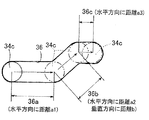
図16はカイド穴36部分の拡大図である。何れのガイド穴36も、前後方向で水平な第1ガイド領域36aと、この第1ガイド領域36aのピン軸前進方向に連設した、昇り傾斜の第2ガイド領域36bを有している。また、何れのガイド穴36も、第2ガイド領域36bの頂上部に連設した、ピン軸34cを受け止めて安定に保持する第3ガイド領域36cを有している。   FIG. 16 is an enlarged view of the guide hole 36 portion. Each of the guide holes 36 includes a first guide region 36a that is horizontal in the front-rear direction, and a second guide region 36b that is continuously inclined in the pin shaft forward direction of the first guide region 36a. Each of the guide holes 36 has a third guide region 36c that is connected to the top of the second guide region 36b and that receives and stably holds the pin shaft 34c.

ピン軸34c、即ちトレイ保持部材34L・34Rは、ドア31が開くのに連動して、第1ガイド領域36aに沿って水平方向に距離a1を移動した後、第2ガイド領域36bに沿って斜め上方に(水平方向に距離a2、垂直方向に距離b)移動する。そして、最後に、トレイ保持部材34L・34Rは第3ガイド領域36cに沿って水平方向に距離a3を移動する。   The pin shaft 34c, that is, the tray holding members 34L and 34R moves in the horizontal direction along the first guide region 36a in conjunction with the opening of the door 31, and then obliquely moves along the second guide region 36b. Move upward (distance a2 in the horizontal direction and distance b in the vertical direction). Finally, the tray holding members 34L and 34R move a distance a3 in the horizontal direction along the third guide region 36c.

(トレイ35の仮固定手段と位置決め手段の動作)
トレイ35の仮固定手段と位置決め手段の動作を、図15、図17〜図22により説明する。図17の(a)〜(d)及び図18の(a)〜(d)はそれぞれ図15の(a)〜(d)に対応しており、図15の(a)〜(d)におけるトレイ35のロック爪92と位置決め溝93aの周辺の部分的拡大図である。
(Operation of temporary fixing means and positioning means of tray 35)
The operation of the temporary fixing means and positioning means for the tray 35 will be described with reference to FIGS. 15 and 17 to 22. (A) to (d) in FIG. 17 and (a) to (d) in FIG. 18 correspond to (a) to (d) in FIG. 15 respectively, and in (a) to (d) in FIG. 4 is a partially enlarged view of the periphery of a lock claw 92 and a positioning groove 93a of the tray 35. FIG.

1)図15の(a)は、ドア31が装置本体に対して所定の閉じ位置に十分に閉められている状態時を示している。 1) FIG. 15A shows a state in which the door 31 is sufficiently closed at a predetermined closed position with respect to the apparatus main body.

この状態時においては、左右のトレイ保持部材34L・34Rは、ヒンジ軸32、連結アーム37L・37R、横向き軸37a、縦長孔34bを介して装置本体内の後方向へ移動されている。ピン軸34cはガイド穴36の第1ガイド領域36aの後端部に位置している。そのために、左右のトレイ保持部材34L・34Rは、それぞれ、左フレーム80Lと右フレーム80Rとに対して所定の下げ位置(第二の位置)に保持されている。従って、トレイ保持部材34L・34Rに保持させてあるトレイ35も所定の下げ位置(潜像形成位置)に保持されている。   In this state, the left and right tray holding members 34L and 34R are moved rearward in the apparatus main body via the hinge shaft 32, the connecting arms 37L and 37R, the lateral shaft 37a, and the vertically long hole 34b. The pin shaft 34 c is located at the rear end portion of the first guide region 36 a of the guide hole 36. Therefore, the left and right tray holding members 34L and 34R are held at predetermined lowered positions (second positions) with respect to the left frame 80L and the right frame 80R, respectively. Accordingly, the tray 35 held by the tray holding members 34L and 34R is also held at a predetermined lowered position (latent image forming position).

トレイ35に保持されている各カートリッジPY・PM・PC・PKは、それぞれ左右側の上面部分が押圧部材(不図示)により押圧されている。これにより、駆動側の軸受部51と非駆動側の軸受部52との下面部分(被位置決め部)が、装置本体のステー部材40(図23:内側板)に設けられた位置決め部41に固定されて、各カートリッジが装置本体に対して所定に位置決め状態に保持される。この状態において、各カートリッジのドラム下面がベルトユニット12のベルト13の上行側ベルト部分の上面に対して所定に安定に接している。   Each cartridge PY, PM, PC, and PK held on the tray 35 is pressed by the pressing member (not shown) on the upper surface portion on the left and right sides. As a result, the lower surface portions (positioned portions) of the driving-side bearing portion 51 and the non-driving-side bearing portion 52 are fixed to the positioning portion 41 provided on the stay member 40 (FIG. 23: inner plate) of the apparatus main body. Thus, each cartridge is held in a predetermined positioning state with respect to the apparatus main body. In this state, the drum lower surface of each cartridge is in contact with the upper surface of the ascending belt portion of the belt 13 of the belt unit 12 in a predetermined and stable manner.

各カートリッジのカップリング嵌合部53・54には、それぞれ、装置本体側のドラム駆動カップリング(不図示)と現像駆動カップリング(不図示)が嵌入している状態にある。各カートリッジの電気接点に対して装置本体側の給電系統が導通化している。   A drum drive coupling (not shown) and a development drive coupling (not shown) on the apparatus main body side are fitted in the coupling fitting portions 53 and 54 of each cartridge. The power supply system on the apparatus main body side is electrically connected to the electrical contact of each cartridge.

また、図18の(a)のように、トレイ35の位置決め手段である位置決め溝93aは装置本体の右フレーム80Rに設けたピン軸85と嵌合している。これにより、トレイ35の水平方向の位置が固定されている。即ち、トレイ35は潜像形成位置に固定されている。   Further, as shown in FIG. 18A, a positioning groove 93a which is a positioning means of the tray 35 is fitted with a pin shaft 85 provided in the right frame 80R of the apparatus main body. Thereby, the horizontal position of the tray 35 is fixed. That is, the tray 35 is fixed at the latent image forming position.

また、図17の(a)、図13のように、トレイ35の仮固定手段であるロック爪92は、その下端部が、装置本体側の不動のロック部材84の係合穴84dに係合している。この係合状態においては、ロック爪92とロック部材84の突き当て面84aは離間した状態となっている。   Further, as shown in FIGS. 17A and 13, the lock claw 92 that is a temporary fixing means of the tray 35 is engaged at its lower end portion with the engagement hole 84 d of the immovable lock member 84 on the apparatus main body side. doing. In this engaged state, the lock claw 92 and the abutting surface 84a of the lock member 84 are in a separated state.

2)図15の(b)は、ドア31を途中まで開いた状態時を示している。図15の(a)のドア閉じ状態からドア31が開かれていくと、これに連動して、左右のトレイ保持部材34L・34Rは装置本体内を前方向に引かれる。これにより、トレイ保持部材34L・34Rは、ピン軸34cが、カイド穴36の第1ガイド領域36aでガイドされて、先ず水平方向に距離a1を前方向に移動する。図15の(b)はこの状態時を示している。   2) FIG. 15B shows a state in which the door 31 is partially opened. When the door 31 is opened from the door closed state of FIG. 15A, the left and right tray holding members 34L and 34R are pulled forward in the apparatus main body in conjunction with this. As a result, the pin holding shaft 34c of the tray holding members 34L and 34R is guided by the first guide region 36a of the guide hole 36, and first moves the distance a1 forward in the horizontal direction. FIG. 15B shows this state.

このトレイ保持部材34L・34Rの距離a1の移動過程において、各カートリッジに対するドラム駆動カップリングと、現像駆動カップリングが解除される。また各カートリッジの押圧部材による押圧位置決めも解除される。   In the process of moving the tray holding members 34L and 34R by the distance a1, the drum drive coupling and the development drive coupling for each cartridge are released. Further, the pressing positioning by the pressing member of each cartridge is also released.

この状態時も、図18の(b)(=図18の(a))のように、トレイ35の位置決め溝93aが右フレーム80Rに設けたピン軸85と嵌合していて、トレイ35の水平方向の位置が固定されている。そのため、トレイ35がトレイ保持部材34L・34Rの前方向への動きに追従することはない。   Also in this state, as shown in FIG. 18B (= FIG. 18A), the positioning groove 93a of the tray 35 is fitted to the pin shaft 85 provided in the right frame 80R, and the tray 35 The horizontal position is fixed. Therefore, the tray 35 does not follow the forward movement of the tray holding members 34L and 34R.

また、トレイ35に動きはないから、ロック爪92は、図17の(b)のように、その下端部が、装置本体側の不動のロック部材84の係合穴84dに係合している。この係合状態は、図17の(a)の係合状態と同様である。   Since the tray 35 does not move, the lower end portion of the lock claw 92 is engaged with the engagement hole 84d of the immovable lock member 84 on the apparatus main body side as shown in FIG. . This engagement state is the same as the engagement state of FIG.

3)図15の(c)は、図15の(b)の状態から、さらにドア31を開いた状態時を示している。   3) FIG. 15C shows a state in which the door 31 is further opened from the state of FIG. 15B.

ドア31の引続く開き回動に連動して、トレイ保持部材34L・34Rは更に装置本体内を前方向に引かれる。これにより、トレイ保持部材34L・34Rは、ピン軸34cがカイド穴36の第2ガイド領域36bでガイドされて、斜め前上方に移動していく。このトレイ保持部材34L・34Rの斜め前上方への移動過程において、各カートリッジの電気接点55と装置本体側との電気的接続が解除される。   The tray holding members 34L and 34R are further pulled forward in the apparatus main body in conjunction with the subsequent opening and turning of the door 31. As a result, the tray holding members 34L and 34R move obliquely forward and upward with the pin shaft 34c being guided by the second guide region 36b of the guide hole 36. In the process of moving the tray holding members 34L and 34R obliquely forward and upward, the electrical connection between the electrical contact 55 of each cartridge and the apparatus main body is released.

ここで、図18の(a)のように、右フレーム80Rに設けたピン軸85の中心が位置決め溝93aに進入する量をc、ピン軸85の上端部と位置決め溝93aの下端部の距離をdとする。また、トレイ35を保持しているトレイ保持部材34L・34Rの上記の斜め上方移動にともなうトレイ35の上昇量をbとする。トレイ保持部材34L・34Rが斜め上方に移動する際、トレイ35の位置決め溝93aがピン軸85に係合している間(c>b)は、トレイ35はトレイ保持部材34L・34Rの垂直方向の移動にのみ追従する。したがって、トレイ35に保持されている各カートリッジPY・PM・PC・PKのドラム下面がベルト13に接している状態ではトレイ35が水平方向に移動することはなく、ドラム1とベルト13のこすれによって生じるキズ、メモリを防止することができる。   Here, as shown in FIG. 18A, the amount by which the center of the pin shaft 85 provided in the right frame 80R enters the positioning groove 93a is c, and the distance between the upper end portion of the pin shaft 85 and the lower end portion of the positioning groove 93a. Is d. Further, b is the amount by which the tray 35 is lifted as the tray holding members 34L and 34R holding the tray 35 move obliquely upward. When the tray holding members 34L and 34R move obliquely upward, the tray 35 is perpendicular to the tray holding members 34L and 34R while the positioning groove 93a of the tray 35 is engaged with the pin shaft 85 (c> b). Follow the movement only. Accordingly, the tray 35 does not move in the horizontal direction when the drum lower surface of each cartridge PY / PM / PC / PK held on the tray 35 is in contact with the belt 13, and the drum 1 and the belt 13 are rubbed. Scratches and memory can be prevented.

そして、トレイ保持部材34L・34Rがある程度持ち上がった状態(c≦b)で、図18の(c)のように、ピン軸85が位置決め溝93aから抜け、トレイ35の水平方向の位置決めが解除される。このとき、図17の(c)のように、トレイ35のロック爪92に設けた上向き傾斜面92bとロック部材84の係合穴84dに設けた下向き傾斜面84bが当接する。   Then, in a state where the tray holding members 34L and 34R are lifted to some extent (c ≦ b), as shown in FIG. 18C, the pin shaft 85 comes out of the positioning groove 93a, and the horizontal positioning of the tray 35 is released. The At this time, as shown in FIG. 17C, the upward inclined surface 92b provided in the lock claw 92 of the tray 35 and the downward inclined surface 84b provided in the engagement hole 84d of the lock member 84 abut.

さらにドア31を開くと、トレイ保持部材34L・34Rは引き続き斜め前上方へ移動する。このとき、ロック爪92とロック部材84の係合穴84dとが当接している傾斜面92b・84bのカム作用によって傾斜面に沿って、トレイ35が斜め後ろ上方へ移動する。   When the door 31 is further opened, the tray holding members 34L and 34R continue to move obliquely forward and upward. At this time, the tray 35 moves obliquely rearward and upward along the inclined surface by the cam action of the inclined surfaces 92b and 84b in which the lock claw 92 and the engagement hole 84d of the lock member 84 are in contact with each other.

トレイ35を上方に移動した後、本体前方向に引き出すためには、位置決め溝93aの下端部がピン軸85の上端部を乗り越える必要がある。したがって、第2ガイド領域36bによるトレイ保持部材34L・34Rの上昇量bは、位置決め溝93aの下端部がピン軸85の上端部との距離dより大きくする必要がある。   After the tray 35 is moved upward, the lower end portion of the positioning groove 93a needs to get over the upper end portion of the pin shaft 85 in order to pull it out in the front direction of the main body. Therefore, the amount b of the tray holding members 34L and 34R raised by the second guide region 36b needs to be larger than the distance d between the lower end portion of the positioning groove 93a and the upper end portion of the pin shaft 85.

4)図15の(d)は、ドア31が所定の開き位置に十分に開かれた状態時を示している。 4) (d) of FIG. 15 shows a state in which the door 31 is sufficiently opened at a predetermined opening position .

この状態時においては、トレイ保持部材34L・34Rは第2ガイド領域36bによる斜め前上方移動を終えて、ピン軸34cが水平の第3ガイド領域36cに位置している。即ち、トレイ保持部材34L・34Rは斜め上方に移動に移動した後に水平方向に移動する。これは、その後、トレイ保持部材34L・34Rからトレイ35を引き出してカートリッジを交換する際に、カートリッジやトレイ保持部材の高さ方向の位置を安定させるためと、トレイ保持部材が元に戻ろうとする動きを防止するためである。   In this state, the tray holding members 34L and 34R have finished moving diagonally forward and upward by the second guide region 36b, and the pin shaft 34c is positioned in the horizontal third guide region 36c. That is, the tray holding members 34L and 34R move in the horizontal direction after moving obliquely upward. Thereafter, when the tray 35 is pulled out from the tray holding members 34L and 34R and the cartridge is replaced, the tray holding member tries to return to the original position in order to stabilize the position of the cartridge and the tray holding member in the height direction. This is to prevent movement.

ドア31が所定の開き位置に十分に開かれることにより、トレイ保持部材34L・34Rは第二の位置から第一の位置に移動した状態になる。この状態においては、トレイ保持部材34L・34Rと一緒にトレ35も上方移動して、各カートリッジはドラム1がベルト13から非接触に離間した状態になる(図4)。 When the door 31 is sufficiently opened at the predetermined opening position , the tray holding members 34L and 34R are moved from the second position to the first position. In this state, the tray 35 moves upward together with the tray holding members 34L and 34R, and each cartridge is in a state in which the drum 1 is separated from the belt 13 in a non-contact manner (FIG. 4).

また、図15の(d)の状態においては、図17の(d)、図19のように、ロック爪92の突き当て面92aとロック部材84の係合穴84dの突き当て面84aが当接している。即ち、トレイ保持部材34L・34Rが第二の位置から第一の位置に移動した状態時においては、トレイ保持部材34L・34Rに保持されているトレイ35は、ロック爪92により装着位置から引き出し位置に向って移動しないように移動規制されている。   Further, in the state of FIG. 15D, as shown in FIG. 17D and FIG. 19, the abutting surface 92a of the lock claw 92 and the abutting surface 84a of the engagement hole 84d of the lock member 84 are in contact with each other. Touching. That is, when the tray holding members 34L and 34R are moved from the second position to the first position, the tray 35 held by the tray holding members 34L and 34R is pulled out from the mounting position by the lock claw 92. The movement is restricted so that it does not move toward.

そこで使用者は、開口部30から露呈しているトレイ35の取手部35aを、その内側に配設したロック解除レバー91と共に掴む。この掴みにより、レバー91が、図20のように、軸部91aを中心に時計方向(ロック解除方向)に回動する。このレバー91の回動により、ロック爪92がばね95の押し下げ力に抗して持ち上げられて上下へ移動する。これにより、ロック爪92の下端部が係合穴84aから抜け出て、トレイ35の移動ロックが解除される。このロック解除されたトレイ35を、引き出しを開けるように、トレイ保持部材34L・34Rに対して滑走させて前方向に水平にスライド移動させる。これにより、トレイ35を、図5・図6のように、開口部30から装置本体の外側の所定の引き出し位置まで十分に引き出す。   Therefore, the user grasps the handle portion 35a of the tray 35 exposed from the opening 30 together with the lock release lever 91 disposed on the inside thereof. By this gripping, the lever 91 rotates clockwise (unlock direction) about the shaft portion 91a as shown in FIG. By the rotation of the lever 91, the lock claw 92 is lifted against the pressing force of the spring 95 and moved up and down. As a result, the lower end of the lock claw 92 comes out of the engagement hole 84a, and the movement lock of the tray 35 is released. The unlocked tray 35 is slid horizontally with respect to the tray holding members 34L and 34R so as to open the drawer and horizontally moved forward. As a result, the tray 35 is sufficiently pulled out from the opening 30 to a predetermined pulling position outside the apparatus main body as shown in FIGS.

5)図5・図6のように、トレイ35を引き出し位置に引き出して、交換すべきカートリッジについて交換したら、トレイ35を装置本体内の装着位置まで十分に押し戻して移動して、図3・図4の引き出し前の状態に戻す。   5) As shown in FIGS. 5 and 6, when the tray 35 is pulled out and the cartridge to be replaced is exchanged, the tray 35 is fully pushed back to the mounting position in the apparatus main body and moved. Return to the state before 4 was pulled out.

押し戻し移動されたトレイ35が装着位置に戻る前時点において、図21のように、ロック爪92の下端部に具備させた下向き斜面部92cが、ロック部材84に設けた上向き斜面部84cに当接する。更に、トレイ35を、押し戻し移動すると、斜面部92d・84cとのカム作用により、ロック爪92がばね95に抗して上方に移動して、図22のように、ロック部材84の上面に乗り上がる。その後も引き続き、トレイ35を、十分に押し戻し移動する。そうすると、ロック爪92がロック部材84の係合穴84aに対応位置し、ばね95による下方へ移動する。これにより、ロック部材84の下端部が係合穴84aに嵌り込んで係合して、図19のロック状態に戻る。   Before the tray 35 that has been pushed back returns to the mounting position, the downward slope 92c provided at the lower end of the lock claw 92 contacts the upward slope 84c provided on the lock member 84 as shown in FIG. . Further, when the tray 35 is moved back, the lock claw 92 moves upward against the spring 95 due to the cam action with the slope portions 92d and 84c, and rides on the upper surface of the lock member 84 as shown in FIG. Go up. Subsequently, the tray 35 is sufficiently pushed back and moved. Then, the lock claw 92 is positioned corresponding to the engagement hole 84 a of the lock member 84 and moves downward by the spring 95. As a result, the lower end portion of the lock member 84 is fitted into the engagement hole 84a and engaged, and the locked state shown in FIG. 19 is restored.

そして、ドア31を閉じ込むことで、トレイ保持部材34L・34Rが第一の位置から第二の位置に移動して、トレイ35が、図15のように、潜像形成位置に移動され、画像形成装置が画像形成動作可能な状態になる。   Then, by closing the door 31, the tray holding members 34L and 34R are moved from the first position to the second position, and the tray 35 is moved to the latent image forming position as shown in FIG. The forming apparatus is ready for an image forming operation.

即ち、図15の(d)の状態から、ドア31を閉じていく過程においては、まずトレイ保持部材34L・34Rが第3ガイド領域36cによって水平方向に移動した後、第2ガイド領域36bによって斜め後ろ下方に移動する(図15の(c))。このとき、図18の(c)のように、補強板金93の下向き傾斜面(移動部材に設けたガイド部)93dと、右フレーム(不動部材)80Rに設けたピン軸(凸部)85とが当接し、該補強板金93の傾斜面93dに沿ってトレイ35は斜め前下方に移動する。さらにドア31を閉じると、補強板金93の位置決め溝93aとピン軸85とが嵌合し、トレイ35の水平方向の位置が固定され、引き続きドア31を閉じるとトレイ35は垂直方向にのみ移動し、図15の(b)(=図15の(a))の状態となる。   That is, in the process of closing the door 31 from the state of FIG. 15 (d), the tray holding members 34L and 34R are first moved in the horizontal direction by the third guide region 36c and then obliquely moved by the second guide region 36b. It moves backward and downward ((c) of FIG. 15). At this time, as shown in FIG. 18 (c), the downward inclined surface (guide portion provided on the moving member) 93d of the reinforcing sheet metal 93 and the pin shaft (convex portion) 85 provided on the right frame (non-moving member) 80R Come into contact with each other, and the tray 35 moves obliquely forward and downward along the inclined surface 93 d of the reinforcing sheet metal 93. When the door 31 is further closed, the positioning groove 93a of the reinforcing sheet metal 93 and the pin shaft 85 are fitted to fix the horizontal position of the tray 35. When the door 31 is subsequently closed, the tray 35 moves only in the vertical direction. 15 (b) (= FIG. 15 (a)).

また、ロック爪92は、ロック部材84の係合穴84aに対する係合状態が、図17の(d)から(c)を経て(b)=(a)の係合状態に移行する。   Further, in the lock claw 92, the engagement state of the lock member 84 with respect to the engagement hole 84a shifts from (d) to (c) in FIG. 17 to the engagement state (b) = (a).

上記において、補強板金93の傾斜面93dと右フレーム80Rのピン軸85が、移動部材であるトレイ35の水平方向の移動をガイドするガイド手段となっている。このガイド手段は、移動部材35に設けたガイド面(ガイド形状)93dと、装置本体の不動部材80Rに設けた凸部85により構成される。そして、保持部材34L・34により移動部材35が前記近接方向に移動する際に、凸部85がガイド面93dを押すことにより、移動部材35が引き出し位置と異なる方向に移動する。   In the above, the inclined surface 93d of the reinforcing sheet metal 93 and the pin shaft 85 of the right frame 80R serve as guide means for guiding the horizontal movement of the tray 35 as a moving member. The guide means includes a guide surface (guide shape) 93d provided on the moving member 35 and a convex portion 85 provided on the stationary member 80R of the apparatus main body. Then, when the moving member 35 moves in the proximity direction by the holding members 34L and 34, the convex portion 85 presses the guide surface 93d, so that the moving member 35 moves in a direction different from the pulling position.

即ち、このガイド手段は、保持部材34L・34Rにより移動部材35を前記近接方向に沿って移動する際に、前記近接方向と直交する方向に前記移動部材を移動させる。そして、移動部材35の前記近接方向の移動にとなって、前記近接方向とほぼ直交(直交及び実質的の直交を含む:以下、同じ)する方向に保持部材34L・34Rが移動する。   In other words, the guide means moves the moving member in a direction orthogonal to the proximity direction when the moving member 35 is moved along the proximity direction by the holding members 34L and 34R. Then, the movement of the moving member 35 in the proximity direction causes the holding members 34L and 34R to move in a direction that is substantially orthogonal to the proximity direction (including orthogonal and substantially orthogonal; hereinafter the same).

また、移動部材35が引き出し位置と潜像形成位置との間を移動する途中で、移動部材35を一時的に固定する仮固定手段であるロック爪92とロック部材84が、移動部材35の水平方向の移動をガイドするガイド手段となっている。即ち、仮固定手段92・84がガイド手段を兼ねる。   Further, while the moving member 35 is moving between the pull-out position and the latent image forming position, the lock claw 92 and the lock member 84 which are temporary fixing means for temporarily fixing the moving member 35 are disposed horizontally with respect to the moving member 35. It serves as a guide means for guiding the movement in the direction. That is, the temporary fixing means 92 and 84 also serve as guide means.

そして、保持部材であるトレイ保持部材34L・34Rのドラム1とベルト13が接触する方向成分の移動に追従してトレイ35が上下方向に移動する。これと同時に、ガイド手段93・85及び92・84がトレイ35をトレイ保持部材34L・34Rに対して水平方向に移動するようガイドする。これにより、トレイ35は斜め後ろ上方(ドア開き回転時)及び斜め前下方(ドア閉じ回転時)に移動する。   Then, the tray 35 moves up and down following the movement of the direction component in which the drum 1 and the belt 13 of the tray holding members 34L and 34R that are holding members contact. At the same time, the guide means 93, 85 and 92, 84 guide the tray 35 to move in the horizontal direction with respect to the tray holding members 34L, 34R. As a result, the tray 35 moves obliquely rearward and upward (during door opening rotation) and diagonally forward and downward (during door closing rotation).

上記のような構成を用いることにより、下記の効果が得られる。即ち、ロック爪92により固定されたトレイ35の水平方向の位置が部品寸法のばらつきや環境変動により変化した場合であっても、右フレーム80Rのピン軸85は、補強板金93の傾斜面93dに沿って、確実に位置決め溝93aに嵌合させることが可能となる。   By using the configuration as described above, the following effects can be obtained. That is, even when the horizontal position of the tray 35 fixed by the lock claw 92 is changed due to variations in component dimensions or environmental fluctuations, the pin shaft 85 of the right frame 80R is placed on the inclined surface 93d of the reinforcing sheet metal 93. Accordingly, it is possible to reliably fit the positioning groove 93a.

また、位置決め溝93aの装置本体後ろ側に傾斜面を設ける必要が無いため、補強板金93がピン軸85を乗り越えるためにトレイ35を上昇させる高さを最小限に抑えることができる。これにより、装置本体内部に必要な空間を減らすことが可能となり、画像形成装置の高さを低くすることができる。   In addition, since it is not necessary to provide an inclined surface on the rear side of the apparatus main body of the positioning groove 93a, the height at which the tray 35 is raised in order for the reinforcing sheet metal 93 to get over the pin shaft 85 can be minimized. As a result, it is possible to reduce the space required inside the apparatus main body, and to reduce the height of the image forming apparatus.

本実施例において、移動部材35を装置本体に固定する位置決め手段は、移動部材35に設けた溝93aと、装置本体に設けた不動のピン軸85としているが、移動部材35にピン軸等の凸部を設け、装置本体側に溝等を設けても良い。   In this embodiment, the positioning means for fixing the moving member 35 to the apparatus main body is the groove 93a provided in the moving member 35 and the stationary pin shaft 85 provided in the apparatus main body. A convex portion may be provided, and a groove or the like may be provided on the apparatus main body side.

ガイド手段は、移動部材35側に設けた凸部と、不動部材80L側に設けたガイド面により構成することもできる。そして、保持部材34L・34Rにより移動部材35が前記近接方向に移動する際に、前記凸部が前記ガイド面に押されることにより、移動部材35が前記引き出し位置と異なる方向に移動する。   The guide means can also be configured by a convex portion provided on the moving member 35 side and a guide surface provided on the stationary member 80L side. When the moving member 35 moves in the proximity direction by the holding members 34L and 34R, the moving member 35 moves in a direction different from the pull-out position by the convex portion being pushed by the guide surface.

上記のガイド手段により、カートリッジを支持する移動部材が、引き出し位置から、潜像形成を行うために転写体と近接する近接方向に移動する際に、前記近接方向と略直交する方向に移動部材を移動させることが可能となる。   When the moving member that supports the cartridge moves from the pull-out position in the proximity direction close to the transfer body to form a latent image, the moving member is moved in a direction substantially orthogonal to the proximity direction. It can be moved.

以上説明したように、前記近接方向に沿って移動部材35が移動する移動量を最小限に抑えることにより、画像形成装置の内部に必要な空間を減らし、画像形成装置を小型化することが可能となる。   As described above, by minimizing the amount of movement of the moving member 35 along the proximity direction, it is possible to reduce the space required inside the image forming apparatus and to reduce the size of the image forming apparatus. It becomes.

移動部材35が前記近接方向に移動する際に、部品寸法のばらつきや環境変動による部品の変形が生じた場合であっても、位置決め手段により確実に位置決めされるようにガイドするガイド面を設ける。そのガイド面は、位置決め手段より引き出し位置に近い側或いは遠い側のいずれかに設ければ良くなる。   When the moving member 35 moves in the proximity direction, a guide surface is provided to guide the positioning so as to be surely positioned by the positioning means even when the parts are deformed due to variations in part dimensions or environmental fluctuations. The guide surface may be provided on either the side closer to or far from the pulling position than the positioning means.

即ち、移動部材35にガイド面を設ける場合には、位置決め手段より引き出し位置又は開口部30に近い側にガイド面を設ければ、このガイド面に沿って移動部材35を移動させることにより確実に位置決めを行うことができる。また、装置本体の不動部材にガイド面を設ける場合には位置決め手段より引き出し位置又は開口部30に遠い側にガイド面を設ければ、このガイド面に沿って移動部材35を移動させることにより確実に位置決めを行うことができる。   That is, when the guide surface is provided on the moving member 35, if the guide surface is provided on the side closer to the drawing position or the opening 30 than the positioning means, the moving member 35 can be reliably moved along the guide surface. Positioning can be performed. Further, when the guide surface is provided on the stationary member of the apparatus main body, if the guide surface is provided on the side farther from the positioning unit than the drawing position or the opening 30, the moving member 35 is moved along the guide surface. Can be positioned.

つまり、トレイ35がベルト13と直行する方向に移動する際に、ベルト13と平行な方向にトレイ35が移動する保持部材を設け、トレイ位置決めのガイドを位置決めの前側或いは後ろ側の片方にする。   That is, when the tray 35 moves in a direction perpendicular to the belt 13, a holding member is provided to move the tray 35 in a direction parallel to the belt 13, and the tray positioning guide is set to one of the front side and the rear side of the positioning.

これにより、移動部材が位置決め手段を乗り越えて引き出し位置と潜像形成位置との間を移動するために、移動部材を前記近接方向に移動させる移動量を最小限に抑えることができ、画像形成装置本体を小型化することが可能となる。   Accordingly, since the moving member moves over the positioning means and moves between the drawing position and the latent image forming position, the moving amount of moving the moving member in the proximity direction can be minimized, and the image forming apparatus The main body can be downsized.

実施例の画像形成装置の外観斜視図External perspective view of image forming apparatus of embodiment その画像形成装置の縦断左側面図Longitudinal left side view of the image forming apparatus ドアを開いた状態の画像形成装置の外観斜視図External perspective view of image forming apparatus with door open その画像形成装置の縦断左側面図Longitudinal left side view of the image forming apparatus 図3の状態から更にトレイを引き出した状態の画像形成装置の外観斜視図FIG. 3 is an external perspective view of the image forming apparatus in a state where the tray is further pulled out from the state of FIG. 図4の状態から更にトレイを引き出した状態の画像形成装置の外観斜視図FIG. 4 is an external perspective view of the image forming apparatus in a state where the tray is further pulled out from the state of FIG. カートリッジを駆動側から見た外観斜視図External perspective view of cartridge from drive side カートリッジを非駆動側から見た外観斜視図External perspective view of cartridge viewed from non-drive side トレイを右斜め上から見た外観斜視図External perspective view of tray viewed from diagonally right above トレイを右斜め下から見た外観斜視図External perspective view of tray viewed from diagonally lower right トレイの右枠と補強板金との分解斜視図An exploded perspective view of the right frame of the tray and the reinforcing sheet metal トレイの移動規制手段としてのロック爪と、移動規制解除手段としてのロック解除レバーと、その連動機構の斜視図Lock claw as a tray movement restricting means, a lock release lever as a movement restriction releasing means, and a perspective view of the interlocking mechanism ロック爪がロック部材(係合部)の係合穴に係合している状態を示す断面図Sectional drawing which shows the state which the lock nail is engaging with the engagement hole of a lock member (engagement part) ドアとトレイ保持部材の連動機構部分の斜視図The perspective view of the interlocking mechanism part of a door and a tray holding member ドアの開き回動に連動するトレイ保持部材の移動を説明する図The figure explaining the movement of the tray holding member interlocked with the opening rotation of the door トレイ移動規制手段としての突起部と穴部分の拡大図Enlarged view of protrusion and hole as tray movement restricting means ドアの開き回動に連動するトレイ保持部材の移動を説明する図。The figure explaining the movement of the tray holding member interlocked with the opening rotation of a door. 図16のトレイ仮固定手段周辺の拡大図16 is an enlarged view around the tray temporary fixing means of FIG. 図16のトレイ位置決め手段周辺の拡大図16 is an enlarged view around the tray positioning means of FIG. トレイ仮固定手段のロック解除状態時の図Figure when the tray temporary fixing means is unlocked トレイが引き出し位置から装着位置に押し戻し移動されたときの過程図(その1)Process diagram when the tray is pushed back from the drawer position to the mounting position (Part 1) トレイが引き出し位置から装着位置に押し戻し移動されたときの過程図(その2)Process diagram when the tray is moved back from the drawer position to the mounting position (Part 2) 装置本体の骨格をなすメインフレームの斜視図Perspective view of the main frame that forms the skeleton of the main unit

符号の説明Explanation of symbols

100‥‥画像形成装置、101‥‥装置本体、PY・PM・PC・PK‥‥プロセスカートリッジ、34L・34R‥‥トレイ保持部材(保持部材)、35‥‥トレイ(移動部材)、84‥‥ロック部材、92‥‥ロック爪、85‥‥ピン軸、93‥‥補強板金、93a‥‥位置決め溝   DESCRIPTION OF SYMBOLS 100 ... Image forming apparatus, 101 ... Apparatus main body, PY / PM / PC / PK ... Process cartridge, 34L / 34R ... Tray holding member (holding member), 35 ... Tray (moving member), 84 ... Lock member, 92 ... Lock claw, 85 ... Pin shaft, 93 ... Reinforcement sheet metal, 93a ... Positioning groove

Claims (3)

記録媒体に画像を形成する電子写真画像形成装置において、
電子写真感光体と、前記電子写真感光体に作用するプロセス手段とを有するプロセスカートリッジを着脱可能に支持する移動部材と、
前記電子写真感光体の表面に形成された画像が転写される転写体と、
位置決め部材と、
前記移動部材を前記電子写真画像形成装置の装置本体の外側に引き出す引き出し位置と、前記移動部材を開口を通過させて前記装置本体の内側に装着する装着位置との間で移動可能に支持する保持部材であって、前記移動部材に支持された前記プロセスカートリッジが有する前記電子写真感光体と前記転写体とを離間させる第一の位置と、前記電子写真感光体と前記転写体とを接触させる第二の位置と、を取りうる保持部材と、
前記移動部材に設けられた被位置決め部であって、前記保持部材が前記第二の位置に位置する際に、前記位置決め部材と係合して、前記移動部材の位置決めをする被位置決め部と、
前記移動部材に設けられた、前記保持部材が前記第一の位置から前記第二の位置に移動する際に、前記位置決め部材と当接して前記被位置決め部を前記位置決め部材と係合する方向に導くガイド部であって、前記被位置決め部よりも前記引き出し位置に近い位置に設けられたガイド部と、
を有することを特徴とする電子写真画像形成装置。
In an electrophotographic image forming apparatus for forming an image on a recording medium,
A moving member that detachably supports a process cartridge having an electrophotographic photosensitive member and process means acting on the electrophotographic photosensitive member;
A transfer body to which an image formed on the surface of the electrophotographic photoreceptor is transferred;
A positioning member;
Holding that supports the movable member so as to be movable between a pull-out position where the movable member is pulled out to the outside of the main body of the electrophotographic image forming apparatus and a mounting position where the movable member is attached to the inner side of the main body through the opening. A first position for separating the electrophotographic photosensitive member and the transfer member included in the process cartridge supported by the moving member, and a first position for contacting the electrophotographic photosensitive member and the transfer member. A holding member capable of taking two positions;
A positioned portion provided on the moving member, and when the holding member is positioned at the second position, the positioned portion engages with the positioning member to position the moving member;
Wherein provided on the moving member, wherein when the retaining member is moved to said second position from said first position, said positioning member and abutting against engagement with front Symbol position-decided Me member the portion to be positioned A guide portion that guides in a direction to be performed, the guide portion provided at a position closer to the drawing position than the positioned portion;
An electrophotographic image forming apparatus comprising:
更に、前記電子写真画像形成装置は、
前記開口を閉鎖する位置と前記開口を開放する位置との間を移動可能な開閉部材を有し、前記開閉部材の移動に連動して、前記保持部材が前記第一の位置と前記第二の位置との間を移動することを特徴とする請求項1に記載の電子写真画像形成装置。
Furthermore, the electrophotographic image forming apparatus comprises:
An opening / closing member movable between a position where the opening is closed and a position where the opening is opened, and the holding member is connected to the first position and the second position in conjunction with the movement of the opening / closing member; The electrophotographic image forming apparatus according to claim 1, wherein the electrophotographic image forming apparatus moves between positions.
前記移動部材は、前記第二の位置から前記第一の位置に移動する際に、前記電子写真画像形成装置に設けられた係合部と当接して、前記移動部材を前記引き出し位置から遠ざかる方向に移動させる被係合部を有することを特徴とする請求項1又は2に記載の電子写真画像形成装置。   When the moving member moves from the second position to the first position, the moving member comes into contact with an engaging portion provided in the electrophotographic image forming apparatus and moves the moving member away from the pull-out position. The electrophotographic image forming apparatus according to claim 1, further comprising an engaged portion that is moved to the position.
JP2007138885A 2007-05-25 2007-05-25 Electrophotographic image forming apparatus Expired - Fee Related JP5241138B2 (en)

Priority Applications (1)

Application Number Priority Date Filing Date Title
JP2007138885A JP5241138B2 (en) 2007-05-25 2007-05-25 Electrophotographic image forming apparatus

Applications Claiming Priority (1)

Application Number Priority Date Filing Date Title
JP2007138885A JP5241138B2 (en) 2007-05-25 2007-05-25 Electrophotographic image forming apparatus

Related Child Applications (1)

Application Number Title Priority Date Filing Date
JP2013066106A Division JP5430784B2 (en) 2013-03-27 2013-03-27 Electrophotographic image forming apparatus

Publications (3)

Publication Number Publication Date
JP2008292804A JP2008292804A (en) 2008-12-04
JP2008292804A5 JP2008292804A5 (en) 2010-07-01
JP5241138B2 true JP5241138B2 (en) 2013-07-17

Family

ID=40167565

Family Applications (1)

Application Number Title Priority Date Filing Date
JP2007138885A Expired - Fee Related JP5241138B2 (en) 2007-05-25 2007-05-25 Electrophotographic image forming apparatus

Country Status (1)

Country Link
JP (1) JP5241138B2 (en)

Families Citing this family (10)

* Cited by examiner, † Cited by third party
Publication number Priority date Publication date Assignee Title
US8634743B2 (en) 2009-03-27 2014-01-21 Fuji Xerox Co., Ltd. Detachable body and image forming apparatus
JP4775471B2 (en) * 2009-03-27 2011-09-21 富士ゼロックス株式会社 Image forming apparatus
JP5206816B2 (en) 2011-02-10 2013-06-12 ブラザー工業株式会社 Image forming apparatus
KR101833375B1 (en) 2011-07-21 2018-02-28 에스프린팅솔루션 주식회사 Developing cartridge and image forming apparatus having the same
JP5875328B2 (en) 2011-11-01 2016-03-02 キヤノン株式会社 Image forming apparatus and cartridge
JP6135305B2 (en) 2013-05-31 2017-05-31 ブラザー工業株式会社 Image forming apparatus
JP6127735B2 (en) 2013-05-31 2017-05-17 ブラザー工業株式会社 Image forming apparatus
JP6320021B2 (en) * 2013-12-17 2018-05-09 キヤノン株式会社 Image forming apparatus
JP6429612B2 (en) * 2014-12-10 2018-11-28 キヤノン株式会社 Image forming apparatus
JP7255231B2 (en) * 2019-02-22 2023-04-11 ブラザー工業株式会社 image forming device

Family Cites Families (9)

* Cited by examiner, † Cited by third party
Publication number Priority date Publication date Assignee Title
JP2861721B2 (en) * 1993-04-14 1999-02-24 富士ゼロックス株式会社 Image forming device
JP3890294B2 (en) * 2002-02-19 2007-03-07 株式会社リコー Image forming apparatus
JP2003280313A (en) * 2002-03-20 2003-10-02 Seiko Epson Corp Image carrier cartridge and image forming apparatus
JP2004145060A (en) * 2002-10-25 2004-05-20 Matsushita Electric Ind Co Ltd Color image forming apparatus
JP4609137B2 (en) * 2005-03-24 2011-01-12 ブラザー工業株式会社 Image forming apparatus
JP4310705B2 (en) * 2005-03-16 2009-08-12 ブラザー工業株式会社 Image forming apparatus
JP4432813B2 (en) * 2005-03-24 2010-03-17 ブラザー工業株式会社 Image forming apparatus
JP4702031B2 (en) * 2005-12-14 2011-06-15 ブラザー工業株式会社 Image forming apparatus
JP3893405B2 (en) * 2006-03-20 2007-03-14 株式会社沖データ Printing device

Also Published As

Publication number Publication date
JP2008292804A (en) 2008-12-04

Similar Documents

Publication Publication Date Title
JP4818461B2 (en) Electrophotographic image forming apparatus
JP4818462B2 (en) Electrophotographic image forming apparatus
JP5241138B2 (en) Electrophotographic image forming apparatus
JP4241819B2 (en) Color electrophotographic image forming apparatus
JP5414171B2 (en) Image forming apparatus
JP4187262B1 (en) Electrophotographic image forming apparatus and process cartridge
JP4569976B2 (en) Electrophotographic image forming apparatus
JP4592114B2 (en) Color electrophotographic image forming apparatus
JP4280769B2 (en) Electrophotographic image forming apparatus
JP5004833B2 (en) Electrophotographic image forming apparatus
JP4095649B1 (en) Electrophotographic image forming apparatus, process cartridge, and moving member
JP5875328B2 (en) Image forming apparatus and cartridge
JP6112839B2 (en) Image forming apparatus
JP4769699B2 (en) Electrophotographic image forming apparatus
JP2009282396A (en) Cartridge and image forming apparatus
JP2014106392A (en) Image forming apparatus
JP2010102006A (en) Image forming apparatus
JP5546187B2 (en) Image forming apparatus
WO2010119993A2 (en) Electrophotographic image forming apparatus, process cartridge and developing cartridge
JP6786355B2 (en) Image forming device
JP2010102175A (en) Image forming apparatus
JP5805156B2 (en) Image forming apparatus
JP6590577B2 (en) Image forming apparatus
JP5627309B2 (en) Color electrophotographic image forming apparatus, cartridge, developing cartridge
JP6602051B2 (en) Image forming apparatus

Legal Events

Date Code Title Description
A521 Written amendment

Free format text: JAPANESE INTERMEDIATE CODE: A523

Effective date: 20100518

A621 Written request for application examination

Free format text: JAPANESE INTERMEDIATE CODE: A621

Effective date: 20100518

A977 Report on retrieval

Free format text: JAPANESE INTERMEDIATE CODE: A971007

Effective date: 20121121

A131 Notification of reasons for refusal

Free format text: JAPANESE INTERMEDIATE CODE: A131

Effective date: 20121127

A521 Written amendment

Free format text: JAPANESE INTERMEDIATE CODE: A523

Effective date: 20130116

TRDD Decision of grant or rejection written
A01 Written decision to grant a patent or to grant a registration (utility model)

Free format text: JAPANESE INTERMEDIATE CODE: A01

Effective date: 20130305

A61 First payment of annual fees (during grant procedure)

Free format text: JAPANESE INTERMEDIATE CODE: A61

Effective date: 20130402

FPAY Renewal fee payment (event date is renewal date of database)

Free format text: PAYMENT UNTIL: 20160412

Year of fee payment: 3

FPAY Renewal fee payment (event date is renewal date of database)

Free format text: PAYMENT UNTIL: 20160412

Year of fee payment: 3

LAPS Cancellation because of no payment of annual fees