JP2010043995A - Method of repairing shroud head - Google Patents
Method of repairing shroud head Download PDFInfo
- Publication number
- JP2010043995A JP2010043995A JP2008209231A JP2008209231A JP2010043995A JP 2010043995 A JP2010043995 A JP 2010043995A JP 2008209231 A JP2008209231 A JP 2008209231A JP 2008209231 A JP2008209231 A JP 2008209231A JP 2010043995 A JP2010043995 A JP 2010043995A
- Authority
- JP
- Japan
- Prior art keywords
- shroud head
- guide pin
- shroud
- suspension rod
- head
- Prior art date
- Legal status (The legal status is an assumption and is not a legal conclusion. Google has not performed a legal analysis and makes no representation as to the accuracy of the status listed.)
- Granted
Links
Images


Classifications
-
- Y—GENERAL TAGGING OF NEW TECHNOLOGICAL DEVELOPMENTS; GENERAL TAGGING OF CROSS-SECTIONAL TECHNOLOGIES SPANNING OVER SEVERAL SECTIONS OF THE IPC; TECHNICAL SUBJECTS COVERED BY FORMER USPC CROSS-REFERENCE ART COLLECTIONS [XRACs] AND DIGESTS
- Y02—TECHNOLOGIES OR APPLICATIONS FOR MITIGATION OR ADAPTATION AGAINST CLIMATE CHANGE
- Y02E—REDUCTION OF GREENHOUSE GAS [GHG] EMISSIONS, RELATED TO ENERGY GENERATION, TRANSMISSION OR DISTRIBUTION
- Y02E30/00—Energy generation of nuclear origin
- Y02E30/30—Nuclear fission reactors
Abstract
Description
本発明は沸騰水型原子力発電プラントのシュラウドヘッドを補修する方法に係り、特にガイドピンおよび吊棒を水中遠隔作業で交換するシュラウドヘッドの補修方法に関する。 The present invention relates to a method for repairing a shroud head of a boiling water nuclear power plant, and more particularly to a method for repairing a shroud head in which guide pins and suspension rods are exchanged by underwater remote operation.
沸騰水型原子力発電プラントの原子炉機器であるシュラウドヘッドは、炉心シュラウドの上部胴と共に炉心出口の上部プレナムを形成し、蒸気と水とをスタンドパイプを通じて気水分離器に導く機能を有するものである。 The shroud head, which is a nuclear reactor in a boiling water nuclear power plant, forms the upper plenum of the core outlet together with the upper shell of the core shroud, and has the function of guiding steam and water to the steam separator through the standpipe. is there.
図20および図21は従来のシュラウドヘッド構造を示している。この図20および図21に示したシュラウドヘッド4は、シュラウドヘッドボルトにより炉心シュラウドの頂部に取付けられる構造となっている。
20 and 21 show a conventional shroud head structure. The
このシュラウドヘッド4のガイドピンブラケット17にはガイドピンブラケット孔31が形成されている。そして、ガイドピンブラケット孔31内に、ガイドピン1がガイドピンブラケット側からスリーブ11を介して挿入されている。ガイドピン1は、下部側の太径部と上部側の細径部とを有する異径ピン状のものであり、細径部の太径部側にはねじ部12が形成されるとともに、ねじ部12からその先端側は細径のロッド13として形成されている。
A guide
また、スリーブ11の基端側は外部に臨んで幅拡がりとなる形状とされてガイドピンブラケット17の下端面に係止される一方、スリーブ11の先端側にはネジ部12が形成されており、このねじ部12にはガイドピンブラケット17の上面側からナット16が螺合されている。これにより、ガイドピン1はガイドピンブラケット17に固定される構成となっている。
Further, the base end side of the
シュラウドヘッド4の炉心シュラウドへの取付けおよび取り外しの際には、原子炉圧力容器(RPV)の開口部からシュラウド上部リングに取付けられている案内棒2にシュラウドヘッド4のガイドピンブラケットの切り欠き部を沿わせることにより、シュラウドヘッド4がRPV内壁等に干渉しないようガイドを行っている。
When the
さらに、シュラウドヘッド4を取付ける際には、シュラウドヘッド4に取付けられているシュラウドヘッドボルトとシュラウドに取付けられているシュラウドヘッドボルトラグとが干渉しないように、また一部のプラントではシュラウドヘッドリム胴に設けられている耐震ピン用孔とシュラウド上部リング上面に取付けられている耐震ピンとが干渉しないで、シュラウドヘッドの位置決めを行えるように、シュラウドヘッド4にガイドピンブラケット17と取り合うガイドピン1が取付けられている。また、吊棒2はシュラウドヘッド4に設けられた吊棒ブラケット10に挿通される構成となっている。
プラント運転中にシュラウドヘッドは原子炉内のシュラウド上部にシュラウドヘッドボルトで固定設置されている。したがってプラント運転中に地震等が発生した場合でもシュラウドヘッドが移動する可能性は小さい。 During plant operation, the shroud head is fixedly installed on the upper part of the shroud in the nuclear reactor with shroud head bolts. Therefore, even if an earthquake or the like occurs during plant operation, the possibility that the shroud head moves is small.
一方、定検中はシュラウドヘッドを燃料交換などのためにDSプールに移動する。 On the other hand, during the regular inspection, the shroud head is moved to the DS pool for fuel replacement or the like.
シュラウドヘッドはシュラウドヘッドを移動するために設けられている4本の吊り棒の下端部でDSプール床面上に自立し設置されている。 The shroud head is self-supportingly installed on the floor surface of the DS pool at the lower ends of four suspension rods provided for moving the shroud head.
定検中シュラウドヘッドがDSプールに設置された状態で地震が発生すると、地震の加速度及びDSプール内の水のスロッシングによりシュラウドヘッドが揺すられ吊り棒が変形する可能性がある。 If an earthquake occurs with the shroud head installed in the DS pool during regular inspection, the shroud head may be shaken due to the acceleration of the earthquake and the sloshing of water in the DS pool, and the suspension rod may be deformed.
この吊り棒の変形量が大きくなると吊棒が炉心シュラウドと干渉してしまう。またシュラウドヘッドに取付けられているガイドピンも変形し、シュラウドヘッドを炉内に再設置することが困難となる。 When the amount of deformation of the suspension rod increases, the suspension rod interferes with the core shroud. Further, the guide pin attached to the shroud head is also deformed, and it becomes difficult to re-install the shroud head in the furnace.
本発明では、沸騰水型原子炉のシュラウドヘッドの位置決めされるシュラウドヘッドおよびシュラウドに取付けられたガイドピンブラケット、これらと取り合うガイドピンを備えたシュラウドヘッドを補修する方法であって、ガイドピンの一部もしくは全てを切断撤去するとともに、その撤去した部位に新たなガイドピンを導入して据付けることを特徴とするシュラウドヘッドの補修方法を提供する。 According to the present invention, there is provided a method of repairing a shroud head provided with a shroud head to which a shroud head of a boiling water reactor is positioned, a guide pin bracket attached to the shroud, and a guide pin to be engaged with the shroud head. Provided is a method for repairing a shroud head, characterized in that a part or the whole is cut and removed, and a new guide pin is introduced and installed in the removed part.
本発明によれば、ガイドピンの一部もしくは全てを切断撤去するとともに、その撤去した部位に新たなガイドピンを導入して据付ける構成としたことにより、地震等により変形したシュラウドヘッドのガイドピンおよび吊棒を水中遠隔作業で交換することが可能となる。 According to the present invention, a part or all of the guide pin is cut and removed, and the guide pin of the shroud head deformed by an earthquake or the like is configured by introducing and installing a new guide pin in the removed part. And the suspension rod can be exchanged by underwater remote operation.
また、変形しシュラウドヘッドのガイド機能を喪失し、かつシュラウドのガイドピンブラケットと干渉する可能性のあるガイドピン、および変形しシュラウドと干渉してしまう吊棒を交換することにより、シュラウドヘッドを再び使用することが可能となる。 The shroud head can be removed again by replacing guide pins that can deform and lose the guide function of the shroud head and can interfere with the guide pin bracket of the shroud, and suspension rods that deform and interfere with the shroud. Can be used.
さらに、本実施形態によれば、遮蔽を考慮した補修用架台を用いることにより、気水分離器の上方に十分な水遮蔽を確保することができ、取替作業中の被ばく量を低く抑えることが可能となる。 Furthermore, according to the present embodiment, by using a repair stand in consideration of shielding, it is possible to ensure sufficient water shielding above the steam separator, and to keep the exposure dose during replacement work low. Is possible.
以下、本発明に係るシュラウドヘッドの補修方法の実施形態について、図面を参照して説明する。 Hereinafter, an embodiment of a repair method of a shroud head according to the present invention will be described with reference to the drawings.
[第1実施形態](図1〜図12)
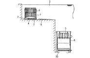
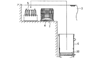
図1は、本発明の第1実施形態によるシュラウドヘッドガイドピン1および吊棒2の取替え時におけるRPV6と気水分離器8との配置状態を示す概略図である。
First Embodiment (FIGS. 1 to 12)
FIG. 1 is a schematic view showing an arrangement state of the
この図1に示すように、本実施形態によるシュラウドヘッドガイドピン1の補修に際しては、原子炉圧力容器(RPV)6がDSプール3内で開蓋状態とされ、RPV6の上部胴の上方が開口する状態となっている。RPV6内には炉心シュラウド30が配置されている。
As shown in FIG. 1, when repairing the shroud
そして、シュラウドヘッド補強用架台7上には、シュラウドヘッド4および気水分離器8が配置され、この配置状態のもとで、シュラウドヘッドガイドピン1の補修を行うようになっている。なお、補強用架台7には、シュラウドヘッド補強用架台7に隣接する配置で仮設パッチ9が搭載されている。
The
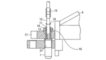
図2は、補修対象となるシュラウドヘッドガイドピン1および吊棒2等の構造部を詳細に示した拡大断面図である。
FIG. 2 is an enlarged cross-sectional view showing in detail the structural parts such as the shroud
図2に示すように、シュラウドヘッド4のガイドピンブラケット17,18にはガイドピンブラケット孔31a,31bがそれぞれ形成されている。そして、ガイドピンブラケット孔31a,31b内に、ガイドピン1がガイドピンブラケット18側からスリーブ11を介して挿入されている。ガイドピン1は、下部側の太径部と上部側の細径部とを有する異径ピン状のものであり、細径部の太径部側にはねじ部12が形成されるとともに、ねじ部12からその先端側は細径のロッド13として形成されている。
As shown in FIG. 2, guide
また、スリーブ11の基端側は外部に臨んで幅拡がりとなる形状とされてガイドピンブラケット17の下端面に係止される一方、スリーブ11の先端側にはネジ部12が形成されており、このねじ部12にはガイドピンブラケット17の上面側からナット16が螺合されている。これにより、ガイドピン1はガイドピンブラケット17に固定される構成となっている。
Further, the base end side of the
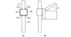
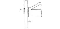
図3(a)は、取替え用吊棒2の構成を一部断面として示す側面図であり、図3(b)は、その吊棒2を設けたシュラウドヘッド4の構成を示している。
FIG. 3A is a side view showing the configuration of the
図3(a),(b)に示すように、取替え用吊棒2は、既設の吊棒ブラケット10と取り合うチャンネル20構造の一面に既設の吊棒2と干渉する部分に切り欠きを設け、その切り欠き部と対面するチャンネル20の面に切断した吊棒と同等の長さを有する新しい吊棒21を溶接部21aにより取付けられている。
As shown in FIGS. 3 (a) and 3 (b), the
この取替え用吊棒20,21は損傷した吊棒2を切断した吊棒ブラケット10に横(半径)方向からスライドさせるように被せられ、機械的に吊棒ブラケット10に取付けられる。
The
次に、図4〜図12を参照して、シュラウドヘッドの補修工程について説明する。 Next, a repair process of the shroud head will be described with reference to FIGS.
上述したように、シュラウドヘッド4を炉心シュラウド30に据付ける時には、シュラウドヘッド4に取付けられているシュラウドヘッドボルトとしてのガイドピン1を備えている。
As described above, when the
また、炉心シュラウド4に取付けられているシュラウドヘッドボルトラグおよびシュラウドヘッドリム胴に設けられている耐震ピン用孔とシュラウド上部リング上面に取付けられている耐震ピンとが干渉しない状態でシュラウドヘッド4の位置決めができるように、シュラウドヘッド4にはそのシュラウドヘッド4に取付けられたガイドピンブラケットと取り合うガイドピン1が設けられている。このガイドピン1の一部もしくは全てを切断撤去するとともに、その撤去した部位に新たなガイドピン1を導入することにより据付けられる。
In addition, the positioning of the
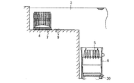
図4に示すように、シュラウドヘッドを補修する場合には、シュラウドヘッドガイドピン1および吊棒2を補修するスペースをDSプール3内に確保するため、DSプール3内に仮置きされている蒸気乾燥器5を一時的に仮設置されているシュラウドヘッド4の頭上を越えてRPV6内に戻す。この場合、蒸気乾燥器5は線量が高くないことから気中移動が可能である。
As shown in FIG. 4, when repairing the shroud head, steam temporarily placed in the
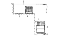
次に、図5に示すように、DSプール3内の蒸気乾燥器5が仮置きされていた場所に仮設置するシュラウドヘッド補修用架台7を設置し、その後、図6に示すように、シュラウドヘッド4をシュラウドヘッド補修用架台7に移動する。
Next, as shown in FIG. 5, a shroud head repairing base 7 to be temporarily installed is installed at the place where the
シュラウドヘッド補修架台7はオペレーションフロアでの被ばく線量を考慮し、シュラウドヘッド4に取付けられている気水分離器8の上端が1m以上水没している高さに制限する。
The shroud head repair stand 7 is limited to a height at which the upper end of the
そして、図7に示すように、シュラウドヘッド4をシュラウドヘッド補修架台7に移動した際、DSプール3の床面からプール水の漏洩がある場合には、その損傷部位に仮設パッチ9を設置し、漏洩を止めDSプール3内の水を抜くことが可能な状態となったときに本格的なDSプール3の補修を行なう。
Then, as shown in FIG. 7, when the
なお、変形した吊棒2は、吊棒ブラケット10の下方をEDM装置により切断撤去する。さらに、吊棒ブラケット10下面の吊棒2残存部がなくなるようにEDM装置により追い込み加工を行ない、吊棒ブラケット10下面と吊棒2残存部が面一になるようにする。
The
変形したガイドピン1については、以下の手順により撤去する。
The
i)EDM装置によりスリーブ11下端位置でガイドピンのねじ部12下端を切断し、ガイドピン1太径部を撤去する。
i) Cut the lower end of the threaded
ii)この状態でロッド13を回転させることが可能か確認する。ロット13が回転しない場合には、スリーブ11およびガイドピンのねじ部12が損傷しているので、損傷している範囲のねじ部12をEDMにより除去する。加工はロッド13が回転できるようになるまで行なう。
ii) Check if it is possible to rotate the
iii)ロッド13のコネクタ15の下方に取付けられているストッパ14を、EDM装置により外周から追い込み加工し、ロッド13から取り外す。
iii) The
iv)ロッド13を回転させスリーブ11とねじで取り合っているガイドピン1を、スリーブ11の下方に引き抜いた状態にする。
iv) The
v)コネクタ15の下方でロッド13をEDM装置により切断し、ガイドピン1をスリーブ11から抜き取り撤去する。
v) The
vi)コネクタ15の上方でロッド13をEDM装置により切断し、コネクタ15を撤去する。
vi) The
vii)ロッド13を上方に引き上げサポートリングから引き抜き撤去する。この状態で、既設のスリーブ11部を残してガイドピン1が取り外された状態となる。
vii) Pull the
viii)取替え用吊棒2は、既設の吊棒ブラケット10と取り合うチャンネル20構造の一面に既設の吊棒2と干渉する部分に切り欠きを設け、その切り欠き部と対面するチャンネル20の面に切断した吊棒と同等の長さを有する新しい吊棒21を溶接により取付けられている構造となっている。
viii) The
この取替え用吊棒20,21は損傷した吊棒2を切断した吊棒ブラケット10に横(半径)方向からスライドさせるように被せ、機械的に吊棒ブラケット10に取付ける。
The
ix)取替え用ガイドピンは既設の可動式のガイドピン1とは異なり固定式とする。この固定式のガイドピン1は既設と同様に、シュラウドヘッド4がシュラウド30に着座する前はシュラウド側のガイドピンブラケット孔31のクリアランスが小さく、シュラウドヘッド4がシュラウド30に着座した場合には、ガイドピン1とシュラウド側のガイドピンブラケット孔31のクリアランスが大きくなるように二段径構造とする。
ix) The replacement guide pin is fixed, unlike the existing
x)取替え用ガイドピン1の段差の軸方向の寸法の取り合いは、既設のガイドピン1が最下端位置に下ろした場合と同じとすることにより上記の取り合いを提供することができる。
x) The above-described connection can be provided by making the axial dimension of the step of the
取替え用ガイドピン1は、既設のスリーブ11に取付けることにより既設と同様のシュラウドヘッドのガイド機能を提供できる。
The
取替え用ガイドピン1の取付けは、既設のスリーブ11下端から取替え用ガイドピン1をスリーブ11に挿入し、ガイドピン取付治具を用いて取替え用ガイドピン1を回転させスリーブ11にねじ込み固定する。スリーブ11の上方から突き出たロッド13部を用いて既設のナット16を利用し回り止めを機械的に行なう。
The
xi)図8に示すように、ガイドピン1および吊棒2の補修中もしくは完了後に、本来のシュラウドヘッド設置位置に本設シュラウドヘッド架台40を水中遠隔で仮設置しておく。なお、プラント起動後にDSプール3内の水を排水し、作業員が近づいてシュラウドヘッド架台40の本取付けを実施する。
xi) As shown in FIG. 8, during or after the repair of the
xii)図9に示すように、ガイドピン1および吊棒2の補修完了後に、本来のシュラウドヘッド設置位置に仮置きした本設シュラウドヘッド架台40にシュラウドヘッド4を移動する。
xii) As shown in FIG. 9, after the repair of the
xiii)図10に示すように、シュラウドヘッド補修用架台7を蒸気乾燥器設置位置から撤去し、シュラウドヘッド補修期間中にRPV6内へ退避していた蒸気乾燥器5を本来のDSプール3内の蒸気乾燥器設置位置へシュラウドヘッド4上を移動し仮置きする。
xiii) As shown in FIG. 10, the shroud head repair stand 7 is removed from the steam dryer installation position, and the
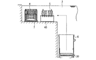
xiv)なお、図11に示すように、シュラウドヘッド4をシュラウドヘッド補修架台7上で補修中にRPV6内へアクセスする作業が発生する場合には、DSプール3内の本来はシュラウドヘッド4の設置位置に蒸気乾燥器仮受け台43を設置する。
xiv) As shown in FIG. 11, when an operation to access the
xv)そして、図12に示すように、RPV6内に退避している蒸気乾燥器5をその仮受け台43上に移動し、炉内での作業が完了した後蒸気乾燥器5をRPV6内に再び退避する。
xv) Then, as shown in FIG. 12, the
以上の実施形態によれば、地震等により変形したシュラウドヘッドのガイドピンおよび吊棒を水中遠隔作業で交換することが可能となる。 According to the above embodiment, it becomes possible to exchange the guide pin and the suspension rod of the shroud head deformed by an earthquake or the like by underwater remote work.
また、変形しシュラウドヘッドのガイド機能を喪失し、かつシュラウドのガイドピンブラケットと干渉する可能性のあるガイドピン、および変形しシュラウドと干渉してしまう吊棒を交換することにより、シュラウドヘッドを再び使用することが可能となる。 The shroud head can be removed again by replacing guide pins that can deform and lose the guide function of the shroud head and can interfere with the guide pin bracket of the shroud, and suspension rods that deform and interfere with the shroud. Can be used.
さらに、本実施形態によれば、遮蔽を考慮した補修用架台を用いることにより、気水分離器の上方に十分な水遮蔽を確保することができ、取替作業中の被ばく量を低く抑えることが可能となる。 Furthermore, according to the present embodiment, by using a repair stand in consideration of shielding, it is possible to ensure sufficient water shielding above the steam separator, and to keep the exposure dose during replacement work low. Is possible.
[第2実施形態](図13)
図13は、本発明の第2実施形態によるシュラウドヘッドガイドピン1の構成を示す拡大断面図である。
Second Embodiment (FIG. 13)
FIG. 13 is an enlarged cross-sectional view showing the configuration of the shroud
本実施形態では、第1実施形態から以下を変更するものである。すなわち、第1実施形態では、既設のガイドピン1を構成する部品のうちスリーブ11を残してガイドピン1を復旧した。これに対し、本実施形態では、既設のスリーブ11も撤去しガイドピン1を復旧するものである。
In the present embodiment, the following changes are made from the first embodiment. That is, in the first embodiment, the
図13において、既設のスリーブ11は、スリーブ11自身の鍔部とナット16によりガイドピンブラケット17を挟み込むように取付けられている。
In FIG. 13, the existing
スリーブ11を取り外すには、ナット16の回り止め溶接を解除し、ナット16を回転させナット16とスリーブ11を分離して取り外す。もしくは、ガイドピンブラケット17を挟み込んでいるスリーブ11の鍔部をEDM装置により削除し、ナット16とスリーブ11を取り外す。
In order to remove the
新ガイドピン1は以下の手順で取付ける。まず、新ガイドピン1をガイドピンブラケット17の下方からガイドピンブラケット17に挿入し、ナット16等により機械的にガイドピンブラケット17に固定する。
The
新ガイドピンの構造は、ナット16等により固定するためにガイドピンブラケット17を挟み込む鍔部を有している。
The structure of the new guide pin has a flange portion that sandwiches the
本実施形態においては、第1実施形態と同様に固定式の二段径構造とするが、シュラウド側のガイドピンブラケット孔31とのクリアランスがシュラウド耐震ピンのクリアランスと同程度になるよう第1の形態よりガイドピン1の径を小さくしている。
In the present embodiment, a fixed two-stage diameter structure is used as in the first embodiment, but the first clearance is such that the clearance from the shroud guide
このような第2実施形態においても、第1実施形態と同様の作用効果が奏される。 In the second embodiment as described above, the same effects as those of the first embodiment are exhibited.
[第3実施形態](図14)
図14は、本発明の第3実施形態によるシュラウドヘッドガイドピン1および吊棒2の構成を示す拡大断面図である。
[Third Embodiment] (FIG. 14)
FIG. 14 is an enlarged cross-sectional view showing configurations of the shroud
本実施形態では、第1実施形態から以下を変更する。すなわち、第1実施形態では、既設のガイドピン1を構成する部品のうちスリーブ11を残して固定式のガイドピン1を復旧した。
In the present embodiment, the following changes are made from the first embodiment. That is, in the first embodiment, the fixed
これに対し、本実施形態では、第1実施形態と同様にスリーブ11を残したままとするが、図14に示すように、既設と同様に可動式のガイドピン1に復旧する。
On the other hand, in this embodiment, the
すなわち、第3実施形態では、第1実施形態と同様の手順によりスリーブ11を除いた既設のガイドピン1を撤去する。その後、以下の手順により新ガイドピン1を取付ける。
That is, in the third embodiment, the existing
新ガイドピン1をスリーブ11に下方から挿入後、新ガイドピン1を回転させ、ストッパ取付け位置がスリーブ11上端より上方なる位置とする。
After the
新ガイドピン1の上方から、ストッパ14を新ガイドピン1に取付け、機械的に固定する。
A
新ガイドピン1を回転させ、最下端ストッパ14がスリーブ111上端に当たる位置まで下げた後、新ガイドピン上端にコネクタ15を取付ける。
After the
ロッド13をシュラウドヘッドのサポートリング(図示せず)に挿入し、ロッド13下端をコネクタ15に接続する。
The
六角ブロックと上部サポートリングのクリアランスが規定値になるまでロッド13をコネクタ15にねじ込んだ後、ロッド13とコネクタ15を固定する。
After the
このような第3実施形態においても、第1実施形態と同様の作用と効果が奏される。ただし、据え付ける部品数が多くなるため第1実施形態に比べ工期が長くなる。 In such a third embodiment, the same operations and effects as the first embodiment are exhibited. However, since the number of components to be installed increases, the construction period becomes longer than that in the first embodiment.
[第4実施形態](図15)
図15は、本発明の第4施形態によるシュラウドヘッドガイドピン1および吊棒2の構成を示す拡大断面図である。
[Fourth Embodiment] (FIG. 15)
FIG. 15 is an enlarged cross-sectional view showing configurations of the shroud
本実施形態では、第1実施形態から以下の工程を変更する。第1実施形態では、既設のガイドピン1を構成する部品のうち、スリーブ11を残して固定式のガイドピン1を復旧した。
In the present embodiment, the following steps are changed from the first embodiment. In the first embodiment, among the parts constituting the existing
これに対し、本実施形態では、図14に示すように、既設のスリーブ11も撤去し、可動式のガイドピン1を復旧する。
On the other hand, in this embodiment, as shown in FIG. 14, the existing
本実施形態では、第3実施形態と同様の手順により、既設のガイドピン1を全て撤去する。その後、新スリーブ11をガイドピンブラケット17の下方から挿入し、新スリーブ11と新ナット16でガイドピンラケット17を挟み込み固定する。
In the present embodiment, all the existing
その後は、第3の形態と同様の手順で新ガイドピン1を取付ける。
Thereafter, the
新ガイドピン1は、第2の形態と同様に、シュラウド側のガイドピンブラケット孔31とのクリアランスがシュラウド耐震ピンのクリアランスと同程度になるように、第1の形態よりもガイドピン1の径を小さくしている。
As with the second embodiment, the
本実施形態においても、第1実施形態と同様の作用と効果が奏される。ただし、据え付ける部品数が多くなるため第1実施形態に比べ工期が長くなる。 Also in this embodiment, the same operation and effect as the first embodiment are exhibited. However, since the number of components to be installed increases, the construction period becomes longer than that in the first embodiment.
[第5実施形態](図16)
図16は、本発明の第5施形態によるシュラウドヘッドガイドピン1および吊棒2の構成を示す拡大断面図である。
[Fifth Embodiment] (FIG. 16)
FIG. 16 is an enlarged cross-sectional view showing configurations of the shroud
本実施形態では、第1実施形態から以下を変更するものである。すなわち、第1実施形態では、既設の吊棒の吊棒ブラケット10から下方を切断し、切断した部位に新吊棒21を復旧した。
In the present embodiment, the following changes are made from the first embodiment. That is, in 1st Embodiment, the downward direction was cut | disconnected from the
これに対し、本実施形態では、既設の吊棒の吊棒ブラケット10から下方を切断し、シュラウドヘッド架台40をDSプール内に設置することを前提とし、新しい吊棒21は復旧しない構成とする。
On the other hand, in this embodiment, it is assumed that the lower part is cut from the
この構成により、本実施形態においても、第1実施形態と同様の作用と効果が奏される。 With this configuration, the same operations and effects as in the first embodiment are also achieved in this embodiment.
[第6実施形態](図17)
図17は、本発明の第6施形態によるシュラウドヘッドガイドピン1および吊棒2の構成を示す拡大断面図である。
[Sixth Embodiment] (FIG. 17)
FIG. 17 is an enlarged cross-sectional view showing configurations of the shroud
本実施形態では、第1実施形態から以下を変更するものである。すなわち、第1実施形態では、既設の吊棒の吊棒ブラケット10から下方を切断し、切断した部位に新吊棒を復旧した。
In the present embodiment, the following changes are made from the first embodiment. That is, in 1st Embodiment, the downward direction was cut | disconnected from the hanging
これに対し、本実施形態では、第1実施形態と同様に、切断した部位に新吊棒を取付けるものであるが、吊棒ブラケット10内に残存している既設の吊棒材に下面側からEDM装置により軸方向に雌ねじを加工する。なお、新吊棒21は、この雌ねじと取り合う雄ねじ部を有している。
On the other hand, in the present embodiment, as in the first embodiment, a new suspension rod is attached to the cut portion, but the existing suspension rod remaining in the
この構成により、本実施形態においても、第1実施形態と同様の作用と効果が奏される。 With this configuration, the same operations and effects as in the first embodiment are also achieved in this embodiment.
[第7実施形態](図18)
図18は、本発明の第7施形態によるシュラウドヘッドガイドピン1および吊棒2の構成を示す拡大断面図である。
[Seventh Embodiment] (FIG. 18)
FIG. 18 is an enlarged cross-sectional view showing configurations of the shroud
本実施形態では、第1実施形態から以下を変更するものである。すなわち、第1実施形態では、既設の吊棒の吊棒ブラケット10から下方を切断し、切断した部位に新吊棒21を復旧した。
In the present embodiment, the following changes are made from the first embodiment. That is, in 1st Embodiment, the downward direction was cut | disconnected from the
これに対し、本実施形態では、吊棒ブラケット10上下面で吊棒を切断し撤去する。吊棒ブラケット10内に残存している既設の吊棒には既設の吊棒直径よりも小径な通し孔をEDM装置により加工する。
On the other hand, in this embodiment, the suspension bar is cut and removed at the upper and lower surfaces of the
新吊棒21は吊棒ブラケット10から上方部分と下方部分の二分割構造とし、上部側の新吊棒21はその上端に既設と同様の吊耳を設けている。また、上部側の新吊棒21の下端部は吊棒ブラケット10に加工した穴に通るように細径となっており、最下端部は雄ねじ構造となっている。
The
下部側の新吊棒21は、上部側の新吊棒の雄ねじ部と取り合う雌ねじ部が設けてある。
The lower
上部側の新吊棒と下部側の新吊棒21のねじ部で吊棒ブラケット10を挟み込み新吊棒21を吊棒ブラケット10に固定する。
The
以上の構成により、第7実施形態においても、第1実施形態と同様の作用と効果が奏される。ただし、据え付ける部品数が多くなるため第1実施形態に比べて工期が長くなる。 With the above configuration, the same operations and effects as in the first embodiment are also achieved in the seventh embodiment. However, since the number of components to be installed is increased, the construction period is longer than that in the first embodiment.
[第8実施形態](図19)
図19は、本発明の第8施形態によるシュラウドヘッドガイドピン1および吊棒2の構成を示す拡大断面図である。
[Eighth Embodiment] (FIG. 19)
FIG. 19 is an enlarged cross-sectional view showing configurations of the shroud
本実施形態では、第1実施形態から以下の工程を変更するものである。すなわち、第1実施形態では、既設の吊棒2の吊棒ブラケット10から下方を切断し、切断した部位に新吊棒21を復旧した。
In the present embodiment, the following steps are changed from the first embodiment. That is, in 1st Embodiment, the downward direction was cut | disconnected from the
これに対し、第8実施形態では、吊棒ブラケット10上下面で吊棒2を切断し撤去する。さらに、吊棒ブラケット10内に残存している既設吊棒2を吊棒2の溶着部をEDM装置で除去することにより、既設吊棒2を完全に除去する。
On the other hand, in the eighth embodiment, the
新吊棒21は既設の吊棒2と同様に一体型で上端に既設と同様の吊耳を設けている。
The
新吊棒21の取付けは、既設の吊棒2と同様に吊棒ブラケット10の上下面に溶接で取付ける。
The
第8実施形態においても、第1実施形態と同様の作用と効果が奏される。 In the eighth embodiment, the same operations and effects as in the first embodiment are achieved.
ただし、据え付ける部品数が多くなるため第1実施形態に比べ工期が長くなる。 However, since the number of components to be installed increases, the construction period becomes longer than that in the first embodiment.
[第9実施形態]
本実施形態では、第1〜4実施形態の新ガイドピン1と第1,5〜8実施形態の新吊棒21を組み合わせる。
[Ninth Embodiment]
In the present embodiment, the
以上の構成により、本実施形態においても、第1実施形態と同様の作用と効果が奏される。 With the above configuration, the same operation and effect as in the first embodiment can be achieved in the present embodiment.
[他の実施形態]
本発明においては、シュラウドヘッドをシュラウドに据付時、シュラウドヘッドに取付けられているシュラウドヘッドボルトとシュラウドに取付けられているシュラウドヘッドボルトラグおよび一部のプラントではシュラウドヘッドリム胴に設けられている耐震ピン用孔とシュラウド上部リング上面に取付けられている耐震ピンが干渉しないように、シュラウドヘッドの位置決めができるようシュラウドヘッドにはシュラウドに取付けられたガイドピンブラケットと取り合うガイドピンが設けられるものとすることができる。
[Other Embodiments]
In the present invention, when the shroud head is installed on the shroud, the shroud head bolt attached to the shroud head, the shroud head bolt lug attached to the shroud, and in some plants, the seismic resistance provided on the shroud head rim body. The shroud head shall be provided with a guide pin that mates with a guide pin bracket attached to the shroud so that the shroud head can be positioned so that the pin hole and the seismic pin mounted on the upper surface of the shroud upper ring do not interfere with each other. be able to.
そして、このガイドピンの一部もしくは全てを切断撤去するとともに、その撤去した部位に新たなガイドピンを導入して据付けるシュラウドヘッドの補修方法とすることができる。 And it can be set as the repair method of the shroud head which introduce | transduces and installs a new guide pin in the removed site | part while cutting and removing a part or all of this guide pin.
また、シュラウドヘッドをDSプール仮置き時に使用する吊棒の一部もしくは全てを切断撤去するとともに、その撤去した部位に新たな吊棒を導入して据付けるシュラウドヘッドの補修方法とすることができる。 Further, it is possible to provide a method for repairing the shroud head in which the shroud head is partially removed or removed from the DS pool temporarily placed, and a new suspension bar is introduced and installed in the removed part. .
また、本発明においては、シュラウドヘッドガイドピンおよび吊り棒を補修するスペースを確保するため、DSプール内に仮置きされている蒸気乾燥器を一時的にRPV内に戻すシュラウドヘッドの補修方法とすることができる。 Moreover, in this invention, in order to ensure the space which repairs a shroud head guide pin and a suspension rod, it is set as the repair method of the shroud head which temporarily returns the steam dryer temporarily placed in DS pool in RPV. be able to.
また、本発明においては、シュラウドヘッドの補修方法において、蒸気乾燥器は仮設置されているシュラウドヘッドの頭上を越えて、PRV内に戻すシュラウドヘッドの補修方法とすることができる。 In the present invention, the shroud head repair method may be a shroud head repair method in which the steam dryer is returned over the head of the temporarily installed shroud head and returned to the PRV.
また、本発明においては、DSプール内の蒸気乾燥器が仮置きされていた場所に仮設置するシュラウドヘッド補修用架台を設置し、シュラウドヘッドをシュラウドヘッド補修用架台に移動するシュラウドヘッド補修方法とすることができる。 Further, in the present invention, a shroud head repair method in which a shroud head repair base temporarily installed at a place where the steam dryer in the DS pool was temporarily placed is installed, and the shroud head is moved to the shroud head repair base; can do.
また、本発明においては、シュラウドヘッド補修架台はオペレーションフロアでの被ばく線量を考慮しシュラウドヘッドに取付けられている気水分離器の上端が1m以上水没している高さに制限するシュラウドヘッド補修方法とすることができる。 Further, in the present invention, the shroud head repair stand is limited to a height at which the upper end of the air / water separator attached to the shroud head is submerged by 1 m or more in consideration of the exposure dose on the operation floor. It can be.
また、本発明においては、DSプール内で損傷したシュラウドヘッドガイドピンおよび吊り棒を水中で遠隔切断装置により切断し、撤去するシュラウドヘッドの補修方法とすることができる。 Moreover, in this invention, it can be set as the repair method of the shroud head which cut | disconnects and removes the shroud head guide pin and suspension rod which were damaged in DS pool in water with a remote cutting device.
また、本発明においては、シュラウドヘッドをシュラウドヘッド補修架台に移動した際、DSプールの床面からプール水の漏洩がある場合には、その損傷部位に仮設パッチを設置するシュラウドヘッドの補修方法とすることができる。 Further, in the present invention, when there is a leakage of pool water from the floor surface of the DS pool when the shroud head is moved to the shroud head repair stand, a shroud head repair method for installing a temporary patch at the damaged site; can do.
また、本発明においては、新たなガイドピンを水中遠隔で損傷したガイドピンを切断、撤去した部位へ水中遠隔で取付けるシュラウドヘッドの補修方法とすることができる。 Moreover, in this invention, it can be set as the repair method of the shroud head which attaches a new guide pin to the site | part which cut | disconnected and removed the guide pin which was damaged remotely underwater.
また、本発明においては、新たな吊り棒を水中遠隔で損傷した吊り棒を切断、撤去した部位へ水中遠隔で取付けるシュラウドヘッドの補修方法とすることができる。 Moreover, in this invention, it can be set as the repair method of the shroud head which attaches a new suspension rod to the site | part which cut | disconnected and removed the suspension rod damaged remotely underwater.
また、本発明においては、ガイドピンおよび吊棒の補修中もしくは完了後に、本来のシュラウドヘッド設置位置に本設シュラウドヘッド架台を水中遠隔で仮設置し、プラント起動後にDSプール内の水を排水し、作業員が近づいてシュラウドヘッド架台の本取付けを実施するシュラウドヘッドの補修方法とすることができる。 In addition, in the present invention, the permanent shroud head mount is temporarily installed underwater at the original shroud head installation position during or after the repair of the guide pin and the suspension rod, and the water in the DS pool is drained after the plant is started. Thus, the shroud head repair method can be used in which the worker approaches and performs the main mounting of the shroud head frame.
また、本発明においては、ガイドピンおよび吊棒の補修完了後に、本来のシュラウドヘッド設置位置に仮置きした本設シュラウドヘッド架台に、シュラウドヘッドを移動するシュラウドヘッドの補修方法とすることができる。 Moreover, in this invention, it can be set as the repair method of the shroud head which moves a shroud head to the permanent shroud head mount temporarily set | placed in the original shroud head installation position after completion of repair of a guide pin and a suspension rod.
また、本発明においては、シュラウドヘッド補修用架台を蒸気乾燥器設置位置から撤去し、シュラウドヘッド補修期間中にRPV内へ退避していた蒸気乾燥器を本来のDSプール内の蒸気乾燥器設置位置へシュラウドヘッド上を移動し、仮置きするシュラウドヘッドの補修方法とすることができる。 In the present invention, the shroud head repair stand is removed from the steam dryer installation position, and the steam dryer that has been evacuated into the RPV during the shroud head repair period is installed in the original DS pool steam dryer installation position. A method of repairing the shroud head that moves on the shroud head and temporarily places it can be used.
また、本発明においては、シュラウドヘッドをシュラウドヘッド補修架台上で補修中にRPV内へアクセスする作業が発生する場合には、DSプール内の本来はシュラウドヘッドの設置位置に蒸気乾燥器仮受け台を設置し、RPV内に退避している蒸気乾燥器をその仮受け台上に移動し、炉内での作業が完了した後蒸気乾燥器をRPV内に再び退避するシュラウドヘッドの補修方法とすることができる。 Further, in the present invention, when an operation for accessing the shroud head into the RPV occurs while repairing the shroud head on the shroud head repair stand, the steam dryer provisional cradle is originally placed at the shroud head installation position in the DS pool. A method of repairing the shroud head in which the steam dryer retracted in the RPV is moved onto the temporary cradle and the steam dryer is retracted again in the RPV after the operation in the furnace is completed. be able to.
また、本発明においては、既設ガイドピンの部品の一部であるスリーブを取り外さずに既設と同様な構造の新しいガイドピンを取付けるシュラウドヘッドの補修方法とすることができる。 Moreover, in this invention, it can be set as the repair method of the shroud head which attaches the new guide pin of the structure similar to the existing, without removing the sleeve which is a part of components of the existing guide pin.
また、本発明においては、既設ガイドピンを全て取り外し、シュラウドに取付けられているガイドピンブラケットのガイドピン用孔とのクリアランスが、シュラウドに取付けられている耐震ピントシュラウドヘッドリム胴の耐震ピン用孔とのクリアランスと同度となるような径を有するガイドピンを取付けるシュラウドヘッドの補修方法とすることができる。 Further, in the present invention, all the existing guide pins are removed, and the clearance with the guide pin hole of the guide pin bracket attached to the shroud is the earthquake resistant pin hole of the earthquake resistant pin shroud head rim body attached to the shroud. And a shroud head repair method for attaching a guide pin having a diameter that is the same as the clearance.
また、本発明においては、既設吊棒の部品の一部である吊棒ブラケットから下方部を取り外し、新しい吊棒下方部を機械的に取付けるシュラウドヘッドの補修方法とすることができる。 Moreover, in this invention, it can be set as the repair method of the shroud head which removes a lower part from the suspension bar bracket which is a part of components of the existing suspension bar, and attaches a new suspension bar lower part mechanically.
また、本発明においては、既設吊棒を全て取り外し、新しい吊棒を機械的もしくは溶接構造で取付けるシュラウドヘッドの補修方法とすることができる。 Moreover, in this invention, it can be set as the repair method of the shroud head which removes all the existing suspension bars and attaches a new suspension bar mechanically or with a welding structure.
また、本発明においては、シュラウドヘッド架台を設置することを前提に既設吊棒の部品の一部である吊棒ブラケットから下方部を取り外すシュラウドヘッドの補修方法とすることができる。 Moreover, in this invention, it can be set as the repair method of the shroud head which removes a downward part from the suspension rod bracket which is a part of components of the existing suspension rod on the assumption that a shroud head mount is installed.
1 ガイドピン
2 吊棒
3 DSプール
4 シュラウドヘッド
5 蒸気乾燥器
6 RPV
7 シュラウドヘッド補修架台
8 気水分離器
9 仮設パッチ
10 吊棒ブラケット
11 スリーブ
12 ねじ部
13 ロッド
14 ストッパ
15 コネクタ
16 ナット
17、18 ガイドピンブラケット
20 チャンネル
21 新吊棒
21a 溶接部
30 炉心シュラウド
31a,31b ガイドピンブラケット孔
40 シュラウドヘッド架台
43 蒸気乾燥器仮受け台
1
7 Shroud
Claims (8)
Priority Applications (1)
| Application Number | Priority Date | Filing Date | Title |
|---|---|---|---|
| JP2008209231A JP5106314B2 (en) | 2008-08-15 | 2008-08-15 | How to repair the shroud head |
Applications Claiming Priority (1)
| Application Number | Priority Date | Filing Date | Title |
|---|---|---|---|
| JP2008209231A JP5106314B2 (en) | 2008-08-15 | 2008-08-15 | How to repair the shroud head |
Publications (2)
| Publication Number | Publication Date |
|---|---|
| JP2010043995A true JP2010043995A (en) | 2010-02-25 |
| JP5106314B2 JP5106314B2 (en) | 2012-12-26 |
Family
ID=42015488
Family Applications (1)
| Application Number | Title | Priority Date | Filing Date |
|---|---|---|---|
| JP2008209231A Active JP5106314B2 (en) | 2008-08-15 | 2008-08-15 | How to repair the shroud head |
Country Status (1)
| Country | Link |
|---|---|
| JP (1) | JP5106314B2 (en) |
Citations (14)
| Publication number | Priority date | Publication date | Assignee | Title |
|---|---|---|---|---|
| JPS61296293A (en) * | 1985-06-26 | 1986-12-27 | 株式会社日立製作所 | Shroud head clamping mechanism |
| JPS63133093A (en) * | 1986-11-25 | 1988-06-04 | 株式会社日立製作所 | Nuclear reactor |
| JPH0531591A (en) * | 1991-07-30 | 1993-02-09 | Toshiba Corp | Underwater laser beam welding equipment |
| JPH0580187A (en) * | 1991-09-20 | 1993-04-02 | Hitachi Ltd | Intra-reactor structure maintaining method |
| JPH0633923A (en) * | 1992-07-14 | 1994-02-08 | Hitachi Ltd | Positioning pin |
| JPH08122485A (en) * | 1994-10-27 | 1996-05-17 | Toshiba Corp | Repairing method of shroud in nuclear reactor pressurized container |
| JPH08174377A (en) * | 1994-12-27 | 1996-07-09 | Hitachi Ltd | Remote machining device |
| JPH09304578A (en) * | 1996-05-16 | 1997-11-28 | Hitachi Ltd | Method for handling structure in nuclear reactor and storage device for the structure |
| JP2000304890A (en) * | 1999-04-19 | 2000-11-02 | Hitachi Ltd | Reactor internal structure replacing method |
| JP2001242282A (en) * | 2000-02-25 | 2001-09-07 | Hitachi Ltd | Shroud replacing method |
| JP2002257987A (en) * | 2001-02-27 | 2002-09-11 | Hitachi Ltd | Method of removing in-furnace structures |
| JP2005114434A (en) * | 2003-10-03 | 2005-04-28 | Toshiba Corp | Jig for correcting shroud head |
| JP2007232433A (en) * | 2006-02-28 | 2007-09-13 | Hitachi Ltd | Chimney of natural circulation type boiling water reactor |
| JP2008032468A (en) * | 2006-07-27 | 2008-02-14 | Hitachi Ltd | Neutron instrumentation tube and method for connecting it |
-
2008
- 2008-08-15 JP JP2008209231A patent/JP5106314B2/en active Active
Patent Citations (14)
| Publication number | Priority date | Publication date | Assignee | Title |
|---|---|---|---|---|
| JPS61296293A (en) * | 1985-06-26 | 1986-12-27 | 株式会社日立製作所 | Shroud head clamping mechanism |
| JPS63133093A (en) * | 1986-11-25 | 1988-06-04 | 株式会社日立製作所 | Nuclear reactor |
| JPH0531591A (en) * | 1991-07-30 | 1993-02-09 | Toshiba Corp | Underwater laser beam welding equipment |
| JPH0580187A (en) * | 1991-09-20 | 1993-04-02 | Hitachi Ltd | Intra-reactor structure maintaining method |
| JPH0633923A (en) * | 1992-07-14 | 1994-02-08 | Hitachi Ltd | Positioning pin |
| JPH08122485A (en) * | 1994-10-27 | 1996-05-17 | Toshiba Corp | Repairing method of shroud in nuclear reactor pressurized container |
| JPH08174377A (en) * | 1994-12-27 | 1996-07-09 | Hitachi Ltd | Remote machining device |
| JPH09304578A (en) * | 1996-05-16 | 1997-11-28 | Hitachi Ltd | Method for handling structure in nuclear reactor and storage device for the structure |
| JP2000304890A (en) * | 1999-04-19 | 2000-11-02 | Hitachi Ltd | Reactor internal structure replacing method |
| JP2001242282A (en) * | 2000-02-25 | 2001-09-07 | Hitachi Ltd | Shroud replacing method |
| JP2002257987A (en) * | 2001-02-27 | 2002-09-11 | Hitachi Ltd | Method of removing in-furnace structures |
| JP2005114434A (en) * | 2003-10-03 | 2005-04-28 | Toshiba Corp | Jig for correcting shroud head |
| JP2007232433A (en) * | 2006-02-28 | 2007-09-13 | Hitachi Ltd | Chimney of natural circulation type boiling water reactor |
| JP2008032468A (en) * | 2006-07-27 | 2008-02-14 | Hitachi Ltd | Neutron instrumentation tube and method for connecting it |
Also Published As
| Publication number | Publication date |
|---|---|
| JP5106314B2 (en) | 2012-12-26 |
Similar Documents
| Publication | Publication Date | Title |
|---|---|---|
| JP5411412B2 (en) | How to create a dry environment for underwater repair of reactor bottom heads using segmented caisson | |
| JP4883953B2 (en) | Core spray T-box mounting assembly | |
| CN105023623A (en) | Nuclear fuel assembly repair device and method | |
| JP5761909B2 (en) | Reactor vessel repair method | |
| JPS61231485A (en) | Reusable tube in fuel aggregate | |
| JP5106314B2 (en) | How to repair the shroud head | |
| EP2704152B1 (en) | Nozzle repairing method | |
| JP6029466B2 (en) | Abutment repair method and reactor vessel | |
| KR100873953B1 (en) | Device for pulling welded plug installed in the damaged heat exchanger tubes in steam generator | |
| JP4393011B2 (en) | Replacement method of core spray system equipment | |
| JP6266441B2 (en) | Method for repairing differential pressure detection / borate water injection system piping and nuclear reactor equipped with differential pressure detection / borate water injection system piping repaired by this repair method | |
| JP2005172806A (en) | Tool and method for exchanging fuel assembly nozzle | |
| JP3425217B2 (en) | Sealing device for repairing pressure vessel penetration housing | |
| JP5100703B2 (en) | Shroud head repair method and repair structure | |
| JP2000162376A (en) | Replacing method for reactor internal structure | |
| EP2703704A2 (en) | Nozzle repairing method and nuclear reactor vessel | |
| JP3961150B2 (en) | In-core instrumentation guide tube sealing device | |
| JP5702997B2 (en) | Core support plate installation apparatus and core support plate installation method | |
| JP5159698B2 (en) | Shroud head temporary placement device and method of installing the same | |
| JP2014066629A (en) | Replacement method of reactor core differential pressure and standby liquid control device | |
| JPH02118499A (en) | Repairing method for neutron flux monitor housing | |
| JP2002365390A (en) | Boiling water reactor | |
| JPH10260290A (en) | Method and apparatus for replacing structure in reactor pressure vessel | |
| JP2002196092A (en) | Method of replacing bottom part of pressure vessel in boiling water reactor | |
| JPH06323106A (en) | Pressure test method for main steam lead pipe of turbine |
Legal Events
| Date | Code | Title | Description |
|---|---|---|---|
| RD04 | Notification of resignation of power of attorney |
Free format text: JAPANESE INTERMEDIATE CODE: A7424 Effective date: 20100424 |
|
| A621 | Written request for application examination |
Free format text: JAPANESE INTERMEDIATE CODE: A621 Effective date: 20101214 |
|
| A977 | Report on retrieval |
Free format text: JAPANESE INTERMEDIATE CODE: A971007 Effective date: 20110707 |
|
| A131 | Notification of reasons for refusal |
Free format text: JAPANESE INTERMEDIATE CODE: A131 Effective date: 20110823 |
|
| A521 | Written amendment |
Free format text: JAPANESE INTERMEDIATE CODE: A523 Effective date: 20111024 |
|
| RD01 | Notification of change of attorney |
Free format text: JAPANESE INTERMEDIATE CODE: A7421 Effective date: 20111217 |
|
| TRDD | Decision of grant or rejection written | ||
| A01 | Written decision to grant a patent or to grant a registration (utility model) |
Free format text: JAPANESE INTERMEDIATE CODE: A01 Effective date: 20120904 |
|
| A01 | Written decision to grant a patent or to grant a registration (utility model) |
Free format text: JAPANESE INTERMEDIATE CODE: A01 |
|
| A61 | First payment of annual fees (during grant procedure) |
Free format text: JAPANESE INTERMEDIATE CODE: A61 Effective date: 20121002 |
|
| R151 | Written notification of patent or utility model registration |
Ref document number: 5106314 Country of ref document: JP Free format text: JAPANESE INTERMEDIATE CODE: R151 |
|
| FPAY | Renewal fee payment (event date is renewal date of database) |
Free format text: PAYMENT UNTIL: 20151012 Year of fee payment: 3 |