JP2010042163A - Game machine - Google Patents
Game machine Download PDFInfo
- Publication number
- JP2010042163A JP2010042163A JP2008209011A JP2008209011A JP2010042163A JP 2010042163 A JP2010042163 A JP 2010042163A JP 2008209011 A JP2008209011 A JP 2008209011A JP 2008209011 A JP2008209011 A JP 2008209011A JP 2010042163 A JP2010042163 A JP 2010042163A
- Authority
- JP
- Japan
- Prior art keywords
- state
- effect
- game
- display
- value
- Prior art date
- Legal status (The legal status is an assumption and is not a legal conclusion. Google has not performed a legal analysis and makes no representation as to the accuracy of the status listed.)
- Granted
Links
Images


Abstract
Description
本発明は、第1始動領域を遊技媒体が通過したことにもとづいて第1識別情報の可変表示を開始し表示結果を導出表示する第1可変表示手段と、第2始動領域を遊技媒体が通過したことにもとづいて第2識別情報の可変表示を開始し表示結果を導出表示する第2可変表示手段と、遊技者にとって有利な第1状態と遊技者にとって不利な第2状態とに変化する特別可変入賞装置とを有し、第1可変表示手段と第2可変表示手段とのいずれかに特定表示結果が導出表示されたときに遊技者にとって有利な特定遊技状態に移行させるとともに、所定条件が成立したときに通常状態であるときに比べて遊技者にとって有利な特別遊技状態に移行させる遊技機に関する。 The present invention includes a first variable display means for starting variable display of the first identification information based on the fact that the game medium has passed through the first start area and deriving and displaying the display result, and the game medium passing through the second start area. Based on the above, the second variable display means for starting the variable display of the second identification information and deriving and displaying the display result, and the special state which changes between the first state advantageous to the player and the second state disadvantageous to the player A variable winning device, and when a specific display result is derived and displayed on one of the first variable display means and the second variable display means, the player shifts to a specific gaming state advantageous to the player, and a predetermined condition is The present invention relates to a gaming machine that shifts to a special gaming state that is more advantageous to a player than when it is in a normal state when established.
遊技機として、遊技媒体である遊技球を発射装置によって遊技領域に発射し、遊技領域に設けられている入賞口などの入賞領域に遊技球が入賞すると、所定個の賞球が遊技者に払い出されるものがある。さらに、識別情報を可変表示(「変動」ともいう。)可能な可変表示部が設けられ、可変表示部において識別情報の可変表示の表示結果が特定表示結果となった場合に、所定の遊技価値を遊技者に与えるように構成されたものがある。 As a gaming machine, a game ball, which is a game medium, is launched into a game area by a launching device, and when a game ball wins a prize area such as a prize opening provided in the game area, a predetermined number of prize balls are paid out to the player. There is something to be done. Further, a variable display unit capable of variably displaying the identification information (also referred to as “fluctuation”) is provided, and a predetermined game value is obtained when the display result of the variable display of the identification information in the variable display unit becomes a specific display result. Are configured to give the player.
なお、遊技価値とは、遊技機の遊技領域に設けられた可変入賞球装置の状態が打球が入賞しやすい遊技者にとって有利な状態になることや、遊技者にとって有利な状態になるための権利を発生させたりすることや、賞球払出の条件が成立しやすくなる状態になることである。 The game value is the right that the state of the variable winning ball apparatus provided in the gaming area of the gaming machine becomes advantageous for a player who is easy to win, and the right for becoming advantageous for a player. In other words, or a condition for winning a prize ball is easily established.
パチンコ遊技機では、始動入賞口に遊技球が入賞したことにもとづいて可変表示部において開始される特別図柄(識別情報)の可変表示の表示結果として、あらかじめ定められた特定の表示態様が導出表示された場合に、「大当り」が発生する。なお、導出表示とは、図柄を停止表示させることである(いわゆる再変動の前の停止を除く。)。大当りが発生すると、例えば、大入賞口が所定回数開放して打球が入賞しやすい大当り遊技状態に移行する。そして、各開放期間において、所定個(例えば10個)の大入賞口への入賞があると大入賞口は閉成する。そして、大入賞口の開放回数は、所定回数(例えば15ラウンド)に固定されている。なお、各開放について開放時間(例えば29秒)が決められ、入賞数が所定個に達しなくても開放時間が経過すると大入賞口は閉成する。以下、各々の大入賞口の開放期間をラウンドということがある。 In a pachinko machine, a specific display mode determined in advance is derived and displayed as a display result of variable display of a special symbol (identification information) that is started in the variable display unit based on the winning of a game ball at the start winning opening. If this happens, a “big hit” will occur. Note that the derivation display is to stop and display a symbol (excluding stop before so-called re-variation). When a big hit occurs, for example, the big winning opening is opened a predetermined number of times, and the game shifts to a big hit gaming state in which a hit ball is easy to win. And in each open period, if there is a prize for a predetermined number (for example, 10) of the big prize opening, the big prize opening is closed. And the number of times the special winning opening is opened is fixed to a predetermined number (for example, 15 rounds). An opening time (for example, 29 seconds) is determined for each opening, and even if the number of winnings does not reach a predetermined number, the big winning opening is closed when the opening time elapses. Hereinafter, the opening period of each special winning opening may be referred to as a round.
また、可変表示部において、最終停止図柄(例えば左右中図柄のうち中図柄)となる図柄以外の図柄が、所定時間継続して、特定の表示結果と一致している状態で停止、揺動、拡大縮小もしくは変形している状態、または、複数の図柄が同一図柄で同期して変動したり、表示図柄の位置が入れ替わっていたりして、最終結果が表示される前で大当り発生の可能性が継続している状態(以下、これらの状態をリーチ状態という。)において行われる演出をリーチ演出という。また、リーチ状態やその様子をリーチ態様という。さらに、リーチ演出を含む可変表示をリーチ可変表示という。そして、可変表示装置に変動表示される図柄の表示結果が特定の表示結果でない場合には「はずれ」となり、変動表示状態は終了する。遊技者は、大当りをいかにして発生させるかを楽しみつつ遊技を行う。 In the variable display section, the symbols other than the symbol that becomes the final stop symbol (for example, the middle symbol of the left and right middle symbols) continue for a predetermined time, stop, swing, There is a possibility that a big hit will occur before the final result is displayed due to the state of scaling or deformation, or multiple symbols changing synchronously with the same symbol, or the position of the display symbol being switched An effect performed in a continuing state (hereinafter, these states are referred to as reach states) is referred to as reach effect. Further, the reach state and its state are referred to as a reach mode. Furthermore, variable display including reach production is called reach variable display. Then, when the display result of the symbol variably displayed on the variable display device is not a specific display result, it becomes “out of” and the variability display state ends. A player plays a game while enjoying how to generate a big hit.
このような遊技機において、それぞれ異なる始動入賞口への遊技球の入賞にもとづいて特別図柄を可変表示する2つの可変表示器を備えた遊技機がある(例えば、特許文献1参照。)。特許文献1には、それぞれの始動入賞口への遊技球の入賞にもとづいて確変大当り(通常状態に比べて「大当り」が発生やすい状態に制御する大当り)に選択される割合が異なることが記載されている。
Among such gaming machines, there is a gaming machine provided with two variable indicators that variably display special symbols based on winning of game balls at different start winning holes (see, for example, Patent Document 1).
特許文献1に記載された遊技機では、設計変更をするときに全ての変動パターンのデータの振分けを変更しなければならず、設計変更が煩雑になっていた。
In the gaming machine described in
そこで、本発明は、容易に設計変更することができる遊技機を提供することを目的とする。 Therefore, an object of the present invention is to provide a gaming machine that can be easily changed in design.
本発明による遊技機は、第1始動領域(例えば、第1始動入賞口13)を遊技媒体(例えば、遊技球)が通過したことにもとづいて第1識別情報(例えば、第1特別図柄)の可変表示を開始し表示結果を導出表示する第1可変表示手段(例えば、第1特別図柄表示器8a)と、第2始動領域(例えば、第2始動入賞口14)を遊技媒体(例えば、遊技球)が通過したことにもとづいて第2識別情報(例えば、第2特別図柄)の可変表示を開始し表示結果を導出表示する第2可変表示手段(例えば、第2特別図柄表示器8b)と、遊技者にとって有利な第1状態(例えば、大入賞口が開放された状態(開状態))と遊技者にとって不利な第2状態(例えば、大入賞口が閉鎖された状態(閉状態))とに変化する特別可変入賞装置(例えば、特別可変入賞球装置20)とを有し、第1可変表示手段と第2可変表示手段とのいずれかに特定表示結果(例えば、大当り図柄)が導出表示されたときに遊技者にとって有利な特定遊技状態(例えば、大当り遊技状態)に移行させるとともに、所定条件が成立したとき(例えば、15R確変大当りまたは突然確変大当りと決定したとき)に通常状態であるときに比べて遊技者にとって有利な特別遊技状態(例えば、確変状態)に移行させる遊技機であって、特定遊技状態には特別可変入賞装置を第1期間(例えば、15ラウンド)第1状態に変化させる第1特定遊技状態(例えば、15R(ラウンド)通常大当りや15R確変大当りにもとづく大当り遊技状態)と、特別可変入賞装置を第1期間よりも短い第2期間(例えば、2ラウンド)第1状態に変化させる第2特定遊技状態(例えば、突然確変大当りにもとづく大当り遊技状態)とがあり、第1可変表示手段における第1識別情報の可変表示または第2可変表示手段における第2識別情報の可変表示に対応した演出識別情報の可変表示が実行される演出表示部(例えば、演出表示装置9)と、第1始動領域を遊技媒体が通過したこと、または第2始動領域を遊技媒体が通過したことにもとづいて、特定遊技状態に移行させるか否かと、特定遊技状態に移行させるときに第1特定遊技状態と第2特定遊技状態とのいずれに移行させるかと、特別遊技状態に移行させるか否かと、特定遊技状態とは異なる特殊遊技状態(例えば、小当り遊技状態)に移行させるか否かとを表示結果の導出表示以前に決定する事前決定手段(例えば、遊技制御用マイクロコンピュータ560におけるステップS61,S62,S72,S73の処理を実行する部分)と、事前決定手段によって特定表示結果としない旨の決定がなされたことにもとづいて(例えば、ステップS91のN、ステップS93のN)、演出識別情報の可変表示状態を所定のリーチ状態とするか否かを決定するリーチ決定手段(例えば、遊技制御用マイクロコンピュータ560におけるステップS97の処理を実行する部分)と、リーチ決定手段による決定結果にもとづいて、演出識別情報の変動パターン種別を複数種類のいずれかに決定する変動パターン種別決定手段(例えば、遊技制御用マイクロコンピュータ560におけるステップS101,S102の処理を実行する部分)と、変動パターン種別決定手段により決定された変動パターン種別に含まれる変動パターンの中から演出識別情報の変動パターンを決定する変動パターン決定手段(例えば、遊技制御用マイクロコンピュータ560におけるステップS104,S105の処理を実行する部分)と、変動パターン決定手段によって決定された変動パターンにもとづいて、演出表示部を制御する可変表示制御手段(例えば、演出制御用マイクロコンピュータ100におけるステップS823〜826,S841〜S848,S853の処理を実行する部分)と、第2特定遊技状態への制御が終了したときに、特別遊技状態に移行させる制御を行うとともに(例えば、遊技制御用マイクロコンピュータ560が、ステップS159の処理を実行する)、特殊遊技状態への制御が終了したときには、当該特殊遊技状態への制御が開始される直前の遊技状態を継続させる制御を行う(例えば、遊技制御用マイクロコンピュータ560が、ステップS310で、確変フラグをセットまたはリセットする処理を実行しない)遊技状態制御手段(例えば、遊技制御用マイクロコンピュータ560における、ステップS159,S310の処理を実行する部分)とを備え、特別可変入賞装置は、特殊遊技状態中に、第1状態に第2期間変化し(例えば、遊技制御用マイクロコンピュータ560が、図9(B)に示すテーブルにもとづいて、ステップS146の処理で、突然確変大当り時と同様な開放パターンである開放パターンAまたは開放パターンBに決定し、決定された開放パターンにもとづいて、開状態と閉状態とに変化する)、事前決定手段は、第1始動領域を遊技媒体が通過した場合と第2始動領域を遊技媒体が通過した場合とで、異なる割合で特殊遊技状態に移行させると決定する(例えば、遊技制御用マイクロコンピュータ560が、図9(B)に示すように、第1特別図柄にもとづく場合と、第2特別図柄にもとづく場合とで異なる数の判定値が設定されたテーブルにもとづいて、ステップS162の処理で、小当りとするか否かを決定する)ことを特徴とする。
The gaming machine according to the present invention has the first identification information (for example, the first special symbol) based on the passage of the game medium (for example, the game ball) through the first start area (for example, the first start winning opening 13). The first variable display means (for example, the first
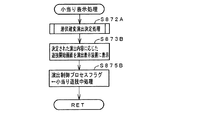
可変表示制御手段は、特殊遊技状態に移行すると決定されたときに特別演出(例えば、図59に示す画像を演出表示装置9に表示させる演出)を実行制御可能であり(例えば、演出制御用マイクロコンピュータ100がステップS873Bの処理を実行する)、可変表示制御手段は、特別遊技状態に制御されているか否かに応じて、第1始動領域を遊技媒体が通過したことにもとづいて特殊遊技状態に移行する場合と、第2始動領域を遊技媒体が通過したことにもとづいて特殊遊技状態に移行する場合とで、異なる割合で特別演出を実行制御する(例えば、演出制御用マイクロコンピュータ100が図62(A),(B)に示すテーブルを参照して、ステップS872A,873Bの処理を実行する)ように構成されていてもよい。
The variable display control means can execute and control a special effect (for example, an effect for displaying the image shown in FIG. 59 on the effect display device 9) when it is determined to shift to the special game state (for example, an effect control micro). When the
可変表示制御手段は、特殊遊技状態に移行すると決定されたときに特別演出(例えば、図59に示す演出)を実行制御可能であり(例えば、演出制御用マイクロコンピュータ100がステップS873Bの処理を実行する)、事前決定手段は、特別可変入賞装置の開放パターンを決定可能であり(例えば、遊技制御用マイクロコンピュータ560が、ステップS62の処理で、図9(B)に示すテーブルにもとづいて、ランダムRの値に応じて、開放パターンAとするか、開放パターンBとするか決定する)、開放パターンと特別演出との組合せは特別遊技状態に制御されているか否かに応じて、異なる割合で決定される(例えば、演出制御用マイクロコンピュータ100が、図55(A),(B)に示すテーブルを参照して、ステップS872A,873Bの処理を実行する)ように構成されていてもよい。
The variable display control means can execute and control a special effect (for example, the effect shown in FIG. 59) when it is determined to shift to the special game state (for example, the
可変表示制御手段は、特別演出の実行制御開始後は、所定のタイミングまで当該特別演出に関係した演出を実行制御可能である(例えば、図60に示す画像を演出表示装置9に表示させる演出を継続する)ように構成されていてもよい。 After the execution control of the special effect is started, the variable display control unit can execute and control an effect related to the special effect until a predetermined timing (for example, an effect for displaying the image shown in FIG. 60 on the effect display device 9). May be configured to continue).
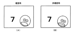
演出表示部に表示される識別情報に所定のキャラクタを異なる態様でそれぞれ表示させるためのキャラクタ画像データ(例えば、図61(A),(B)に示すキャラクタをそれぞれ演出表示装置9に表示させるためのキャラクタ画像データ)がそれぞれ用意され、可変表示制御手段は、特別遊技状態であるか否かにもとづいて、異なるキャラクタ画像データを用いた特別演出を実行制御する(例えば、演出制御用マイクロコンピュータ100が、演出フラグがセットされている場合に、ステップS822の処理で、確変状態フラグがセットされているか否かにもとづいて、図61(A),(B)に示すキャラクタの画像のいずれかを演出表示装置9に表示させるためのプロセステーブルを選択し、選択したプロセステーブルにもとづいて、ステップS823,S824,S841〜S845の処理を実行する)ように構成されていてもよい。
Character image data (for example, characters shown in FIGS. 61 (A) and 61 (B) for displaying a predetermined character in different forms in the identification information displayed on the effect display unit respectively on the
可変表示制御手段は、事前決定手段によって、第2特定遊技状態に移行させると決定された場合と、特殊遊技状態に移行させると決定された場合とで、演出表示部に、同様な演出表示の実行制御が可能である(例えば、演出制御用マイクロコンピュータ100が、突然確変大当りと決定された場合に実行される突確表示処理(ステップS807)と、小当りと決定された場合に実行される小当り表示処理(ステップS810)とにおいて、いずれも潜伏確変演出決定処理(ステップS872A)で実行する演出を決定し、当該決定内容にもとづいて、突然確変大当りと決定された場合にはステップS873Aの処理を実行し、小当りと決定された場合にはステップS873Bの処理を実行する)ように構成されていてもよい。
The variable display control means displays the same effect display on the effect display unit when the advance determination means determines to shift to the second specific gaming state and when to shift to the special gaming state. Execution control is possible (for example, the suddenness display processing (step S807) executed when the
事前決定手段は、第1始動領域を遊技媒体が通過した場合と、第2始動領域を遊技媒体が通過した場合とで、異なる割合で第2特定遊技状態に移行させると決定する(例えば、遊技制御用マイクロコンピュータ560が、ステップS72の処理で、特別図柄ポインタが「第1」を示している場合には、図9(C)に示す第1特別図柄用の大当り種別判定用テーブル131aを選択し、特別図柄ポインタが「第2」を示している場合には、図9(D)に示す第2特別図柄用の大当り種別判定用テーブル131bを選択して、ステップS73の処理で突然確変大当りとするか否か決定する)ように構成されていてもよい。
The pre-determining means determines to shift to the second specific gaming state at a different rate when the game medium passes through the first start area and when the game medium passes through the second start area (for example, game When the special microcomputer pointer indicates “first” in the process of step S72, the
本発明による遊技機は、第1始動領域を遊技媒体が通過したことにもとづいて第1識別情報の可変表示を開始し表示結果を導出表示する第1可変表示手段と、第2始動領域を遊技媒体が通過したことにもとづいて第2識別情報の可変表示を開始し表示結果を導出表示する第2可変表示手段と、遊技者にとって有利な第1状態と遊技者にとって不利な第2状態とに変化する特別可変入賞装置とを有し、第1可変表示手段と第2可変表示手段とのいずれかに特定表示結果が導出表示されたときに遊技者にとって有利な特定遊技状態に移行させるとともに、所定条件が成立したときに通常状態であるときに比べて遊技者にとって有利な特別遊技状態に移行させる遊技機であって、特定遊技状態には特別可変入賞装置を第1期間第1状態に変化させる第1特定遊技状態と、特別可変入賞装置を第1期間よりも短い第2期間第1状態に変化させる第2特定遊技状態とがあり、第1可変表示手段における第1識別情報の可変表示または第2可変表示手段における第2識別情報の可変表示に対応した演出識別情報の可変表示が実行される演出表示部と、第1始動領域を遊技媒体が通過したこと、または第2始動領域を遊技媒体が通過したことにもとづいて、特定遊技状態に移行させるか否かと、特定遊技状態に移行させるときに第1特定遊技状態と第2特定遊技状態とのいずれに移行させるかと、特別遊技状態に移行させるか否かと、特定遊技状態とは異なる特殊遊技状態に移行させるか否かとを表示結果の導出表示以前に決定する事前決定手段と、事前決定手段によって特定表示結果としない旨の決定がなされたことにもとづいて、演出識別情報の可変表示状態を所定のリーチ状態とするか否かを決定するリーチ決定手段と、リーチ決定手段による決定結果にもとづいて、演出識別情報の変動パターン種別を複数種類のいずれかに決定する変動パターン種別決定手段と、変動パターン種別決定手段により決定された変動パターン種別に含まれる変動パターンの中から演出識別情報の変動パターンを決定する変動パターン決定手段と、変動パターン決定手段によって決定された変動パターンにもとづいて、演出表示部を制御する可変表示制御手段と、第2特定遊技状態への制御が終了したときに、特別遊技状態に移行させる制御を行うとともに、特殊遊技状態への制御が終了したときには、当該特殊遊技状態への制御が開始される直前の遊技状態を継続させる制御を行う遊技状態制御手段とを備え、特別可変入賞装置は、特殊遊技状態中に、第1状態に第2期間変化し、事前決定手段は、第1始動領域を遊技媒体が通過した場合と第2始動領域を遊技媒体が通過した場合とで、異なる割合で特殊遊技状態に移行させると決定するように構成されているので、特別可変入賞装置が第2特定遊技状態に制御されている第2期間中と、特殊遊技状態中とで、同様なタイミングで第1状態と第2状態とに変化するように構成され、変動パターン種別決定手段と変動パターン決定手段とを用いて識別情報の変動パターンを決定するように構成されているので、遊技機の設計変更の際に、変更したい変動種別についてのみ変更することが可能になり、設計変更が容易になる。 The gaming machine according to the present invention has a first variable display means for starting variable display of the first identification information based on the fact that the game medium has passed through the first start area and deriving and displaying the display result, and a game in the second start area. Based on the passage of the medium, the second variable display means for starting the variable display of the second identification information and deriving and displaying the display result, and the first state advantageous to the player and the second state disadvantageous to the player A special variable winning device that changes, and when a specific display result is derived and displayed on either the first variable display means or the second variable display means, the player shifts to a specific gaming state that is advantageous to the player, A gaming machine that shifts to a special gaming state that is more advantageous to the player than when it is in a normal state when a predetermined condition is satisfied, and the special variable winning device is changed to a first state for a first period in the specific gaming state Make There are one specific game state and a second specific game state in which the special variable winning device is changed to the first state in the second period shorter than the first period, and the variable display of the first identification information in the first variable display means or the first An effect display unit that performs variable display of the effect identification information corresponding to the variable display of the second identification information in the two variable display means, and that the game medium has passed through the first start area, or the game medium in the second start area Based on the fact that the game has passed, whether to shift to the specific gaming state, whether to shift to the first specific gaming state or the second specific gaming state when shifting to the specific gaming state, shift to the special gaming state Whether or not to make a transition to a special gaming state different from the specific gaming state, prior determination means for determining prior to display display of the display result, and that the specific display result is not determined by the prior determination means Reach determining means for determining whether or not the variable display state of the effect identification information is set to a predetermined reach state based on the determination made, and the variation pattern of the effect identification information based on the determination result by the reach determining means Variation pattern type determining means for determining one of a plurality of types, and variation pattern determining means for determining the variation pattern of the production identification information from the variation patterns included in the variation pattern type determined by the variation pattern type determining unit And variable display control means for controlling the effect display section based on the variation pattern determined by the variation pattern determination means, and control for shifting to the special gaming state when the control to the second specific gaming state is completed. And when the control to the special gaming state is finished, the game immediately before the control to the special gaming state is started. And a special variable winning device that changes to the first state during the second period during the special gaming state, and the predetermining means moves the first start area to the game medium. Is determined to shift to the special gaming state at a different rate depending on whether the game medium has passed through the second starting area or the game medium has passed through the second starting area. It is configured to change between the first state and the second state at the same timing between the controlled second period and the special gaming state, and uses the variation pattern type determination unit and the variation pattern determination unit. Therefore, when the design of the gaming machine is changed, it is possible to change only the type of change that is desired to be changed, and the design can be easily changed.
請求項2記載の発明では、可変表示制御手段は、特殊遊技状態に移行すると決定されたときに特別演出を実行制御可能であり、可変表示制御手段は、特別遊技状態に制御されているか否かに応じて、第1始動領域を遊技媒体が通過したことにもとづいて特殊遊技状態に移行する場合と、第2始動領域を遊技媒体が通過したことにもとづいて特殊遊技状態に移行する場合とで、異なる割合で特別演出を実行制御するように構成されているので、遊技媒体が通過した始動領域と、実行される特別演出との組合せに応じて、遊技者の特別遊技状態であることへの期待度を異ならせ、遊技興趣を向上させることができる。
In the invention according to
請求項3記載の発明では、可変表示制御手段は、特殊遊技状態に移行すると決定されたときに特別演出を実行制御可能であり、事前決定手段は、特別可変入賞装置の開放パターンを決定可能であり、開放パターンと特別演出との組合せは特別遊技状態に制御されているか否かに応じて、異なる割合で決定されるように構成されているので、特別可変入賞装置の動作パターンと実行される特別演出との組合せに応じて、遊技者の特別遊技状態であることへの期待度を異ならせ、遊技興趣を向上させることができる。
In the invention according to
請求項4記載の発明では、可変表示制御手段は、特別演出の実行制御開始後は、所定のタイミングまで当該特別演出に関係した演出を実行制御可能であるので、演出の幅を広げ、遊技興趣を向上させることができる。
In the invention according to
請求項5記載の発明では、演出表示部に表示される識別情報に所定のキャラクタを異なる態様でそれぞれ表示させるためのキャラクタ画像データがそれぞれ用意され、可変表示制御手段は、特別遊技状態であるか否かにもとづいて、異なるキャラクタ画像データを用いた特別演出を実行制御するように構成されているので、演出の幅を広げ、遊技興趣を向上させることができる。 According to the fifth aspect of the present invention, character image data for displaying the predetermined character in different modes is prepared in the identification information displayed on the effect display unit, and the variable display control means is in a special game state. Since it is configured to execute and control a special effect using different character image data based on whether or not, it is possible to widen the range of effects and improve the game entertainment.
請求項6記載の発明では、可変表示制御手段は、事前決定手段によって、第2特定遊技状態に移行させると決定された場合と、特殊遊技状態に移行させると決定された場合とで、演出表示部に、同様な演出表示の実行制御が可能であるように構成されているので、遊技者による特定遊技状態であるのか否かの認識を困難にし、遊技興趣を向上させることができる。
In the invention described in
請求項7記載の発明では、事前決定手段は、第1始動領域を遊技媒体が通過した場合と、第2始動領域を遊技媒体が通過した場合とで、異なる割合で第2特定遊技状態に移行させると決定するように構成されているので、遊技媒体が通過した始動領域に応じて、遊技者の第2特定遊技状態に移行することへの期待度を異ならせ、遊技興趣を向上させることができる。
In the invention according to
以下、本発明の実施の形態を、図面を参照して説明する。まず、遊技機の一例であるパチンコ遊技機1の全体の構成について説明する。図1はパチンコ遊技機1を正面からみた正面図である。
Hereinafter, embodiments of the present invention will be described with reference to the drawings. First, the overall configuration of a
パチンコ遊技機1は、縦長の方形状に形成された外枠(図示せず)と、外枠の内側に開閉可能に取り付けられた遊技枠とで構成される。また、パチンコ遊技機1は、遊技枠に開閉可能に設けられている額縁状に形成されたガラス扉枠2を有する。遊技枠は、外枠に対して開閉自在に設置される前面枠(図示せず)と、機構部品等が取り付けられる機構板(図示せず)と、それらに取り付けられる種々の部品(後述する遊技盤6を除く)とを含む構造体である。
The
ガラス扉枠2の下部表面には打球供給皿(上皿)3がある。打球供給皿3の下部には、打球供給皿3に収容しきれない遊技球を貯留する余剰球受皿4や、打球を発射する打球操作ハンドル(操作ノブ)5が設けられている。また、ガラス扉枠2の背面には、遊技盤6が着脱可能に取り付けられている。なお、遊技盤6は、それを構成する板状体と、その板状体に取り付けられた種々の部品とを含む構造体である。また、遊技盤6の前面には、打ち込まれた遊技球が流下可能な遊技領域7が形成されている。
On the lower surface of the
遊技領域7の中央付近には、液晶表示装置(LCD)で構成された演出表示装置9が設けられている。演出表示装置9では、第1特別図柄または第2特別図柄の可変表示に同期した演出図柄(飾り図柄)の可変表示(変動)が行われる。よって、演出表示装置9は、識別情報としての演出図柄(飾り図柄)の可変表示を行う可変表示装置に相当する。演出表示装置9は、演出制御基板に搭載されている演出制御用マイクロコンピュータによって制御される。演出制御用マイクロコンピュータが、第1特別図柄表示器8aで第1特別図柄の可変表示が実行されているときに、その可変表示に伴って演出表示装置9で演出表示を実行させ、第2特別図柄表示器8bで第2特別図柄の可変表示が実行されているときに、その可変表示に伴って演出表示装置で演出表示を実行させるので、遊技の進行状況を把握しやすくすることができる。
An
遊技盤6における演出表示装置9の上部の左側には、識別情報としての第1特別図柄を可変表示する第1特別図柄表示器(第1可変表示手段)8aが設けられている。この実施の形態では、第1特別図柄表示器8aは、0〜9の数字を可変表示可能な簡易で小型の表示器(例えば7セグメントLED)で実現されている。すなわち、第1特別図柄表示器8aは、0〜9の数字(または、記号)を可変表示するように構成されている。遊技盤6における演出表示装置9の上部の右側には、識別情報としての第2特別図柄を可変表示する第2特別図柄表示器(第2可変表示手段)8bが設けられている。第2特別図柄表示器8bは、0〜9の数字を可変表示可能な簡易で小型の表示器(例えば7セグメントLED)で実現されている。すなわち、第2特別図柄表示器8bは、0〜9の数字(または、記号)を可変表示するように構成されている。
A first special symbol display (first variable display means) 8 a that variably displays a first special symbol as identification information is provided on the left side of the top of the
この実施の形態では、第1特別図柄の種類と第2特別図柄の種類とは同じ(例えば、ともに0〜9の数字)であるが、種類が異なっていてもよい。また、第1特別図柄表示器8aおよび第2特別図柄表示器8bは、それぞれ、例えば、00〜99の数字(または、2桁の記号)を可変表示するように構成されていてもよい。
In this embodiment, the type of the first special symbol and the type of the second special symbol are the same (for example, both 0 to 9), but the types may be different. The first
以下、第1特別図柄と第2特別図柄とを特別図柄と総称することがあり、第1特別図柄表示器8aと第2特別図柄表示器8bとを特別図柄表示器と総称することがある。
Hereinafter, the first special symbol and the second special symbol may be collectively referred to as a special symbol, and the first
第1特別図柄または第2特別図柄の可変表示は、可変表示の実行条件である第1始動条件または第2始動条件が成立(例えば、遊技球が第1始動入賞口13または第2始動入賞口14に入賞したこと)した後、可変表示の開始条件(例えば、保留記憶数が0でない場合であって、第1特別図柄および第2特別図柄の可変表示が実行されていない状態であり、かつ、大当り遊技が実行されていない状態)が成立したことにもとづいて開始され、可変表示時間(変動時間)が経過すると表示結果(停止図柄)を導出表示する。なお、入賞とは、入賞口などのあらかじめ入賞領域として定められている領域に遊技球が入ったことである。また、表示結果を導出表示するとは、図柄(識別情報の例)を最終的に停止表示させることである。
For the variable display of the first special symbol or the second special symbol, the first start condition or the second start condition, which is the variable display execution condition, is satisfied (for example, the game ball has the first
演出表示装置9は、第1特別図柄表示器8aでの第1特別図柄の可変表示時間中、および第2特別図柄表示器8bでの第2特別図柄の可変表示時間中に、装飾用(演出用)の図柄としての演出図柄(飾り図柄)の可変表示を行う。第1特別図柄表示器8aにおける第1特別図柄の可変表示と、演出表示装置9における演出図柄の可変表示とは同期している。また、第2特別図柄表示器8bにおける第2特別図柄の可変表示と、演出表示装置9における演出図柄の可変表示とは同期している。同期とは、可変表示の開始時点および終了時点がほぼ同じ(全く同じでもよい。)であって、可変表示の期間がほぼ同じ(全く同じでもよい。)であることをいう。また、第1特別図柄表示器8aにおいて大当り図柄が停止表示されるときと、第2特別図柄表示器8bにおいて大当り図柄が停止表示されるときには、演出表示装置9において大当りを想起させるような演出図柄の組み合わせが停止表示される。
The
演出表示装置9の下方には、第1始動入賞口13を有する入賞装置が設けられている。第1始動入賞口13に入賞した遊技球は、遊技盤6の背面に導かれ、第1始動口スイッチ13aによって検出される。
A winning device having a first
また、第1始動入賞口(第1始動口)13を有する入賞装置の下方には、遊技球が入賞可能な第2始動入賞口14を有する可変入賞球装置15が設けられている。第2始動入賞口(第2始動口)14に入賞した遊技球は、遊技盤6の背面に導かれ、第2始動口スイッチ14aによって検出される。可変入賞球装置15は、ソレノイド16によって開状態とされる。可変入賞球装置15が開状態になることによって、遊技球が第2始動入賞口14に入賞可能になり(始動入賞し易くなり)、遊技者にとって有利な状態になる。可変入賞球装置15が開状態になっている状態では、第1始動入賞口13よりも、第2始動入賞口14に遊技球が入賞しやすい。また、可変入賞球装置15が閉状態になっている状態では、遊技球は第2始動入賞口14に入賞しない。なお、可変入賞球装置15が閉状態になっている状態において、入賞はしづらいものの、入賞することは可能である(すなわち、遊技球が入賞しにくい)ように構成されていてもよい。
A variable winning
以下、第1始動入賞口13と第2始動入賞口14とを総称して始動入賞口または始動口ということがある。
Hereinafter, the first
可変入賞球装置15が開放状態に制御されているときには可変入賞球装置15に向かう遊技球は第2始動入賞口14に極めて入賞しやすい。そして、第1始動入賞口13は演出表示装置9の直下に設けられているが、演出表示装置9の下端と第1始動入賞口13との間の間隔をさらに狭めたり、第1始動入賞口13の周辺で釘を密に配置したり、第1始動入賞口13の周辺での釘配列を遊技球を第1始動入賞口13に導きづらくして、第2始動入賞口14の入賞率の方を第1始動入賞口13の入賞率よりもより高くするようにしてもよい。
When the variable winning
第1特別図柄表示器8aの下部には、第1始動入賞口13に入った有効入賞球数すなわち第1保留記憶数(保留記憶を、始動記憶または始動入賞記憶ともいう。)を表示する4つの表示器(例えば、LED)からなる第1特別図柄保留記憶表示器18aが設けられている。第1特別図柄保留記憶表示器18aは、有効始動入賞がある毎に、点灯する表示器の数を1増やす。そして、第1特別図柄表示器8aでの可変表示が開始される毎に、点灯する表示器の数を1減らす。
Below the first
第2特別図柄表示器8bの下部には、第2始動入賞口14に入った有効入賞球数すなわち第2保留記憶数を表示する4つの表示器(例えば、LED)からなる第2特別図柄保留記憶表示器18bが設けられている。第2特別図柄保留記憶表示器18bは、有効始動入賞がある毎に、点灯する表示器の数を1増やす。そして、第2特別図柄表示器8bでの可変表示が開始される毎に、点灯する表示器の数を1減らす。
Below the second special symbol display 8b is a second special symbol hold comprising four indicators (for example, LEDs) for displaying the number of effective winning balls that have entered the second
また、演出表示装置9の表示画面には、第1保留記憶数と第2保留記憶数との合計である合計数(合算保留記憶数)を表示する領域(以下、合算保留記憶表示部18cという。)が設けられている。合計数を表示する合算保留記憶表示部18cが設けられているので、可変表示の開始条件が成立していない実行条件の成立数の合計を把握しやすくすることができる。なお、第1特別図柄保留記憶表示器18aおよび第2特別図柄保留記憶表示器18bのみを設けるようにし、演出表示装置9の表示画面上には合算保留記憶表示部18cを設けないようにしてもよい。
In addition, the display screen of the
なお、この実施の形態では、図1に示すように、第2始動入賞口14に対してのみ開閉動作を行う可変入賞球装置15が設けられているが、第1始動入賞口13および第2始動入賞口14のいずれについても開閉動作を行う可変入賞球装置が設けられている構成であってもよい。
In this embodiment, as shown in FIG. 1, the variable winning
また、図1に示すように、可変入賞球装置15の下方には、特別可変入賞球装置20が設けられている。特別可変入賞球装置20は開閉板を備え、第1特別図柄表示器8aに特定表示結果(大当り図柄)が導出表示されたとき、および第2特別図柄表示器8bに特定表示結果(大当り図柄)が導出表示されたときに生起する特定遊技状態(大当り遊技状態)においてソレノイド21によって開閉板が開放状態に制御されることによって、入賞領域となる大入賞口が開放状態になる。大入賞口に入賞した遊技球はカウントスイッチ23で検出される。
Further, as shown in FIG. 1, a special variable winning
遊技盤6の右側方下部には、普通図柄表示器10が設けられている。普通図柄表示器10は、普通図柄と呼ばれる複数種類の識別情報(例えば、「○」および「×」)を可変表示する。
A
遊技球がゲート32を通過しゲートスイッチ32aで検出されると、普通図柄表示器10の表示の可変表示が開始される。この実施の形態では、上下のランプ(点灯時に図柄が視認可能になる)が交互に点灯することによって可変表示が行われ、例えば、可変表示の終了時に下側のランプが点灯すれば当りとなる。そして、普通図柄表示器10における停止図柄が所定の図柄(当り図柄)である場合に、可変入賞球装置15が所定回数、所定時間だけ開状態になる。すなわち、可変入賞球装置15の状態は、普通図柄の停止図柄が当り図柄である場合に、遊技者にとって不利な状態から有利な状態(第2始動入賞口14に遊技球が入賞可能な状態)に変化する。普通図柄表示器10の近傍には、ゲート32を通過した入賞球数を表示する4つの表示器(例えば、LED)を有する普通図柄保留記憶表示器41が設けられている。ゲート32への遊技球の通過がある毎に、すなわちゲートスイッチ32aによって遊技球が検出される毎に、普通図柄保留記憶表示器41は点灯する表示器を1増やす。そして、普通図柄表示器10の可変表示が開始される毎に、点灯する表示器を1減らす。さらに、通常状態に比べて大当りとすることに決定される確率が高い状態である確変状態では、普通図柄表示器10における停止図柄が当り図柄になる確率が高められるとともに、可変入賞球装置15の開放時間が長くなり、かつ、開放回数が増加される。すなわち、遊技球が始動入賞しやすくなる(つまり、特別図柄表示器8a,8bや演出表示装置9における可変表示の実行条件が成立しやすくなる)ように制御された遊技状態である高ベース状態に移行する。また、この実施の形態では、時短状態(特別図柄の可変表示時間が短縮される遊技状態)においても、可変入賞球装置15の開放時間が長くなり、かつ、開放回数が増加される。
When the game ball passes through the
なお、可変入賞球装置15が開状態となる時間を延長する(開放延長状態ともいう)のでなく、普通図柄表示器10における停止図柄が当り図柄になる確率が高められる普通図柄確変状態に移行することによって、高ベース状態に移行してもよい。普通図柄表示器10における停止図柄が所定の図柄(当り図柄)となると、可変入賞球装置15が所定回数、所定時間だけ開状態になる。この場合、普通図柄確変状態に移行制御することによって、普通図柄表示器10における停止図柄が当り図柄になる確率が高められ、可変入賞球装置15が開状態となる頻度が高まる。従って、普通図柄確変状態に移行すれば、可変入賞球装置15の開放時間と開放回数が高められ、始動入賞しやすい状態(高ベース状態)となる。すなわち、可変入賞球装置15の開放時間と開放回数は、普通図柄の停止図柄が当り図柄であったり、特別図柄の停止図柄が確変図柄である場合等に高められ、遊技者にとって不利な状態から有利な状態(始動入賞しやすい状態)に変化する。なお、開放回数が高められることは、閉状態から開状態になることも含む概念である。
Instead of extending the time during which the variable winning
また、普通図柄表示器10における普通図柄の変動時間(可変表示期間)が短縮される普通図柄時短状態に移行することによって、高ベース状態に移行してもよい。普通図柄時短状態では、普通図柄の変動時間が短縮されるので、普通図柄の変動が開始される頻度が高くなり、結果として普通図柄が当りとなる頻度が高くなる。従って、普通図柄が当りとなる頻度が高くなることによって、可変入賞球装置15が開状態となる頻度が高くなり、始動入賞しやすい状態(高ベース状態)となる。
Moreover, you may transfer to a high base state by shifting to the normal symbol time short state where the fluctuation time (variable display period) of the normal symbol in the
また、特別図柄や演出図柄の変動時間(可変表示期間)が短縮される時短状態に移行することによって、特別図柄や演出図柄の変動時間が短縮されるので、特別図柄や演出図柄の変動が開始される頻度が高くなり(換言すれば、保留記憶の消化が速くなる。)、結果として、始動入賞しやすくなり大当り遊技が行われる可能性が高まる。 In addition, the transition time of special symbols and production symbols will be shortened by shifting to the short time state when the variation time (variable display period) of special symbols and production symbols will be shortened. (In other words, the digestion of the reserved memory becomes faster), and as a result, it is easier to start a prize and the possibility of playing a big hit game is increased.
さらに、上記に示した全ての状態(開放延長状態、普通図柄確変状態、普通図柄時短状態および特別図柄時短状態)に移行させることによって、始動入賞しやすくなる(高ベース状態に移行する)ようにしてもよい。また、上記に示した各状態(開放延長状態、普通図柄確変状態、普通図柄時短状態および特別図柄時短状態)のうちのいずれか複数の状態に移行させることによって、始動入賞しやすくなる(高ベース状態に移行する)ようにしてもよい。 Furthermore, by shifting to all the states shown above (open extended state, normal symbol probability changing state, normal symbol short time state, and special symbol short time state), it will be easier to win a start (shift to a high base state). May be. In addition, it is easier to win a start (high base) by shifting to any one of the above states (open extended state, normal symbol probability changing state, normal symbol short time state, and special symbol short time state). Transition to a state).
遊技盤6の遊技領域7の左右周辺には、遊技中に点滅表示される装飾LED25が設けられ、下部には、入賞しなかった打球が取り込まれるアウト口26がある。また、遊技領域7の外側の左右上部には、所定の音声出力として効果音や音声を発声する2つのスピーカ27R,27Lが設けられている。遊技領域7の外周上部、外周左部および外周右部には、前面枠に設けられた天枠LED28a、左枠LED28bおよび右枠LED28cが設けられている。また、左枠LED28bの近傍には賞球残数があるときに点灯する賞球LED51が設けられ、右枠LED28cの近傍には補給球が切れたときに点灯する球切れLED52が設けられている。天枠LED28a、左枠LED28bおよび右枠LED28cおよび装飾用LED25は、パチンコ遊技機1に設けられている演出用の発光体の一例である。なお、上述した演出用(装飾用)の各種LEDの他にも演出のためのLEDやランプが設置されている。
On the left and right sides of the
遊技機には、遊技者が打球操作ハンドル5を操作することに応じて駆動モータを駆動し、駆動モータの回転力を利用して遊技球を遊技領域7に発射する打球発射装置(図示せず)が設けられている。打球発射装置から発射された遊技球は、遊技領域7を囲むように円形状に形成された打球レールを通って遊技領域7に入り、その後、遊技領域7を下りてくる。遊技球が第1始動入賞口13に入り第1始動口スイッチ13aで検出されると、第1特別図柄の可変表示を開始できる状態であれば(例えば、特別図柄の可変表示が終了し、第1の開始条件が成立したこと)、第1特別図柄表示器8aにおいて第1特別図柄の可変表示(変動)が開始されるとともに、演出表示装置9において演出図柄(飾り図柄)の可変表示が開始される。すなわち、第1特別図柄および演出図柄の可変表示は、第1始動入賞口13への入賞に対応する。第1特別図柄の可変表示を開始できる状態でなければ、第1保留記憶数が上限値に達していないことを条件として、第1保留記憶数を1増やす。
In the gaming machine, a ball striking device (not shown) that drives a driving motor in response to a player operating the batting operation handle 5 and uses the rotational force of the driving motor to launch a gaming ball to the gaming area 7. ) Is provided. A game ball launched from the ball striking device enters the
遊技球が第2始動入賞口14に入り第2始動口スイッチ14aで検出されると、第2特別図柄の可変表示を開始できる状態であれば(例えば、特別図柄の可変表示が終了し、第2の開始条件が成立したこと)、第2特別図柄表示器8bにおいて第2特別図柄の可変表示(変動)が開始されるとともに、演出表示装置9において演出図柄(飾り図柄)の可変表示が開始される。すなわち、第2特別図柄および演出図柄の可変表示は、第2始動入賞口14への入賞に対応する。第2特別図柄の可変表示を開始できる状態でなければ、第2保留記憶数が上限値に達していないことを条件として、第2保留記憶数を1増やす。
When the game ball enters the second
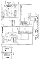
図2は、主基板(遊技制御基板)31における回路構成の一例を示すブロック図である。なお、図2には、払出制御基板37および演出制御基板80等も示されている。主基板31には、プログラムに従ってパチンコ遊技機1を制御する遊技制御用マイクロコンピュータ(遊技制御手段に相当)560が搭載されている。遊技制御用マイクロコンピュータ560は、ゲーム制御(遊技進行制御)用のプログラム等を記憶するROM54、ワークメモリとして使用される記憶手段としてのRAM55、プログラムに従って制御動作を行うCPU56およびI/Oポート部57を含む。この実施の形態では、ROM54およびRAM55は遊技制御用マイクロコンピュータ560に内蔵されている。すなわち、遊技制御用マイクロコンピュータ560は、1チップマイクロコンピュータである。1チップマイクロコンピュータには、少なくともCPU56のほかRAM55が内蔵されていればよく、ROM54は外付けであっても内蔵されていてもよい。また、I/Oポート部57は、外付けであってもよい。遊技制御用マイクロコンピュータ560には、さらに、ハードウェア乱数(ハードウェア回路が発生する乱数)を発生する乱数回路503が内蔵されている。
FIG. 2 is a block diagram showing an example of the circuit configuration of the main board (game control board) 31. 2 also shows the
なお、遊技制御用マイクロコンピュータ560においてCPU56がROM54に格納されているプログラムに従って制御を実行するので、以下、遊技制御用マイクロコンピュータ560(またはCPU56)が実行する(または、処理を行う)ということは、具体的には、CPU56がプログラムに従って制御を実行することである。このことは、主基板31以外の他の基板に搭載されているマイクロコンピュータについても同様である。
In the
乱数回路503は、特別図柄の可変表示の表示結果により大当りとするか否か判定するための判定用の乱数を発生するために用いられるハードウェア回路である。乱数回路503は、初期値(例えば、0)と上限値(例えば、65535)とが設定された数値範囲内で、数値データを、設定された更新規則に従って更新し、ランダムなタイミングで発生する始動入賞時が数値データの読出(抽出)時であることにもとづいて、読出される数値データが乱数値となる乱数発生機能を有する。
The
乱数回路503は、数値データの更新範囲の選択設定機能(初期値の選択設定機能、および、上限値の選択設定機能)、数値データの更新規則の選択設定機能、および数値データの更新規則の選択切換え機能等の各種の機能を有する。このような機能によって、生成する乱数のランダム性を向上させることができる。
The
また、遊技制御用マイクロコンピュータ560は、乱数回路503が更新する数値データの初期値を設定する機能を有している。例えば、ROM54等の所定の記憶領域に記憶された遊技制御用マイクロコンピュータ560のIDナンバ(遊技制御用マイクロコンピュータ560の各製品ごとに異なる数値で付与されたIDナンバ)を用いて所定の演算を行なって得られた数値データを、乱数回路503が更新する数値データの初期値として設定する。そのような処理を行うことによって、乱数回路503が発生する乱数のランダム性をより向上させることができる。
Further, the
遊技制御用マイクロコンピュータ560は、第1始動口スイッチ13aまたは第2始動口スイッチ14aへの始動入賞が生じたときに乱数回路503から数値データをランダムRとして読み出し、ランダムRにもとづいて特定の表示結果としての大当り表示結果にするか否か、すなわち、大当りとするか否かを判定する。そして、大当りとすると判定したときに、遊技状態を遊技者にとって有利な特定遊技状態としての大当り遊技状態に移行させる。
The
また、RAM55は、その一部または全部が電源基板において作成されるバックアップ電源によってバックアップされている不揮発性記憶手段としてのバックアップRAMである。すなわち、遊技機に対する電力供給が停止しても、所定期間(バックアップ電源としてのコンデンサが放電してバックアップ電源が電力供給不能になるまで)は、RAM55の一部または全部の内容は保存される。特に、少なくとも、遊技状態すなわち遊技制御手段の制御状態に応じたデータ(特別図柄プロセスフラグや合算保留記憶数カウンタの値など)と未払出賞球数を示すデータは、バックアップRAMに保存される。遊技制御手段の制御状態に応じたデータとは、停電等が生じた後に復旧した場合に、そのデータにもとづいて、制御状態を停電等の発生前に復旧させるために必要なデータである。また、制御状態に応じたデータと未払出賞球数を示すデータとを遊技の進行状態を示すデータと定義する。なお、この実施の形態では、RAM55の全部が、電源バックアップされているとする。
The
遊技制御用マイクロコンピュータ560のリセット端子には、電源基板からのリセット信号(図示せず)が入力される。電源基板には、遊技制御用マイクロコンピュータ560等に供給されるリセット信号を生成するリセット回路が搭載されている。なお、リセット信号がハイレベルになると遊技制御用マイクロコンピュータ560等は動作可能状態になり、リセット信号がローレベルになると遊技制御用マイクロコンピュータ560等は動作停止状態になる。従って、リセット信号がハイレベルである期間は、遊技制御用マイクロコンピュータ560等の動作を許容する許容信号が出力されていることになり、リセット信号がローレベルである期間は、遊技制御用マイクロコンピュータ560等の動作を停止させる動作停止信号が出力されていることになる。なお、リセット回路をそれぞれの電気部品制御基板(電気部品を制御するためのマイクロコンピュータが搭載されている基板)に搭載してもよい。
A reset signal (not shown) from the power supply board is input to the reset terminal of the
さらに、遊技制御用マイクロコンピュータ560の入力ポートには、電源基板からの電源電圧が所定値以下に低下したことを示す電源断信号が入力される。すなわち、電源基板には、遊技機において使用される所定電圧(例えば、DC30VやDC5Vなど)の電圧値を監視して、電圧値があらかじめ定められた所定値にまで低下すると(電源電圧の低下を検出すると)、その旨を示す電源断信号を出力する電源監視回路が搭載されている。また、遊技制御用マイクロコンピュータ560の入力ポートには、RAMの内容をクリアすることを指示するためのクリアスイッチが操作されたことを示すクリア信号(図示せず)が入力される。
Further, a power-off signal indicating that the power supply voltage from the power supply board has dropped below a predetermined value is input to the input port of the
また、ゲートスイッチ32a、第1始動口スイッチ13a、第2始動口スイッチ14aおよびカウントスイッチ23からの検出信号を遊技制御用マイクロコンピュータ560に与える入力ドライバ回路58も主基板31に搭載されている。また、可変入賞球装置15を開閉するソレノイド16、および大入賞口を形成する特別可変入賞球装置20を開閉するソレノイド21を遊技制御用マイクロコンピュータ560からの指令に従って駆動する出力回路59も主基板31に搭載されている。さらに、大当り遊技状態の発生を示す大当り情報等の情報出力信号をホールコンピュータ等の外部装置に対して出力する情報出力回路(図示せず)も主基板31に搭載されている。
Further, an
この実施の形態では、演出制御基板80に搭載されている演出制御手段(演出制御用マイクロコンピュータで構成される。)が、中継基板77を介して遊技制御用マイクロコンピュータ560から演出内容を指示する演出制御コマンドを受信し、演出図柄を可変表示する演出表示装置9との表示制御を行う。
In this embodiment, the effect control means (configured by the effect control microcomputer) mounted on the
図3は、中継基板77、演出制御基板80、ランプドライバ基板35および音声出力基板70の回路構成例を示すブロック図である。なお、図3に示す例では、ランプドライバ基板35および音声出力基板70には、マイクロコンピュータは搭載されていないが、マイクロコンピュータを搭載してもよい。また、ランプドライバ基板35および音声出力基板70を設けずに、演出制御に関して演出制御基板80のみを設けてもよい。
FIG. 3 is a block diagram illustrating a circuit configuration example of the
演出制御基板80は、演出制御用CPU101およびRAMを含む演出制御用マイクロコンピュータ100を搭載している。なお、RAMは外付けであってもよい。演出制御基板80において、演出制御用CPU101は、内蔵または外付けのROM(図示せず)に格納されたプログラムに従って動作し、中継基板77を介して入力される主基板31からの取込信号(演出制御INT信号)に応じて、入力ドライバ102および入力ポート103を介して演出制御コマンドを受信する。また、演出制御用CPU101は、演出制御コマンドにもとづいて、VDP(ビデオディスプレイプロセッサ)109に演出表示装置9の表示制御を行わせる。
The
この実施の形態では、演出制御用マイクロコンピュータ100と共動して演出表示装置9の表示制御を行うVDP109が演出制御基板80に搭載されている。VDP109は、演出制御用マイクロコンピュータ100とは独立したアドレス空間を有し、そこにVRAMをマッピングする。VRAMは、VDPによって生成された画像データを展開するためのバッファメモリである。そして、VDP109は、VRAM内の画像データを演出表示装置9に出力する。
In this embodiment, a
演出制御用CPU101は、受信した演出制御コマンドに従ってキャラクタROM(図示せず)から必要なデータを読み出す。キャラクタROMは、演出表示装置9に表示されるキャラクタ画像データ、具体的には、人物、文字、図形または記号等(演出図柄を含む)をあらかじめ格納しておくためのものである。演出制御用CPU101は、キャラクタROMから読み出したデータをVDP109に出力する。VDP109は、演出制御用CPU101から入力されたデータにもとづいて表示制御を実行する。
The
演出制御コマンドおよび演出制御INT信号は、演出制御基板80において、まず、入力ドライバ102に入力する。入力ドライバ102は、中継基板77から入力された信号を演出制御基板80の内部に向かう方向にしか通過させない(演出制御基板80の内部から中継基板77への方向には信号を通過させない)信号方向規制手段としての単方向性回路でもある。
The effect control command and the effect control INT signal are first input to the
中継基板77には、主基板31から入力された信号を演出制御基板80に向かう方向にしか通過させない(演出制御基板80から中継基板77への方向には信号を通過させない)信号方向規制手段としての単方向性回路74が搭載されている。単方向性回路として、例えばダイオードやトランジスタが使用される。図3には、ダイオードが例示されている。また、単方向性回路は、各信号毎に設けられる。さらに、単方向性回路である出力ポート571を介して主基板31から演出制御コマンドおよび演出制御INT信号が出力されるので、中継基板77から主基板31の内部に向かう信号が規制される。すなわち、中継基板77からの信号は主基板31の内部(遊技制御用マイクロコンピュータ560側)に入り込まない。なお、出力ポート571は、図2に示されたI/Oポート部57の一部である。また、出力ポート571の外側(中継基板77側)に、さらに、単方向性回路である信号ドライバ回路が設けられていてもよい。
As a signal direction regulating means, the signal inputted from the main board 31 is allowed to pass through the
さらに、演出制御用CPU101は、出力ポート105を介してランプドライバ基板35に対してLEDを駆動する信号を出力する。また、演出制御用CPU101は、出力ポート104を介して音声出力基板70に対して音番号データを出力する。
Further, the
ランプドライバ基板35において、LEDを駆動する信号は、入力ドライバ351を介してLEDドライバ352に入力される。LEDドライバ352は、駆動信号を天枠LED28a、左枠LED28b、右枠LED28cなどの枠側に設けられている各LEDに供給する。また、遊技盤側に設けられている装飾LED25に駆動信号を供給する。なお、LED以外の発光体が設けられている場合には、それを駆動する駆動回路(ドライバ)がランプドライバ基板35に搭載される。
In the
音声出力基板70において、音番号データは、入力ドライバ702を介して音声合成用IC703に入力される。音声合成用IC703は、音番号データに応じた音声や効果音を発生し増幅回路705に出力する。増幅回路705は、音声合成用IC703の出力レベルを、ボリューム706で設定されている音量に応じたレベルに増幅した音声信号をスピーカ27R,27Lに出力する。音声データROM704には、音番号データに応じた制御データが格納されている。音番号データに応じた制御データは、所定期間(例えば演出図柄の変動期間)における効果音または音声の出力態様を時系列的に示すデータの集まりである。
In the
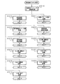
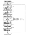
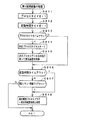
次に、遊技機の動作について説明する。図4は、主基板31における遊技制御用マイクロコンピュータ560が実行するメイン処理を示すフローチャートである。遊技機に対して電源が投入され電力供給が開始されると、リセット信号が入力されるリセット端子の入力レベルがハイレベルになり、遊技制御用マイクロコンピュータ560(具体的には、CPU56)は、プログラムの内容が正当か否か確認するための処理であるセキュリティチェック処理を実行した後、ステップS1以降のメイン処理を開始する。メイン処理において、CPU56は、まず、必要な初期設定を行う。
Next, the operation of the gaming machine will be described. FIG. 4 is a flowchart showing a main process executed by the
初期設定処理において、CPU56は、まず、割込禁止に設定する(ステップS1)。次に、割込モードを割込モード2に設定し(ステップS2)、スタックポインタにスタックポインタ指定アドレスを設定する(ステップS3)。そして、内蔵デバイスの初期化(内蔵デバイス(内蔵周辺回路)であるCTC(カウンタ/タイマ)およびPIO(パラレル入出力ポート)の初期化など)を行った後(ステップS4)、RAMをアクセス可能状態に設定する(ステップS5)。なお、割込モード2は、CPU56が内蔵する特定レジスタ(Iレジスタ)の値(1バイト)と内蔵デバイスが出力する割込ベクタ(1バイト:最下位ビット0)とから合成されるアドレスが、割込番地を示すモードである。
In the initial setting process, the
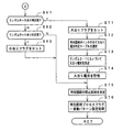
次いで、CPU56は、入力ポートを介して入力されるクリアスイッチ(例えば、電源基板に搭載されている。)の出力信号(クリア信号)の状態を確認する(ステップS6)。その確認においてオンを検出した場合には、CPU56は、通常の初期化処理(ステップS10〜S15)を実行する。
Next, the
クリアスイッチがオンの状態でない場合には、遊技機への電力供給が停止したときにバックアップRAM領域のデータ保護処理(例えばパリティデータの付加等の電力供給停止時処理)が行われたか否か確認する(ステップS7)。そのような保護処理が行われていないことを確認したら、CPU56は初期化処理を実行する。バックアップRAM領域にバックアップデータがあるか否かは、例えば、電力供給停止時処理においてバックアップRAM領域に設定されるバックアップフラグの状態によって確認される。
If the clear switch is not on, check whether data protection processing of the backup RAM area (for example, power supply stop processing such as addition of parity data) was performed when power supply to the gaming machine was stopped (Step S7). When it is confirmed that such protection processing is not performed, the
電力供給停止時処理が行われたことを確認したら、CPU56は、バックアップRAM領域のデータチェックを行う(ステップS8)。この実施の形態では、データチェックとしてパリティチェックを行う。よって、ステップS8では、算出したチェックサムと、電力供給停止時処理で同一の処理によって算出され保存されているチェックサムとを比較する。不測の停電等の電力供給停止が生じた後に復旧した場合には、バックアップRAM領域のデータは保存されているはずであるから、チェック結果(比較結果)は正常(一致)になる。チェック結果が正常でないということは、バックアップRAM領域のデータが、電力供給停止時のデータとは異なっていることを意味する。そのような場合には、内部状態を電力供給停止時の状態に戻すことができないので、電力供給の停止からの復旧時でない電源投入時に実行される初期化処理を実行する。
When it is confirmed that the power supply stop process has been performed, the
チェック結果が正常であれば、CPU56は、遊技制御手段の内部状態と演出制御手段等の電気部品制御手段の制御状態を電力供給停止時の状態に戻すための遊技状態復旧処理(ステップS41〜S43の処理)を行う。具体的には、ROM54に格納されているバックアップ時設定テーブルの先頭アドレスをポインタに設定し(ステップS41)、バックアップ時設定テーブルの内容を順次作業領域(RAM55内の領域)に設定する(ステップS42)。作業領域はバックアップ電源によって電源バックアップされている。バックアップ時設定テーブルには、作業領域のうち初期化してもよい領域についての初期化データが設定されている。ステップS41およびS42の処理によって、作業領域のうち初期化してはならない部分については、保存されていた内容がそのまま残る。初期化してはならない部分とは、例えば、電力供給停止前の遊技状態を示すデータ(特別図柄プロセスフラグ、確変フラグ、時短フラグなど)、出力ポートの出力状態が保存されている領域(出力ポートバッファ)、未払出賞球数を示すデータが設定されている部分などである。
If the check result is normal, the
また、CPU56は、電力供給復旧時の初期化コマンドとしての停電復旧指定コマンドを送信する(ステップS43)。そして、ステップS14に移行する。なお、この実施の形態では、CPU56は、ステップS43の処理において、バックアップRAMに保存されていた合算保留記憶数カウンタの値を設定した合算保留記憶数指定コマンドも演出制御基板80に対して送信する。
Further, the
なお、この実施の形態では、バックアップフラグとチェックデータとの双方を用いてバックアップRAM領域のデータが保存されているか否か確認しているが、いずれか一方のみを用いてもよい。すなわち、バックアップフラグとチェックデータとのいずれかを、遊技状態復旧処理を実行するための契機としてもよい。 In this embodiment, it is confirmed whether the data in the backup RAM area is stored using both the backup flag and the check data. However, only one of them may be used. That is, either the backup flag or the check data may be used as an opportunity for executing the game state restoration process.
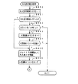
初期化処理では、CPU56は、まず、RAMクリア処理を行う(ステップS10)。なお、RAMクリア処理によって、所定のデータ(例えば、普通図柄当り判定用乱数を生成するためのカウンタのカウント値のデータ)は0に初期化されるが、任意の値またはあらかじめ決められている値に初期化するようにしてもよい。また、RAM55の全領域を初期化せず、所定のデータ(例えば、普通図柄当り判定用乱数を生成するためのカウンタのカウント値のデータ)をそのままにしてもよい。また、ROM54に格納されている初期化時設定テーブルの先頭アドレスをポインタに設定し(ステップS11)、初期化時設定テーブルの内容を順次作業領域に設定する(ステップS12)。
In the initialization process, the
ステップS11およびS12の処理によって、例えば、普通図柄当り判定用乱数カウンタ、特別図柄バッファ、総賞球数格納バッファ、特別図柄プロセスフラグなど制御状態に応じて選択的に処理を行うためのフラグに初期値が設定される。 By the processing of steps S11 and S12, for example, a normal symbol per-determination random number counter, a special symbol buffer, a total winning ball number storage buffer, a special symbol process flag, and other flags for selectively performing processing according to the control state are initialized. Value is set.
また、CPU56は、サブ基板(主基板31以外のマイクロコンピュータが搭載された基板。)を初期化するための初期化指定コマンド(遊技制御用マイクロコンピュータ560が初期化処理を実行したことを示すコマンドでもある。)をサブ基板に送信する(ステップS13)。例えば、演出制御用マイクロコンピュータ100は、初期化指定コマンドを受信すると、演出表示装置9において、遊技機の制御の初期化がなされたことを報知するための画面表示、すなわち初期化報知を行う。
Further, the
また、CPU56は、乱数回路503を初期設定する乱数回路設定処理を実行する(ステップS14)。CPU56は、例えば、乱数回路設定プログラムに従って処理を実行することによって、乱数回路503にランダムRの値を更新させるための設定を行う。
Further, the
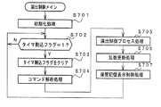
そして、ステップS15において、CPU56は、所定時間(例えば2ms)毎に定期的にタイマ割込がかかるように遊技制御用マイクロコンピュータ560に内蔵されているCTCのレジスタの設定を行う。すなわち、初期値として例えば2msに相当する値が所定のレジスタ(時間定数レジスタ)に設定される。この実施の形態では、2ms毎に定期的にタイマ割込がかかるとする。
In step S15, the
初期化処理の実行(ステップS10〜S15)が完了すると、CPU56は、メイン処理で、表示用乱数更新処理(ステップS17)および初期値用乱数更新処理(ステップS18)を繰り返し実行する。表示用乱数更新処理および初期値用乱数更新処理を実行するときには割込禁止状態に設定し(ステップS16)、表示用乱数更新処理および初期値用乱数更新処理の実行が終了すると割込許可状態に設定する(ステップS19)。この実施の形態では、表示用乱数とは、大当りとしない場合の特別図柄の停止図柄を決定するための乱数や大当りとしない場合にリーチとするか否かを決定するための乱数であり、表示用乱数更新処理とは、表示用乱数を発生するためのカウンタのカウント値を更新する処理である。また、初期値用乱数更新処理とは、初期値用乱数を発生するためのカウンタのカウント値を更新する処理である。この実施の形態では、初期値用乱数とは、普通図柄に関して当りとするか否か決定するための乱数を発生するためのカウンタ(普通図柄当り判定用乱数発生カウンタ)のカウント値の初期値を決定するための乱数である。後述する遊技の進行を制御する遊技制御処理(遊技制御用マイクロコンピュータ560が、遊技機に設けられている演出表示装置、可変入賞球装置、球払出装置等の遊技用の装置を、自身で制御する処理、または他のマイクロコンピュータに制御させるために指令信号を送信する処理、遊技装置制御処理ともいう)において、普通図柄当り判定用乱数のカウント値が1周(普通図柄当り判定用乱数の取りうる値の最小値から最大値までの間の数値の個数分歩進したこと)すると、そのカウンタに初期値が設定される。
When the execution of the initialization process (steps S10 to S15) is completed, the
なお、この実施の形態では、リーチ演出は、演出表示装置9において可変表示される演出図柄(飾り図柄)を用いて実行される。また、特別図柄の表示結果を大当り図柄にする場合には、リーチ演出は常に実行される。特別図柄の表示結果を大当り図柄にしない場合には、遊技制御用マイクロコンピュータ560は、乱数を用いた抽選によって、リーチ演出を実行するか否か決定する。ただし、実際にリーチ演出の制御を実行するのは、演出制御用マイクロコンピュータ100である。
In this embodiment, the reach effect is executed using an effect symbol (decorative symbol) variably displayed on the
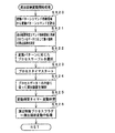
タイマ割込が発生すると、CPU56は、図5に示すステップS20〜S34のタイマ割込処理を実行する。タイマ割込処理において、まず、電源断信号が出力されたか否か(オン状態になったか否か)を検出する電源断検出処理を実行する(ステップS20)。電源断信号は、例えば電源基板に搭載されている電源監視回路が、遊技機に供給される電源の電圧の低下を検出した場合に出力する。そして、電源断検出処理において、CPU56は、電源断信号が出力されたことを検出したら、必要なデータをバックアップRAM領域に保存するための電力供給停止時処理を実行する。次いで、入力ドライバ回路58を介して、ゲートスイッチ32a、第1始動口スイッチ13a、第2始動口スイッチ14aおよびカウントスイッチ23の検出信号を入力し、それらの状態判定を行う(スイッチ処理:ステップS21)。
When the timer interrupt occurs, the
次に、CPU56は、第1特別図柄表示器8a、第2特別図柄表示器8b、普通図柄表示器10、第1特別図柄保留記憶表示器18a、第2特別図柄保留記憶表示器18b、普通図柄保留記憶表示器41の表示制御を行う表示制御処理を実行する(ステップS22)。第1特別図柄表示器8a、第2特別図柄表示器8bおよび普通図柄表示器10については、ステップS32,S33で設定される出力バッファの内容に応じて各表示器に対して駆動信号を出力する制御を実行する。
Next, the
また、遊技制御に用いられる普通当り図柄決定用の乱数等の各判定用乱数を生成するための各カウンタのカウント値を更新する処理を行う(判定用乱数更新処理:ステップS23)。CPU56は、さらに、初期値用乱数および表示用乱数を生成するためのカウンタのカウント値を更新する処理を行う(初期値用乱数更新処理,表示用乱数更新処理:ステップS24,S25)。
In addition, a process of updating the count value of each counter for generating each random number for determination such as a random number for determining a normal winning symbol used for game control is performed (determination random number update process: step S23). The
さらに、CPU56は、特別図柄プロセス処理を行う(ステップS26)。特別図柄プロセス処理では、第1特別図柄表示器8a、第2特別図柄表示器8bおよび大入賞口を所定の順序で制御するための特別図柄プロセスフラグに従って該当する処理を実行する。CPU56は、特別図柄プロセスフラグの値を、遊技状態に応じて更新する。
Further, the
次いで、普通図柄プロセス処理を行う(ステップS27)。普通図柄プロセス処理では、CPU56は、普通図柄表示器10の表示状態を所定の順序で制御するための普通図柄プロセスフラグに従って該当する処理を実行する。CPU56は、普通図柄プロセスフラグの値を、遊技状態に応じて更新する。
Next, normal symbol process processing is performed (step S27). In the normal symbol process, the
また、CPU56は、演出制御用マイクロコンピュータ100に演出制御コマンドを送出する処理を行う(演出制御コマンド制御処理:ステップS28)。
Further, the
さらに、CPU56は、例えばホール管理用コンピュータに供給される大当り情報、始動情報、確率変動情報などのデータを出力する情報出力処理を行う(ステップS29)。
Further, the
また、CPU56は、第1始動口スイッチ13a、第2始動口スイッチ14aおよびカウントスイッチ23の検出信号にもとづく賞球個数の設定などを行う賞球処理を実行する(ステップS30)。具体的には、第1始動口スイッチ13a、第2始動口スイッチ14aおよびカウントスイッチ23のいずれかがオンしたことにもとづく入賞検出に応じて、払出制御基板37に搭載されている払出制御用マイクロコンピュータに賞球個数を示す払出制御コマンド(賞球個数信号)を出力する。払出制御用マイクロコンピュータは、賞球個数を示す払出制御コマンドに応じて球払出装置97を駆動する。
Further, the
この実施の形態では、出力ポートの出力状態に対応したRAM領域(出力ポートバッファ)が設けられているのであるが、CPU56は、出力ポートの出力状態に対応したRAM領域におけるソレノイドのオン/オフに関する内容を出力ポートに出力する(ステップS31:出力処理)。
In this embodiment, a RAM area (output port buffer) corresponding to the output state of the output port is provided. However, the
また、CPU56は、特別図柄プロセスフラグの値に応じて特別図柄の演出表示を行うための特別図柄表示制御データを特別図柄表示制御データ設定用の出力バッファに設定する特別図柄表示制御処理を行う(ステップS32)。CPU56は、例えば、特別図柄プロセス処理でセットされる開始フラグがセットされると終了フラグがセットされるまで、変動速度が1コマ/0.2秒であれば、0.2秒が経過する毎に、出力バッファに設定される表示制御データの値を+1する。また、CPU56は、出力バッファに設定された表示制御データに応じて、ステップS22において駆動信号を出力することによって、第1特別図柄表示器8aおよび第2特別図柄表示器8bにおける第1特別図柄および第2特別図柄の可変表示を実行する。
Further, the
さらに、CPU56は、普通図柄プロセスフラグの値に応じて普通図柄の演出表示を行うための普通図柄表示制御データを普通図柄表示制御データ設定用の出力バッファに設定する普通図柄表示制御処理を行う(ステップS33)。CPU56は、例えば、普通図柄の変動に関する開始フラグがセットされると終了フラグがセットされるまで、普通図柄の変動速度が0.2秒ごとに表示状態(「○」および「×」)を切り替えるような速度であれば、0.2秒が経過する毎に、出力バッファに設定される表示制御データの値(例えば、「○」を示す1と「×」を示す0)を切り替える。また、CPU56は、出力バッファに設定された表示制御データに応じて、ステップS22において駆動信号を出力することによって、普通図柄表示器10における普通図柄の演出表示を実行する。
Further, the
その後、割込許可状態に設定し(ステップS34)、処理を終了する。 Thereafter, the interrupt permission state is set (step S34), and the process is terminated.
以上の制御によって、この実施の形態では、遊技制御処理は2ms毎に起動されることになる。なお、遊技制御処理は、タイマ割込処理におけるステップS21〜S33(ステップS29を除く。)の処理に相当する。また、この実施の形態では、タイマ割込処理で遊技制御処理が実行されているが、タイマ割込処理では例えば割込が発生したことを示すフラグのセットのみがなされ、遊技制御処理はメイン処理において実行されるようにしてもよい。 With the above control, in this embodiment, the game control process is started every 2 ms. The game control process corresponds to the processes of steps S21 to S33 (excluding step S29) in the timer interrupt process. In this embodiment, the game control process is executed by the timer interrupt process. However, in the timer interrupt process, for example, only a flag indicating that an interrupt has occurred is set, and the game control process is performed by the main process. May be executed.
第1特別図柄表示器8aまたは第2特別図柄表示器8bおよび演出表示装置9にはずれ図柄が停止表示される場合には、演出図柄の可変表示が開始されてから、演出図柄の可変表示状態がリーチ状態にならずに、リーチにならない所定の演出図柄の組み合わせが停止表示されることがある。このような演出図柄の可変表示態様を、可変表示結果がはずれ図柄になる場合における「非リーチ」(「通常はずれ」ともいう)の可変表示態様という。
When the shifted symbol is stopped and displayed on the first
第1特別図柄表示器8aまたは第2特別図柄表示器8bおよび演出表示装置9にはずれ図柄が停止表示される場合には、演出図柄の可変表示が開始されてから、演出図柄の可変表示状態がリーチ状態となったことに応じて、リーチ演出が実行された後に、または、リーチ演出が実行されずに、リーチにならない所定の演出図柄の組み合わせが停止表示されることがある。このような演出図柄の可変表示結果を、可変表示結果が「はずれ」となる場合における「リーチ」(「リーチはずれ」ともいう)の可変表示態様という。
When the shifted symbol is stopped and displayed on the first
この実施の形態では、第1特別図柄表示器8aまたは第2特別図柄表示器8bに大当り図柄が停止表示される場合には、演出図柄の可変表示状態がリーチ状態になった後にリーチ演出が実行され、またはリーチ演出が実行されずに、演出表示装置9における「左」、「中」、「右」の各図柄表示エリア9L、9C、9Rに、演出図柄が揃って停止表示される。
In this embodiment, when the big win symbol is stopped and displayed on the first
第1特別図柄表示器8aまたは第2特別図柄表示器8bに小当りである「5」が停止表示される場合には、演出表示装置9において、演出図柄の可変表示態様が「突然確変大当り」である場合と同様に演出図柄の可変表示が行われた後、所定の小当り図柄(突然確変大当り図柄と同じ図柄。例えば「135」)が停止表示されることがある。第1特別図柄表示器8aまたは第2特別図柄表示器8bに小当り図柄である「5」が停止表示されることに対応する演出表示装置9における表示演出を「小当り」の可変表示態様という。
When “5”, which is a small hit, is stopped and displayed on the first
ここで、小当りとは、大当りと比較して大入賞口の開放回数が少ない回数(この実施の形態では0.1秒間の開放を2回)まで許容される当りである。なお、小当り遊技が終了した場合、遊技状態は変化しない。すなわち、確変状態から通常状態に移行したり通常状態から確変状態に移行したりすることはない。また、突然確変大当りとは、大当り遊技状態において大入賞口の開放回数が少ない回数(この実施の形態では0.1秒間の開放を2回)まで許容されるが大入賞口の開放時間が極めて短い大当りであり、かつ、大当り遊技後の遊技状態を確変状態に移行させるような大当りである(すなわち、そのようにすることにより、遊技者に対して突然に確変状態となったかのように見せるものである)。つまり、この実施の形態では、突然確変大当りと小当りとは、大入賞口の開放パターンが同じである。そのように制御することによって、大入賞口の0.1秒間の開放が2回行われると、突然確変大当りであるか小当りであるかまでは認識できないので、遊技者に対して高確率状態(確変状態)を期待させることができ、遊技の興趣を向上させることができる。 Here, the small win is a hit that is allowed up to a small number of times that the big winning opening is opened compared to the big win (in this embodiment, the opening for 0.1 second is twice). When the small hit game ends, the game state does not change. That is, there is no transition from the probability variation state to the normal state or from the normal state to the certain variation state. In addition, the sudden probability change big hit is allowed up to a small number of times of opening of the big winning opening in the big hit gaming state (in this embodiment, opening for 0.1 second is twice), but the opening time of the big winning opening is extremely large. It is a big jackpot that is a short jackpot and the game state after the big jackpot game is shifted to a probabilistic state (that is, by doing so, it appears to the player as if it suddenly became a probable state) Is). That is, in this embodiment, the sudden winning odds and the small wins have the same opening pattern of the big prize opening. By controlling in such a way, if the winning opening is opened twice for 0.1 seconds, it is impossible to recognize whether it is suddenly a big hit or a small hit, so a high probability state for the player (Probable change state) can be expected, and the interest of the game can be improved.
図6は、可変表示結果がはずれ図柄になる場合における演出図柄の可変表示態様が「非リーチ」である場合と「リーチ」である場合のそれぞれに対応してあらかじめ用意された演出図柄の変動パターンを示す説明図である。図6に示すように、この実施の形態では、演出図柄の可変表示態様が「非リーチ」である場合に対応した変動パターンとして、非リーチPA1−1〜非リーチPA1−5、非リーチPB1−1、非リーチPB1−2、非リーチPC1−1〜非リーチPC1−3の変動パターンが用意されている。また、演出図柄の可変表示態様が「リーチ」である場合に対応した変動パターンとして、ノーマルPA2−1〜ノーマルPA2−4、スーパーPA3−1〜スーパーPA3−6、スーパーPB3−1〜スーパーPB3−3、スーパーPC3−1、スーパーPC3−2の変動パターンが用意されている。なお、図6に示すように、リーチしない場合に使用され擬似連の演出を伴う非リーチPA1−5の変動パターンについては、再変動が2回行われる。 FIG. 6 shows the variation patterns of the effect symbols prepared in advance corresponding to the cases where the variable display mode of the effect symbol is “non-reach” and “reach” when the variable display result is an off-symbol. It is explanatory drawing which shows. As shown in FIG. 6, in this embodiment, non-reach PA1-1 to non-reach PA1-5, non-reach PB1- 1, fluctuation patterns of non-reach PB1-2, non-reach PC1-1 to non-reach PC1-3 are prepared. In addition, normal PA2-1 to normal PA2-4, super PA3-1 to super PA3-6, super PB3-1 to super PB3- 3, fluctuation patterns of super PC 3-1 and super PC 3-2 are prepared. As shown in FIG. 6, the re-variation is performed twice for the non-reach PA 1-5 variation pattern that is used when the reach is not performed and has a pseudo-continuous effect.
図7は、可変表示結果が大当り図柄または小当り図柄になる場合に対応してあらかじめ用意された演出図柄の変動パターンを例示する説明図である。図7に示すように、この実施の形態では、特別図柄の可変表示結果が大当り図柄または小当り図柄になる場合に対応した変動パターンとして、ノーマルPA2−5〜ノーマルPA2−8、スーパーPA4−1〜スーパーPA4−6、スーパーPB4−1〜スーパーPB4−3、スーパーPD1−1およびスーパーPD1−2、特殊PG1−1〜特殊PG1−3、特殊PG2−1〜特殊PG2−2の変動パターンが用意されている。なお、図7において、特殊PG1−1〜特殊PG1−3、特殊PG2−1〜特殊PG2−2の変動パターンは、突然確変大当りまたは小当りとなる場合に使用される変動パターンである。また、図7に示すように、突然確変大当りまたは小当りでない場合に使用され擬似連の演出を伴う変動パターンについては、再変動が3回行われる。突然確変大当りまたは小当りの場合に使用され擬似連の演出を伴う特殊PG1−3の変動パターンについては、再変動が2回行われる。 FIG. 7 is an explanatory diagram exemplifying a variation pattern of the effect symbol prepared in advance in response to the case where the variable display result is a big hit symbol or a small hit symbol. As shown in FIG. 7, in this embodiment, normal PA2-5 to normal PA2-8 and super PA4-1 are used as the variation patterns corresponding to the case where the variable symbol display result of the special symbol is a big hit symbol or a small hit symbol. -Fluctuation patterns of Super PA4-6, Super PB4-1 to Super PB4-3, Super PD1-1 and Super PD1-2, Special PG1-1 to Special PG1-3, Special PG2-1 to Special PG2-2 are available Has been. In FIG. 7, the variation patterns of special PG1-1 to special PG1-3 and special PG2-1 to special PG2-2 are variation patterns used when suddenly sudden change is a big hit or a small hit. Further, as shown in FIG. 7, re-variation is performed three times for the variation pattern that is used when sudden sudden change is not big hit or small hit and has a pseudo-continuous effect. For the variation pattern of the special PG 1-3 that is used in the case of sudden big hit or small hit suddenly and has a pseudo-ream effect, re-variation is performed twice.
図8は、各乱数を示す説明図である。各乱数は、以下のように使用される。
(2−1)ランダム2−1(MR2−1):大当りの種類(後述する通常大当り、確変大当りA、確変大当りB、突然確変大当り)を決定する(大当り種別判定用)
(2−2)ランダム2−2(MR2−2): リーチとするか否か決定する(リーチ判定用)
(3)ランダム3(MR3):変動パターンの種類(種別)を決定する(変動パターン種別判定用)
(4)ランダム4(MR4):変動パターン(変動時間)を決定する(変動パターン判定用)
(5)ランダム5(MR5):普通図柄にもとづく当りを発生させるか否か決定する(普通図柄当り判定用)
(6)ランダム6(MR6):ランダム5の初期値を決定する(ランダム5初期値決定用)
FIG. 8 is an explanatory diagram showing each random number. Each random number is used as follows.
(2-1) Random 2-1 (MR2-1): Determines the type of jackpot (normal jackpot, probability variation jackpot A, probability variation jackpot B, sudden probability variation jackpot described later) (for jackpot type determination)
(2-2) Random 2-2 (MR2-2): Determines whether or not to reach (for reach determination)
(3) Random 3 (MR3): The type (type) of the variation pattern is determined (for variation pattern type determination)
(4) Random 4 (MR4): A variation pattern (variation time) is determined (for variation pattern determination)
(5) Random 5 (MR5): Determines whether or not to generate a hit based on the normal symbol (for normal symbol hit determination)
(6) Random 6 (MR6): Determine the initial value of random 5 (for determining the initial value of random 5)
図5に示された遊技制御処理におけるステップS23では、遊技制御用マイクロコンピュータ560は、(2−1)の大当り種別判定用乱数、および(5)の普通図柄当り判定用乱数を生成するためのカウンタのカウントアップ(1加算)を行う。すなわち、それらが判定用乱数であり、それら以外の乱数が表示用乱数(ランダム2−2、ランダム3、ランダム4)または初期値用乱数(ランダム6)である。なお、遊技効果を高めるために、上記の乱数以外の乱数も用いてもよい。また、この実施の形態では、大当り判定用乱数として、遊技制御用マイクロコンピュータ560に内蔵されたハードウェア(遊技制御用マイクロコンピュータ560の外部のハードウェアでもよい。)が生成する乱数を用いる。
In step S23 in the game control process shown in FIG. 5, the
図9(A)は、大当り判定テーブルを示す説明図である。大当り判定テーブルとは、ROM54に記憶されているデータの集まりであって、ランダムRと比較される大当り判定値が設定されているテーブルである。大当り判定テーブルには、通常状態(確変状態でない遊技状態)において用いられる通常時大当り判定テーブルと、確変状態において用いられる確変時大当り判定テーブルとがある。通常時大当り判定テーブルには、図9(A)の左欄に記載されている各数値が設定され、確変時大当り判定テーブルには、図9(A)の右欄に記載されている各数値が設定されている。図9(A)に記載されている数値が大当り判定値である。
FIG. 9A is an explanatory diagram showing a jackpot determination table. The jackpot determination table is a collection of data stored in the
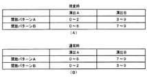
図9(B)は、小当り判定テーブルを示す説明図である。小当り判定テーブルとは、ROM54に記憶されているデータの集まりであって、ランダムRと比較される小当り判定値が設定されているテーブルである。小当り判定テーブルには、第1特別図柄表示器8aにおいて小当り図柄が停止表示される場合に用いられる第1特別図柄小当り判定テーブルと、第2特別図柄表示器8bにおいて小当り図柄が停止表示される場合に用いられる第2特別図柄小当り判定テーブルとがある。第1特別図柄小当り判定テーブルには、図9(B)の左欄に記載されている各数値が設定され、第2特別図柄小当り判定テーブルには、図9(B)の右欄に記載されている各数値が設定されている。また、図9(B)に記載されている数値が小当り判定値である。図9(B)に示すように、本実施の形態では、第2特別図柄小当り判定テーブルよりも、第1特別図柄小当り判定テーブルに多くの小当り判定値が設定されており、第1特別図柄表示器8aには、第2特別図柄表示器8bよりも小当り図柄が表示される割合が高い。具体的には、第1特別図柄表示器8aには1/150の確率で小当り図柄が表示されるのに対し、第2特別図柄表示器8bには1/300の確率で小当り図柄が表示される
FIG. 9B is an explanatory diagram showing a small hit determination table. The small hit determination table is a collection of data stored in the
そして、小当り判定値は、開放パターンAまたは開放パターンBのいずれかに対応づけられている。図9(B)に示す例では、第1特別図柄小当り判定テーブルにおける54000〜54217の値に開放パターンAが対応づけられ、54218〜54434の値に開放パターンBが対応づけられている。また、第2特別図柄小当り判定テーブルにおける54000〜54108の値に開放パターンAが対応づけられ、54109〜54217の値に開放パターンBが対応づけられている。よって、小当りと決定されるときには、開放パターンAまたは開放パターンBのいずれかに決定されることとなる。開放パターンAおよび開放パターンBについては後述する。
The small hit determination value is associated with either the opening pattern A or the opening pattern B. In the example shown in FIG. 9B, the opening pattern A is associated with the
CPU56は、所定の時期に、乱数回路503のカウント値を抽出して抽出値を大当り判定用乱数(ランダムR)の値とするのであるが、大当り判定用乱数値が図9(A)に示すいずれかの大当り判定値に一致すると、特別図柄に関して大当り(15R通常大当り、15R確変大当り、突然確変大当り)にすることに決定する。また、大当り判定用乱数値が図9(B)に示すいずれかの小当り判定値に一致すると、特別図柄に関して小当りにすることに決定する。なお、図9(A)に示す「確率」は、大当りになる確率(割合)を示す。また、図9(B)に示す「確率」は、小当りになる確率(割合)を示す。また、大当りにするか否か決定するということは、大当り遊技状態に移行させるか否か決定するということであるが、第1特別図柄表示器8aまたは第2特別図柄表示器8bにおける停止図柄を大当り図柄にするか否か決定するということでもある。また、小当りにするか否か決定するということは、小当り遊技状態に移行させるか否か決定するということであるが、第1特別図柄表示器8aまたは第2特別図柄表示器8bにおける停止図柄を小当り図柄にするか否か決定するということでもある。
The
図9(C),(D)は、ROM54に記憶されている大当り種別判定テーブル131a,131bを示す説明図である。このうち、図9(C)は、遊技球が第1始動入賞口13に入賞したことにもとづく保留記憶を用いて(すなわち、第1特別図柄の変動表示が行われるとき)大当り種別を決定する場合の大当り種別判定テーブル(第1特別図柄用)131aである。また、図9(D)は、遊技球が第2始動入賞口14に入賞したことにもとづく保留記憶を用いて(すなわち、第2特別図柄の変動表示が行われるとき)大当り種別を決定する場合の大当り種別判定テーブル(第2特別図柄用)131bである。
FIGS. 9C and 9D are explanatory diagrams showing the jackpot type determination tables 131a and 131b stored in the
大当り種別判定テーブル131a,131bは、可変表示結果を大当り図柄にする旨の判定がなされたときに、大当り種別判定用の乱数(ランダム2−1)にもとづいて、大当りの種別を「15R通常大当り」、「15R確変大当り」、「突然確変大当り」のうちのいずれかに決定するために参照されるテーブルである。なお、この実施の形態では、図9(C),(D)に示すように、大当り種別判定テーブル131aには「15R通常大当り」、「15R確変大当り」および「突然確変大当り」の全てに対して判定値が割り当てられているが、大当り種別判定テーブル131bには「15R通常大当り」と「15R確変大当り」にのみ判定値が割り当てられていてもよい。つまり、図9(D)は、遊技球が第2始動入賞口14に入賞したことにもとづく保留記憶を用いて(すなわち、第2特別図柄の変動表示が行われるとき)大当り種別を決定する場合に、「突然確変大当り」に決定しないように構成されていてもよい。 The jackpot type determination table 131a, 131b determines that the jackpot type is “15R normal jackpot” based on the random number (random 2-1) for determining the jackpot type when it is determined that the variable display result is a jackpot symbol. ”,“ 15R probability variation big hit ”, and“ sudden probability variation big hit ”. In this embodiment, as shown in FIGS. 9C and 9D, the big hit type determination table 131a includes all of “15R normal big hit”, “15R probability big hit” and “sudden probability big hit”. The determination value may be assigned to the big hit type determination table 131b only for “15R normal big hit” and “15R probability big hit”. That is, FIG. 9 (D) shows a case where the jackpot type is determined using the holding memory based on the game ball having won the second start winning opening 14 (that is, when the second special symbol is displayed in a variable manner). In addition, it may be configured not to determine “suddenly probable big hit”.
ここで、「15R確変大当り」とは、15ラウンドの大当り遊技状態に制御し、その大当り遊技状態の終了後に確変状態に移行させる大当りである。また、「15R通常大当り」とは、15ラウンドの大当り遊技状態に制御し、その大当り遊技状態の終了後に確変状態に移行されない(この実施の形態では、時短状態にのみ移行される)大当りである。また、「突然確変大当り」とは、2ラウンドの大当り遊技状態に制御し、その大当り遊技状態の終了後に確変状態に移行させる大当りである。 Here, the “15R probability variation big hit” is a big hit that is controlled to the 15-round big hit gaming state and shifts to the probability changed state after the big hit gaming state ends. In addition, the “15R normal big hit” is a big hit that is controlled to the 15-round big hit gaming state and is not shifted to the probability change state after the big hit gaming state is finished (in this embodiment, only the short time state is transferred). . The “suddenly probable big hit” is a big hit that is controlled to a two-round big hit gaming state and is shifted to a probable change state after the big hit gaming state ends.
大当り種別判定テーブル131a,131bには、ランダム2−1の値と比較される数値であって、「15R通常大当り」、「15R確変大当り」、「突然確変大当り」のそれぞれに対応した判定値(大当り種別判定値)が設定されている。CPU56は、ランダム2−1の値が大当り種別判定値のいずれかに一致した場合に、大当りの種別を、一致した大当り種別判定値に対応する種別に決定する。
The big hit type determination tables 131a and 131b are numerical values to be compared with random 2-1 values, which are judgment values corresponding to “15R normal big hit”, “15R probability big hit”, and “sudden probability big hit” ( Big hit type judgment value) is set. When the random value 2-1 matches any of the jackpot type determination values, the
また、大当り種別判定テーブル131a,131bには、ランダム2−1の値と比較される数値であって、「突然確変大当り」のそれぞれに対応した判定値(大当り種別判定値)は、さらに、開放パターンAまたは開放パターンBのいずれかに対応づけられている。図9(C)に示す例では、大当り種別判定テーブル131aにおける30〜34の値に開放パターンAが対応づけられ、35〜39の値に開放パターンBが対応づけられている。また、大当り種別判定テーブル131bにおける36〜37の値に開放パターンAが対応づけられ、38〜39の値に開放パターンBが対応づけられている。よって、突然確変大当りと決定されるときには、開放パターンAまたは開放パターンBのいずれかに決定されることとなる。開放パターンAおよび開放パターンBについては後述する。
In addition, in the big hit type determination tables 131a and 131b, numerical values that are compared with the values of the random 2-1, and the determination values (big hit type determination values) corresponding to each of the “sudden probability variation big hits” are further released. Corresponding to either pattern A or open pattern B. In the example shown in FIG. 9C, the release pattern A is associated with the
図10は、図9(C),(D)に示す大当り種別判定テーブル131a,131bを用いて決定される大当り種別の決定割合を示す説明図である。このうち、図10(A)は、遊技球が第1始動入賞口13に入賞したことにもとづく保留記憶を用いて(すなわち、第1特別図柄の変動表示が行われるとき)決定される大当り種別の割合を示している。また、図10(B)は、遊技球が第2始動入賞口14に入賞したことにもとづく保留記憶を用いて(すなわち、第2特別図柄の変動表示が行われるとき)決定される大当り種別の割合を示している。 FIG. 10 is an explanatory diagram showing the determination ratio of the jackpot type determined using the jackpot type determination tables 131a and 131b shown in FIGS. Of these, FIG. 10 (A) shows the jackpot type determined using the holding memory based on the fact that the game ball has won the first start winning opening 13 (that is, when the variable display of the first special symbol is performed). Shows the percentage. Further, FIG. 10B shows a jackpot type determined by using a holding memory based on the game ball having won the second start winning opening 14 (that is, when the variation display of the second special symbol is performed). The ratio is shown.
図10(A)に示すように、この実施の形態では、第1特別図柄の変動表示が実行され大当りとすることに決定される場合には、50パーセントの割合で「15R確変大当り」に決定され、「15R通常大当り」および「突然確変大当り」がそれぞれ均等に25パーセントずつの割合で決定される。 As shown in FIG. 10A, in this embodiment, when the first special symbol variation display is executed and it is determined to be a big hit, it is determined to be “15R probability variable big hit” at a rate of 50%. Then, “15R normal big hit” and “suddenly probable big hit” are determined equally at a rate of 25 percent.
また、図10(B)に示すように、この実施の形態では、第2特別図柄の変動表示が実行され大当りとすることに決定される場合には、65パーセントの割合で「15R確変大当り」とすることに決定され、25パーセントの割合で「15R通常大当り」とすることに決定され、10パーセントの割合で「突然確変大当り」とすることに決定される。従って、この実施の形態では、後述するように、第2特別図柄の変動表示が優先して実行されるのであるから、大当りとなったときに、15R確変大当りが連続して発生しやすい。 Also, as shown in FIG. 10B, in this embodiment, when the variable display of the second special symbol is executed and it is determined to be a big hit, “15R probability change big hit” at a rate of 65%. It is determined to be “15R normal jackpot” at a rate of 25%, and “suddenly promiscuous jackpot” at a rate of 10%. Therefore, in this embodiment, as will be described later, since the fluctuation display of the second special symbol is executed with priority, when the big hit is made, the 15R probability variation big hit is likely to occur continuously.
図11(A)〜(C)は、大当り用変動パターン種別判定テーブル132A〜132Cを示す説明図である。大当り用変動パターン種別判定テーブル132A〜132Cは、可変表示結果を大当り図柄にする旨の判定がなされたときに、大当り種別の判定結果に応じて、変動パターン種別を、変動パターン種別判定用の乱数(ランダム3)にもとづいて複数種類のうちのいずれかに決定するために参照されるテーブルである。 11A to 11C are explanatory diagrams showing the big hit variation pattern type determination tables 132A to 132C. The jackpot variation pattern type determination tables 132A to 132C, when it is determined that the variable display result is a jackpot symbol, the variation pattern type is determined according to the determination result of the jackpot type, and the random number for determining the variation pattern type. It is a table that is referred to in order to determine one of a plurality of types based on (Random 3).
各大当り用変動パターン種別判定テーブル132A〜132Cには、変動パターン種別判定用の乱数(ランダム3)の値と比較される数値(判定値)であって、ノーマルCA3−1、スーパーCA3−2〜スーパーCA3−4、特殊CA4−1、特殊CA4−2の変動パターン種別のいずれかに対応する判定値が設定されている。 Each of the big hit variation pattern type determination tables 132A to 132C includes a numerical value (determination value) to be compared with a random number (random 3) value for variation pattern type determination, and includes normal CA3-1 and super CA3-2-. A determination value corresponding to any one of the variation pattern types of super CA3-4, special CA4-1, and special CA4-2 is set.
例えば、大当り種別が「15R通常大当り」である場合に用いられる図11(A)に示す大当り用変動パターン種別判定テーブル132Aと、大当り種別が「15R確変大当り」である場合に用いられる図11(B)に示す大当り用変動パターン種別判定テーブル132Bとで、ノーマルCA3−1やスーパーCA3−2の変動パターン種別に対する判定値の割り当てが異なっている。また、大当り用変動パターン種別判定テーブル132Aでは、スーパーCA3−3の変動パターン種別に対して判定値が割り当てられ、大当り用変動パターン種別判定テーブル132Bでは、スーパーCA3−3の変動パターン種別に対して判定値が割り当てられていない。また、大当り用変動パターン種別判定テーブル132Aでは、スーパーCA3−4の変動パターン種別に対して判定値が割り当てられず、大当り用変動パターン種別判定テーブル132Bでは、スーパーCA3−4の変動パターン種別に対して判定値が割り当てられている。 For example, the big hit variation pattern type determination table 132A shown in FIG. 11A used when the big hit type is “15R normal big hit”, and the big hit type shown in FIG. The allocation of determination values to the variation pattern types of normal CA3-1 and super CA3-2 is different from the big hit variation pattern type determination table 132B shown in FIG. In the big hit variation pattern type determination table 132A, a determination value is assigned to the variation pattern type of the super CA3-3, and in the big hit variation pattern type determination table 132B, the variation value type of the super CA3-3. The judgment value is not assigned. Further, in the big hit variation pattern type determination table 132A, no determination value is assigned to the variation pattern type of the super CA 3-4, and in the big hit variation pattern type determination table 132B, the variation pattern type of the super CA 3-4 is not assigned. Judgment value is assigned.
このように、大当り種別に応じて選択される大当り用変動パターン種別判定テーブル132A〜132Cを比較すると、大当り種別に応じて各変動パターン種別に対する判定値の割り当てが異なっている。また、大当り種別に応じて異なる変動パターン種別に対して判定値が割り当てられている。よって、大当り種別を複数種類のうちのいずれにするかの決定結果に応じて、異なる変動パターン種別に決定することができ、同一の変動パターン種別に決定される割合を異ならせることができる。 As described above, when the big hit variation pattern type determination tables 132A to 132C selected according to the big hit type are compared, the assignment of the determination value to each fluctuation pattern type is different according to the big hit type. Also, determination values are assigned to different variation pattern types depending on the jackpot type. Therefore, different variation pattern types can be determined according to the determination result of whether the big hit type is a plurality of types, and the ratio determined for the same variation pattern type can be varied.
また、大当り種別が「突然確変大当り」である場合に用いられる大当り用変動パターン種別判定テーブル132Cでは、例えば、特殊CA4−1、特殊CA4−2といった大当り種別が「突然確変大当り」以外である場合には判定値が割り当てられない変動パターン種別に対して、判定値が割り当てられている。よって、可変表示結果が「大当り」となり大当り種別が「突然確変大当り」となることに応じて2ラウンド大当り状態に制御する場合には、15ラウンド大当り状態に制御する場合とは異なる変動パターン種別に決定することができる。 Further, in the big hit variation pattern type judgment table 132C used when the big hit type is “suddenly probable big hit”, for example, when the big hit type such as special CA4-1 and special CA4-2 is other than “suddenly probable big hit” A determination value is assigned to a variation pattern type to which no determination value is assigned. Therefore, when the variable display result is “big hit” and the big hit type is “suddenly probable big hit”, when the control is set to the two round big hit state, the variation pattern type is different from the case of controlling to the 15 round big hit state. Can be determined.
また、図11(D)は、小当り用変動パターン種別判定テーブル132Dを示す説明図である。小当り用変動パターン種別判定テーブル132Dは、可変表示結果を小当り図柄にする旨の判定がなされたときに、変動パターン種別を、変動パターン種別判定用の乱数(ランダム3)にもとづい
て複数種類のうちのいずれかに決定するために参照されるテーブルである。なお、この実施の形態では、図11(D)に示すように、小当りとすることに決定されている場合には、変動パターン種別として特殊CA4−1が決定される場合が示されている。
FIG. 11D is an explanatory diagram showing a small hit variation pattern type determination table 132D. The small hit variation pattern type determination table 132D has a plurality of variation pattern types based on a random number (random 3) for variation pattern type determination when it is determined that the variable display result is a small hit symbol. It is a table that is referred to in order to determine any of the above. In this embodiment, as shown in FIG. 11D, when it is determined to be a small hit, a case where the special CA4-1 is determined as the variation pattern type is shown. .
図12(A)〜(D)は、ROM54に記憶されているリーチ判定テーブル134A,134B,134C,134Dを示す説明図である。リーチ判定テーブル134A,134B,134C,134Dは、可変表示結果を「はずれ」にする旨の判定がなされたときに、演出図柄の可変表示状態をリーチ状態にするか否かを、リーチ判定用の乱数(ランダム2−2)にもとづいて判定するために参照されるテーブルである。各リーチ判定テーブル134A〜134Dは、図12(E)に示すようなテーブル選択規則に従って選択される。すなわち、遊技状態が通常状態、確変状態および時短状態のうちのいずれであるか、および時短状態である場合には第1特別図柄の変動表示が実行されるのか、または第2特別図柄の変動表示が実行されるのかに応じて選択される。
12A to 12D are explanatory diagrams showing reach determination tables 134A, 134B, 134C, and 134D stored in the
このうち、図12(A)は、遊技状態が通常状態である場合に、リーチ状態にするか否かを決定する場合のリーチ判定テーブル134Aである。図12(A)に示すリーチ判定テーブル134Aの設定では、保留記憶数が「0」である場合に対応して、「1」〜「204」の範囲の値が非リーチHA1−1に割り当てられ、「205」〜「239」の範囲の値がリーチHA2−1に割り当てられている。保留記憶数が「1」である場合に対応して、非リーチHA1−1に割り当てられる判定値の個数よりも多い「1」〜「217」の範囲の値が、非リーチHA1−2に割り当てられている。保留記憶数が「2」である場合に対応して非リーチHA1−1や非リーチHA1−2に割り当てられる判定値の個数よりも多い「1」〜「220」の範囲の値が、非リーチHA1−3に割り当てられている。保留記憶数が「3」である場合や「4」である場合に対応して、非リーチHA1−1〜非リーチHA1−3のそれぞれに割り当てられる判定値の個数よりも多い「1」〜「230」の範囲の判定値が、非リーチHA1−4に割り当てられている。保留記憶数が「5」〜「8」である場合に対応して、非リーチHA1−1〜非リーチHA1−4のそれぞれに割り当てられる判定値の個数よりも多い「1」〜「235」の範囲の判定値が、非リーチHA1−5に割り当てられている。このような設定によって、保留記憶数が所定数(例えば、「3」)以上であるときには、所定数未満であるときに比べて、演出図柄の可変表示状態をリーチ状態にする旨の判定がなされる割合が低くなる。そのように構成された場合には、保留記憶数が多い状態においてリーチ発生確率を低くすることによって、遊技機の稼働率を向上させることができる。また、「非リーチ」に対応した変動パターンにおける平均的な特別図柄の変動時間が「リーチ」に対応した変動パターンにおける平均的な特別図柄の変動時間に比べて短くなるように設定されていれば、保留記憶数が所定数以上であるときには、所定数未満であるときに比べて、平均的な特別図柄の変動時間を短縮することができる。そのように構成された場合には、保留記憶数が早めに減少することになって、遊技機の稼働率をより向上させることができる。 Among these, FIG. 12A shows a reach determination table 134A for determining whether or not to reach the reach state when the gaming state is the normal state. In the setting of the reach determination table 134A shown in FIG. 12A, a value in the range of “1” to “204” is assigned to the non-reach HA 1-1 corresponding to the case where the number of reserved storage is “0”. , “205” to “239” are assigned to the reach HA 2-1. Corresponding to the case where the number of reserved memories is “1”, a value in the range of “1” to “217” that is larger than the number of determination values assigned to the non-reach HA 1-1 is assigned to the non-reach HA 1-2. It has been. A value in the range of “1” to “220”, which is larger than the number of determination values assigned to the non-reach HA 1-1 and the non-reach HA 1-2 corresponding to the case where the number of reserved memories is “2”, is non-reach. Assigned to HA1-3. Corresponding to the case where the number of reserved memories is “3” or “4”, “1” to “1”, which are larger than the number of determination values assigned to each of the non-reach HA 1-1 to non-reach HA 1-3. 230 ”is assigned to non-reach HA1-4. Corresponding to the case where the number of reserved memories is “5” to “8”, “1” to “235”, which are larger than the number of determination values assigned to each of the non-reach HA 1-1 to non-reach HA 1-4. A range determination value is assigned to non-reach HA 1-5. With such a setting, when the number of reserved memories is equal to or greater than a predetermined number (for example, “3”), it is determined that the variable display state of the effect symbol is set to the reach state as compared to when the number is less than the predetermined number. The ratio is lower. In such a configuration, the operating rate of the gaming machine can be improved by lowering the reach occurrence probability in a state where the number of reserved memories is large. If the average special symbol variation time in the variation pattern corresponding to “non-reach” is set to be shorter than the average special symbol variation time in the variation pattern corresponding to “reach”. When the number of reserved memories is greater than or equal to the predetermined number, the average special symbol variation time can be shortened compared to when the number is less than the predetermined number. In such a configuration, the number of reserved memories decreases early, and the operating rate of the gaming machine can be further improved.
また、図12(B)は、遊技状態が確変状態である場合にリーチ状態にするか否かを決定する場合のリーチ判定テーブル134Bである。リーチ判定テーブル134Cは、リーチ判定用の乱数(ランダム2−2)の値と比較される数値(判定値)であって、非リーチHB1−1,非リーチHB1−2といったリーチ状態にしない旨の判定結果や、リーチHB2−1といったリーチ状態にする旨の判定結果のいずれかに対応する判定値を含む。リーチ判定テーブル134Bは、合算保留記憶数に応じてリーチ判定用の乱数(ランダム2−2)の値と比較される数値(判定値)であって、非リーチHB1−1,非リーチHB1−2といったリーチ状態にしない旨の判定結果や、リーチHB2−1といったリーチ状態にする旨の判定結果のいずれかに対応する判定値を含む。 FIG. 12B is a reach determination table 134B for determining whether or not to reach the reach state when the gaming state is a probability change state. The reach determination table 134C is a numerical value (determination value) that is compared with the value of the random number for reach determination (random 2-2), and indicates that the reach state such as non-reach HB1-1 and non-reach HB1-2 is not set. It includes a determination value corresponding to either the determination result or the determination result indicating the reach state such as reach HB2-1. The reach determination table 134B is a numerical value (determination value) to be compared with the value of the random number for reach determination (random 2-2) according to the total number of pending storage, and is non-reach HB1-1, non-reach HB1-2. The determination value corresponding to either the determination result indicating that the reach state is not set or the determination result indicating the reach state such as reach HB2-1 is included.
また、図12(C)は、遊技状態が時短状態であって、第1特別図柄の変動表示が実行される場合にリーチ状態にするか否かを決定する場合のリーチ判定テーブル134Cである。リーチ判定テーブル134Cは、リーチ判定用の乱数(ランダム2−2)の値と比較される数値(判定値)であって、非リーチHC1−1といったリーチ状態にしない旨の判定結果や、リーチHC2−1といったリーチ状態にする旨の判定結果のいずれかに対応する判定値を含む。リーチ判定テーブル134Cは、リーチ判定用の乱数(ランダム2−2)の値と比較される数値(判定値)であって、非リーチHC1−1といったリーチ状態にしない旨の判定結果や、リーチHC2−1といったリーチ状態にする旨の判定結果のいずれかに対応する判定値を含む。 FIG. 12C is a reach determination table 134C for determining whether or not to reach the reach state when the gaming state is the short-time state and the first special symbol variation display is executed. The reach determination table 134C is a numerical value (determination value) to be compared with the value of the random number for reach determination (random 2-2), and the determination result indicating that the reach state such as non-reach HC1-1 is not set, or reach HC2 It includes a determination value corresponding to one of the determination results indicating the reach state such as -1. The reach determination table 134C is a numerical value (determination value) to be compared with the value of the random number for reach determination (random 2-2), and the determination result indicating that the reach state such as non-reach HC1-1 is not set, or reach HC2 It includes a determination value corresponding to one of the determination results indicating the reach state such as -1.
また、図12(D)は、遊技状態が時短状態であって、第2特別図柄の変動表示が実行される場合にリーチ状態にするか否かを決定する場合のリーチ判定テーブル134Dである。リーチ判定テーブル134Dは、リーチ判定用の乱数(ランダム2−2)の値と比較される数値(判定値)であって、非リーチHC1−2や非リーチHC1−3といったリーチ状態にしない旨の判定結果や、リーチHC2−2といったリーチ状態にする旨の判定結果のいずれかに対応する判定値を含む。リーチ判定テーブル134Dは、合算保留記憶数に応じてリーチ判定用の乱数(ランダム2−2)の値と比較される数値(判定値)であって、非リーチHC1−2や非リーチHC1−3といったリーチ状態にしない旨の判定結果や、リーチHC2−1といったリーチ状態にする旨の判定結果のいずれかに対応する判定値を含む。図12(D)に示す例では、合算保留記憶数が1個以下の場合には、非リーチHC1−2およびリーチHC2−1に判定値が設定されているが、非リーチHC1−3には判定値が設定されていない。また、合算保留記憶数が2個以上の場合には、非リーチHC1−3およびリーチHC2−1に判定値が設定されているが、非リーチHC1−2には判定値が設定されていない。このように、第1特別図柄の変動表示が実行される場合と第2特別図柄の変動表示が実行される場合とで、それぞれリーチ状態にするか否かを決定する場合のリーチ判定テーブルを用意されている場合には、第2特別図柄の変動表示が実行される場合にリーチ発生確率を高く設定し、第2始動口が遊技媒体が入賞し難い第2状態になっているときに相対的に可変表示の実行条件をより多く成立させうる第1特別図柄の変動表示におけるリーチ発生確率を低くすることによって、遊技機の稼働率をより向上させることができる。また、第2入賞口が遊技媒体が入賞し難い第2状態から遊技媒体が入賞しやすい第1状態に変化したときに遊技者は識別情報の可変表示の実行条件が成立しやすくなるという期待感を抱くのであるが、そのときの入賞に応じた識別情報の可変表示においてリーチ態様が生じやすくなるので、遊技者の期待感をより高めることができる。また、第1特別図柄の変動表示が実行される場合、第2特別図柄の変動表示が実行される場合、および保留記憶数に応じてリーチ確率を異ならせるように構成されているので、第1特別図柄の可変表示が実行されるのか第2特別図柄の可変表示が実行されるのかの違いに応じてリーチ発生確率が変わることになり、保留記憶数を利用して、遊技機の稼働率向上という効果に加えて、遊技性をより向上させるという効果を得ることができる。 FIG. 12D is a reach determination table 134D for determining whether or not to reach the reach state when the gaming state is the short-time state and the variable display of the second special symbol is executed. The reach determination table 134D is a numerical value (determination value) to be compared with a random determination value (random 2-2) for reach determination, and indicates that the reach state such as non-reach HC1-2 or non-reach HC1-3 is not set. It includes a determination value corresponding to either a determination result or a determination result indicating reach state such as reach HC2-2. The reach determination table 134D is a numerical value (determination value) that is compared with the value of the random number for reach determination (random 2-2) in accordance with the total number of pending storage, and is non-reach HC1-2 or non-reach HC1-3. The determination value corresponding to either the determination result indicating that the reach state is not set or the determination result indicating the reach state such as reach HC2-1 is included. In the example shown in FIG. 12 (D), when the total pending storage number is 1 or less, the determination values are set in the non-reach HC1-2 and the reach HC2-1. The judgment value is not set. When the total number of pending storages is two or more, determination values are set for the non-reach HC1-3 and the reach HC2-1, but no determination value is set for the non-reach HC1-2. Thus, a reach determination table is prepared for determining whether or not to reach the reach state when the variable display of the first special symbol is executed and when the variable display of the second special symbol is executed. If the second special symbol variation display is executed, the reach occurrence probability is set high, and the second start port is relatively in the second state in which the game medium is difficult to win. In addition, the operating rate of the gaming machine can be further improved by lowering the reach occurrence probability in the variable display of the first special symbol that can establish more variable display execution conditions. In addition, when the second prize opening is changed from the second state in which the game medium is difficult to win to the first state in which the game medium is easy to win, the player can expect that the execution condition for the variable display of the identification information is easily established. However, since a reach mode is likely to occur in the variable display of the identification information corresponding to the winning at that time, it is possible to further increase the player's expectation. Further, when the variable display of the first special symbol is executed, when the variable display of the second special symbol is executed, and the reach probability is varied according to the number of reserved memories, the first The probability of reach will change depending on whether the variable display of the special symbol is executed or the variable display of the second special symbol is executed, and the utilization rate of the gaming machine is improved by using the reserved memory number In addition to the effect, it is possible to obtain the effect of further improving the playability.
図13は、ROM54に記憶されているリーチ用変動パターン種別判定テーブル135A〜135Cを示す説明図である。リーチ用変動パターン種別判定テーブル135A〜135Cは、演出図柄の可変表示状態をリーチ状態にする旨の判定がなされたときに、変動パターン種別判定用の乱数(ランダム3)にもとづいて、変動パターン種別を複数種類のうちのいずれかに決定するために参照されるテーブルである。各リーチ用変動パターン種別判定テーブル135A〜135Cは、リーチHA2−1〜リーチHA2−3、リーチHB2−1、リーチHC2−1といったリーチ状態にする旨の判定結果に応じて、使用テーブルとして選択される。すなわち、リーチHA2−1〜リーチHA2−3にする旨の判定結果に応じてリーチ用変動パターン種別判定テーブル135Aが使用テーブルとして選択され、リーチHB2−1にする旨の判定結果に応じてリーチ用変動パターン種別判定テーブル135Bが使用テーブルとして選択され、リーチHC2−1にする旨の判定結果に応じてリーチ用変動パターン種別判定テーブル135Cが使用テーブルとして選択される。各リーチ用変動パターン種別判定テーブル135A〜135Cは、リーチ状態にする旨の判定結果がリーチHA2−1〜リーチHA2−3、リーチHB2−1、リーチHC2−1のいずれであるかに応じて、変動パターン種別判定用の乱数(ランダム3)の値と比較される数値(判定値)であって、ノーマルCA2−1、スーパーCA2−2、スーパーCA2−3、スーパーCB2−1、スーパーCB2−2の変動パターン種別のいずれかに決定するためのデータ(判定値)を含む。
FIG. 13 is an explanatory diagram showing reach variation pattern type determination tables 135 </ b> A to 135 </ b> C stored in the
例えば、図13に示すリーチ用変動パターン種別判定テーブル135Aでは、リーチHA2−1にする旨の判定結果に対応して、「1」〜「128」の範囲の値(判定値)がノーマルCA2−1の変動パターン種別に割り当てられ、それ以外の値がスーパーCA2−2やスーパーCA2−3の変動パターン種別に割り当てられている。また、リーチHA2−2にする旨の判定結果に対応して、「1」〜「170」の範囲の値がノーマルCA2−1の変動パターン種別に割り当てられている。さらに、リーチHA2−3にする旨の判定結果に対応して、「1」〜「182」の範囲の値がノーマルCA2−1の変動パターン種別に割り当てられている。リーチHA2−1には、図12に示すリーチ判定テーブル134Aによって、保留記憶数が「0」である場合に対応して、リーチ判定用の乱数(ランダム2−2)の値と比較される判定値が割り当てられている。リーチHA2−2には、保留記憶数が「1」や「2」である場合に対応して、判定値が割り当てられている。リーチHA2−3には、保留記憶数が「3」〜「8」である場合に対応して、判定値が割り当てられている。これらの設定によって、保留記憶数が所定数(例えば、「1」)以上であるときには、所定数未満であるときに比べて、「ノーマル」のリーチ演出が実行されるノーマルCA2−1の変動パターン種別に決定される割合が高くなる。そして、「ノーマル」のリーチ演出を実行する変動パターンにおける平均的な特別図柄の変動時間が「ノーマル」以外のリーチ演出を実行する変動パターンにおける平均的な特別図柄の変動時間に比べて短くなるように設定されていれば、保留記憶数が所定数以上であるときには、所定数未満であるときに比べて、平均的な特別図柄の変動時間を短縮することができる。 For example, in the reach variation pattern type determination table 135A shown in FIG. 13, the value (determination value) in the range of “1” to “128” is normal CA2−, corresponding to the determination result indicating the reach HA2-1. 1 is assigned to the variation pattern type, and other values are assigned to the variation pattern types of Super CA2-2 and Super CA2-3. Corresponding to the determination result of reach HA2-2, a value in the range of “1” to “170” is assigned to the variation pattern type of normal CA2-1. Further, in response to the determination result that the reach HA2-3 is selected, a value in the range of “1” to “182” is assigned to the variation pattern type of the normal CA2-1. The reach HA 2-1 is determined by the reach determination table 134A shown in FIG. 12 to be compared with the reach determination random number (random 2-2) corresponding to the case where the number of reserved storage is “0”. A value has been assigned. A determination value is assigned to the reach HA 2-2 corresponding to the case where the number of reserved storage is “1” or “2”. The reach HA2-3 is assigned a determination value corresponding to the case where the number of reserved storage is “3” to “8”. With these settings, the fluctuation pattern of the normal CA 2-1 in which the “normal” reach effect is executed when the number of reserved memories is equal to or greater than a predetermined number (eg, “1”) compared to when the number is less than the predetermined number. The rate determined for the type increases. And the variation time of the average special symbol in the variation pattern that executes the “normal” reach production is shorter than the variation time of the average special symbol in the variation pattern that executes the reach production other than “normal”. If the number of reserved memories is greater than or equal to a predetermined number, the average special symbol variation time can be shortened compared to when the number is less than the predetermined number.
図14(A)〜(C)は、ROM54に記憶されている非リーチ用変動パターン種別判定テーブル136A〜136Cを示す説明図である。非リーチ用変動パターン種別判定テーブル136A〜136Cは、演出図柄の可変表示状態をリーチ状態にしない旨の判定がなされたときに、変動パターン種別判定用の乱数(ランダム3)にもとづいて、変動パターン種別を複数種類のうちのいずれかに決定するために参照されるテーブルである。各非リーチ用変動パターン種別判定テーブル136A〜136Cは、非リーチHA1−1〜非リーチHA1−5、非リーチHB1−1、非リーチHB1−2、非リーチHC1−1〜非リーチHC1−3といったリーチ状態にしない旨の判定結果に応じて、使用テーブルとして選択される。すなわち、非リーチHA1−1〜非リーチHA1−5の判定結果に応じて非リーチ用変動パターン種別判定テーブル136Aが使用テーブルとして選択され、非リーチHB1−1、非リーチHB1−2の判定結果に応じて非リーチ用変動パターン種別判定テーブル136Bが使用テーブルとして選択され、非リーチHC1−1〜非リーチHC1−3の判定結果に応じて非リーチ用変動パターン種別判定テーブル136Cが使用テーブルとして選択される。各非リーチ用変動パターン種別判定テーブル136A〜136Cは、リーチ状態にしない旨の判定結果が非リーチHA1−1〜非リーチHA1−5、非リーチHB1−1、非リーチHB1−2、非リーチHC1−1〜非リーチHC1−3のいずれであるかに応じて、変動パターン種別判定用の乱数(ランダム3)の値と比較される数値(判定値)であって、非リーチCA1−1〜非リーチCA1−4、非リーチCB1−1〜非リーチCB1−3、非リーチCC1−1〜非リーチCC1−3の変動パターン種別のいずれかに対応するデータ(判定値)を含む。
14A to 14C are explanatory views showing non-reach variation pattern type determination tables 136A to 136C stored in the
図15(A),(B)は、ROM54に記憶されている当り変動パターン判定テーブル137A〜137Bを示す説明図である。当り変動パターン判定テーブル137A〜137Bは、可変表示結果を「大当り」にする旨の判定がなされたときに、大当り種別や変動パターン種別の決定結果などに応じて、変動パターン判定用の乱数(ランダム4)にもとづいて、変動パターンを複数種類のうちのいずれかに決定するために参照されるテーブルである。各当り変動パターン判定テーブル137A〜137Bは、変動パターン種別の決定結果に応じて、使用テーブルとして選択される。すなわち、変動パターン種別をノーマルCA3−1、スーパーCA3−2〜スーパーCA3−4のいずれかにする旨の決定結果に応じて当り変動パターン判定テーブル137Aが使用テーブルとして選択され、変動パターン種別を特殊CA4−1、特殊CA4−2のいずれかにする旨の決定結果に応じて当り変動パターン判定テーブル137Bが使用テーブルとして選択される。各当り変動パターン判定テーブル137A〜137Bは、変動パターン種別に応じて、変動パターン判定用の乱数(ランダム4)の値と比較される数値(判定値)であって、演出図柄の可変表示結果が「大当り」である場合に対応した複数種類の変動パターンのいずれかに対応するデータ(判定値)を含む。
15A and 15B are explanatory diagrams showing hit variation pattern determination tables 137A to 137B stored in the
図16および図17は、ROM54に記憶されているはずれ変動パターン判定テーブル138A、138Bを示す説明図である。はずれ変動パターン判定テーブル138A、138Bは、可変表示結果を「はずれ」にする旨の判定がなされたときに、リーチ状態にするか否かや変動パターン種別の決定結果などに応じて、変動パターン判定用の乱数(ランダム4)にもとづいて、変動パターンを複数種類のうちのいずれかに決定するために参照されるテーブルである。各はずれ変動パターン判定テーブル138A、138Bは、変動パターン種別の決定結果に応じて、使用テーブルとして選択される。すなわち、変動パターン種別を非リーチCA1−1〜非リーチCA1−4、非リーチCB1−1〜非リーチCB1−3、非リーチCC1−1〜非リーチCC1−3のいずれかにする旨の決定結果に応じて、はずれ変動パターン判定テーブル138Aが使用テーブルとして選択され、変動パターン種別をノーマルCA2−1、スーパーCA2−2、スーパーCA2−3、スーパーCB2−1、スーパーCB2−2のいずれかにする旨の決定結果に応じて、はずれ変動パターン判定テーブル138Bが使用テーブルとして選択される。
FIGS. 16 and 17 are explanatory diagrams showing the deviation variation pattern determination tables 138A and 138B stored in the
はずれ変動パターン判定テーブル138Aは、変動パターン種別に応じて、変動パターン判定用の乱数(ランダム4)の値と比較される数値(判定値)であって、演出図柄の可変表示結果が「はずれ」であり可変表示態様が「非リーチ」である場合に対応した複数種類の変動パターンのいずれかに決定するためのデータ(判定値)を含む。はずれ変動パターン判定テーブル138Bは、変動パターン種別に応じて、変動パターン判定用の乱数(ランダム4)の値と比較される数値(判定値)であって、演出図柄の可変表示結果が「はずれ」であり可変表示態様が「リーチ」である場合に対応した複数種類の変動パターンのいずれかに決定するためのデータ(判定値)を含む。 The deviation variation pattern determination table 138A is a numerical value (determination value) to be compared with the value of the random number (random 4) for variation pattern determination according to the variation pattern type. And data (determination value) for determining one of a plurality of types of variation patterns corresponding to the case where the variable display mode is “non-reach”. The deviation variation pattern determination table 138B is a numerical value (determination value) that is compared with the value of the random number (random 4) for variation pattern determination according to the variation pattern type. And data (determination value) for determining one of a plurality of types of variation patterns corresponding to the case where the variable display mode is “reach”.
図18は、遊技制御用マイクロコンピュータ560が送信する演出制御コマンドの内容の一例を示す説明図である。図18に示す例において、コマンド80XX(H)は、特別図柄の可変表示に対応して演出表示装置9において可変表示される演出図柄の変動パターンを指定する演出制御コマンド(変動パターンコマンド)である(それぞれ変動パターンXXに対応)。つまり、図6〜図7に示された使用されうる変動パターンのそれぞれに対して一意な番号を付した場合に、その番号で特定される変動パターンのそれぞれに対応する変動パターンコマンドがある。なお、「(H)」は16進数であることを示す。また、変動パターンを指定する演出制御コマンドは、変動開始を指定するためのコマンドでもある。従って、演出制御用マイクロコンピュータ100は、コマンド80XX(H)を受信すると、第1飾り図柄表示器9aまたは第2飾り図柄表示器9bにおいて飾り図柄可変表示を開始するように制御し、演出表示装置9において演出図柄の可変表示を開始するように制御する。
FIG. 18 is an explanatory diagram showing an example of the contents of the effect control command transmitted by the
コマンド8C01(H)〜8C05(H)は、大当りとするか否か、小当りとするか否か、および大当り遊技の種類を示す演出制御コマンドである。演出制御用マイクロコンピュータ100は、コマンド8C01(H)〜8C05(H)の受信に応じて飾り図柄および演出図柄の表示結果を決定するので、コマンド8C01(H)〜8C05(H)を表示結果指定コマンドという。
Commands 8C01 (H) to 8C05 (H) are effect control commands indicating whether or not to make a big hit, whether to make a big hit, and the type of the big hit game. The
コマンド8D01(H)は、第1特別図柄の可変表示(変動)を開始することを示す演出制御コマンド(第1図柄変動指定コマンド)である。コマンド8D02(H)は、第2特別図柄の可変表示(変動)を開始することを示す演出制御コマンド(第2図柄変動指定コマンド)である。第1図柄変動指定コマンドと第2図柄変動指定コマンドとを特別図柄特定コマンド(または図柄変動指定コマンド)と総称することがある。なお、第1特別図柄の可変表示を開始するのか第2特別図柄の可変表示を開始するのかを示す情報を、変動パターンコマンドに含めるようにしてもよい。 Command 8D01 (H) is an effect control command (first symbol variation designation command) indicating that variable display (variation) of the first special symbol is started. Command 8D02 (H) is an effect control command (second symbol variation designation command) indicating that variable display (variation) of the second special symbol is started. The first symbol variation designation command and the second symbol variation designation command may be collectively referred to as a special symbol identification command (or symbol variation designation command). Note that information indicating whether to start variable display of the first special symbol or variable display of the second special symbol may be included in the variation pattern command.
コマンド8F00(H)は、演出図柄(および飾り図柄)の可変表示(変動)を終了して表示結果(停止図柄)を導出表示することを示す演出制御コマンド(図柄確定指定コマンド)である。演出制御用マイクロコンピュータ100は、図柄確定指定コマンドを受信すると、演出図柄および飾り図柄の可変表示(変動)を終了して表示結果を導出表示する。
Command 8F00 (H) is an effect control command (symbol confirmation designation command) indicating that the variable display (fluctuation) of effect symbols (and decoration symbols) is terminated and the display result (stop symbol) is derived and displayed. When receiving the symbol confirmation designation command, the
コマンド9000(H)は、遊技機に対する電力供給が開始されたときに送信される演出制御コマンド(初期化指定コマンド:電源投入指定コマンド)である。コマンド9200(H)は、遊技機に対する電力供給が再開されたときに送信される演出制御コマンド(停電復旧指定コマンド)である。遊技制御用マイクロコンピュータ560は、遊技機に対する電力供給が開始されたときに、バックアップRAMにデータが保存されている場合には、停電復旧指定コマンドを送信し、そうでない場合には、初期化指定コマンドを送信する。
Command 9000 (H) is an effect control command (initialization designation command: power-on designation command) transmitted when power supply to the gaming machine is started. Command 9200 (H) is an effect control command (power failure recovery designation command) transmitted when power supply to the gaming machine is resumed. When the power supply to the gaming machine is started, the
コマンド9F00(H)は、客待ちデモンストレーションを指定する演出制御コマンド(客待ちデモ指定コマンド)である。 Command 9F00 (H) is an effect control command (customer waiting demonstration designation command) for designating a customer waiting demonstration.
コマンドA001〜A003(H)は、ファンファーレ画面を表示すること、すなわち大当り遊技の開始を指定する演出制御コマンド(大当り開始指定コマンド:ファンファーレ指定コマンド)である。大当り開始指定コマンドには、大当りの種類に応じた大当り開始1指定コマンド、大当り開始指定2指定コマンドおよび突然確変大当り開始指定コマンドがある。コマンドA1XX(H)は、XXで示す回数目(ラウンド)の大入賞口開放中の表示を示す演出制御コマンド(大入賞口開放中指定コマンド)である。A2XX(H)は、XXで示す回数目(ラウンド)の大入賞口閉鎖を示す演出制御コマンド(大入賞口開放後指定コマンド)である。
The commands A001 to A003 (H) are effect control commands for displaying the fanfare screen, that is, designating the start of the big hit game (big hit start designation command: fanfare designation command). The jackpot start designation command includes a
コマンドA301(H)は、大当り終了画面を表示すること、すなわち大当り遊技の終了を指定するとともに、通常大当りであったことを指定する演出制御コマンド(大当り終了1指定コマンド:エンディング1指定コマンド)である。コマンドA302(H)は、大当り終了画面を表示すること、すなわち大当り遊技の終了を指定するとともに、確変大当りであったことを指定する演出制御コマンド(大当り終了2指定コマンド:エンディング2指定コマンド)である。コマンドA303(H)は、突然確変大当りの遊技の終了を指定する演出制御コマンド(突然確変大当り終了指定コマンド:エンディング3指定コマンド)である。
The command A301 (H) is an effect control command for displaying the jackpot end screen, that is, the end of the jackpot game and specifying that the jackpot game is normally a big jackpot (a
コマンドC000(H)は、第1始動入賞があったことを指定する演出制御コマンド(第1始動入賞指定コマンド)である。コマンドC100(H)は、第2始動入賞があったことを指定する演出制御コマンド(第2始動入賞指定コマンド)である。第1始動入賞指定コマンドと第2始動入賞指定コマンドとを、始動入賞指定コマンドと総称することがある。 The command C000 (H) is an effect control command (first start winning designation command) that designates that the first start winning has been won. The command C100 (H) is an effect control command (second start winning designation command) for designating that the second starting win has been won. The first start prize designation command and the second start prize designation command may be collectively referred to as a start prize designation command.
コマンドC2XX(H)は、第1保留記憶数と第2保留記憶数との合計である合計数(合算保留記憶数)を指定する演出制御コマンド(合算保留記憶数指定コマンド)である。コマンドC2XX(H)における「XX」が、合算保留記憶数を示す。コマンドC300(H)は、合算保留記憶数を1減算することを指定する演出制御コマンド(合算保留記憶数減算指定コマンド)である。この実施の形態では、遊技制御用マイクロコンピュータ560は、合算保留記憶数を減算する場合には合算保留記憶数減算指定コマンドを送信するが、合算保留記憶数減算指定コマンドを使用せず、合算保留記憶数を減算するときに、減算後の合算保留記憶数を合算保留記憶数指定コマンドで指定するようにしてもよい。
The command C2XX (H) is an effect control command (total pending storage number designation command) that designates the total number (total pending storage number) that is the sum of the first reserved memory number and the second reserved memory number. “XX” in the command C2XX (H) indicates the total pending storage number. Command C300 (H) is an effect control command (total pending storage count subtraction designation command) that specifies that 1 is added to the total pending storage count. In this embodiment, the
演出制御基板80に搭載されている演出制御用マイクロコンピュータ100(具体的には、演出制御用CPU101)は、主基板31に搭載されている遊技制御用マイクロコンピュータ560から上述した演出制御コマンドを受信すると、図17に示された内容に応じて画像表示装置9の表示状態を変更したり、ランプの表示状態を変更したり、音声出力基板70に対して音番号データを出力したりする。
The effect control microcomputer 100 (specifically, the effect control CPU 101) mounted on the
例えば、遊技制御用マイクロコンピュータ560は、始動入賞があり第1特別図柄表示器8aまたは第2特別図柄表示器8bにおいて特別図柄の可変表示が開始される度に、演出図柄の変動パターンを指定する変動パターンコマンドおよび表示結果指定コマンドを演出制御用マイクロコンピュータ100に送信する。
For example, the
この実施の形態では、演出制御コマンドは2バイト構成であり、1バイト目はMODE(コマンドの分類)を表し、2バイト目はEXT(コマンドの種類)を表す。MODEデータの先頭ビット(ビット7)は必ず「1」に設定され、EXTデータの先頭ビット(ビット7)は必ず「0」に設定される。なお、そのようなコマンド形態は一例であって他のコマンド形態を用いてもよい。例えば、1バイトや3バイト以上で構成される制御コマンドを用いてもよい In this embodiment, the effect control command has a 2-byte structure, the first byte represents MODE (command classification), and the second byte represents EXT (command type). The first bit (bit 7) of the MODE data is always set to “1”, and the first bit (bit 7) of the EXT data is always set to “0”. Note that such a command form is an example, and other command forms may be used. For example, a control command composed of 1 byte or 3 bytes or more may be used.
なお、演出制御コマンドの送出方式として、演出制御信号CD0〜CD7の8本のパラレル信号線で1バイトずつ主基板31から中継基板77を介して演出制御基板80に演出制御コマンドデータを出力し、演出制御コマンドデータの他に、演出制御コマンドデータの取込を指示するパルス状(矩形波状)の取込信号(演出制御INT信号)を出力する方式を用いる。演出制御コマンドの8ビットの演出制御コマンドデータは、演出制御INT信号に同期して出力される。演出制御基板80に搭載されている演出制御用マイクロコンピュータ100は、演出制御INT信号が立ち上がったことを検知して、割込処理によって1バイトのデータの取り込み処理を開始する。
In addition, as the transmission method of the effect control command, the effect control command data is output from the main board 31 to the
図18に示す例では、変動パターンコマンドおよび表示結果指定コマンドを、第1特別図柄表示器8aでの第1特別図柄の変動に対応した飾り図柄の可変表示(変動)と第2特別図柄表示器8bでの第2特別図柄の変動に対応した飾り図柄の可変表示(変動)とで共通に使用でき、第1特別図柄および第2特別図柄の可変表示に伴って演出を行う画像表示装置9などの演出用部品を制御する際に、遊技制御用マイクロコンピュータ560から演出制御用マイクロコンピュータ100に送信されるコマンドの種類を増大させないようにすることができる。
In the example shown in FIG. 18, the variable pattern command and the display result designation command are used as a variable symbol display (variation) and a second special symbol indicator corresponding to the variation of the first special symbol on the first
なお、コマンド8D01(H)(第1図柄変動指定コマンド)およびコマンド8D02(H)(第2図柄変動指定コマンド)は、演出制御用マイクロコンピュータ100が、第1特別図柄表示器8aによる第1特別図柄の可変表示時間中に装飾用(演出用)の図柄としての第1飾り図柄の可変表示を行う第1飾り図柄表示器9aにおいて飾り図柄の変動を行うのか、第2特別図柄表示器8bによる第2特別図柄の可変表示時間中に第2飾り図柄の可変表示を行う第2飾り図柄表示器9bにおいて飾り図柄の変動を行うのかを判定するために使用される。
Note that the command 8D01 (H) (first symbol variation designation command) and the command 8D02 (H) (second symbol variation designation command) are the first
図19は、主基板31に搭載される遊技制御用マイクロコンピュータ560(具体的には、CPU56)が実行する特別図柄プロセス処理(ステップS26)のプログラムの一例を示すフローチャートである。上述したように、特別図柄プロセス処理では第1特別図柄表示器8aまたは第2特別図柄表示器8bおよび大入賞口を制御するための処理が実行される。特別図柄プロセス処理において、CPU56は、第1始動入賞口13に遊技球が入賞したことを検出するための第1始動口スイッチ13aまたは第2始動入賞口14に遊技球が入賞したことを検出するための第2始動口スイッチ14aがオンしていたら、すなわち始動入賞が発生していたら、始動口スイッチ通過処理を実行する(ステップS312)。そして、ステップS300〜S310のうちのいずれかの処理を行う。第1始動入賞口スイッチ13aまたは第2始動口スイッチ14aがオンしていなければ、内部状態に応じて、ステップS300〜S310のうちのいずれかの処理を行う。
FIG. 19 is a flowchart showing an example of a special symbol process (step S26) program executed by the game control microcomputer 560 (specifically, the CPU 56) mounted on the main board 31. As described above, in the special symbol process, a process for controlling the first
ステップS300〜S310の処理は、以下のような処理である。 The processes in steps S300 to S310 are as follows.
特別図柄通常処理(ステップS300):特別図柄プロセスフラグの値が0であるときに実行される。遊技制御用マイクロコンピュータ560は、特別図柄の可変表示が開始できる状態になると、保留記憶数バッファに記憶される数値データの記憶数(合算保留記憶数)を確認する。保留記憶数バッファに記憶される数値データの記憶数は合算保留記憶数カウンタのカウント値により確認できる。また、合算保留記憶数カウンタのカウント値が0でなければ、第1特別図柄または第2特別図柄の可変表示の表示結果を大当りとするか否かを決定する。大当りとする場合には大当りフラグをセットする。そして、内部状態(特別図柄プロセスフラグ)をステップS301に応じた値(この例では1)に更新する。なお、大当りフラグは、大当り遊技が終了するときにリセットされる。
Special symbol normal processing (step S300): Executed when the value of the special symbol process flag is zero. When the
変動パターン設定処理(ステップS301):特別図柄プロセスフラグの値が1であるときに実行される。また、変動パターンを決定し、その変動パターンにおける変動時間(可変表示時間:可変表示を開始してから表示結果を導出表示(停止表示)するまでの時間)を特別図柄の可変表示の変動時間とすることに決定する。また、特別図柄の変動時間を計測する変動時間タイマをスタートさせる。そして、内部状態(特別図柄プロセスフラグ)をステップS302に対応した値(この例では2)に更新する。 Fluctuation pattern setting process (step S301): executed when the value of the special symbol process flag is 1. Also, the variation pattern is determined, and the variation time in the variation pattern (variable display time: the time from the start of variable display until the display result is derived and displayed (stop display)) is defined as the variation display variation time of the special symbol. Decide to do. Also, a variable time timer for measuring the special symbol variable time is started. Then, the internal state (special symbol process flag) is updated to a value (2 in this example) corresponding to step S302.
表示結果指定コマンド送信処理(ステップS302):特別図柄プロセスフラグの値が2であるときに実行される。演出制御用マイクロコンピュータ100に、表示結果指定コマンドを送信する制御を行う。そして、内部状態(特別図柄プロセスフラグ)をステップS303に対応した値(この例では3)に更新する。
Display result designation command transmission process (step S302): This process is executed when the value of the special symbol process flag is 2. Control for transmitting a display result designation command to the
特別図柄変動中処理(ステップS303):特別図柄プロセスフラグの値が3であるときに実行される。変動パターン設定処理で選択された変動パターンの変動時間が経過(ステップS301でセットされる変動時間タイマがタイムアウトすなわち変動時間タイマの値が0になる)すると、内部状態(特別図柄プロセスフラグ)をステップS304に対応した値(この例では4)に更新する。 Special symbol changing process (step S303): This process is executed when the value of the special symbol process flag is 3. When the variation time of the variation pattern selected in the variation pattern setting process elapses (the variation time timer set in step S301 times out, that is, the variation time timer value becomes 0), the internal state (special symbol process flag) is stepped. Update to a value corresponding to S304 (4 in this example).
特別図柄停止処理(ステップS304):特別図柄プロセスフラグの値が4であるときに実行される。第1特別図柄表示器8aまたは第2特別図柄表示器8bにおける可変表示を停止して停止図柄を導出表示させる。また、演出制御用マイクロコンピュータ100に、図柄確定指定コマンドを送信する制御を行う。そして、大当りフラグがセットされている場合には、内部状態(特別図柄プロセスフラグ)をステップS305に対応した値(この例では5)に更新する。また、小当りフラグがセットされている場合には、内部状態(特別図柄プロセスフラグ)をステップS308に対応した値(この例では8)に更新する。大当りフラグおよび小当りフラグのいずれもセットされていない場合には、内部状態(特別図柄プロセスフラグ)をステップS300に対応した値(この例では0)に更新する。なお、演出制御用マイクロコンピュータ100は、遊技制御用マイクロコンピュータ560が送信する図柄確定指定コマンドを受信すると演出表示装置9において演出図柄および飾り図柄が停止されるように制御する。
Special symbol stop process (step S304): executed when the value of the special symbol process flag is 4. The variable display on the first
大入賞口開放前処理(ステップS305):特別図柄プロセスフラグの値が5であるときに実行される。大入賞口開放前処理では、大入賞口を開放する制御を行う。具体的には、カウンタ(例えば、大入賞口に入った遊技球数をカウントするカウンタ)などを初期化するとともに、ソレノイド21を駆動して大入賞口を開放状態にする。また、タイマによって大入賞口開放中処理の実行時間を設定し、内部状態(特別図柄プロセスフラグ)をステップS306に対応した値(この例では6)に更新する。なお、大入賞口開放前処理は各ラウンド毎に実行されるが、第1ラウンドを開始する場合には、大入賞口開放前処理は大当り遊技を開始する処理でもある。なお、大入賞口開放中処理の実行時間(具体的には、開放時間およびインターバル時間)は、15R大当り時と2R大当り時とで異なる。なお、本実施の形態では、2R大当り時の大入賞口の開放パターンとして、開放パターンAと開放パターンBとが用意されており、開放パターンAは、大入賞口が、1秒間開放された後(1ラウンド目)、1秒間閉鎖され、その後、さらに1秒間開放されて(2ラウンド目)、閉鎖される開放パターンである。また、開放パターンBは、大入賞口が、1秒間開放された後(1ラウンド目)、2秒間閉鎖され、その後、さらに1秒間開放されて(2ラウンド目)、閉鎖される開放パターンである。突然確変大当りと決定された場合には、特別図柄通常処理のステップS73の処理で開放パターンAまたは開放パターンBのいずれかに決定される。
Preliminary winning opening process (step S305): This process is executed when the value of the special symbol process flag is 5. In the pre-opening process for the big prize opening, control for opening the big prize opening is performed. Specifically, a counter (for example, a counter that counts the number of game balls that have entered the big prize opening) is initialized and the
大入賞口開放中処理(ステップS306):特別図柄プロセスフラグの値が6であるときに実行される。大当り遊技状態中のラウンド表示の演出制御コマンドを演出制御用マイクロコンピュータ100に送信する制御や大入賞口の閉成条件の成立を確認する処理等を行う。大入賞口の閉成条件が成立し、かつ、まだ残りラウンドがある場合には、内部状態(特別図柄プロセスフラグ)をステップS305に対応した値(この例では5)に更新する。また、全てのラウンドを終えた場合には、内部状態(特別図柄プロセスフラグ)をステップS307に対応した値(この例では7)に更新する。
Large winning opening opening process (step S306): This process is executed when the value of the special symbol process flag is 6. A control for transmitting an effect control command for round display during the big hit gaming state to the
大当り終了処理(ステップS307):特別図柄プロセスフラグの値が7であるときに実行される。大当り遊技状態が終了したことを遊技者に報知する表示制御を演出制御用マイクロコンピュータ100に行わせるための制御を行う。また、遊技状態を示すフラグ(例えば、確変フラグや時短フラグ)をセットする処理を行う。そして、内部状態(特別図柄プロセスフラグ)をステップS300に対応した値(この例では0)に更新する。
Big hit end process (step S307): executed when the value of the special symbol process flag is 7. Control for causing the
小当り開放前処理(ステップS308):特別図柄プロセスフラグの値が8であるときに実行される。小当り開放前処理では、大入賞口を開放する制御を行う。具体的には、カウンタ(例えば、大入賞口に入った遊技球数をカウントするカウンタ)などを初期化するとともに、ソレノイド21を駆動して大入賞口を開放状態にする。また、タイマによって小当り開放中処理の実行時間を設定し、内部状態(特別図柄プロセスフラグ)をステップS309に対応した値(この例では9)に更新する。なお、小当り開放前処理は各ラウンド毎に実行されるが、第1ラウンドを開始する場合には、小当り開放前処理は小当り遊技を開始する処理でもある。
Small hit release pre-processing (step S308): This process is executed when the value of the special symbol process flag is 8. In the pre-opening process for small hits, control is performed to open the big prize opening. Specifically, a counter (for example, a counter that counts the number of game balls that have entered the big prize opening) is initialized and the
小当り開放前処理において、CPU56は、大入賞口制御タイマの値を−1する。そして、大入賞口制御タイマの値が0であるか否かを確認し、大入賞口制御タイマの値が0になっていなければ、処理を終了する。
In the small hit release pre-processing, the
大入賞口制御タイマの値が0になっている場合には、CPU56は、大入賞口の開放中(ラウンド中)におけるラウンド数に応じた表示状態を指定する大入賞口開放中指定コマンド(A1XX(H))を演出制御用マイクロコンピュータ100に送信する制御を行う。そして、CPU56は、は、ソレノイド21を駆動して大入賞口(特別可変入賞球装置20)を開放する制御を行うとともに、開放回数カウンタの値を−1する。
When the value of the big prize opening control timer is 0, the
また、大入賞口制御タイマに、各ラウンドにおいて大入賞口が開放可能な最大時間に応じた値を設定する。そして、特別図柄プロセスフラグの値をステップ小当り開放中処理(ステップS309)に応じた値に更新する。本実施の形態では、大入賞口制御タイマに設定される各ラウンドにおける大入賞口が開放可能な最大時間に応じた値は、小当りの場合には最大時間の1.0秒に応じた値である。 In addition, the value corresponding to the maximum time that the big prize opening can be opened in each round is set in the big prize opening control timer. Then, the value of the special symbol process flag is updated to a value corresponding to the step small hit releasing process (step S309). In the present embodiment, the value corresponding to the maximum time that the big prize opening in each round set in the big prize opening control timer can be opened is the value corresponding to the maximum time of 1.0 seconds in the case of small hits. It is.
なお、本実施の形態では、小当り時の大入賞口の開放パターンとして、開放パターンAと開放パターンBとが用意されており、開放パターンAは、大入賞口が、1秒間開放された後(1ラウンド目)、1秒間閉鎖され、その後、さらに1秒間開放されて(2ラウンド目)、閉鎖される開放パターンである。また、開放パターンBは、大入賞口が、1秒間開放された後(1ラウンド目)、2秒間閉鎖され、その後、さらに1秒間開放されて(2ラウンド目)、閉鎖される開放パターンである。小当りと決定された場合には、特別図柄通常処理のステップS62の処理で開放パターンAまたは開放パターンBのいずれかに決定される。なお、小当りのときは、決められた一連の流れで大入賞口が開放される。 In the present embodiment, an opening pattern A and an opening pattern B are prepared as opening patterns for the big winning opening at the time of a small hit, and the opening pattern A is obtained after the large winning opening is opened for 1 second. (1st round) It is an opening pattern which is closed for 1 second and then opened for another 1 second (2nd round) and then closed. The opening pattern B is an opening pattern in which the grand prize opening is closed for 1 second (1st round), closed for 2 seconds, and then opened for another 1 second (2nd round). . When it is determined that a small hit is made, it is determined to be either the open pattern A or the open pattern B in the process of step S62 of the special symbol normal process. In the case of a small hit, the big prize opening is opened in a predetermined series of flows.
小当り開放中処理(ステップS309):特別図柄プロセスフラグの値が9であるときに実行される。大入賞口の閉成条件の成立を確認する処理等を行う。大入賞口の閉成条件が成立し、かつ、まだ残りラウンドがある場合には、内部状態(特別図柄プロセスフラグ)をステップS308に対応した値(この例では8)に更新する。また、全てのラウンドを終えた場合には、内部状態(特別図柄プロセスフラグ)をステップS310に対応した値(この例では10(10進数))に更新する。 Small hit release processing (step S309): executed when the value of the special symbol process flag is 9. Processing to confirm the establishment of the closing condition of the big prize opening is performed. If the closing condition for the special prize opening is satisfied and there are still remaining rounds, the internal state (special symbol process flag) is updated to a value corresponding to step S308 (8 in this example). When all the rounds are completed, the internal state (special symbol process flag) is updated to a value corresponding to step S310 (in this example, 10 (decimal number)).
小当り開放中処理において、CPU56は、大入賞口制御タイマの値を−1する。
In the small hit opening process, the
そして、CPU56は、大入賞口制御タイマの値が0になったか否か確認する。大入賞口制御タイマの値が0になっていないときは、カウントスイッチ23がオンしたか否か確認し、カウントスイッチ23がオンしていなければ、処理を終了する。カウントスイッチ23がオンした場合には、大入賞口への遊技球の入賞個数をカウントするための入賞個数カウンタの値を+1する。そして、CPU56は、入賞個数カウンタの値が所定数(例えば10)になっているか否か確認する。入賞個数カウンタの値が所定数になっていなければ、処理を終了する。
Then, the
大入賞口制御タイマの値が0になっているとき、または入賞個数カウンタの値が所定数になっているときには、CPU56は、ソレノイド21を駆動して大入賞口を閉鎖する制御を行う。そして、入賞個数カウンタの値をクリアする(0にする)。
When the value of the big winning opening control timer is 0, or when the value of the winning number counter is a predetermined number, the
次いで、CPU56は、開放回数カウンタの値を確認する。開放回数カウンタの値が0でない場合には、CPU56は、大入賞口制御タイマに、ラウンドが終了してから次のラウンドが開始するまでの時間(インターバル期間)に相当する値を設定し、特別図柄プロセスフラグの値を小当り開放前処理(ステップS308)に応じた値に更新する。なお、インターバル期間は、本実施例では、小当りの場合の開放パターンAでは1秒であり、開放パターンBでは2秒である。
Next, the
開放回数カウンタの値が0である場合には、CPU56は、大入賞口制御タイマに小当り終了時間(小当り遊技が終了したことを例えば、演出表示装置9において報知する時間)に相当する値を設定し、特別図柄プロセスフラグの値を小当り終了処理(ステップS310)に応じた値に更新する。
When the value of the number-of-opens counter is 0, the
小当り終了処理(ステップS310):特別図柄プロセスフラグの値が10であるときに実行され、内部状態(特別図柄プロセスフラグ)をステップS300に対応した値(この例では0)に更新する。 Small hit end processing (step S310): executed when the value of the special symbol process flag is 10, and updates the internal state (special symbol process flag) to a value corresponding to step S300 (in this example, 0).
小当り終了処理において、CPU56は、小当り終了表示タイマが設定されているか否か確認し、小当り終了表示タイマが設定されていない場合には、小当り終了表示タイマに、演出表示装置9において小当り終了表示が行われている時間(小当り終了表示時間)に対応する表示時間に相当する値を設定し、処理を終了する。
In the small hit end processing, the
小当り終了表示タイマが設定されている場合には、小当り終了表示タイマの値を1減算する。そして、CPU56は、小当り終了表示タイマの値が0になっているか否か、すなわち小当り終了表示時間が経過したか否か確認する。経過していなければ処理を終了する。経過していれば、特別図柄プロセスフラグの値を特別図柄通常処理(ステップS300)に対応した値に更新する。
When the small hit end display timer is set, 1 is subtracted from the value of the small hit end display timer. Then, the
図20は、ステップS312の始動口スイッチ通過処理を示すフローチャートである。第1始動口スイッチ13aと第2始動口スイッチ14aとのうちの少なくとも一方がオン状態の場合に実行される始動口スイッチ通過処理において、CPU56は、オンしたのが第1始動口スイッチ13aであるか否かを確認する(ステップS211)。第1始動口スイッチ13aがオンしていれば、CPU56は、第1保留記憶数をカウントするための第1保留記憶数カウンタの値が4であるか否かを確認する(ステップS212)。第1保留記憶数カウンタの値が4であれば、ステップS221に移行する。
FIG. 20 is a flowchart showing the start port switch passing process in step S312. In the start port switch passing process executed when at least one of the first
第1保留記憶数カウンタの値が4でなければ、CPU56は、第1保留記憶数カウンタの値を1増やす(ステップS213)。
If the value of the first reserved memory number counter is not 4, the
始動口スイッチ通過処理において、CPU56は、乱数回路503やソフトウェア乱数を生成するためのカウンタから値を抽出し、それらを、第1保留記憶バッファにおける保存領域に格納する処理を実行する(ステップS215)。なお、ステップS215の処理では、ランダムR(大当り判定用乱数)およびソフトウェア乱数であるランダム2−1(図8参照)が、保存領域に格納される。
In the start port switch passing process, the
次いで、CPU56は、第1始動入賞指定コマンドを送信する制御を行う(ステップS216)。また、CPU56は、第1保留記憶数と第2保留記憶数との合計である合算保留記憶数を示す合算保留記憶数カウンタの値を1増やす(ステップS217)。そして、CPU56は、合算保留記憶数カウンタの値にもとづいて、合算保留記憶数を示す合算保留記憶数指定コマンドを送信する制御を行う(ステップS218)。なお、合算保留記憶数指定コマンドを、第1始動入賞指定コマンドの前に送信してもよい。
Next, the
また、演出制御用マイクロコンピュータ100に演出制御コマンドを送信する場合には、CPU56は、演出制御コマンドに応じたコマンド送信テーブル(あらかじめROMにコマンド毎に設定されている)のアドレスをポインタにセットする。そして、演出制御コマンドに応じたコマンド送信テーブルのアドレスをポインタにセットして、演出制御コマンド制御処理(ステップS29)において演出制御コマンドを送信する。
When transmitting an effect control command to the
次いで、CPU56は、第2始動口スイッチ14aがオンしたか否かを確認する(ステップS221)。第2始動口スイッチ14aがオンしていれば、CPU56は、第2保留記憶数をカウントするための第2保留記憶数カウンタの値が4であるか否かを確認する(ステップS222)。第2保留記憶数カウンタの値が4であれば、処理を終了する。なお、CPU56は、第2保留記憶数カウンタの値が4であれば、再度第1始動口スイッチ13aがオンしているか否かを確認する(ステップS211参照)処理を行うようにしてもよい。
Next, the
第2保留記憶数カウンタの値が4でなければ、CPU56は、第2保留記憶数カウンタの値を1増やす(ステップS223)。
If the value of the second reserved memory number counter is not 4, the
次いで、CPU56は、乱数回路503やソフトウェア乱数を生成するためのカウンタから値を抽出し、それらを、第2保留記憶バッファにおける保存領域に格納する処理を実行する(ステップS225)。なお、ステップS225の処理では、ランダムR(大当り判定用乱数)およびランダム2−1(図8参照)が、保存領域に格納される。
Next, the
次いで、CPU56は、第2始動入賞指定コマンドを送信する制御を行う(ステップS226)。また、CPU56は、合算保留記憶数カウンタの値を1増やす(ステップS227)。そして、CPU56は、合算保留記憶数カウンタの値にもとづいて合算保留記憶数指定コマンドを送信する(ステップS228)。なお、合算保留記憶数指定コマンドを、第2始動入賞指定コマンドの前に送信してもよい。
Next, the
なお、ステップS213〜218の処理とステップS223〜228の処理とを、1つの共通ルーチンで実現してもよい。その場合、CPU56は、まず、第1始動口スイッチ13aがオン状態になったことを検出した場合に「第1」を示すデータをセットし、第2始動口スイッチ14aがオン状態になったことを検出した場合に「第2」を示すデータをセットし、共通ルーチンで、セットされているデータに応じて、保留記憶数バッファ(第1保留記憶数バッファまたは第2保留記憶数バッファ)を選択したり始動入賞指定コマンド(第1始動入賞指定コマンドまたは第2始動入賞指定コマンド)を選択する。
In addition, you may implement | achieve the process of step S213-218 and the process of step S223-228 by one common routine. In that case, the
図21および図22は、特別図柄プロセス処理における特別図柄通常処理(ステップS300)を示すフローチャートである。特別図柄通常処理において、CPU56は、合算保留記憶数の値を確認する(ステップS51)。具体的には、合算保留記憶数カウンタのカウント値を確認する。合算保留記憶数が0であれば処理を終了する。
21 and 22 are flowcharts showing the special symbol normal process (step S300) in the special symbol process. In the special symbol normal process, the
CPU56は、第2保留記憶数バッファにおける保存領域に、ランダムR(大当り判定用乱数)およびソフトウェア乱数であるランダム2−1が格納されている否かを確認する(ステップS52)。第2保留記憶数バッファにおける保存領域には、始動口スイッチ通過処理におけるステップS225の処理で、ランダムR(大当り判定用乱数)およびソフトウェア乱数であるランダム2−1が格納される。第2保留記憶数バッファにおける保存領域に、ランダムR(大当り判定用乱数)およびソフトウェア乱数であるランダム2−1が格納されていれば、特別図柄ポインタに「第2」を示すデータを設定する(ステップS53)。格納されていなければ(すなわち、この場合、始動口スイッチ通過処理におけるステップS215の処理で、第1保留記憶数バッファにおける保存領域に、ランダムR(大当り判定用乱数)およびソフトウェア乱数であるランダム2−1が格納されている)、特別図柄ポインタに「第1」を示すデータを設定する(ステップS54)。
The
この実施の形態では、ステップS52〜S54に示す処理が実行されることによって、第1始動入賞口13に始動入賞したことにもとづく第1特別図柄の変動表示と比較して、第2始動入賞口14に始動入賞したことにもとづく第2特別図柄の変動表示を優先して実行する。よって、第2始動入賞口14に始動入賞しやすい場合に、保留記憶を効率よく消化することができる。なお、第2特別図柄の変動表示を実行するときに、第1特別図柄の変動表示を実行するときに比べて、リーチ態様を生じさせると決定する割合を低くするように構成されていてもよい。そのように構成された場合には、遊技機の稼働率をより向上させることができる。すなわち、一般に、遊技者は保留記憶数が多い状態では遊技(例えば、遊技球の発射)を控えがちであり、また、リーチ態様を伴う可変表示の可変表示時間は一般に長く設定されているので保留記憶数の減少が遅れるので、リーチ発生確率を低くすることによって保留記憶数を早く減少させて、遊技者による遊技媒体を用いた遊技を促進させることができる。なお、本実施の形態では、第1特別図柄に対応する保留記憶数と第2特別図柄に対応する保留記憶数との合計保留記憶数に応じて、変動時間の短縮を行うか否かを決定するように構成されているが、第1特別図柄に対応する保留記憶数と第2特別図柄に対応する保留記憶数とのそれぞれにもとづいて第1特別図柄および第2特別図柄の変動時間を短縮したりするように構成されていてもよい。
In this embodiment, the processing shown in steps S52 to S54 is executed, so that the second start winning opening is compared with the variable display of the first special symbol based on the start winning winning in the first
CPU56は、RAM55において、特別図柄ポインタが示す方の保留記憶数=1に対応する保存領域に格納されている各乱数値を読み出してRAM55の乱数バッファ領域に格納する(ステップS55)。具体的には、CPU56は、特別図柄ポインタが「第1」を示している場合には、第1保留記憶数バッファにおける第1保留記憶数=1に対応する保存領域に格納されている各乱数値を読み出してRAM55の乱数バッファ領域に格納する。また、CPU56は、特別図柄ポインタが「第2」を示している場合には、第2保留記憶数バッファにおける第2保留記憶数=1に対応する保存領域に格納されている各乱数値を読み出してRAM55の乱数バッファ領域に格納する。
In the
そして、CPU56は、特別図柄ポインタが示す方の保留記憶数カウンタのカウント値を1減算し、かつ、各保存領域の内容をシフトする(ステップS56)。具体的には、CPU56は、特別図柄ポインタが「第1」を示している場合には、第1保留記憶数カウンタのカウント値を1減算し、かつ、第1保留記憶数バッファにおける各保存領域の内容をシフトする。また、保留特定領域の内容のうち最初の「第1」を示すデータを削除し、以降の保留特定領域の内容をシフトする。また、特別図柄ポインタが「第2」を示している場合に、第2保留記憶数カウンタのカウント値を1減算し、かつ、第2保留記憶数バッファにおける各保存領域の内容をシフトする。また、保留特定領域の内容のうち最初の「第2」を示すデータを削除し、以降の保留特定領域の内容をシフトする。
Then, the
すなわち、CPU56は、特別図柄ポインタが「第1」を示している場合に、RAM55の第1保留記憶数バッファにおいて第1保留記憶数=n(n=2,3,4)に対応する保存領域に格納されている各乱数値を、第1保留記憶数=n−1に対応する保存領域に格納する。また、特別図柄ポインタが「第2」を示す場合に、RAM55の第2保留記憶数バッファにおいて第2保留記憶数=n(n=2,3,4)に対応する保存領域に格納されている各乱数値を、第2保留記憶数=n−1に対応する保存領域に格納する。
That is, when the special symbol pointer indicates “first”, the
よって、各第1保留記憶数(または、各第2保留記憶数)に対応するそれぞれの保存領域に格納されている各乱数値が抽出された順番は、常に、第1保留記憶数(または、第2保留記憶数)=1,2,3,4の順番と一致するようになっている。 Therefore, the order in which each random value stored in each storage area corresponding to each first reserved memory number (or each second reserved memory number) is extracted is always the first reserved memory number (or (Second reserved storage number) = 1, 2, 3 and 4 in order.
そして、CPU56は、合算保留記憶数カウンタのカウント値をRAM55の所定の領域に保存した後(ステップS57)、合算保留記憶数の値を1減らす。すなわち、合算保留記憶数カウンタのカウント値を1減算する(ステップS58)。なお、CPU56は、カウント値が1減算される前の合算保留記憶数カウンタの値をRAM55の所定の領域に保存する。
Then, the
特別図柄通常処理では、最初に、第1始動入賞口13を対象として処理を実行することを示す「第1」を示すデータすなわち第1特別図柄を対象として処理を実行することを示す「第1」を示すデータ、または第2始動入賞口14を対象として処理を実行することを示す「第2」を示すデータすなわち第2特別図柄を対象として処理を実行することを示す「第2」を示すデータが、特別図柄ポインタに設定される。そして、特別図柄プロセス処理における以降の処理では、特別図柄ポインタに設定されているデータに応じた処理が実行される。よって、ステップS300〜S310の処理を、第1特別図柄を対象とする場合と第2特別図柄を対象とする場合とで共通化することができる。
In the special symbol normal process, first, data indicating “first” indicating that the process is executed for the first
次いで、CPU56は、乱数バッファ領域からランダムR(大当り判定用乱数)を読み出し、大当り判定モジュールを実行する。大当り判定モジュールは、あらかじめ決められている大当り判定値や小当り判定値(図9参照)と大当り判定用乱数とを比較し、それらが一致したら大当りや小当りとすることに決定する処理を実行するプログラムである。すなわち、大当り判定や小当り判定の処理を実行するプログラムである。
Next, the
大当り判定の処理では、遊技状態が確変状態(高確率状態)の場合は、遊技状態が非確変状態(通常遊技状態および時短状態)の場合よりも、大当りとなる確率が高くなるように構成されている。具体的には、あらかじめ大当り判定値の数が多く設定されている確変時大当り判定テーブル(ROM54における図9(A)の右側の数値が設定されているテーブル)と、大当り判定値の数が確変大当り判定テーブルよりも少なく設定されている通常時大当り判定テーブル(ROM54における図9(A)の左側の数値が設定されているテーブル)とが設けられている。そして、CPU56は、遊技状態が確変状態であるか否かを確認し、遊技状態が確変状態であるときは、確変時大当り判定テーブルを使用して大当りの判定の処理を行い、遊技状態が通常遊技状態や時短状態であるときは、通常時大当り判定テーブルを使用して大当りの判定の処理を行う。すなわち、CPU56は、大当り判定用乱数(ランダムR)の値が図9(A)に示すいずれかの大当り判定値に一致すると、特別図柄に関して大当りとすることに決定する。大当りとすることに決定した場合には(ステップS61)、ステップS71に移行する。なお、大当りとするか否か決定するということは、大当り遊技状態に移行させるか否か決定するということであるが、特別図柄表示器における停止図柄を大当り図柄とするか否か決定するということでもある。
The jackpot determination process is configured such that when the gaming state is a probable change state (high probability state), the probability of a big hit is higher than when the gaming state is a non-probability change state (normal game state and short-time state). ing. Specifically, a jackpot determination table (a table in which the numerical value on the right side of FIG. 9A in the
なお、現在の遊技状態が確変状態であるか否かの確認は、確変フラグがセットされているか否かにより行われる。確変フラグは、遊技状態を確変状態に移行するときにセットされ、確変状態を終了するときにリセットされる。具体的には、15R確変大当りまたは突然確変大当りとすることに決定され、大当り遊技を終了する処理においてセットされ、15R通常大当りとすることに決定され、大当り遊技を終了する処理においてリセットされる。 Note that whether or not the current gaming state is the probability variation state is determined by whether or not the probability variation flag is set. The probability variation flag is set when the gaming state is shifted to the probability variation state, and is reset when the probability variation state is terminated. Specifically, it is determined to be 15R probability change big hit or sudden probability change big hit, set in the process of ending the big hit game, determined to be 15R normal big hit, and reset in the process of ending the big hit game.
大当り判定用乱数(ランダムR)の値がいずれの大当り判定値にも一致しなければ(ステップS61のN)、CPU56は、小当り判定テーブル(図9(B)参照)を使用して小当りの判定の処理を行う。すなわち、CPU56は、大当り判定用乱数(ランダムR)の値が図9(B)に示すいずれかの小当り判定値に一致すると、特別図柄に関して小当りとすることに決定するとともに、開放パターンAまたは開放パターンBのいずれかに決定する。小当りとすることに決定した場合には(ステップS62)、CPU56は、小当りであることを示す小当りフラグをセットし(ステップS63)、開放パターンAまたは開放パターンBのいずれかを示す開放パターン指定コマンドを送信して、ステップS75に移行する。
If the value of the big hit determination random number (random R) does not match any of the big hit determination values (N in step S61), the
なお、ランダムRの値が大当り判定値および小当り判定値のいずれにも一致しない場合には(ステップS62のN)、すなわち、はずれである場合には、そのままステップS75に移行する。 If the value of random R does not match either the big hit determination value or the small hit determination value (N in step S62), that is, if it is out of place, the process proceeds to step S75 as it is.
小当り判定の処理では、第1特別図柄の変動表示が実行される場合は、第2特別図柄の変動表示が実行される場合よりも、小当りとなる確率が高くなるように構成されている。具体的には、あらかじめ小当り判定値の数が多く設定されている第1特別図柄小当り判定テーブル(ROM54における図9(B)の左側の数値が設定されているテーブル)と、小当り判定値の数が第1特別図柄小当り判定テーブルよりも少なく設定されている第2特別図柄小当り判定テーブル(ROM54における図9(A)の右側の数値が設定されているテーブル)とが設けられている。そして、CPU56は、いずれの特別図柄の変動表示が実行されるのかを確認し、第1特別図柄の変動表示が実行される場合は、第1特別図柄小当り判定テーブルを使用して小当りの判定の処理を行い、第2特別図柄の変動表示が実行される場合は、第2特別図柄小当り判定テーブルを使用して小当りの判定の処理を行う。すなわち、CPU56は、小当り判定用乱数(ランダムR)の値が図9(A)に示すいずれかの小当り判定値に一致すると、特別図柄に関して小当りとすることに決定する。なお、小当りとするか否か決定するということは、小当り遊技状態に移行させるか否か決定するということであるが、特別図柄表示器における停止図柄を小当り図柄とするか否か決定するということでもある。
In the small hit determination process, when the variation display of the first special symbol is executed, the probability of a small hit is higher than when the variation display of the second special symbol is executed. . Specifically, a first special symbol small hit determination table (a table in which the value on the left side of FIG. 9B in the
ステップS71では、CPU56は、大当りであることを示す大当りフラグをセットする。そして、大当り種別を複数種類のうちのいずれかに決定するために使用するテーブルとして、特別図柄ポインタが示す方の大当り種別判定テーブルを選択する(ステップS72)。具体的には、CPU56は、特別図柄ポインタが「第1」を示している場合には、図9(C)に示す第1特別図柄用の大当り種別判定用テーブル131aを選択する。また、CPU56は、特別図柄ポインタが「第2」を示している場合には、図9(D)に示す第2特別図柄用の大当り種別判定用テーブル131bを選択する。
In step S71, the
次いで、CPU56は、選択した大当り種別判定テーブルを用いて、乱数バッファ領域に格納された大当り種別判定用の乱数(ランダム2−1)の値と一致する値に対応した種別(「15R通常大当り」、「15R確変大当り」または「突然確変大当り」)を大当りの種別に決定する(ステップS73)。なお、この場合に、図9(C),(D)に示すように、第2特別図柄の変動表示が実行される場合には、第1特別図柄の変動表示が実行される場合と比較して、15R確変大当りが選択される割合が高い。従って、第2特別図柄の変動表示が実行される場合には、15R確変大当りとなりやすく、15ラウンドの確変大当りが連続して選択されやすい。また、突然確変大当りに決定された場合には、開放パターンAまたは開放パターンBのいずれかに決定されている(図9(C),(D)参照)。CPU56は、決定した開放パターンを示す開放パターンコマンドを送信する。
Next, the
また、CPU56は、決定した大当りの種別を示すデータをRAM55における大当り種別バッファに設定する(ステップS74)。例えば、大当り種別が「15R通常大当り」の場合には大当り種別を示すデータとして「01」が設定され、大当り種別が「15R確変大当り」の場合には大当り種別を示すデータとして「02」が設定され、大当り種別が「突然確変大当り」の場合には大当り種別を示すデータとして「03」が設定される。
Further, the
次いで、CPU56は、特別図柄の停止図柄を決定する(ステップS75)。具体的には、大当りフラグおよび小当りフラグのいずれもセットされていない場合には、はずれ図柄となる「−」を特別図柄の停止図柄に決定する。大当りフラグがセットされている場合には、大当り種別の決定結果に応じて、大当り図柄となる「1」、「3」、「7」のいずれかを特別図柄の停止図柄に決定する。すなわち、大当り種別を「突然確変大当り」に決定した場合には「1」を特別図柄の停止図柄に決定し、「15R通常大当り」に決定した場合には「3」を特別図柄の停止図柄に決定し、「15R確変大当り」に決定した場合には「7」を特別図柄の停止図柄に決定する。また、小当りフラグがセットされている場合には、小当り図柄となる「5」を特別図柄の停止図柄に決定する。
Next, the
そして、特別図柄プロセスフラグの値を変動パターン設定処理(ステップS301)に対応した値に更新する(ステップS76)。 Then, the value of the special symbol process flag is updated to a value corresponding to the variation pattern setting process (step S301) (step S76).
図23は、特別図柄プロセス処理における変動パターン設定処理(ステップS301)を示すフローチャートである。変動パターン設定処理において、CPU56は、大当りフラグがセットされているか否か確認する(ステップS91)。大当りフラグがセットされている場合には、CPU56は、変動パターン種別を複数種類のうちのいずれかに決定するために使用するテーブルとして、大当り用変動パターン種別判定テーブル132A〜132C(図11(A)〜(C)参照)のいずれかを選択する(ステップS92)。そして、ステップS101に移行する。
FIG. 23 is a flowchart showing the variation pattern setting process (step S301) in the special symbol process. In the variation pattern setting process, the
大当りフラグがセットされていない場合には、CPU56は、小当りフラグがセットされているか否かを確認する(ステップS93)。小当りフラグがセットされている場合には、CPU56は、変動パターン種別を複数種類のうちのいずれかに決定するために使用するテーブルとして、小当り用変動パターン種別判定テーブル132D(図11(D)参照)を選択する(ステップS94)。そして、ステップS101に移行する。
When the big hit flag is not set, the
小当りフラグもセットされていない場合には、CPU56は、図12(E)に示すテーブル選択規則にもとづいて、遊技状態および特別図柄ポインタに応じて、リーチ判定テーブル134A,134B,134C,134D(図12参照)のいずれかを選択する(ステップS95)。また、CPU56は、ランダム2−2を生成するためのカウンタのカウント値を抽出することによってランダム2−2を抽出する(ステップS96)。そして、CPU56は、ステップS95で選択したリーチ判定テーブル134A,134B,134C,134D(図12参照)における保留記憶数(保留記憶数カウンタの値)に応じた領域において、ランダム2−2の値と一致する値に対応したリーチ状態の有無を示すデータによって、リーチするか否かと、リーチしない場合の演出の種別またはリーチする場合のリーチの種別を決定する(ステップS97)。なお、ステップS97の処理で用いられる保留記憶数として、ステップS56の処理で−1される前の値を用いてもよい。
When the small hit flag is not set, the
リーチすることに決定した場合には、ステップS97の処理で決定されたリーチの種別(リーチHA2−1〜リーチHA2−3、リーチHB2−1、リーチHC2−1、リーチHC2−2)に応じて、変動パターン種別を複数種類のうちのいずれかに決定するために使用するテーブルとして、リーチ用変動パターン種別判定テーブル135A、135B、135C(図13参照)のいずれかを選択する(ステップS99)。リーチしないことに決定した場合には、ステップS97の処理で決定された演出の種別(非リーチHA1−1〜非リーチHA1−5、非リーチHB1−1,非リーチHB1−2、非リーチHC1−1、非リーチHD2−2)に応じて、変動パターン種別を複数種類のうちのいずれかに決定するために使用するテーブルとして、非リーチ用変動パターン種別判定テーブル136A、136B、136C(図14参照)のいずれかを選択する(ステップS100)。そして、ステップS101に移行する。 If it is decided to reach, according to the type of reach (reach HA2-1 to reach HA2-3, reach HB2-1, reach HC2-1, reach HC2-2) determined in step S97. Then, one of the reach variation pattern type determination tables 135A, 135B, and 135C (see FIG. 13) is selected as a table used to determine the variation pattern type as one of a plurality of types (step S99). If it is decided not to reach, the types of effects determined in the process of step S97 (non-reach HA1-1 to non-reach HA1-5, non-reach HB1-1, non-reach HB1-2, non-reach HC1- 1, non-reach variation pattern type determination tables 136A, 136B, and 136C (see FIG. 14) as tables used to determine one of a plurality of variation pattern types according to non-reach HD 2-2). ) Is selected (step S100). Then, the process proceeds to step S101.
ステップS101では、CPU56は、ランダム3を生成するためのカウンタのカウント値を抽出することによってランダム3の値を抽出する。そして、抽出したランダム3の値にもとづいて、ステップS92、S94、S99またはS100の処理で選択したテーブルを参照することによって、変動パターン種別を複数種類のうちのいずれかに決定する(ステップS102)。
In step S <b> 101, the
次いで、CPU56は、ステップS102の変動パターン種別の決定結果にもとづいて、変動パターンを複数種類のうちのいずれかに決定するために使用するテーブルとして、当り変動パターン判定テーブル137A、137B(図15参照)、はずれ変動パターン判定テーブル138A、138B(図16、図17参照)のうちのいずれかを選択する(ステップS103)。また、ランダム4を生成するためのカウンタのカウント値を抽出することによってランダム4の値を抽出する(ステップS104)。そして、抽出したランダム4の値にもとづいて、ステップS103の処理で選択した変動パターン判定テーブルを参照することによって、変動パターンを複数種類のうちのいずれかに決定する(ステップS105)。
Next, the
次いで、決定した変動パターンに対応する演出制御コマンド(変動パターンコマンド)を、演出制御用マイクロコンピュータ100に送信する制御を行う(ステップS106)。 Next, control is performed to transmit an effect control command (variation pattern command) corresponding to the determined variation pattern to the effect control microcomputer 100 (step S106).
また、特別図柄の変動を開始する(ステップS107)。例えば、ステップS33の特別図柄表示制御処理で参照される特別図柄に対応した開始フラグをセットする。また、RAM55に形成されている変動時間タイマに、選択された変動パターンに対応した変動時間に応じた値を設定する(ステップS108)。そして、特別図柄プロセスフラグの値を表示結果指定コマンド送信処理(ステップS302)に対応した値に更新する(ステップS109)。 Also, the special symbol change is started (step S107). For example, a start flag corresponding to the special symbol referred to in the special symbol display control process in step S33 is set. Further, a value corresponding to the variation time corresponding to the selected variation pattern is set in the variation time timer formed in the RAM 55 (step S108). Then, the value of the special symbol process flag is updated to a value corresponding to the display result designation command transmission process (step S302) (step S109).
図24は、表示結果指定コマンド送信処理(ステップS302)を示すフローチャートである。表示結果指定コマンド送信処理において、CPU56は、決定されている大当りの種類、小当り、はずれに応じて、表示結果1指定〜表示結果5指定のいずれかの演出制御コマンド(図18参照)を送信する制御を行う。具体的には、CPU56は、まず、大当りフラグがセットされているか否か確認する(ステップS110)。セットされていない場合には、ステップS118に移行する。大当りフラグがセットされている場合、大当りの種別が15R確変大当りであるときには、表示結果3指定コマンドを送信する制御を行う(ステップS111,S112)。なお、15R確変大当りであるか否かは、具体的には、特別図柄通常処理のステップS74で大当り種別バッファに設定されたデータが「02」であるか否かを確認することによって判定できる。また、CPU56は、大当りの種別が突然確変大当りであるときには、表示結果4指定コマンドを送信する制御を行う(ステップS115,S116)。なお、突然確変大当りであるか否かは、具体的には、特別図柄通常処理のステップS74で大当り種別バッファに設定されたデータが「03」であるか否かを確認することによって判定できる。そして、15R確変大当りおよび突然確変大当りのいずれでもないときには(すなわち、15R通常大当りであるときには)、CPU56は、表示結果2指定コマンドを送信する制御を行う(ステップS117)。
FIG. 24 is a flowchart showing the display result designation command transmission process (step S302). In the display result designation command transmission process, the
一方、CPU56は、大当りフラグがセットされていないときには(ステップS110のN)、小当りフラグがセットされているか否かを確認する(ステップS118)。小当りフラグがセットされていれば、CPU56は、表示結果5指定コマンドを送信する制御を行う(ステップS119)。小当りフラグもセットされていないときは(ステップS118のN)、すなわち、はずれである場合には、CPU56は、表示結果1指定コマンドを送信する制御を行う(ステップS120)。
On the other hand, when the big hit flag is not set (N in step S110), the
そして、合算保留記憶数を1減算することを指定する合算保留記憶数減算指定コマンドを送信する(ステップS121)。なお、合算保留記憶数減算指定コマンドを送信せずに、減算後の合算保留記憶数を指定する合算保留記憶数指定コマンドを送信してもよい。また、CPU56は、送信した表示結果指定コマンドをRAM55における演出図柄種類格納領域に保存しておく。
Then, a total pending storage number subtraction designation command designating that 1 is subtracted from the total pending storage number is transmitted (step S121). Instead of transmitting the total pending storage number subtraction designation command, a total pending storage number designation command for designating the total pending storage number after subtraction may be transmitted. Further, the
その後、CPU56は、特別図柄プロセスフラグの値を特別図柄変動中処理(ステップS303)に対応した値に更新する(ステップS122)。
Thereafter, the
図25は、特別図柄プロセス処理における特別図柄変動中処理(ステップS303)を示すフローチャートである。特別図柄変動中処理において、CPU56は、変動時間タイマを1減算し(ステップS125)、変動時間タイマがタイムアウトしたら(ステップS126)、特別図柄プロセスフラグの値を特別図柄停止処理(ステップS304)に対応した値に更新する(ステップS127)。変動時間タイマがタイムアウトしていない場合には、そのまま処理を終了する。
FIG. 25 is a flowchart showing the special symbol changing process (step S303) in the special symbol process. In the special symbol changing process, the
図26は、特別図柄プロセス処理における特別図柄停止処理(ステップS304)を示すフローチャートである。特別図柄停止処理において、CPU56は、ステップS32の特別図柄表示制御処理で参照される終了フラグをセットして特別図柄の変動を終了させ、第1特別図柄表示器8aまたは第2特別図柄表示器8bに停止図柄を導出表示する制御を行う(ステップS131)。なお、特別図柄ポインタに「第1」を示すデータが設定されている場合には第1特別図柄表示器8aでの第1特別図柄の変動を終了させ、特別図柄ポインタに「第2」を示すデータが設定されている場合には第2特別図柄表示器8bでの第2特別図柄の変動を終了させる。また、演出制御用マイクロコンピュータ100に図柄確定指定コマンドを送信する制御を行う(ステップS132)。そして、大当りフラグがセットされていない場合には、ステップS139Aに移行する(ステップS133)。
FIG. 26 is a flowchart showing the special symbol stop process (step S304) in the special symbol process. In the special symbol stop process, the
大当りフラグがセットされている場合には、CPU56は、セットされていれば、確変状態であることを示す確変フラグ、および時短状態であることを示す時短フラグ(ステップS134)、演出制御用マイクロコンピュータ100に大当り開始指定コマンドを送信する制御を行う(ステップS135)。具体的には、大当りの種別が15R通常大当りである場合には大当り開始1指定コマンドを送信する。大当りの種別が15R確変大当りである場合には大当り開始2指定コマンドを送信する。大当りの種別が突然確変大当りである場合には突然確変大当り開始指定コマンドを送信する。なお、大当りの種別が15R通常大当り、15R確変大当りまたは突然確変大当りのいずれであるかは、RAM55に記憶されている大当り種別を示すデータ(大当り種別バッファに記憶されているデータ)にもとづいて判定される。
If the big hit flag is set, the
また、大当り表示時間タイマに大当り表示時間(大当りが発生したことを、例えば、演出表示装置9において報知する時間)に相当する値を設定する(ステップS136)。また、大入賞口開放回数カウンタに開放回数(例えば、15R通常大当り、15R確変大当りの場合には15回。突然確変大当りの場合には2回。)をセットする(ステップS137)。そして、特別図柄プロセスフラグの値を大入賞口開放前処理(ステップS305)に対応した値に更新する(ステップS138)。
In addition, a value corresponding to the big hit display time (for example, the time when the
ステップS139Aでは、CPU56は、確変状態であることを示す確変フラグがセットされているか否かを確認する。確変フラグがセットされていなければ、CPU56は、時短状態であることを示す時短フラグがセットされているか否か確認する(ステップS139B)。時短フラグがセットされている場合には(すなわち、確変状態をともなわず、時短状態にのみ制御されている場合には)、時短状態における特別図柄の変動可能回数を示す時短回数カウンタの値を−1する(ステップS140)。また、CPU56は、時短回数カウンタの値が0になった場合には(ステップS141)、時短フラグをリセットする(ステップS142)。
In step S139A, the
次いで、CPU56は、小当りフラグがセットされているか否かを確認する(ステップS143)。小当りフラグがセットされていれば、CPU56は、小当り表示時間タイマに小当り表示時間(小当りが発生したことを、例えば、演出表示装置9において報知する時間)に相当する値を設定する(ステップS145)。また、大入賞口開放回数カウンタに開放回数(例えば2回)をセットする(ステップS146)。そして、特別図柄プロセスフラグの値を小当り開始前処理(ステップS308)に対応した値に更新する(ステップS147)。
Next, the
小当りフラグもセットされていなければ(ステップS143のN)、CPU56は、特別図柄プロセスフラグの値を特別図柄通常処理(ステップS300)に対応した値に更新する(ステップS148)。
If the small hit flag is not set (N in step S143), the
図27は、特別図柄プロセス処理における大入賞口開放前処理(ステップS305)を示すフローチャートである。大入賞口開放前処理において、CPU56は、大入賞口制御タイマの値を−1する(ステップS401)。そして、大入賞口制御タイマの値が0であるか否かを確認し(ステップS402)、大入賞口制御タイマの値が0になっていなければ、処理を終了する。
FIG. 27 is a flowchart showing the pre-opening process for the special winning opening in the special symbol process (step S305). In the big prize opening pre-processing, the
大入賞口制御タイマの値が0になっている場合には、CPU56は、大入賞口の開放中(ラウンド中)におけるラウンド数に応じた表示状態を指定する大入賞口開放中指定コマンド(A1XX(H))を演出制御用マイクロコンピュータ100に送信する制御を行う(ステップS403)。なお、CPU56は、ラウンド数を、大当り遊技中のラウンド数をカウントするための開放回数カウンタの値を確認することにより認識する。そして、CPU56は、は、ソレノイド21を駆動して大入賞口(特別可変入賞球装置20)を開放する制御を行うとともに(ステップS404)、開放回数カウンタの値を−1する(ステップS405)。
When the value of the big prize opening control timer is 0, the
また、大入賞口制御タイマに、各ラウンドにおいて大入賞口が開放可能な最大時間に応じた値を設定する(ステップS406)。なお、15R通常大当り時、15R確変大当り時、および突然確変大当り時で、異なる値が設定されることにより、ラウンド時間が異なるように構成されてもよい。そして、特別図柄プロセスフラグの値をステップ大入賞口開放中処理(ステップS306)に応じた値に更新する(ステップS415)。 In addition, a value corresponding to the maximum time that the big winning opening can be opened in each round is set in the big winning opening control timer (step S406). The round time may be different by setting different values for 15R normal big hit, 15R probability variable big hit, and sudden probability change big hit. Then, the value of the special symbol process flag is updated to a value corresponding to the step large winning opening opening process (step S306) (step S415).
図28は、大入賞口の開放パターンを示す説明図である。本実施例では、小当りまたは突然確変大当りと決定されたときの大入賞口の開放パターンとして、開放パターンAと開放パターンBとが用意されている。図28(A)に示すように、開放パターンAは、大入賞口が、1秒間開放された後(1ラウンド目)、1秒間閉鎖され、その後、さらに1秒間開放されて(2ラウンド目)、閉鎖される開放パターンである。図28(B)に示すように、開放パターンBは、大入賞口が、1秒間開放された後(1ラウンド目)、2秒間閉鎖され、その後、さらに1秒間開放されて(2ラウンド目)、閉鎖される開放パターンである。突然確変大当りと決定された場合には、特別図柄通常処理のステップS73の処理で開放パターンAまたは開放パターンBのいずれかに決定される。 FIG. 28 is an explanatory view showing the opening pattern of the special winning opening. In the present embodiment, an opening pattern A and an opening pattern B are prepared as opening patterns for the big winning opening when it is determined that the game is a small hit or a sudden probability change big hit. As shown in FIG. 28A, in the opening pattern A, after the grand prize opening is opened for 1 second (1st round), it is closed for 1 second, and then opened for another 1 second (2nd round). The open pattern is closed. As shown in FIG. 28 (B), in the opening pattern B, after the grand prize opening is opened for 1 second (1st round), it is closed for 2 seconds and then opened for another 1 second (2nd round). The open pattern is closed. When it is suddenly determined that the probability change big hit, it is determined as either the open pattern A or the open pattern B in the process of step S73 of the special symbol normal process.
本実施例では、ステップS406の処理で大入賞口制御タイマに設定される各ラウンドにおける大入賞口が開放可能な最大時間に応じた値は、15ラウンド大当り(15R通常大当り、15R確変大当り)の場合には最大時間の29秒に応じた値であり、突然確変大当りの場合には最大時間の1.0秒に応じた値である。 In this embodiment, the value corresponding to the maximum time that the big winning opening can be opened in each round set in the big winning opening control timer in the process of step S406 is 15 round big hits (15R normal big hit, 15R probability big hit). In this case, the value is a value corresponding to the maximum time of 29 seconds, and in the case of a sudden probability big hit, the value is a value corresponding to the maximum time of 1.0 seconds.
図29および図30は、特別図柄プロセス処理における大入賞口開放中処理(ステップS306)を示すフローチャートである。大入賞口開放中処理において、CPU56は、大入賞口制御タイマの値を−1する(ステップS420)。
FIG. 29 and FIG. 30 are flowcharts showing the special winning opening opening process (step S306) in the special symbol process. In the special prize opening opening process, the
そして、CPU56は、大入賞口制御タイマの値が0になったか否か確認する(ステップS421)。大入賞口制御タイマの値が0になっていないときは、カウントスイッチ23がオンしたか否か確認し(ステップS432)、カウントスイッチ23がオンしていなければ、処理を終了する。カウントスイッチ23がオンした場合には、大入賞口への遊技球の入賞個数をカウントするための入賞個数カウンタの値を+1する(ステップS433)。そして、CPU56は、入賞個数カウンタの値が所定数(例えば10)になっているか否か確認する(ステップS434)。入賞個数カウンタの値が所定数になっていなければ、処理を終了する。なお、S421とS432の判定順は逆でもよい。
Then, the
大入賞口制御タイマの値が0になっているとき、または入賞個数カウンタの値が所定数になっているときには、CPU56は、ソレノイド21を駆動して大入賞口を閉鎖する制御を行う(ステップS435)。そして、入賞個数カウンタの値をクリアする(0にする)(ステップS436)。
When the value of the big prize opening control timer is 0 or when the value of the winning number counter is a predetermined number, the
次いで、CPU56は、開放回数カウンタの値を確認する(ステップS438)。開放回数カウンタの値が0でない場合には、CPU56は、大入賞口の開放後(ラウンドの終了後)におけるラウンド数に応じた表示状態を指定する大入賞口開放後指定コマンド(A2XX(H))を演出制御用マイクロコンピュータ100に送信する制御を行う(ステップS439)。そして、大入賞口制御タイマに、ラウンドが終了してから次のラウンドが開始するまでの時間(インターバル期間)に相当する値を設定し(ステップS440)、特別図柄プロセスフラグの値を大入賞口開放前処理(ステップS305)に応じた値に更新する(ステップS441)。なお、インターバル期間は、本実施例では、突然確変大当りの場合の開放パターンAでは1秒であり、開放パターンBでは2秒である。また、15R通常大当りや、15R確変大当りでは、例えば5秒である。
Next, the
開放回数カウンタの値が0である場合には、CPU56は、大入賞口制御タイマに大当り終了時間(大当り遊技が終了したことを例えば、演出表示装置9において報知する時間)に相当する値を設定し(ステップS442)、特別図柄プロセスフラグの値を大当り終了処理(ステップS307)に応じた値に更新する(ステップS443)。
When the value of the number-of-opens counter is 0, the
図31は、特別図柄プロセス処理における大当り終了処理(ステップS307)を示すフローチャートである。大当り終了処理において、CPU56は、大当り終了表示タイマが設定されているか否か確認し(ステップS150)、大当り終了表示タイマが設定されている場合には、ステップS154に移行する。大当り終了表示タイマが設定されていない場合には、大当りフラグをリセットし(ステップS151)、大当り終了指定コマンドを送信する制御を行う(ステップS152)。ここで、15R確変大当りであった場合には大当り終了2指定コマンドを送信し、突然確変大当りであった場合には突然確変大当り終了指定コマンドを送信し、いずれでもない場合には大当り終了1指定コマンドを送信する。そして、大当り終了表示タイマに、演出表示装置9において大当り終了表示が行われている時間(大当り終了表示時間)に対応する表示時間に相当する値を設定し(ステップS153)、処理を終了する。なお、ステップS152の処理を、大入賞口開放中処理におけるステップS442の前で実行してもよい。
FIG. 31 is a flowchart showing the jackpot end process (step S307) in the special symbol process. In the jackpot end process, the
ステップS154では、大当り終了表示タイマの値を1減算する。そして、CPU56は、大当り終了表示タイマの値が0になっているか否か、すなわち大当り終了表示時間が経過したか否か確認する(ステップS155)。経過していなければ処理を終了する。経過していれば、大当りの種別が15R確変大当りまたは突然確変大当りであったか否か確認する(ステップS156)。
In step S154, 1 is subtracted from the value of the big hit end display timer. Then, the
大当りの種別が15R確変大当りまたは突然確変大当りであった場合には、確変フラグをセットして遊技状態を確変状態に移行させる(ステップS159)。そして、大当りの種別が突然確変大当りでなかった場合(15R確変大当りであって場合)には(ステップS162のN)、時短フラグをセットし(ステップS163)、ステップS166の処理に移行する。 If the big hit type is 15R probability change big hit or sudden probability change big hit, the probability change flag is set and the gaming state is shifted to the probability change state (step S159). If the big hit type is not suddenly a probable big hit (if 15R probable big hit) (N in step S162), the time reduction flag is set (step S163), and the process proceeds to step S166.
また、大当りの種類が、15R確変大当りでも突然確変大当りでもない場合には(15R通常大当りである場合には)、時短フラグをセットし(ステップS157)、時短回数カウンタに例えば100をセットする(ステップS158)。そして、特別図柄プロセスフラグの値を特別図柄通常処理(ステップS300)に対応した値に更新する(ステップS166)。 If the type of big hit is neither 15R probability variable big hit nor sudden probability change big hit (if 15R normal big hit), the hour / hour flag is set (step S157) and, for example, 100 is set in the hour / hour number counter (step S157). Step S158). Then, the value of the special symbol process flag is updated to a value corresponding to the special symbol normal process (step S300) (step S166).
次に、遊技制御用マイクロコンピュータ560が実行する普通図柄プロセス処理(ステップS27)を説明する。図32は、普通図柄プロセス処理を示すフローチャートである。普通図柄プロセス処理では、遊技制御用マイクロコンピュータ560は、ゲート32を遊技球が通過してゲートスイッチ32aがオン状態となったことを検出すると(ステップS710)、ゲートスイッチ通過処理(ステップS711)を実行する。
Next, the normal symbol process (step S27) executed by the
ゲートスイッチ通過処理では、遊技制御用マイクロコンピュータ560は、ゲート通過記憶カウンタのカウント値(ゲート通過記憶数)が最大値(この例では「4」)に達しているか否か確認する。最大値に達していなければ、ゲート通過記憶カウンタのカウント値を+1する。なお、ゲート通過記憶カウンタの値に応じて普通図柄保留記憶表示器41のLEDが点灯される。そして、遊技制御用マイクロコンピュータ560は、普通図柄当り判定用乱数(ランダム5)の値を抽出し、ゲート通過記憶数の値に対応した保存領域(普通図柄判定用バッファ)に格納する処理を行う。
In the gate switch passage process, the
そして、遊技制御用マイクロコンピュータ560は、普通図柄プロセスフラグの値に応じてステップS712〜S716に示された処理のうちのいずれかの処理を実行する。
Then, the
ステップS712〜S716の処理は、以下のような処理である。 Processing in steps S712 to S716 is as follows.
普通図柄通常処理(ステップS712):普通図柄プロセスフラグの値が0であるときに実行される。普通図柄プロセスフラグの値が0である状態は、普通図柄の変動を開始することができる状態(例えば、普通図柄表示器10において普通図柄の変動表示が行われていない状態であって、かつ、普通図柄表示器10に当り図柄が導出表示されたことにもとづく可変入賞球装置15の開閉動作中でもない場合)である。遊技制御用マイクロコンピュータ560は、普通図柄通常処理において、ゲート通過記憶数の値を確認する。具体的には、ゲート通過記憶数カウンタのカウント値を確認する。ゲート通過記憶数が0でなければ、普通図柄当り判定用乱数を用いて当りとするか否か(普通図柄の停止図柄を当り図柄とするか否か)を決定する。また、普通図柄決定用乱数を用いて普通図柄の停止図柄を決定する。そして、普通図柄プロセスタイマに普通図柄の変動時間をセットし、普通図柄プロセスタイマをスタートさせる。また、普通図柄プロセスフラグの値を普通図柄変動中処理(ステップS713)に対応した値(具体的には「1」)に更新する。
Normal symbol normal processing (step S712): Executed when the value of the normal symbol process flag is zero. The state in which the value of the normal symbol process flag is 0 is a state in which normal symbol variation can be started (for example, a state in which the normal symbol variation display is not performed on the
普通図柄変動中処理(ステップS713):普通図柄プロセスフラグの値が1であるときに実行される。遊技制御用マイクロコンピュータ560は、普通図柄プロセスタイマがタイムアウトしたか否か確認する。タイムアウトしていたら、普通図柄表示器10における普通図柄の変動を停止し、普通図柄プロセスタイマに普通図柄停止図柄表示時間をセットし、普通図柄プロセスタイマをスタートさせる。そして、普通図柄プロセスフラグの値を普通図柄停止処理(ステップS714)に対応した値(具体的には「2」)に更新する。
Normal symbol changing process (step S713): This is executed when the value of the normal symbol process flag is 1. The
普通図柄停止処理(ステップS714):普通図柄プロセスフラグの値が2であるときに実行される。遊技制御用マイクロコンピュータ560は、普通図柄プロセスタイマがタイムアウトしたか否かを確認し、タイムアウトしていたら、普通図柄の停止図柄が当り図柄であるかどうかを確認する。当り図柄でなければ(はずれ図柄であれば)、普通図柄プロセスフラグの値を普通図柄通常処理(ステップS712)に対応した値(具体的には「0」)に更新する。普通図柄の停止図柄が当り図柄であれば、普通図柄プロセスフラグの値を普通電動役物開放前処理(ステップS715)に対応した値(具体的には「3」)に更新する。
Normal symbol stop process (step S714): This is executed when the value of the normal symbol process flag is 2. The
普通電動役物開放前処理(ステップS715):普通図柄プロセスフラグの値が3であるときに実行される。遊技制御用マイクロコンピュータ560は、第1回目の開放前であれば、開放回数カウンタに開放回数をセットし、ソレノイド15aを駆動して普通電動役物(可変入賞球装置15)を開放する。そして、普通図柄プロセスフラグの値を普通電動役物開放中処理(ステップS716)に対応した値(具体的には「4」)に更新する。第1回目の開放前でなければ、すなわち2回目以降の開放後であれば、閉鎖時間を計測し、閉鎖時間が経過したら、普通図柄プロセスフラグの値を普通電動役物開放中処理(ステップS716)に対応した値(具体的には「4」)に更新する。
Normal electric accessory release pre-processing (step S715): This is executed when the value of the normal symbol process flag is 3. If it is before the first opening, the
普通電動役物開放中処理(ステップS716):普通図柄プロセスフラグの値が4であるときに実行される。遊技制御用マイクロコンピュータ560は、開放時間を計測し、開放時間が経過したら、ソレノイド15aの駆動を停止させて普通電動役物を閉鎖する。最後の開放が終了した場合には、普通図柄プロセスフラグの値を普通図柄通常処理(ステップS712)に対応した値(具体的には「0」)に更新する。最後の開放が終了した場合でなければ、普通図柄プロセスフラグの値を普通電動役物開放前処理(ステップS715)に対応した値(具体的には「3」)に更新する。
Normal electric accessory opening process (step S716): This is executed when the value of the normal symbol process flag is 4. The
図33は、普通図柄通常処理(ステップS712)を示すフローチャートである。普通図柄通常処理において、CPU56は、ゲート通過記憶数が0であるか否かを確認する(ステップS721)。具体的には、ゲート通過記憶数カウンタのカウント値を確認する。ゲート通過記憶数が0であれば、そのまま処理を終了する。ゲート通過記憶数が0でなければ、CPU56は、ゲート通過記憶数=1に対応する保存領域に格納されている普通図柄当り判定用乱数値を読み出してRAM55の乱数バッファ領域に格納する(ステップS722)。なお、CPU56は、普通図柄決定用乱数も、乱数バッファ領域に格納する。そして、CPU56は、ゲート通過記憶数カウンタの値を1減らし、かつ、各保存領域の内容をシフトする(ステップS723)。すなわち、ゲート通過記憶数=n(n=2,3,4)に対応する保存領域に格納されている普通図柄当り判定用乱数値等を、ゲート通過記憶数=n−1に対応する保存領域に格納する。
FIG. 33 is a flowchart showing the normal symbol normal process (step S712). In the normal symbol normal process, the
次いで、CPU56は、乱数格納バッファから普通図柄当り判定用乱数を読み出し(ステップS724)、読み出した乱数値にもとづいて当りとするかはずれとするかを決定する(ステップS725)。具体的には、普通図柄当り判定用乱数の値が当り判定値と一致するか否か判定し、一致する当り判定値があれば当りと決定する。例えば、確変状態では、当り判定値は3〜12であり、通常状態(時短状態を含む)では、当り判定値は3および7である。普通図柄当り判定用乱数は3〜13の数値範囲で更新されるので(図8参照)、確変状態における当選確率は10/11であり、通常状態における当選確率は2/11である。すなわち、通常状態に比べて、確変状態では高確率で当りになる。なお、CPU56は、普通図柄決定用乱数を用いて、普通図柄の停止図柄を決定する。当りの場合には、普通図柄の停止図柄は、例えば奇数図柄である。
Next, the
次いで、CPU56は、普通図柄プロセスタイマに普通図柄変動時間をセットし(ステップS726)、普通図柄表示器10における普通図柄の変動を開始させる(ステップS727)。なお、この実施の形態では、図36(A)の説明図および図36(B)のタイミング図に示すように、通常状態(時短フラグがセットされていない状態)における普通図柄の変動時間は3.0秒であり、時短状態における普通図柄の変動時間は1.0秒である。そして、CPU56は、普通図柄プロセスフラグの値を普通図柄変動中処理(ステップS713)に対応した値(具体的には「1」)に更新する(ステップS728)。
Next, the
図34は、普通図柄変動中処理(ステップS713)を示すフローチャートである。普通図柄変動中処理において、CPU56は、普通図柄プロセスタイマの値が0になったかどうか、すなわち、普通図柄プロセスタイマがタイムアウトしたかどうかを確認する(ステップS731)。普通図柄プロセスタイマがタイムアウトしていなければ、CPU56は、普通図柄プロセスタイマの値を−1する(ステップS735)。
FIG. 34 is a flowchart showing the normal symbol variation processing (step S713). In the normal symbol changing process, the
普通図柄プロセスタイマがタイムアウトしたとき、すなわち、普通図柄の変動時間が経過したときは、CPU56は、普通図柄表示器10における普通図柄の変動を停止させる(ステップS732)。また、普通図柄プロセスタイマに普通図柄停止図柄表示時間をセットする(ステップS733)。そして、普通図柄プロセスフラグの値を普通図柄停止処理(ステップS714)に対応した値(具体的には「2」)に更新する(ステップS734)。
When the normal symbol process timer times out, that is, when the variation time of the ordinary symbol has elapsed, the
図35は、普通図柄停止処理(ステップS714)を示すフローチャートである。普通図柄停止処理において、CPU56は、普通図柄プロセスタイマの値が0になったかどうか、すなわち、普通図柄プロセスタイマがタイムアウトしたかどうかを確認する(ステップS741)。普通図柄プロセスタイマがタイムアウトしていなければ、CPU56は、普通図柄プロセスタイマの値を−1する(ステップS742)。
FIG. 35 is a flowchart showing the normal symbol stop process (step S714). In the normal symbol stop process, the
普通図柄プロセスタイマがタイムアウトしたとき、すなわち、普通図柄停止図柄表示時間が経過したときは、CPU56は、普通図柄の停止図柄が当り図柄であるか否か確認する(ステップS743)。普通図柄の停止図柄が当り図柄であるときは、CPU56は、遊技状態が時短状態(時短フラグがセットされている状態)である場合は、普通電動役物の開放パターンとして図36(A)の下段に示す値が設定されている時短時テーブルに設定されている開放パターンを選択する(ステップS744,S745)。通常状態(時短フラグがセットされていない状態)である場合は、CPU56は、普通電動役物の開放パターンとして図36(A)の上段に示す値が設定されている通常時テーブルに設定されている開放パターンを選択する(ステップS744,S746)。図36に示す例では、通常時テーブルには、開放パターンとして、開放時間が0.3秒(0.3s)、開放回数が1回であることを示すデータが設定されている。また、確変時および時短時テーブルには、開放パターンとして、開放時間が1.2秒(1.2s)、閉鎖時間が1.5秒(1.5s)、開放回数が2回であることを示すデータが設定されている。
When the normal symbol process timer times out, that is, when the normal symbol stop symbol display time has elapsed, the
そして、CPU56は、第1回開放前フラグをセットする(ステップS747)。また、ステップS745の処理またはS746の処理で選択した開放パターンを開放パターンバッファにセットする(ステップS748)。その後、普通図柄プロセスフラグの値を普通電動役物開放前処理(ステップS715)に対応した値(具体的には「3」)に更新する(ステップS749)。
Then, the
普通図柄の停止図柄がはずれ図柄である場合には、CPU56は、普通図柄プロセスフラグの値を普通図柄通常処理(ステップS712)に対応した値(具体的には「0」)に更新する(ステップS743,S750)。
When the stop symbol of the normal symbol is an off symbol, the
図37は、普通電動役物開放前処理(ステップS715)を示すフローチャートである。普通電動役物開放前処理において、CPU56は、第1回開放前フラグがセットされているか否か確認する(ステップS761)。第1回開放前フラグがセットされている場合には、第1回開放前フラグをリセットし(ステップS762)、開放パターンバッファにセットされている開放回数を開放回数カウンタにセットする(ステップS763)。また、開放パターンバッファにセットされている開放時間に相当する値を普通電役タイマにセットする(ステップS764)。さらに、ソレノイド15aを駆動して可変入賞球装置15を開放し(ステップS765)、普通図柄プロセスフラグの値を普通電動役物開放中処理(ステップS716)に対応した値(具体的には「4」)に更新する(ステップS766)。
FIG. 37 is a flowchart showing the ordinary electric accessory release pre-processing (step S715). In the normal electric accessory release pre-processing, the
CPU56は、ステップS761の処理で第1回開放前フラグがセットされていないことを確認した場合には、普通電役タイマの値を1減算する(ステップS767)。そして、普通電役タイマの値が0になった場合には、すなわち普通電役タイマがタイムアウトしたらステップS764に移行する(ステップS768)。なお、ステップS767,S768の処理は、第1回目以降の開放が終了した後の閉鎖時間を計測するための処理である。
When the
図38は、普通電動役物開放中処理(ステップS716)を示すフローチャートである。普通電動役物開放中処理において、CPU56は、普通電役タイマの値を1減算する(ステップS771)。そして、普通電役タイマの値が0になった場合には、すなわち普通電役タイマがタイムアウトしたら(ステップS772のY)、ソレノイド15aの駆動を停止して普通電動役物(可変入賞球装置15)を閉鎖する(ステップS773)。
FIG. 38 is a flowchart showing the process for releasing the ordinary electric accessory (step S716). In the process for releasing the ordinary electric combination, the
なお、普通電役タイマの値が0になっていない場合には、すなわち普通電役タイマがタイムアウトしていない場合であっても(ステップS772のN)、普通電動役物(可変入賞球装置15)への入賞回数が8回になったら、ステップS773の処理に移行し、ソレノイド15aの駆動を停止して普通電動役物を閉鎖するように構成されていてもよい。
When the value of the ordinary electric combination timer is not 0, that is, even when the ordinary electric combination timer has not timed out (N in step S772), the ordinary electric combination (variable winning
また、開放回数カウンタの値を−1し(ステップS774)、開放回数カウンタの値が0になっていなければ、開放パターンバッファにセットされている閉鎖時間に相当する値を普通電役タイマにセットする(ステップS775,S776)。その後、普通図柄プロセスフラグの値を普通電動役物開放前処理(ステップS715)に対応した値(具体的には「3」)に更新する(ステップS777)。 Also, the value of the opening number counter is decremented by -1 (step S774), and if the value of the opening number counter is not 0, a value corresponding to the closing time set in the opening pattern buffer is set in the normal electric timer. (Steps S775 and S776). Thereafter, the value of the normal symbol process flag is updated to a value (specifically “3”) corresponding to the normal electric accessory release pre-processing (step S715) (step S777).
CPU56は、ステップS775の処理で開放回数カウンタの値が0になっていることを確認したら、普通図柄プロセスフラグの値を普通図柄通常処理(ステップS712)に対応した値(具体的には「0」)に更新する(ステップS778)。
When the
次に、演出制御手段の動作を説明する。図39は、演出制御基板80に搭載されている演出制御手段としての演出制御用マイクロコンピュータ100(具体的には、演出制御用CPU101)が実行するメイン処理を示すフローチャートである。演出制御用CPU101は、電源が投入されると、メイン処理の実行を開始する。メイン処理では、まず、RAM領域のクリアや各種初期値の設定、また演出制御の起動間隔(例えば、2ms)を決めるためのタイマの初期設定等を行うための初期化処理を行う(ステップS701)。その後、演出制御用CPU101は、タイマ割込フラグの監視(ステップS702)を行うループ処理に移行する。タイマ割込が発生すると、演出制御用CPU101は、タイマ割込処理においてタイマ割込フラグをセットする。メイン処理において、タイマ割込フラグがセットされていたら、演出制御用CPU101は、そのフラグをクリアし(ステップS703)、以下の演出制御処理を実行する。
Next, the operation of the effect control means will be described. FIG. 39 is a flowchart showing a main process executed by the effect control microcomputer 100 (specifically, the effect control CPU 101) as effect control means mounted on the
演出制御処理において、演出制御用CPU101は、まず、受信した演出制御コマンドを解析し、受信した演出制御コマンドに応じたフラグをセットする処理等を行う(コマンド解析処理:ステップS704)。次いで、演出制御用CPU101は、演出制御プロセス処理を行う(ステップS705)。演出制御プロセス処理では、制御状態に応じた各プロセスのうち、現在の制御状態(演出制御プロセスフラグ)に対応した処理を選択して演出表示装置9の表示制御を実行する。
In the effect control process, the
次いで、大当り図柄決定用乱数などの乱数を生成するためのカウンタのカウント値を更新する乱数更新処理を実行する(ステップS706)。また、合算保留記憶表示部18cの表示状態の制御を行う保留記憶表示制御処理を実行する(ステップS707)。その後、ステップS702に移行する。
Next, a random number update process for updating a count value of a counter for generating a random number such as a jackpot symbol determining random number is executed (step S706). Further, a hold storage display control process for controlling the display state of the combined hold
図40は、主基板31の遊技制御用マイクロコンピュータ560から受信した演出制御コマンドを格納するためのコマンド受信バッファの一構成例を示す説明図である。この例では、2バイト構成の演出制御コマンドを6個格納可能なリングバッファ形式のコマンド受信バッファが用いられる。従って、コマンド受信バッファは、受信コマンドバッファ1〜12の12バイトの領域で構成される。そして、受信したコマンドをどの領域に格納するのかを示すコマンド受信個数カウンタが用いられる。コマンド受信個数カウンタは、0〜11の値をとる。なお、必ずしもリングバッファ形式でなくてもよい。
FIG. 40 is an explanatory diagram showing a configuration example of a command reception buffer for storing the effect control command received from the
なお、遊技制御用マイクロコンピュータ560から送信された演出制御コマンドは、演出制御INT信号にもとづく割込処理で受信され、RAMに形成されているバッファ領域に保存されている。コマンド解析処理では、バッファ領域に保存されている演出制御コマンドがどのコマンド(図18参照)であるのか解析する。
The effect control command transmitted from the
図41〜図43は、コマンド解析処理(ステップS704)の具体例を示すフローチャートである。主基板31から受信された演出制御コマンドは受信コマンドバッファに格納されるが、コマンド解析処理では、演出制御用CPU101は、コマンド受信バッファに格納されているコマンドの内容を確認する。
41 to 43 are flowcharts showing specific examples of command analysis processing (step S704). The effect control command received from the main board 31 is stored in the reception command buffer, but in the command analysis process, the
コマンド解析処理において、演出制御用CPU101は、まず、コマンド受信バッファに受信コマンドが格納されているか否か確認する(ステップS611)。格納されているか否かは、コマンド受信個数カウンタの値と読出ポインタとを比較することによって判定される。両者が一致している場合が、受信コマンドが格納されていない場合である。コマンド受信バッファに受信コマンドが格納されている場合には、演出制御用CPU101は、コマンド受信バッファから受信コマンドを読み出す(ステップS612)。なお、読み出したら読出ポインタの値を+2しておく(ステップS613)。+2するのは2バイト(1コマンド)ずつ読み出すからである。
In the command analysis process, the
受信した演出制御コマンドが変動パターンコマンドであれば(ステップS614)、演出制御用CPU101は、その変動パターンコマンドを、RAMに形成されている変動パターンコマンド格納領域に格納する(ステップS615)。そして、変動パターンコマンド受信フラグをセットする(ステップS616)。
If the received effect control command is a variation pattern command (step S614), the
受信した演出制御コマンドが表示結果指定コマンドであれば(ステップS617)、演出制御用CPU101は、その表示結果指定コマンド(表示結果1指定コマンド〜表示結果5指定コマンド)を、RAMに形成されている表示結果指定コマンド格納領域に格納する(ステップS618)。
If the received effect control command is a display result designation command (step S617), the
受信した演出制御コマンドが図柄確定指定コマンドであれば(ステップS619)、演出制御用CPU101は、確定コマンド受信フラグをセットする(ステップS620)。
If the received effect control command is a symbol confirmation designation command (step S619), the
受信した演出制御コマンドが大当り開始1指定コマンドまたは大当り開始2指定コマンドであれば(ステップS621)、演出制御用CPU101は、大当り開始1指定コマンド受信フラグまたは大当り開始2指定コマンド受信フラグをセットする(ステップS622)。
If the received effect control command is a
受信した演出制御コマンドが突然確変大当り開始指定コマンドであれば(ステップS623)、演出制御用CPU101は、突然確変大当り開始指定コマンド受信フラグをセットする(ステップS624)。
If the received effect control command is a sudden probability variation big hit start designation command (step S623), the
受信した演出制御コマンドが第1図柄変動指定コマンドであれば(ステップS625)、第1図柄変動指定コマンド受信フラグをセットする(ステップS626)。受信した演出制御コマンドが第2図柄変動指定コマンドであれば(ステップS627)、第2図柄変動指定コマンド受信フラグをセットする(ステップS628)。 If the received effect control command is the first symbol variation designation command (step S625), the first symbol variation designation command reception flag is set (step S626). If the received effect control command is the second symbol variation designation command (step S627), the second symbol variation designation command reception flag is set (step S628).
受信した演出制御コマンドが電源投入指定コマンド(初期化指定コマンド)であれば(ステップS631)、演出制御用CPU101は、初期化処理が実行されたことを示す初期画面を演出表示装置9に表示する制御を行う(ステップS632)。初期画面には、あらかじめ決められている演出図柄の初期表示が含まれる。
If the received effect control command is a power-on specification command (initialization specification command) (step S631), the
また、受信した演出制御コマンドが停電復旧指定コマンドであれば(ステップS633)、あらかじめ決められている停電復旧画面(遊技状態が継続していることを遊技者に報知する情報を表示する画面)を表示する制御を行い(ステップS634)、停電復旧フラグをセットする(ステップS635)。 If the received effect control command is a power failure recovery designation command (step S633), a predetermined power failure recovery screen (screen for displaying information notifying the player that the gaming state is continuing) is displayed. Display control is performed (step S634), and a power failure recovery flag is set (step S635).
受信した演出制御コマンドが大当り終了1指定コマンドであれば(ステップS641)、演出制御用CPU101は、大当り終了1指定コマンド受信フラグをセットする(ステップS642)。受信した演出制御コマンドが大当り終了2指定コマンドであれば(ステップS643)、演出制御用CPU101は、大当り終了2指定コマンド受信フラグをセットする(ステップS644)。受信した演出制御コマンドが突然確変大当り終了指定コマンドであれば(ステップS645)、演出制御用CPU101は、突然確変大当り終了指定コマンド受信フラグをセットする(ステップS646)。
If the received effect control command is a
受信した演出制御コマンドが合算保留記憶数指定コマンドであれば(ステップS651)、演出制御用CPU101は、その合算保留記憶数指定コマンドの2バイト目のデータ(EXTデータ)を合算保留記憶数保存領域に格納する(ステップS652)。
If the received presentation control command is a combined pending storage number designation command (step S651), the
受信した演出制御コマンドが第1始動入賞指定コマンドであれば(ステップS653)、演出制御用CPU101は、第1始動入賞フラグをセットする(ステップS654)。受信した演出制御コマンドが第2始動入賞指定コマンドであれば(ステップS655)、演出制御用CPU101は、第2始動入賞フラグをセットする(ステップS656)。受信した演出制御コマンドが合算保留記憶数減算指定コマンドであれば(ステップS657)、演出制御用CPU101は、合算保留記憶数減算指定コマンド受信フラグをセットする(ステップS658)。
If the received effect control command is the first start winning designation command (step S653), the
受信した演出制御コマンドがその他のコマンドであれば、演出制御用CPU101は、受信した演出制御コマンドに応じたフラグをセットする(ステップS665)。そして、ステップS611に移行する。
If the received effect control command is another command, the
図44は、図39に示されたメイン処理における演出制御プロセス処理(ステップS705)を示すフローチャートである。演出制御プロセス処理では、演出制御用CPU101は、演出制御プロセスフラグの値に応じてステップS800〜S812のうちのいずれかの処理を行う。各処理において、以下のような処理を実行する。なお、演出制御プロセス処理では、演出表示装置9の表示状態が制御され、演出図柄(飾り図柄)の可変表示が実現されるが、第1特別図柄の変動に同期した演出図柄(飾り図柄)の可変表示に関する制御も、第2特別図柄の変動に同期した演出図柄(飾り図柄)の可変表示に関する制御も、1つの演出制御プロセス処理において実行される。
FIG. 44 is a flowchart showing the effect control process (step S705) in the main process shown in FIG. In the effect control process, the
変動パターンコマンド受信待ち処理(ステップS800):遊技制御用マイクロコンピュータ560から変動パターンコマンドを受信しているか否か確認する。具体的には、コマンド解析処理でセットされる変動パターンコマンド受信フラグがセットされているか否か確認する。変動パターンコマンドを受信していれば、演出制御プロセスフラグの値を演出図柄変動開始処理(ステップS801)に対応した値に変更する。
Fluctuation pattern command reception waiting process (step S800): It is confirmed whether or not a variation pattern command has been received from the
演出図柄変動開始処理(ステップS801):演出図柄(飾り図柄)の変動が開始されるように制御する。そして、演出制御プロセスフラグの値を演出図柄変動中処理(ステップS802)に対応した値に更新する。 Effect symbol variation start processing (step S801): Control is performed so that the variation of the effect symbol (decoration symbol) is started. Then, the value of the effect control process flag is updated to a value corresponding to the effect symbol changing process (step S802).
演出図柄変動中処理(ステップS802):変動パターンを構成する各変動状態(変動速度)の切替タイミング等を制御するとともに、変動時間の終了を監視する。そして、変動時間が終了したら、演出制御プロセスフラグの値を演出図柄変動停止処理(ステップS803)に対応した値に更新する。 Production symbol variation processing (step S802): Controls the switching timing of each variation state (variation speed) constituting the variation pattern and monitors the end of the variation time. When the variation time ends, the value of the effect control process flag is updated to a value corresponding to the effect symbol variation stop process (step S803).
演出図柄変動停止処理(ステップS803):全図柄停止を指示する演出制御コマンド(図柄確定指定コマンド)を受信したことにもとづいて、演出図柄(飾り図柄)の変動を停止し表示結果(停止図柄)を導出表示する制御を行う。そして、演出制御プロセスフラグの値を大当り表示処理(ステップS804)、突確表示処理(ステップS807)、小当り表示処理(ステップS810)または変動パターンコマンド受信待ち処理(ステップS800)に対応した値に更新する。 Effect symbol variation stop processing (step S803): Based on the reception of the effect control command (design determination designation command) for instructing all symbols to stop, the variation of the effect symbol (decoration symbol) is stopped and the display result (stop symbol) Control to derive and display. Then, the value of the effect control process flag is updated to a value corresponding to the big hit display process (step S804), the abrupt display process (step S807), the small hit display process (step S810), or the variation pattern command reception waiting process (step S800). To do.
大当り表示処理(ステップS804):変動時間の終了後、演出表示装置9に大当りの発生を報知するための画面を表示する制御を行う。そして、演出制御プロセスフラグの値を大当り遊技中処理(ステップS805)に対応した値に更新する。
Big hit display process (step S804): After the end of the variation time, control is performed to display a screen for notifying the
大当り遊技中処理(ステップS805):大当り遊技中の制御を行う。例えば、大入賞口開放中指定コマンドや大入賞口開放後指定コマンドを受信したら、演出表示装置9におけるラウンド数の表示制御等を行う。そして、演出制御プロセスフラグの値を大当り終了処理(ステップS806)に対応した値に更新する。
Big hit game processing (step S805): Control during the big hit game is performed. For example, when receiving a special command during opening of a special prize opening or a designation command after opening a special prize opening, display control of the number of rounds in the
大当り終了処理(ステップS806):演出表示装置9において、大当り遊技状態が終了したことを遊技者に報知する表示制御を行う。そして、演出制御プロセスフラグの値を変動パターンコマンド受信待ち処理(ステップS800)に対応した値に更新する。
Big hit end processing (step S806): In the
突確表示処理(ステップS807):変動時間の終了後、演出表示装置9に突然確変大当りの発生を報知するための画面を表示する制御を行う。そして、演出制御プロセスフラグの値を突確遊技中処理(ステップS808)に対応した値に更新する。
Sudden probability display process (step S807): After the end of the variation time, control is performed to display a screen for notifying the
突確遊技中処理(ステップS808):突然確変大当りにもとづく大当り遊技中の制御を行う。例えば、大入賞口開放中指定コマンドや大入賞口開放後指定コマンドを受信したら、演出表示装置9におけるラウンド数の表示制御等を行う。そして、演出制御プロセスフラグの値を突確終了処理(ステップS809)に対応した値に更新する。
In-game processing (step S808): Control during a big hit game based on a sudden probability change big hit is performed. For example, when receiving a special command during opening of a special prize opening or a designation command after opening a special prize opening, display control of the number of rounds in the
突確終了処理(ステップS809):演出表示装置9において、突然確変大当りにもとづく大当り遊技状態が終了したことを遊技者に報知する表示制御を行う。そして、演出制御プロセスフラグの値を変動パターンコマンド受信待ち処理(ステップS800)に対応した値に更新する。
Suspicious end processing (step S809): In the
小当り表示処理(ステップS810):変動時間の終了後、演出表示装置9に小当りの発生を報知するための画面を表示する制御を行う。そして、演出制御プロセスフラグの値を小当り遊技中処理(ステップS811)に対応した値に更新する。
Small hit display process (step S810): After the end of the variation time, control is performed to display a screen for notifying the
小当り遊技中処理(ステップS811):小当り遊技中の制御を行う。例えば、演出表示装置9における小当り発生中の報知画面の表示制御等を行う。そして、演出制御プロセスフラグの値を小当り終了処理(ステップS812)に対応した値に更新する。
Small hit game processing (step S811): Control during the small hit game is performed. For example, display control of a notification screen in which a small hit is occurring in the
小当り終了処理(ステップS812):演出表示装置9において、小当り遊技状態が終了したことを遊技者に報知する表示制御を行う。そして、演出制御プロセスフラグの値を変動パターンコマンド受信待ち処理(ステップS800)に対応した値に更新する。
Small hit end processing (step S812): In the
図45は、図39に示された演出制御プロセス処理における変動パターンコマンド受信待ち処理(ステップS800)を示すフローチャートである。変動パターンコマンド受信待ち処理において、演出制御用CPU101は、変動パターンコマンド受信フラグがセットされているか否か確認する(ステップS811)。変動パターンコマンド受信フラグがセットされていれば、変動パターンコマンド受信フラグをリセットする(ステップS812)。そして、演出制御プロセスフラグの値を演出図柄変動開始処理(ステップS801)に対応した値に更新する(ステップS813)。
FIG. 45 is a flowchart showing a variation pattern command reception waiting process (step S800) in the effect control process shown in FIG. In the variation pattern command reception waiting process, the
図46は、図34に示された演出制御プロセス処理における演出図柄変動開始処理(ステップS801)を示すフローチャートである。演出図柄変動開始処理において、演出制御用CPU101は、変動パターンコマンド格納領域から変動パターンコマンドを読み出す(ステップS820)。次いで、表示結果指定コマンド格納領域に格納されているデータ(すなわち、受信した表示結果指定コマンド)に応じて演出図柄(飾り図柄)の表示結果(停止図柄)を決定する(ステップS821)。なお、演出制御用CPU101は、決定した演出図柄の停止図柄を示すデータを演出図柄表示結果格納領域に格納する。
FIG. 46 is a flowchart showing the effect symbol variation start process (step S801) in the effect control process shown in FIG. In the effect symbol variation start process, the
図47は、演出表示装置9における演出図柄(飾り図柄)の停止図柄の一例を示す説明図である。図47に示す例では、受信した表示結果指定コマンドが15R通常大当りを示している場合には(受信した表示結果指定コマンドが表示結果2指定コマンドである場合)、演出制御用CPU101は、停止図柄として3図柄が偶数図柄(15R通常大当りの発生を想起させるような停止図柄)で揃った演出図柄の組合せを決定する。受信した表示結果指定コマンドが15R確変大当りを示している場合には(受信した表示結果指定コマンドが表示結果3指定コマンドである場合)、演出制御用CPU101は、停止図柄として3図柄が奇数図柄(15R確変大当りの発生を想起させるような停止図柄)で揃った演出図柄の組合せを決定する。そして、はずれの場合には(受信した表示結果指定コマンドが表示結果1指定コマンドである場合)、上記以外の演出図柄の組み合わせを決定する。ただし、リーチ演出を伴う場合には、左右の2図柄が揃った演出図柄の組み合わせを決定する。なお、受信した表示結果指定コマンドが突然確変大当りや小当りを示している場合には(受信した表示結果指定コマンドが表示結果5指定コマンドや表示結果6指定コマンドである場合)、演出制御用CPU101は、停止図柄として「135」などの演出図柄の組合せを決定する。また、演出表示装置9に導出表示される3図柄の組合せが演出図柄(飾り図柄)の「停止図柄」である。
FIG. 47 is an explanatory diagram showing an example of a stop symbol of the effect symbol (decoration symbol) in the
演出制御用CPU101は、例えば、停止図柄を決定するための乱数を抽出し、演出図柄の組合せを示すデータと数値とが対応付けられている停止図柄決定テーブルを用いて、演出図柄の停止図柄を決定する。すなわち、抽出した乱数に一致する数値に対応する演出図柄の組合せを示すデータを選択することによって停止図柄を決定する。
The
なお、演出図柄についても、大当りを想起させるような停止図柄を大当り図柄という。また、確変大当りを想起させるような停止図柄を確変大当り図柄といい、通常大当りを想起させるような停止図柄を通常大当り図柄という。そして、はずれを想起させるような停止図柄をはずれ図柄という。 As for the effect symbols, a stop symbol that recalls a big hit is called a big hit symbol. In addition, a stop symbol reminiscent of a probable big hit is called a probable big hit symbol, and a stop symbol reminiscent of a normal big hit is called a normal big hit symbol. And a stop symbol that reminds of a loss is called a loss symbol.
次いで、演出制御用CPU101は、変動パターンに応じたプロセステーブルを選択する(ステップS822)。そして、選択したプロセステーブルのプロセスデータ1におけるプロセスタイマをスタートさせる(ステップS823)。
Next, the
図48は、プロセステーブルの構成例を示す説明図である。プロセステーブルとは、演出制御用CPU101が演出装置の制御を実行する際に参照するプロセスデータが設定されたテーブルである。すなわち、演出制御用CPU101は、プロセステーブルに設定されているプロセスデータに従って演出表示装置9等の演出装置(演出用部品)の制御を行う。プロセステーブルは、プロセスタイマ設定値と表示制御実行データ、ランプ制御実行データおよび音番号データの組み合わせが複数集まったデータで構成されている。表示制御実行データには、演出図柄(飾り図柄)の可変表示の可変表示時間(変動時間)中の変動態様を構成する各変動の態様を示すデータ等が記載されている。具体的には、演出表示装置9の表示画面の変更に関わるデータが記載されている。また、プロセスタイマ設定値には、その変動の態様での変動時間が設定されている。演出制御用CPU101は、プロセステーブルを参照し、プロセスタイマ設定値に設定されている時間だけ表示制御実行データに設定されている変動の態様で演出図柄を表示させる制御を行う。
FIG. 48 is an explanatory diagram of a configuration example of the process table. The process table is a table in which process data referred to when the
図48に示すプロセステーブルは、演出制御基板80におけるROMに格納されている。また、プロセステーブルは、各変動パターンに応じて用意されている。
The process table shown in FIG. 48 is stored in the ROM of the
なお、リーチ演出を伴う変動パターンについて演出制御を実行する場合に用いられるプロセステーブルには、変動開始から所定時間が経過したときに左図柄を停止表示させ、さらに所定時間が経過すると右図柄を停止表示させることを示すプロセスデータが設定されている。 In addition, in the process table used when effect control is executed for a variation pattern with reach effect, the left symbol is stopped when a predetermined time has elapsed from the start of the variation, and the right symbol is stopped when a predetermined time further elapses. Process data indicating that it is to be displayed is set.
また、演出制御用CPU101は、プロセスデータ1の内容(表示制御実行データ1、ランプ制御実行データ1、音番号データ1)に従って演出装置(演出用部品としての演出表示装置9、演出用部品としての各種ランプおよび演出用部品としてのスピーカ27R,27L)の制御を実行する(ステップS824)。例えば、演出表示装置9において変動パターンに応じた画像を表示させるために、VDP109に指令を出力する。また、各種ランプの点灯/消灯制御を行わせるために、ランプドライバ基板35に対して制御信号(ランプ制御実行データ)を出力する。また、スピーカ27R,27Lからの音声出力を行わせるために、音声出力基板70に対して制御信号(音番号データ)を出力する。
In addition, the
なお、この実施の形態では、演出制御用CPU101は、変動パターンコマンドに1対1に対応する変動パターンによる演出図柄の可変表示が行われるように制御するが、演出制御用CPU101は、変動パターンコマンドに対応する複数種類の変動パターンから、使用する変動パターンを選択するようにしてもよい。
In this embodiment, the
そして、変動時間タイマに、変動パターンコマンドで特定される変動時間に相当する値を設定し(ステップS825)、演出制御プロセスフラグの値を演出図柄変動中処理(ステップS802)に対応した値にする(ステップS826)。 Then, a value corresponding to the variation time specified by the variation pattern command is set in the variation time timer (step S825), and the value of the effect control process flag is set to a value corresponding to the effect symbol changing process (step S802). (Step S826).
図49は、演出制御プロセス処理における演出図柄変動中処理(ステップS802)を示すフローチャートである。演出図柄変動中処理において、演出制御用CPU101は、プロセスタイマの値を1減算するとともに(ステップS841)、変動時間タイマの値を1減算する(ステップS842)。プロセスタイマがタイムアウトしたら(ステップS843)、プロセスデータの切替を行う。すなわち、プロセステーブルにおける次に設定されているプロセスタイマ設定値をプロセスタイマに設定する(ステップS844)。また、その次に設定されている表示制御実行データ、ランプ制御実行データおよび音番号データにもとづいて演出装置に対する制御状態を変更する(ステップS845)。
FIG. 49 is a flowchart showing the effect symbol changing process (step S802) in the effect control process. In the effect symbol variation process, the
また、変動時間タイマがタイムアウトしていれば(ステップS846)、演出制御プロセスフラグの値を演出図柄変動停止処理(ステップS803)に応じた値に更新する(ステップS848)。変動時間タイマがタイムアウトしていなくても、図柄確定指定コマンドを受信したことを示す確定コマンド受信フラグがセットされていたら(ステップS847)、ステップS848に移行する。変動時間タイマがタイムアウトしていなくても図柄確定指定コマンドを受信したら変動を停止させる制御に移行するので、例えば、基板間でのノイズ等に起因して長い変動時間を示す変動パターンコマンドを受信したような場合でも、正規の変動時間経過時(特別図柄の変動終了時)に、演出図柄の変動を終了させることができる。 If the variation time timer has timed out (step S846), the value of the effect control process flag is updated to a value corresponding to the effect symbol variation stop process (step S803) (step S848). Even if the variable time timer has not timed out, if the confirmation command reception flag indicating that the symbol confirmation designation command has been received is set (step S847), the process proceeds to step S848. Even if the variation time timer has not timed out, if the symbol confirmation designation command is received, the process shifts to control to stop variation.For example, a variation pattern command indicating a long variation time due to noise between substrates is received. Even in such a case, it is possible to end the variation of the effect symbol when the regular variation time has elapsed (when the variation of the special symbol ends).
図50は、演出制御プロセス処理における演出図柄変動停止処理(ステップS803)を示すフローチャートである。演出図柄変動停止処理において、演出制御用CPU101は、確定コマンド受信フラグがセットされているか否か確認する(ステップS851)、確定コマンド受信フラグがセットされている場合には、確定コマンド受信フラグをリセットし(ステップS852)、演出図柄表示結果格納領域に格納されているデータ(停止図柄を示すデータ)に従って停止図柄を導出表示する制御を行う(ステップS853)。また、飾り図柄変動終了フラグをセットする(ステップS854)。そして、演出制御用CPU101は、突然大当りとすることに決定されているか否か確認する(ステップS855A)。突然大当りとすることに決定されているか否かは、例えば、表示結果指定コマンド格納領域に格納されている表示結果指定コマンドによって確認される。なお、この実施の形態では、決定されている停止図柄によって、大当りとすることに決定されているか否か確認することもできる。
FIG. 50 is a flowchart showing the effect symbol variation stop process (step S803) in the effect control process. In the effect symbol variation stop process, the
突然確変大当りとすることに決定されている場合には、演出制御プロセスフラグの値を突確表示処理(ステップS807)に応じた値に更新する(ステップS856)。 If it is determined to suddenly be a promising big hit, the value of the effect control process flag is updated to a value corresponding to the suddenness display process (step S807) (step S856).
突然確変大当りとしないことに決定されている場合には、演出制御用CPU101は、小当りとすることに決定されているか否か確認する(ステップS855B)。小当りとすることに決定されているか否かは、例えば、表示結果指定コマンド格納領域に格納されている表示結果指定コマンドによって確認される。なお、この実施の形態では、決定されている停止図柄によって、小当りとすることに決定されているか否か確認することもできる。
If it is determined that the sudden change is not suddenly the big hit, the
小当りとすることに決定されている場合には、演出制御プロセスフラグの値を小当り表示処理(ステップS810)に応じた値に更新する(ステップS856B)。 If it is determined to be a small hit, the value of the effect control process flag is updated to a value corresponding to the small hit display process (step S810) (step S856B).
小当りとしないことに決定されている場合には、演出制御用CPU101は、大当り(突然確変大当り以外の大当り。具体的には、15R通常大当りおよび15R確変大当り)とすることに決定されているか否か確認する(ステップS855C)。大当りとすることに決定されているか否かは、例えば、表示結果指定コマンド格納領域に格納されている表示結果指定コマンドによって確認される。なお、この実施の形態では、決定されている停止図柄によって、大当りとすることに決定されているか否か確認することもできる。
If it is determined not to be a small hit, is the
大当りとすることに決定されている場合には、演出制御プロセスフラグの値を大当り表示処理(ステップS804)に応じた値に更新する(ステップS856C)。 If it is determined to be a big hit, the value of the effect control process flag is updated to a value corresponding to the big hit display process (step S804) (step S856C).
大当りとしないことに決定されている場合には、演出制御用CPU101は、演出制御プロセスフラグの値を変動パターンコマンド受信待ち処理(ステップS800)に応じた値に更新する(ステップS857)。
If it is determined not to win, the
なお、この実施の形態では、演出制御用マイクロコンピュータ100は、図柄確定指定コマンドを受信したことを条件に、演出図柄(飾り図柄)の変動(可変表示)を終了させる(ステップS851,S853参照)。しかし、受信した変動パターンコマンドにもとづく変動時間タイマがタイムアウトしたら、図柄確定指定コマンドを受信しなくても、演出図柄(飾り図柄)の変動を終了させるように制御してもよい。その場合、遊技制御用マイクロコンピュータ560は、可変表示の終了を指定する図柄確定指定コマンドを送信しないようにしてもよい。
In this embodiment, the
図51は、演出制御プロセス処理における大当り表示処理(ステップS804)を示すフローチャートである。大当り表示処理において、演出制御用CPU101は、大当り開始1指定コマンドまたは大当り開始2指定コマンドを受信したことを示す大当り開始1指定コマンド受信フラグまたは大当り開始2指定コマンド受信フラグがセットされているか否か確認する(ステップS871)。大当り開始1指定コマンド受信フラグまたは大当り開始2指定コマンド受信フラグがセットされていた場合には、セットされているフラグに応じた遊技開始画面を演出表示装置9に表示する制御を行う(ステップS872)。また、セットされているフラグ(確変状態フラグや、大当り開始1指定コマンド受信フラグまたは大当り開始2指定コマンド受信フラグ)をリセットする(ステップS873)。そして、演出制御プロセスフラグの値を大当り遊技中処理(ステップS805)に応じた値に更新する(ステップS874)。
FIG. 51 is a flowchart showing the jackpot display process (step S804) in the effect control process. In the jackpot display processing, whether or not the
なお、ステップS872では、演出制御用CPU101は、大当り遊技の開始を報知する画面を演出表示装置9に表示する制御を行う。
In step S872, the
図52は、演出制御プロセス処理における大当り終了処理(ステップS806)を示すフローチャートである。大当り終了処理において、演出制御用CPU101は、大当り終了演出タイマが設定されているか否か確認する(ステップS880)。大当り終了演出タイマが設定されている場合には、ステップS885に移行する。大当り終了演出タイマが設定されていない場合には、大当り終了指定コマンドを受信したことを示す大当り終了指定コマンド受信フラグ(大当り終了1指定コマンド受信フラグまたは大当り終了2指定コマンド受信フラグ)がセットされているか否か確認する(ステップS881)。大当り終了指定コマンド受信フラグがセットされている場合には、大当り終了指定コマンド受信フラグ(大当り終了1指定コマンド受信フラグ、または大当り終了2指定コマンド受信フラグ)をリセットし(ステップS882)、大当り終了演出タイマに大当り終了表示時間に相当する値を設定して(ステップS883)、演出表示装置9に、大当り終了画面(大当り遊技の終了を報知する画面)を表示する制御を行う(ステップS884)。具体的には、VDP109に、大当り終了画面を表示させるための指示を与える。
FIG. 52 is a flowchart showing the big hit end process (step S806) in the effect control process. In the jackpot end process, the
ステップS885では、大当り終了演出タイマの値を1減算する。そして、演出制御用CPU101は、大当り終了演出タイマの値が0になっているか否か、すなわち大当り終了演出時間が経過したか否か確認する(ステップS886)。経過していなければ処理を終了する。大当り終了演出時間が経過している場合であって、大当り終了1指定コマンドを受信している場合には、確変状態フラグをリセットし(ステップS886,S889)、時短フラグをセットし(S891A)、後述する演出フラグがセットされていればリセットし、通常時の背景画像を演出表示装置9に表示させる(ステップS891B)。通常時の背景画像とは、例えば、遊技者に通常状態であることを想起させる背景画像である。大当り終了1指定コマンドを受信していない場合(大当り終了2指定コマンドまたは突然確変大当り終了指定コマンドを受信している場合になる。)には、確変状態フラグをセットし(ステップS889,S890A)、後述する演出フラグがセットされていればリセットし、確変時の背景画像を演出表示装置9に表示させる(ステップS890B)。確変時の背景画像とは、例えば、遊技者に確変状態であることを想起させる背景画像である。そして、演出制御プロセスフラグの値を変動パターンコマンド受信待ち処理(ステップS800)に応じた値に更新する(ステップS892)。
In step S885, 1 is subtracted from the value of the big hit end effect timer. Then, the
確変状態フラグおよび時短状態フラグは、例えば、演出制御用CPU101が、確変状態および時短状態を、演出表示装置9における背景や装飾発光体(ランプ・LED)によって報知する場合に使用される。
The probability change state flag and the time-short state flag are used, for example, when the
図53は、演出制御プロセス処理における突確表示処理(ステップS809)を示すフローチャートである。突確表示処理において、演出制御用CPU101は、突然確変大当り開始指定コマンドを受信したことを示す突然確変大当り開始指定コマンド受信フラグがセットされているか否か確認する(ステップS871A)。突然確変大当り開始指定コマンド受信フラグがセットされていた場合には(ステップS871AのY)、潜伏確変演出の内容を決定する潜伏確変演出決定処理に移行する(ステップS872A)。
FIG. 53 is a flowchart showing the probability display process (step S809) in the effect control process. In the surprise display process, the
図54は、図53は、潜伏確変演出決定処理(ステップS872A)を示すフローチャートである。潜伏確変演出決定処理において、演出制御用CPU101は、確変状態フラグがセットされているか、または突然確変大当りであるか否か確認する(ステップS893)。確変状態フラグがセットされている場合には、後述する小当りにもとづく小当り遊技終了後にも確変状態が継続される。また、確変状態フラグがセットされていない場合であっても、突然確変大当りであれば、突然確変大当りの大当り遊技終了後に、確変状態に移行される。よって、ステップS893の処理でYと判断するということは、小当り遊技終了後または大当り遊技終了後の遊技状態が確変状態であると判断するということである。なお、突然確変大当りであるか否かは、突然確変大当り開始指定コマンド受信フラグがセットされているか否かによって確認することができる。
FIG. 54 is a flowchart showing the latent probability changing effect determination process (step S872A). In the latent probability change effect determination process, the
演出制御用CPU101は、小当り遊技終了後または大当り遊技終了後の遊技状態が確変状態であると判断した場合に(ステップS894のY)、確変時用テーブルを選択し(ステップS894)、小当り遊技終了後または大当り遊技終了後の遊技状態が確変状態でないと判断した場合に(ステップS894のN)、通常時用テーブルを選択する(ステップS894)。
When the
図55は、潜伏確変演出決定用テーブルを示す説明図である。図55(A)は確変時用テーブルであり、図55(B)は通常時用テーブルである。図55(A),(B)に示すように、潜伏確変演出決定用テーブルには、大入賞口の開放パターンが開放パターンAであるのか、または開放パターンBであるのかに応じて、演出Aと演出Bとに0〜9のいずれかの判定値がそれぞれ対応づけられている。なお、大入賞口の開放パターンが開放パターンAであるのか、または開放パターンBであるのかは、遊技制御用マイクロコンピュータ560から送信された開放パターン指定コマンドにもとづいて判断することができる。
FIG. 55 is an explanatory diagram of a latent probability changing effect determination table. FIG. 55A shows a probability change table, and FIG. 55B shows a normal table. As shown in FIGS. 55 (A) and 55 (B), in the latent probability changing effect determination table, the effect A depends on whether the opening pattern of the big prize opening is the opening pattern A or the opening pattern B. One of the determination values 0 to 9 is associated with production B. Whether the winning pattern opening pattern is the opening pattern A or the opening pattern B can be determined based on the opening pattern designation command transmitted from the
図55(A)に示すように、確変状態では、開放パターンAのときに演出Bが演出Aよりも高い割合で選択され、開放パターンBのときに演出Aが演出Bよりも高い割合で選択される。また、通常状態では、確変状態とは逆に、開放パターンAのときに演出Aが演出Bよりも高い割合で選択され、開放パターンBのときに演出Bが演出Aよりも高い割合で選択される。つまり、演出Aは、開放パターンBと組み合わされて実行された場合に、確変状態の信頼度が高い。また、演出Bは開放パターンAと組み合わされて実行された場合に、確変状態の信頼度が高い。 As shown in FIG. 55A, in the probability variation state, production B is selected at a higher rate than production A when open pattern A, and production A is selected at a higher rate than production B when open pattern B. Is done. Also, in the normal state, contrary to the probability variation state, the production A is selected at a higher rate than the production B in the open pattern A, and the production B is selected at a higher rate than the production A in the open pattern B. The That is, when the effect A is executed in combination with the open pattern B, the reliability of the probability variation state is high. In addition, when the effect B is executed in combination with the opening pattern A, the reliability of the probability variation state is high.
演出制御用CPU101は、所定の乱数の値(範囲:0〜9)と、開放パターンと、確変状態であるか否かとにもとづいて、実行する演出を演出Aまたは演出Bのいずれかに決定し(ステップS896)、セットされていれば、演出フラグをリセットし、ステップS896の処理の決定内容に応じた演出フラグをセットする(ステップS897)。そして、ステップS873Aの処理に移行する。
The
演出制御用CPU101は、ステップS896の処理で決定された演出内容(演出Aまたは演出B)に応じた遊技開始画面を演出表示装置9に表示する制御を行う(ステップS873A)。なお、遊技開始画面は、突然確変大当りにもとづく大当り遊技、または後述する小当り遊技のいずれかであるかが判別不能に開始することを示す画面である。また、セットされているフラグ(確変状態フラグや、突然確変大当り開始指定コマンド受信フラグ)をリセットする(ステップS873)。なお、演出制御用CPU101は、ステップS897の処理でセットした演出フラグはリセットしない。そして、演出制御プロセスフラグの値を突確遊技中処理(ステップS808)に応じた値に更新する(ステップS874)。
The
図56は、演出制御プロセス処理における突確終了処理(ステップS809)を示すフローチャートである。突確終了処理において、演出制御用CPU101は、当り終了演出タイマが設定されているか否か確認する(ステップS880A)。当り終了演出タイマが設定されている場合には、ステップS885Aに移行する。当り終了演出タイマが設定されていない場合には、突然確変大当り終了指定コマンドを受信したことを示す突然確変大当り終了指定コマンド受信フラグがセットされているか否か確認する(ステップS881A)。突然確変大当り大当り終了指定コマンド受信フラグがセットされている場合には、突然確変大当り大当り終了指定コマンド受信フラグをリセットし(ステップS882A)、当り終了演出タイマに当り終了表示時間に相当する値を設定して(ステップS883A)、演出表示装置9に、当り終了画面を表示する制御を行う(ステップS884A)。具体的には、VDP109に、当り終了画面を表示させるための指示を与える。なお、当り終了画面は、突然確変大当りにもとづく大当り遊技、または後述する小当り遊技のいずれかであるかが判別不能に終了したことを示す画面である。
FIG. 56 is a flowchart showing the sudden end process (step S809) in the effect control process. In the sudden end process, the
ステップS885では、当り終了演出タイマの値を1減算する。そして、演出制御用CPU101は、当り終了演出タイマの値が0になっているか否か、すなわち当り終了演出時間が経過したか否か確認する(ステップS886A)。経過していなければ処理を終了する。当り終了演出時間が経過している場合には、確変状態フラグをセットする(ステップS890A)。そして、演出制御用CPU101は、セットされている演出フラグに応じた背景画像を演出表示装置9に表示させ(ステップS891A)、演出制御プロセスフラグの値を変動パターンコマンド受信待ち処理(ステップS800)に応じた値に更新する(ステップS892A)。なお、演出制御用CPU101は、特定の変動パターンを受信した場合や、特定回数、何回おきかに抽選をして、その抽選で当選したら、演出表示装置9に表示させる背景画像を変更(例えば、確変状態であるか否かに応じた背景画像に変更)するように構成されていてもよい。
In step S885, 1 is subtracted from the value of the hit end effect timer. Then, the
図57は、演出制御プロセス処理における小当り表示処理(ステップS810)を示すフローチャートである。小当り表示処理において、演出制御用CPU101は、潜伏確変演出の内容を決定する潜伏確変演出決定処理(ステップS872A)に移行する。
FIG. 57 is a flowchart showing the small hit display process (step S810) in the effect control process. In the small hit display process, the
演出制御用CPU101は、潜伏確変演出決定処理(ステップS872A)におけるステップS896の処理で決定された演出内容(演出Aまたは演出B)に応じた遊技開始画面を演出表示装置9に表示する制御を行う(ステップS873B)。なお、遊技開始画面は、突然確変大当りにもとづく大当り遊技、または小当り遊技のいずれかであるかが判別不能に開始することを示す画面である。そして、演出制御プロセスフラグの値を小当り遊技中処理(ステップS811)に応じた値に更新する(ステップS874B)。
The
図58は、演出制御プロセス処理における小当り終了処理(ステップS812)を示すフローチャートである。小当り終了処理において、演出制御用CPU101は、当り終了演出タイマが設定されているか否か確認する(ステップS880B)。当り終了演出タイマが設定されている場合には、ステップS885Bに移行する。当り終了演出タイマが設定されていない場合には、当り終了演出タイマに当り終了表示時間に相当する値を設定して(ステップS883B)、演出表示装置9に、当り終了画面を表示する制御を行う(ステップS884B)。具体的には、VDP109に、当り終了画面を表示させるための指示を与える。なお、当り終了画面は、突然確変大当りにもとづく大当り遊技、または小当り遊技のいずれかであるかが判別不能に終了したことを示す画面である。
FIG. 58 is a flowchart showing the small hit end process (step S812) in the effect control process. In the small hit end process, the
ステップS885Bでは、当り終了演出タイマの値を1減算する。そして、演出制御用CPU101は、当り終了演出タイマの値が0になっているか否か、すなわち当り終了演出時間が経過したか否か確認する(ステップS886B)。経過していなければ処理を終了する。当り終了演出時間が経過している場合には、演出制御用CPU101は、セットされている演出フラグに応じた背景画像を演出表示装置9に表示させ(ステップS891B)、演出制御プロセスフラグの値を変動パターンコマンド受信待ち処理(ステップS800)に応じた値に更新する(ステップS892B)。
In step S885B, 1 is subtracted from the value of the hit end effect timer. Then, the
図59は、演出表示装置9に表示される遊技開始画面の例を示す説明図である。図59(A)は、遊技開始とともに、演出Aが開始されることを示す説明図である。図59(B)は、遊技開始とともに、演出Bが開始されることを示す説明図である。遊技者は、演出表示装置9に表示された図59(A)、または図59(B)にもとづいて、演出Aが開始されたのか、演出Bが開始されたのかを判断することができる。また、前述したように、演出Aおよび演出Bと、開放パターンAおよび開放パターンBとの組み合わせにより、確変状態であることの信頼度を判断することができる。
FIG. 59 is an explanatory diagram showing an example of the game start screen displayed on the
図60は、演出表示装置9に表示される背景画像の例を示す説明図である。図60(A)は、遊技中に、演出Aが実行されていることを示す説明図である。図60(B)は、遊技中に、演出Bが実行されていることを示す説明図である。遊技者は、演出表示装置9に表示された図60(A)、または図60(B)にもとづいて、演出Aが実行されているのか、演出Bが実行されているのかを判断することができる。また、前述したように、演出Aおよび演出Bと、開放パターンAおよび開放パターンBとの組み合わせにより、確変状態であることの信頼度を判断することができる。
FIG. 60 is an explanatory diagram illustrating an example of a background image displayed on the
図61は、演出表示装置9に演出図柄とともに表示されるキャラクタの例を示す説明図である。図61(A)は、確変状態で、演出フラグがセットされているときに演出表示装置9に演出図柄とともに表示されるキャラクタを示す説明図である。図61(B)は、非確変状態で、演出フラグがセットされているときに演出表示装置9に演出図柄とともに表示されるキャラクタを示す説明図である。図61(A)に示す例では、笑っている表情のキャラクタが表示されているのに対し、図61(B)に示す例では、笑っていない表情のキャラクタが表示されている。演出制御用CPU101は、確変状態フラグと演出フラグとがセットされている場合に、ステップS822の処理で、図61(A)に示すキャラクタの画像を演出図柄とともに演出表示装置9に表示させるためのプロセステーブル(図61(A)に示すキャラクタのキャラクタ画像データを含むプロセステーブル)を選択する。また、演出制御用CPU101は、確変状態フラグがセットされておらず、演出フラグがセットされている場合に、ステップS822の処理で、図61(B)に示すキャラクタを演出図柄とともに演出表示装置9に表示させるためのプロセステーブル(図61(B)に示すキャラクタのキャラクタ画像データを含むプロセステーブル)を選択する。遊技者は、演出表示装置9に演出図柄とともに表示されたキャラクタが笑っているのか(図61(A)参照)または笑っていないのか(図61(B)参照)にもとづいて、確変状態であるのか否かを判断することができる。
FIG. 61 is an explanatory diagram showing an example of a character displayed on the
以上に述べた本実施の形態では、図55に示す潜伏確変演出決定用テーブルにもとづいて、大入賞口の開放パターンが開放パターンAであるのか、開放パターンBであるのかに応じて、実行する演出(演出Aまたは演出B)を決定するように構成されている(図54、図55参照)。演出制御用CPU101は、第1始動入賞にもとづく当り遊技であるのか、第2始動入賞にもとづく当り遊技であるのかに応じて、実行する演出(演出Aまたは演出B)を決定するように構成されていてもよい。図62は、潜伏確変演出決定用テーブルの他の例を示す説明図である。図62に示す潜伏確変演出決定用テーブルは、前述した演出制御プロセス処理における突確表示処理(ステップS809)および小当り表示処理(S810)の潜伏確変演出決定処理のステップS894またはステップS895で参照される。つまり、突然確変大当りまたは小当りの発生にもとづいて参照されるテーブルである。
In the present embodiment described above, the execution is executed depending on whether the opening pattern of the special winning opening is the opening pattern A or the opening pattern B based on the latent probability changing effect determination table shown in FIG. An effect (effect A or effect B) is determined (see FIGS. 54 and 55). The
図62(A)は潜伏確変演出決定処理のステップS894で参照される確変時用テーブルであり、図62(B)は潜伏確変演出決定処理のステップS895で参照される通常時用テーブルである。図62(A),(B)に示すように、本例の潜伏確変演出決定用テーブルには、第1始動入賞にもとづく当り遊技であるのか、または第2始動入賞にもとづく当り遊技であるのかに応じて、演出Aと演出Bとに0〜9のいずれかの判定値がそれぞれ対応づけられている。なお、第1始動入賞にもとづく当り遊技であるのか、または第2始動入賞にもとづく当り遊技であるのかは、遊技制御用マイクロコンピュータ560から送信された第1始動入賞指定コマンドおよび第2始動入賞指定コマンドにもとづいて判断することができる。
FIG. 62A is a probability change table referred to in step S894 of the latent probability changing effect determination process, and FIG. 62B is a normal time table referred to in step S895 of the latent probability change effect determining process. As shown in FIGS. 62 (A) and 62 (B), whether the latent probability changing effect determination table of this example is a winning game based on the first starting prize or a winning game based on the second starting prize? Accordingly, any of the determination values 0 to 9 is associated with production A and production B, respectively. Whether it is a winning game based on the first starting prize or a winning game based on the second starting prize, whether it is a winning game based on the second starting prize or the first start winning designation command and the second starting prize designation sent from the
図62(A)に示すように、確変状態では、第1始動入賞にもとづく当り遊技のときに演出Bが演出Aよりも高い割合(90パーセント)で選択され、第2始動入賞にもとづく当り遊技のときに演出Aが演出Bよりも高い割合(90パーセント)で選択される。また、通常状態では、確変状態とは逆に、第1始動入賞にもとづく当り遊技のときに演出Aが演出Bよりも高い割合(90パーセント)で選択され、第2始動入賞にもとづく当り遊技のときに演出Bが演出Aよりも高い割合(90パーセント)で選択される。つまり、演出Aは、第2始動入賞にもとづく当り遊技と組み合わされて実行された場合に、確変状態の信頼度が高い(90パーセント)。また、演出Bは第1始動入賞にもとづく当り遊技と組み合わされて実行された場合に、確変状態の信頼度が高い(90パーセント)。なお、信頼度が100パーセントになるように設定されていてもよい。 As shown in FIG. 62 (A), in the probability variation state, the effect B is selected at a higher rate (90%) than the effect A at the time of winning game based on the first starting prize, and the winning game based on the second starting prize is achieved. At this time, production A is selected at a higher rate (90 percent) than production B. Also, in the normal state, contrary to the probability variation state, the effect A is selected at a higher rate (90%) than the effect B at the time of winning game based on the first start winning prize, and the winning game based on the second starting prize is selected. Sometimes production B is selected at a higher rate (90 percent) than production A. That is, when the performance A is executed in combination with the winning game based on the second start winning prize, the reliability of the probability variation state is high (90%). Further, when the performance B is executed in combination with the winning game based on the first start winning prize, the reliability of the probability variation state is high (90%). Note that the reliability may be set to be 100%.
図62に示す潜伏確変演出決定用テーブルを用いるように構成された場合には、遊技者に、第1始動入賞が生じたのか、または第2始動入賞が生じたのかに注目させ、遊技興趣を向上させることができる。 62. When the latent probability changing effect determination table shown in FIG. 62 is used, the player is caused to pay attention to whether the first start prize has occurred or the second start prize has occurred. Can be improved.
以上に述べた本実施の形態では、大入賞口の開放パターンは、ランダムRの値およびランダム2−1の値にもとづいて決定されている(図9(B),(C),(D)参照)。しかし、遊技制御用マイクロコンピュータ560のCPU56が、開放パターン決定用乱数を用いて、開放パターンを決定するように構成されていてもよい。
In the embodiment described above, the opening pattern of the special winning opening is determined based on the value of random R and the value of random 2-1 (FIGS. 9B, 9C, and 9D). reference). However, the
図63は、開放パターン決定用乱数を含む各乱数を示す説明図である。図63に示す例では、開放パターン決定用乱数が1〜10の範囲の値であることが示されている。 FIG. 63 is an explanatory diagram showing each random number including a random number for determining an open pattern. In the example shown in FIG. 63, it is indicated that the random number for determining the open pattern is a value in the range of 1 to 10.
図64は、開放パターン決定用乱数を用いて大入賞口の開放パターンを決定する場合の特別図柄停止処理を示すフローチャートである。図64に示すように、本例では、図26に示す特別図柄停止処理における図柄確定指定コマンドの送信後に(ステップS132)、ステップS133A,133B,133Cの処理が追加されている。具体的には、遊技制御用マイクロコンピュータ560のCPU56は、突然確変大当り又は小当りであるか否か判断し(ステップS133A)、突然確変大当り又は小当りであると判断した場合に(ステップS133AのY)、開放パターン決定処理(ステップS133B)に移行する。なお、開放パターン決定処理(ステップS133B)は、小当り、または突然確変大当りであることを決定された後に実行されるように構成されていてもよい。また、小当り、または突然確変大当りと決定された場合には、大入賞口の開放パターンを決定しないように構成されていてもよい。
FIG. 64 is a flowchart showing a special symbol stop process in the case of determining the opening pattern of the special winning opening using the random number for determining the opening pattern. As shown in FIG. 64, in this example, after the symbol confirmation designation command is transmitted in the special symbol stop process shown in FIG. 26 (step S132), the processes of steps S133A, 133B, and 133C are added. Specifically, the
図65は、開放パターン決定処理を示すフローチャートである。図65に示すように、CPU56は、ランダム7を抽出し(ステップS171)、ランダム7の値が奇数である場合に(ステップS172のY)、開放パターンを開放パターンAとすることに決定する(ステップS173)。また、CPU56は、ランダム7の値が奇数でない場合(つまり、偶数である場合)に(ステップS172のN)、開放パターンを開放パターンBとすることに決定する(ステップS174)。CPU56は、ステップS173の処理またはステップS174の処理の決定内容に応じて、開放パターンが開放パターンAであることまたは開放パターンBであることを示す開放パターン指定コマンドを送信し(ステップS175)、開放パターン決定処理を終了する。そして、ステップS133Cの処理に移行し、大当りフラグがセットされている場合にはステップS134の処理に移行し、そうでない場合にはステップS139Aの処理に移行する。
FIG. 65 is a flowchart showing an open pattern determination process. As shown in FIG. 65, the
以上に述べたように、本実施の形態では、突然確変大当りに対して、大当り種別判定用テーブル131a(第1特別図柄についてのテーブル)には、大当り種別判定用テーブル131b(第2特別図柄についてのテーブル)よりも多くの大当り種別判定値が設定されている。また、小当りに対しては、第1特別図柄小当り判定テーブルには、第2特別図柄小当り判定テーブルよりも多くの小当り判定値が設定されている。従って、第1特別図柄表示器8aの変動が主である通常状態(確変状態でない状態)では、大当り時には突然確変大当りの割合を高くし、小当りも発生し易くすることにより、突然確変大当りが発生したことを遊技者に認識し難くさせ、遊技興趣を向上させることができる。
As described above, in the present embodiment, for the sudden probability variation big hit, the big hit type determination table 131a (the table for the first special symbol) is included in the big hit type determination table 131b (for the second special symbol). The number of jackpot type determination values is set more than the table of FIG. In addition, for the small hits, the first special symbol small hit determination table is set with more small hit determination values than the second special symbol small hit determination table. Therefore, in the normal state where the first
また、本実施の形態によれば、遊技者に、2R確変大当り、小当りによって大当りであるか否かを認識させることを困難にし、遊技興趣を向上させることができる。また、遊技球が第1始動口に入賞した場合と遊技球が第2始動口に入賞した場合とで、異なる割合で確変状態に移行させると決定することにより、遊技者に、2R確変大当り、2R通常大当りによって確変状態であるか否かを認識させることを困難にすることができる。 Further, according to the present embodiment, it is difficult for the player to recognize whether or not the 2R probability variation big hit and the big hit are big hits, and the game entertainment can be improved. In addition, by determining that the game ball is won at the first starting port and when the game ball is won at the second starting port, it is determined that the game ball will be shifted to the probability change state at a different rate, thereby giving the player the 2R probability change big hit, It can be made difficult to recognize whether or not the state is a probable change state by 2R normal big hit.
また、第2特別図柄表示器8bの変動が主である確変状態では、大当り時には突然確変大当りの割合を低くし、小当りも発生し難くすることにより、突然確変大当りが発生したことを遊技者に認識し難くさせ、遊技興趣を向上させることができる。また、確変状態では小当りの発生確率を低くすることにより、潜伏確変演出の実行確率が低くなり、遊技を迅速にすることができる。 Also, in the probability variation state where the fluctuation of the second special symbol display 8b is the main, the player is informed that sudden probability variation big hit has occurred by reducing the probability of sudden probability change big hit at the time of big hit and making small hits less likely to occur. It is possible to make it difficult to recognize and to improve the game entertainment. Moreover, by reducing the probability of occurrence of a small hit in the probability variation state, the execution probability of the latent probability variation effect is decreased, and the game can be speeded up.
なお、大当りの種別として、2R通常大当り(大当り遊技状態が2ラウンド継続し、当該大当り遊技状態後に確変状態に移行しない大当り)が用意されていてもよい。そのように構成された場合には、遊技者に、確変状態であるか否かをより認識困難にさせ、遊技興趣を向上させることができる。 As a type of jackpot, 2R normal jackpot (a jackpot in which the jackpot gaming state continues for two rounds and does not shift to the probability change state after the jackpot gaming state) may be prepared. In such a configuration, it is possible to make the player more difficult to recognize whether or not the player is in a probable variation state, and to improve the gaming interest.
また、本実施の形態によれば、特別制御期間(時短状態である期間)には、第1識別情報の可変表示の可変表示期間が第2識別情報の可変表示の可変表示期間よりも長くなり、遊技に変化が生じ、遊技興趣が低下することを防ぐことができる。さらに、CPU56が、第1の始動条件が成立したことにもとづく決定よりも第2の始動条件が成立したことにもとづく決定を優先し、第1識別情報の変動回数を抑制し、遊技興趣を向上させることができる。
Further, according to the present embodiment, the variable display period of the variable display of the first identification information is longer than the variable display period of the variable display of the second identification information in the special control period (period in which the time is short). It is possible to prevent a change in the game and a decrease in the game interest. Further, the
また、本実施の形態によれは、特別制御期間(時短状態である期間)には、第1識別情報の可変表示の可変表示期間が普通識別情報の可変表示の可変表示期間よりも長くなり、遊技に変化が生じ、遊技興趣が低下することを防ぐことができる。さらに、事前決定手段が、第1の始動条件が成立したことにもとづく決定よりも、第2の始動条件が成立したことにもとづく決定を優先し、第1識別情報の変動回数を抑制し、遊技興趣を向上させることができる。 Further, according to the present embodiment, the variable display period of the variable display of the first identification information is longer than the variable display period of the variable display of the normal identification information in the special control period (period in which the time is short), It is possible to prevent a change in the game and a decrease in the game interest. Furthermore, the prior determination means prioritizes the determination based on the establishment of the second start condition over the determination based on the establishment of the first start condition, and suppresses the number of fluctuations of the first identification information. Interest can be improved.
また、遊技制御用マイクロコンピュータ560が、演出状態や遊技状態(確変状態か否か、潜伏確変状態か否か、時短状態か否か)を示すコマンドを送信し、当該コマンドを受信した演出制御用マイクロコンピュータ100が、受信したコマンドに応じたフラグをセットして、当該フラグに応じた演出を行うように構成されていてもよい。なお、遊技制御用マイクロコンピュータ560は、大当り終了指定コマンド、背景指定コマンド(背景画像を指定するコマンド)、演出図柄変動指定コマンドによって、演出制御用マイクロコンピュータ100が演出状態や遊技状態を識別可能なように構成されていてもよい。
In addition, the
また、演出制御用マイクロコンピュータ100は、確変状態、潜伏確変状態、および通常状態で、演出表示装置9に表示する図柄やキャラクタを異ならせてもよいし、スピーカ27R,27Lから出力する音声を異ならせてもよい。
Further, the
また、演出制御用マイクロコンピュータ100は、15R確変大当りでも、確変状態であることを報知せず(ステップS890Bで、確変時背景画像を表示させず)、確変潜伏示唆演出(確変状態であることを示唆する演出)を実行するように構成されていてもよい。具体的には、当りの種類として、小当り、2R通常大当り、15R通常大当り(時短状態に移行)、15R確変大当り(確変状態であることを報知しない)が用意され、小当りおよび2R通常大当りの後に行われる演出やモード移行は、15R通常大当り(時短状態に移行)、15R確変大当り(確変状態であることを報知しない)の後と異なるように構成されていてもよい。そのように構成された場合には、時短状態や確変状態と、通常状態とで、それぞれ共通の演出や共通のモード以降が行われ、確変潜伏示唆演出の演出の幅を広げ、遊技興趣を向上させることができる。なお、小当り、2R通常大当り、15R通常大当り(時短状態に移行)、および15R確変大当り(確変状態であることを報知しない)時に、共通の演出が実行されたり、共通のモードに移行したりするように構成されていてもよい。
Further, the
また、第1特別図柄表示器8aの可変表示に応じた変動パターンコマンドと、第1特別図柄表示器8aの可変表示に応じた変動パターンコマンドとが、別個に用意されていてもよい。
Moreover, the fluctuation pattern command according to the variable display of the 1st
なお、CPU56は、ステップS105の処理で、時短状態で、第1特別図柄について変動時間が3.80秒である非リーチPC1−3の変動パターンを決定し、第2特別図柄について変動時間が1.50秒である非リーチPC1−1の変動パターン、または変動時間が0.80秒である非リーチPC1−2の変動パターンを決定する(図12(C),(D),(E)、図16、図6参照)。よって、本実施の形態では、時短状態において、第1特別図柄の変動時間は、第2特別図柄の変動時間よりも長い。つまり、本実施の形態では、第1特別図柄の変動時間は、第2特別図柄の変動時間よりも長く設定されやすい。また、時短状態では、合算保留記憶数が所定数(本実施の形態では2)以上であっても、第1特別図柄の短縮変動は行われず、合算保留記憶数が所定数(本実施の形態では2)未満である場合と同じ設定であるようにしてもよいし、通常時と同じ時間を設定してもよい。図12(D)に示すように、本実施の形態では、時短状態では、合算保留記憶数が所定数(本実施の形態では2)以上であれば、第2特別図柄の変動パターンが変更される。具体的には、変動時間が1.50秒の非リーチPC1−1の変動パターンの代わりに、変動時間が0.8秒の非リーチPC1−2の変動パターンが選択され、変動時間が短縮される。
In step S105, the
本発明は、パチンコ遊技機などの遊技機に適用可能である。 The present invention is applicable to gaming machines such as pachinko gaming machines.
1 パチンコ遊技機
8a 第1特別図柄表示器
8b 第2特別図柄表示器
9 演出表示装置
13 第1始動入賞口
14 第2始動入賞口
20 特別可変入賞球装置
31 遊技制御基板(主基板)
56 CPU
560 遊技制御用マイクロコンピュータ
80 演出制御基板
100 演出制御用マイクロコンピュータ
101 演出制御用CPU
109 VDP
DESCRIPTION OF
56 CPU
560
109 VDP
Claims (7)
前記特定遊技状態には前記特別可変入賞装置を第1期間第1状態に変化させる第1特定遊技状態と、前記特別可変入賞装置を前記第1期間よりも短い第2期間第1状態に変化させる第2特定遊技状態とがあり、
前記第1可変表示手段における前記第1識別情報の可変表示または前記第2可変表示手段における前記第2識別情報の可変表示に対応した演出識別情報の可変表示が実行される演出表示部と、
前記第1始動領域を遊技媒体が通過したこと、または前記第2始動領域を遊技媒体が通過したことにもとづいて、前記特定遊技状態に移行させるか否かと、前記特定遊技状態に移行させるときに前記第1特定遊技状態と前記第2特定遊技状態とのいずれに移行させるかと、前記特別遊技状態に移行させるか否かと、前記特定遊技状態とは異なる特殊遊技状態に移行させるか否かとを表示結果の導出表示以前に決定する事前決定手段と、
前記事前決定手段によって前記特定表示結果としない旨の決定がなされたことにもとづいて、前記演出識別情報の可変表示状態を所定のリーチ状態とするか否かを決定するリーチ決定手段と、
前記リーチ決定手段による決定結果にもとづいて、前記演出識別情報の変動パターン種別を複数種類のいずれかに決定する変動パターン種別決定手段と、
前記変動パターン種別決定手段により決定された変動パターン種別に含まれる変動パターンの中から前記演出識別情報の変動パターンを決定する変動パターン決定手段と、
前記変動パターン決定手段によって決定された前記変動パターンにもとづいて、前記演出表示部を制御する可変表示制御手段と、
前記第2特定遊技状態への制御が終了したときに、前記特別遊技状態に移行させる制御を行うとともに、前記特殊遊技状態への制御が終了したときには、当該特殊遊技状態への制御が開始される直前の遊技状態を継続させる制御を行う遊技状態制御手段とを備え、
前記特別可変入賞装置は、
前記特殊遊技状態中に、前記第1状態に前記第2期間変化し、
前記事前決定手段は、
前記第1始動領域を遊技媒体が通過した場合と前記第2始動領域を遊技媒体が通過した場合とで、異なる割合で前記特殊遊技状態に移行させると決定する
ことを特徴とする遊技機。 First variable display means for starting the variable display of the first identification information and deriving and displaying the display result based on the passage of the game medium through the first start area, and based on the passage of the game medium through the second start area. Second variable display means for starting the variable display of the second identification information and deriving and displaying the display result, and a special variable winning device that changes between a first state advantageous to the player and a second state disadvantageous to the player, And when a specific display result is derived and displayed on either the first variable display means or the second variable display means, the game is shifted to a specific game state advantageous to the player, and a predetermined condition is established. A gaming machine that shifts to a special gaming state that is more advantageous to the player than when it is in a normal state,
In the specific gaming state, the special variable winning device is changed to a first state for a first period, and the special variable winning device is changed to a first state for a second period shorter than the first period. There is a second specific gaming state,
An effect display unit that executes variable display of the effect identification information corresponding to the variable display of the first identification information in the first variable display means or the variable display of the second identification information in the second variable display means;
Whether or not to shift to the specific gaming state based on the fact that the gaming medium has passed through the first starting area or the gaming medium has passed through the second starting area, and when shifting to the specific gaming state Display of whether to shift to the first specific gaming state or the second specific gaming state, whether to shift to the special gaming state, and whether to shift to a special gaming state different from the specific gaming state A pre-determining means for deciding before derivation display of the results;
Reach determining means for determining whether or not to change the variable display state of the effect identification information to a predetermined reach state based on the determination that the specific display result is not made by the prior determination means;
Based on a determination result by the reach determination unit, a variation pattern type determination unit that determines the variation pattern type of the effect identification information as one of a plurality of types,
Variation pattern determining means for determining a variation pattern of the effect identification information from among variation patterns included in the variation pattern type determined by the variation pattern type determining means;
Variable display control means for controlling the effect display section based on the fluctuation pattern determined by the fluctuation pattern determination means;
When the control to the second specific gaming state is finished, the control to shift to the special gaming state is performed, and when the control to the special gaming state is finished, the control to the special gaming state is started. Game state control means for performing control to continue the previous game state,
The special variable winning device is:
During the special gaming state, the second state changes to the first state,
The pre-decision means includes
A game machine, wherein it is determined that the special game state is shifted at a different rate when the game medium passes through the first start area and when the game medium passes through the second start area.
前記可変表示制御手段は、前記特別遊技状態に制御されているか否かに応じて、第1始動領域を遊技媒体が通過したことにもとづいて特殊遊技状態に移行する場合と、第2始動領域を遊技媒体が通過したことにもとづいて特殊遊技状態に移行する場合とで、異なる割合で前記特別演出を実行制御する
請求項1記載の遊技機。 The variable display control means can execute and control a special effect when it is determined to shift to the special gaming state.
The variable display control means is configured to shift to the special game state based on the passage of the game medium through the first start area, depending on whether or not the special game state is controlled. The gaming machine according to claim 1, wherein execution control of the special effect is performed at a different rate depending on a case where the game medium transits to a special game state based on passage of the game medium.
事前決定手段は、特別可変入賞装置の開放パターンを決定可能であり、
前記開放パターンと前記特別演出との組合せは特別遊技状態に制御されているか否かに応じて、異なる割合で決定される
請求項1または請求項2記載の遊技機。 The variable display control means can execute and control a special effect when it is determined to shift to the special gaming state.
The predetermining means can determine the opening pattern of the special variable winning device,
The gaming machine according to claim 1 or 2, wherein a combination of the opening pattern and the special effect is determined at a different ratio depending on whether or not the special gaming state is controlled.
請求項2または請求項3記載の遊技機。 The gaming machine according to claim 2 or claim 3, wherein the variable display control means can execute and control an effect related to the special effect until a predetermined timing after the execution control of the special effect is started.
可変表示制御手段は、特別遊技状態であるか否かにもとづいて、異なるキャラクタ画像データを用いた特別演出を実行制御する
請求項1から請求項4のうちいずれかに記載の遊技機。 Character image data for displaying each predetermined character in a different manner in the identification information displayed on the effect display unit is prepared,
The game machine according to any one of claims 1 to 4, wherein the variable display control means executes and controls a special effect using different character image data based on whether or not the game is in a special game state.
請求項1から請求項5のうちいずれかに記載の遊技機。 The variable display control means displays the same effect display on the effect display unit when the advance determination means determines to shift to the second specific gaming state and when to shift to the special gaming state. Execution control is possible. The game machine in any one of Claims 1-5.
請求項1から請求項6のうちいずれかに記載の遊技機。 The pre-determining means determines to shift to the second specific gaming state at a different rate when the game medium passes through the first start area and when the game medium passes through the second start area. The gaming machine according to claim 6.
Priority Applications (1)
| Application Number | Priority Date | Filing Date | Title |
|---|---|---|---|
| JP2008209011A JP5312873B2 (en) | 2008-08-14 | 2008-08-14 | Game machine |
Applications Claiming Priority (1)
| Application Number | Priority Date | Filing Date | Title |
|---|---|---|---|
| JP2008209011A JP5312873B2 (en) | 2008-08-14 | 2008-08-14 | Game machine |
Related Child Applications (1)
| Application Number | Title | Priority Date | Filing Date |
|---|---|---|---|
| JP2012073382A Division JP5497824B2 (en) | 2012-03-28 | 2012-03-28 | Game machine |
Publications (2)
| Publication Number | Publication Date |
|---|---|
| JP2010042163A true JP2010042163A (en) | 2010-02-25 |
| JP5312873B2 JP5312873B2 (en) | 2013-10-09 |
Family
ID=42014042
Family Applications (1)
| Application Number | Title | Priority Date | Filing Date |
|---|---|---|---|
| JP2008209011A Active JP5312873B2 (en) | 2008-08-14 | 2008-08-14 | Game machine |
Country Status (1)
| Country | Link |
|---|---|
| JP (1) | JP5312873B2 (en) |
Citations (4)
| Publication number | Priority date | Publication date | Assignee | Title |
|---|---|---|---|---|
| JP2008061740A (en) * | 2006-09-06 | 2008-03-21 | Sankyo Kk | Game machine |
| JP2008073159A (en) * | 2006-09-20 | 2008-04-03 | Daiichi Shokai Co Ltd | Game machine |
| JP2008125831A (en) * | 2006-11-21 | 2008-06-05 | Samii Kk | Pachinko game machine |
| JP2008178465A (en) * | 2007-01-23 | 2008-08-07 | Sankyo Co Ltd | Game machine |
-
2008
- 2008-08-14 JP JP2008209011A patent/JP5312873B2/en active Active
Patent Citations (4)
| Publication number | Priority date | Publication date | Assignee | Title |
|---|---|---|---|---|
| JP2008061740A (en) * | 2006-09-06 | 2008-03-21 | Sankyo Kk | Game machine |
| JP2008073159A (en) * | 2006-09-20 | 2008-04-03 | Daiichi Shokai Co Ltd | Game machine |
| JP2008125831A (en) * | 2006-11-21 | 2008-06-05 | Samii Kk | Pachinko game machine |
| JP2008178465A (en) * | 2007-01-23 | 2008-08-07 | Sankyo Co Ltd | Game machine |
Also Published As
| Publication number | Publication date |
|---|---|
| JP5312873B2 (en) | 2013-10-09 |
Similar Documents
| Publication | Publication Date | Title |
|---|---|---|
| JP5478862B2 (en) | Game machine | |
| JP5340711B2 (en) | Game machine | |
| JP2010119714A (en) | Game machine | |
| JP5758567B2 (en) | Game machine | |
| JP2010088690A (en) | Game machine | |
| JP2013081550A (en) | Game machine | |
| JP2013144180A (en) | Game machine | |
| JP5301215B2 (en) | Game machine | |
| JP5479533B2 (en) | Game machine | |
| JP5312873B2 (en) | Game machine | |
| JP5486107B2 (en) | Game machine | |
| JP5829703B2 (en) | Game machine | |
| JP5400203B2 (en) | Game machine | |
| JP5497824B2 (en) | Game machine | |
| JP5400202B2 (en) | Game machine | |
| JP5530485B2 (en) | Game machine | |
| JP5580376B2 (en) | Game machine | |
| JP2014158835A (en) | Game machine | |
| JP5727422B2 (en) | Game machine | |
| JP5518929B2 (en) | Game machine | |
| JP5415506B2 (en) | Game machine | |
| JP5580375B2 (en) | Game machine | |
| JP5479532B2 (en) | Game machine | |
| JP6228063B2 (en) | Game machine | |
| JP5650789B2 (en) | Game machine |
Legal Events
| Date | Code | Title | Description |
|---|---|---|---|
| A621 | Written request for application examination |
Free format text: JAPANESE INTERMEDIATE CODE: A621 Effective date: 20110801 |
|
| A131 | Notification of reasons for refusal |
Free format text: JAPANESE INTERMEDIATE CODE: A131 Effective date: 20121225 |
|
| A521 | Request for written amendment filed |
Free format text: JAPANESE INTERMEDIATE CODE: A523 Effective date: 20130220 |
|
| TRDD | Decision of grant or rejection written | ||
| A01 | Written decision to grant a patent or to grant a registration (utility model) |
Free format text: JAPANESE INTERMEDIATE CODE: A01 Effective date: 20130625 |
|
| A61 | First payment of annual fees (during grant procedure) |
Free format text: JAPANESE INTERMEDIATE CODE: A61 Effective date: 20130703 |
|
| R150 | Certificate of patent or registration of utility model |
Free format text: JAPANESE INTERMEDIATE CODE: R150 Ref document number: 5312873 Country of ref document: JP Free format text: JAPANESE INTERMEDIATE CODE: R150 |
|
| R250 | Receipt of annual fees |
Free format text: JAPANESE INTERMEDIATE CODE: R250 |
|
| R250 | Receipt of annual fees |
Free format text: JAPANESE INTERMEDIATE CODE: R250 |
|
| R250 | Receipt of annual fees |
Free format text: JAPANESE INTERMEDIATE CODE: R250 |
|
| R250 | Receipt of annual fees |
Free format text: JAPANESE INTERMEDIATE CODE: R250 |
|
| R250 | Receipt of annual fees |
Free format text: JAPANESE INTERMEDIATE CODE: R250 |
|
| R250 | Receipt of annual fees |
Free format text: JAPANESE INTERMEDIATE CODE: R250 |
|
| R250 | Receipt of annual fees |
Free format text: JAPANESE INTERMEDIATE CODE: R250 |
|
| R250 | Receipt of annual fees |
Free format text: JAPANESE INTERMEDIATE CODE: R250 |