JP2010037573A - Regenerating method and regenerating apparatus of electroless plating solution - Google Patents
Regenerating method and regenerating apparatus of electroless plating solution Download PDFInfo
- Publication number
- JP2010037573A JP2010037573A JP2008198700A JP2008198700A JP2010037573A JP 2010037573 A JP2010037573 A JP 2010037573A JP 2008198700 A JP2008198700 A JP 2008198700A JP 2008198700 A JP2008198700 A JP 2008198700A JP 2010037573 A JP2010037573 A JP 2010037573A
- Authority
- JP
- Japan
- Prior art keywords
- plating solution
- electroless plating
- electrodialysis
- conductivity
- concentration
- Prior art date
- Legal status (The legal status is an assumption and is not a legal conclusion. Google has not performed a legal analysis and makes no representation as to the accuracy of the status listed.)
- Granted
Links
- 238000007772 electroless plating Methods 0.000 title claims abstract description 79
- 230000001172 regenerating effect Effects 0.000 title claims abstract description 31
- 238000000034 method Methods 0.000 title claims abstract description 23
- 239000000243 solution Substances 0.000 claims abstract description 154
- 238000000909 electrodialysis Methods 0.000 claims abstract description 93
- 150000002500 ions Chemical class 0.000 claims abstract description 89
- 238000007747 plating Methods 0.000 claims abstract description 84
- 238000011033 desalting Methods 0.000 claims abstract description 27
- 239000003792 electrolyte Substances 0.000 claims abstract description 24
- 239000003011 anion exchange membrane Substances 0.000 claims abstract description 22
- 239000008151 electrolyte solution Substances 0.000 claims abstract description 13
- 238000012546 transfer Methods 0.000 claims abstract description 5
- 239000012528 membrane Substances 0.000 claims description 23
- 238000005341 cation exchange Methods 0.000 claims description 18
- 239000007788 liquid Substances 0.000 claims description 16
- 230000007423 decrease Effects 0.000 claims description 9
- 230000018044 dehydration Effects 0.000 claims description 5
- 238000006297 dehydration reaction Methods 0.000 claims description 5
- 238000009713 electroplating Methods 0.000 claims description 2
- 239000003014 ion exchange membrane Substances 0.000 abstract description 8
- 230000003247 decreasing effect Effects 0.000 abstract description 2
- 238000009825 accumulation Methods 0.000 abstract 1
- 230000008719 thickening Effects 0.000 abstract 1
- PXHVJJICTQNCMI-UHFFFAOYSA-N Nickel Chemical compound [Ni] PXHVJJICTQNCMI-UHFFFAOYSA-N 0.000 description 27
- 238000000502 dialysis Methods 0.000 description 18
- 239000003638 chemical reducing agent Substances 0.000 description 13
- AQSJGOWTSHOLKH-UHFFFAOYSA-N phosphite(3-) Chemical compound [O-]P([O-])[O-] AQSJGOWTSHOLKH-UHFFFAOYSA-N 0.000 description 12
- 229910052759 nickel Inorganic materials 0.000 description 11
- 229910021645 metal ion Inorganic materials 0.000 description 9
- 229910001453 nickel ion Inorganic materials 0.000 description 9
- 239000000047 product Substances 0.000 description 9
- XLYOFNOQVPJJNP-UHFFFAOYSA-N water Substances O XLYOFNOQVPJJNP-UHFFFAOYSA-N 0.000 description 9
- 238000011088 calibration curve Methods 0.000 description 8
- 239000000203 mixture Substances 0.000 description 8
- -1 gold ions Chemical class 0.000 description 7
- 229910052751 metal Inorganic materials 0.000 description 7
- 239000002184 metal Substances 0.000 description 7
- 238000011069 regeneration method Methods 0.000 description 7
- 238000010612 desalination reaction Methods 0.000 description 6
- 238000005259 measurement Methods 0.000 description 6
- 230000003647 oxidation Effects 0.000 description 6
- 238000007254 oxidation reaction Methods 0.000 description 6
- BJEPYKJPYRNKOW-REOHCLBHSA-N (S)-malic acid Chemical compound OC(=O)[C@@H](O)CC(O)=O BJEPYKJPYRNKOW-REOHCLBHSA-N 0.000 description 5
- BJEPYKJPYRNKOW-UHFFFAOYSA-N alpha-hydroxysuccinic acid Natural products OC(=O)C(O)CC(O)=O BJEPYKJPYRNKOW-UHFFFAOYSA-N 0.000 description 5
- 238000004364 calculation method Methods 0.000 description 5
- 239000008139 complexing agent Substances 0.000 description 5
- 238000005115 demineralization Methods 0.000 description 5
- 230000002328 demineralizing effect Effects 0.000 description 5
- 239000001630 malic acid Substances 0.000 description 5
- 235000011090 malic acid Nutrition 0.000 description 5
- ISIJQEHRDSCQIU-UHFFFAOYSA-N tert-butyl 2,7-diazaspiro[4.5]decane-7-carboxylate Chemical compound C1N(C(=O)OC(C)(C)C)CCCC11CNCC1 ISIJQEHRDSCQIU-UHFFFAOYSA-N 0.000 description 5
- 230000007704 transition Effects 0.000 description 5
- WSFSSNUMVMOOMR-UHFFFAOYSA-N Formaldehyde Chemical compound O=C WSFSSNUMVMOOMR-UHFFFAOYSA-N 0.000 description 4
- VEQPNABPJHWNSG-UHFFFAOYSA-N Nickel(2+) Chemical compound [Ni+2] VEQPNABPJHWNSG-UHFFFAOYSA-N 0.000 description 4
- GQZXNSPRSGFJLY-UHFFFAOYSA-N hydroxyphosphanone Chemical compound OP=O GQZXNSPRSGFJLY-UHFFFAOYSA-N 0.000 description 4
- 229940005631 hypophosphite ion Drugs 0.000 description 4
- JVTAAEKCZFNVCJ-UHFFFAOYSA-N lactic acid Chemical compound CC(O)C(O)=O JVTAAEKCZFNVCJ-UHFFFAOYSA-N 0.000 description 4
- 239000000463 material Substances 0.000 description 4
- 230000008929 regeneration Effects 0.000 description 4
- QTBSBXVTEAMEQO-UHFFFAOYSA-N Acetic acid Chemical compound CC(O)=O QTBSBXVTEAMEQO-UHFFFAOYSA-N 0.000 description 3
- 238000005251 capillar electrophoresis Methods 0.000 description 3
- KRKNYBCHXYNGOX-UHFFFAOYSA-N citric acid Chemical compound OC(=O)CC(O)(C(O)=O)CC(O)=O KRKNYBCHXYNGOX-UHFFFAOYSA-N 0.000 description 3
- 238000005868 electrolysis reaction Methods 0.000 description 3
- 229910052737 gold Inorganic materials 0.000 description 3
- 239000010931 gold Substances 0.000 description 3
- 238000013508 migration Methods 0.000 description 3
- 230000005012 migration Effects 0.000 description 3
- 239000003381 stabilizer Substances 0.000 description 3
- KWSLGOVYXMQPPX-UHFFFAOYSA-N 5-[3-(trifluoromethyl)phenyl]-2h-tetrazole Chemical compound FC(F)(F)C1=CC=CC(C2=NNN=N2)=C1 KWSLGOVYXMQPPX-UHFFFAOYSA-N 0.000 description 2
- RYGMFSIKBFXOCR-UHFFFAOYSA-N Copper Chemical compound [Cu] RYGMFSIKBFXOCR-UHFFFAOYSA-N 0.000 description 2
- KCXVZYZYPLLWCC-UHFFFAOYSA-N EDTA Chemical compound OC(=O)CN(CC(O)=O)CCN(CC(O)=O)CC(O)=O KCXVZYZYPLLWCC-UHFFFAOYSA-N 0.000 description 2
- OAKJQQAXSVQMHS-UHFFFAOYSA-N Hydrazine Chemical compound NN OAKJQQAXSVQMHS-UHFFFAOYSA-N 0.000 description 2
- XEEYBQQBJWHFJM-UHFFFAOYSA-N Iron Chemical compound [Fe] XEEYBQQBJWHFJM-UHFFFAOYSA-N 0.000 description 2
- NBIIXXVUZAFLBC-UHFFFAOYSA-N Phosphoric acid Chemical compound OP(O)(O)=O NBIIXXVUZAFLBC-UHFFFAOYSA-N 0.000 description 2
- PMZURENOXWZQFD-UHFFFAOYSA-L Sodium Sulfate Chemical compound [Na+].[Na+].[O-]S([O-])(=O)=O PMZURENOXWZQFD-UHFFFAOYSA-L 0.000 description 2
- QAOWNCQODCNURD-UHFFFAOYSA-L Sulfate Chemical compound [O-]S([O-])(=O)=O QAOWNCQODCNURD-UHFFFAOYSA-L 0.000 description 2
- 229910052802 copper Inorganic materials 0.000 description 2
- 239000010949 copper Substances 0.000 description 2
- 230000003467 diminishing effect Effects 0.000 description 2
- 238000011156 evaluation Methods 0.000 description 2
- PCHJSUWPFVWCPO-UHFFFAOYSA-N gold Chemical compound [Au] PCHJSUWPFVWCPO-UHFFFAOYSA-N 0.000 description 2
- 239000004310 lactic acid Substances 0.000 description 2
- 235000014655 lactic acid Nutrition 0.000 description 2
- LGQLOGILCSXPEA-UHFFFAOYSA-L nickel sulfate Chemical compound [Ni+2].[O-]S([O-])(=O)=O LGQLOGILCSXPEA-UHFFFAOYSA-L 0.000 description 2
- 229910000363 nickel(II) sulfate Inorganic materials 0.000 description 2
- 150000007524 organic acids Chemical class 0.000 description 2
- 235000005985 organic acids Nutrition 0.000 description 2
- OJMIONKXNSYLSR-UHFFFAOYSA-N phosphorous acid Chemical compound OP(O)O OJMIONKXNSYLSR-UHFFFAOYSA-N 0.000 description 2
- 238000001556 precipitation Methods 0.000 description 2
- 238000012545 processing Methods 0.000 description 2
- 239000011734 sodium Substances 0.000 description 2
- 229910001379 sodium hypophosphite Inorganic materials 0.000 description 2
- 229910052938 sodium sulfate Inorganic materials 0.000 description 2
- 235000011152 sodium sulphate Nutrition 0.000 description 2
- 235000013555 soy sauce Nutrition 0.000 description 2
- 239000002699 waste material Substances 0.000 description 2
- JAJIPIAHCFBEPI-UHFFFAOYSA-N 9,10-dioxoanthracene-1-sulfonic acid Chemical compound O=C1C2=CC=CC=C2C(=O)C2=C1C=CC=C2S(=O)(=O)O JAJIPIAHCFBEPI-UHFFFAOYSA-N 0.000 description 1
- JPVYNHNXODAKFH-UHFFFAOYSA-N Cu2+ Chemical compound [Cu+2] JPVYNHNXODAKFH-UHFFFAOYSA-N 0.000 description 1
- 240000001973 Ficus microcarpa Species 0.000 description 1
- DGAQECJNVWCQMB-PUAWFVPOSA-M Ilexoside XXIX Chemical compound C[C@@H]1CC[C@@]2(CC[C@@]3(C(=CC[C@H]4[C@]3(CC[C@@H]5[C@@]4(CC[C@@H](C5(C)C)OS(=O)(=O)[O-])C)C)[C@@H]2[C@]1(C)O)C)C(=O)O[C@H]6[C@@H]([C@H]([C@@H]([C@H](O6)CO)O)O)O.[Na+] DGAQECJNVWCQMB-PUAWFVPOSA-M 0.000 description 1
- 229920000557 Nafion® Polymers 0.000 description 1
- ZLMJMSJWJFRBEC-UHFFFAOYSA-N Potassium Chemical compound [K] ZLMJMSJWJFRBEC-UHFFFAOYSA-N 0.000 description 1
- KDYFGRWQOYBRFD-UHFFFAOYSA-N Succinic acid Natural products OC(=O)CCC(O)=O KDYFGRWQOYBRFD-UHFFFAOYSA-N 0.000 description 1
- 230000002411 adverse Effects 0.000 description 1
- GJYJYFHBOBUTBY-UHFFFAOYSA-N alpha-camphorene Chemical compound CC(C)=CCCC(=C)C1CCC(CCC=C(C)C)=CC1 GJYJYFHBOBUTBY-UHFFFAOYSA-N 0.000 description 1
- 229910000147 aluminium phosphate Inorganic materials 0.000 description 1
- 238000004458 analytical method Methods 0.000 description 1
- 150000001450 anions Chemical class 0.000 description 1
- 238000003287 bathing Methods 0.000 description 1
- 229910052797 bismuth Inorganic materials 0.000 description 1
- JCXGWMGPZLAOME-UHFFFAOYSA-N bismuth atom Chemical compound [Bi] JCXGWMGPZLAOME-UHFFFAOYSA-N 0.000 description 1
- KDYFGRWQOYBRFD-NUQCWPJISA-N butanedioic acid Chemical compound O[14C](=O)CC[14C](O)=O KDYFGRWQOYBRFD-NUQCWPJISA-N 0.000 description 1
- 230000003197 catalytic effect Effects 0.000 description 1
- 150000001768 cations Chemical class 0.000 description 1
- 230000000052 comparative effect Effects 0.000 description 1
- 150000001875 compounds Chemical class 0.000 description 1
- 239000012141 concentrate Substances 0.000 description 1
- 150000001879 copper Chemical class 0.000 description 1
- 229910001431 copper ion Inorganic materials 0.000 description 1
- 229910000365 copper sulfate Inorganic materials 0.000 description 1
- ARUVKPQLZAKDPS-UHFFFAOYSA-L copper(II) sulfate Chemical compound [Cu+2].[O-][S+2]([O-])([O-])[O-] ARUVKPQLZAKDPS-UHFFFAOYSA-L 0.000 description 1
- 238000012937 correction Methods 0.000 description 1
- 238000000354 decomposition reaction Methods 0.000 description 1
- 230000008021 deposition Effects 0.000 description 1
- 230000006866 deterioration Effects 0.000 description 1
- YPTUAQWMBNZZRN-UHFFFAOYSA-N dimethylaminoboron Chemical compound [B]N(C)C YPTUAQWMBNZZRN-UHFFFAOYSA-N 0.000 description 1
- 230000000694 effects Effects 0.000 description 1
- 230000005611 electricity Effects 0.000 description 1
- 238000005516 engineering process Methods 0.000 description 1
- 230000007613 environmental effect Effects 0.000 description 1
- 238000002474 experimental method Methods 0.000 description 1
- 238000007654 immersion Methods 0.000 description 1
- 229910052742 iron Inorganic materials 0.000 description 1
- 150000002739 metals Chemical class 0.000 description 1
- WSFSSNUMVMOOMR-NJFSPNSNSA-N methanone Chemical compound O=[14CH2] WSFSSNUMVMOOMR-NJFSPNSNSA-N 0.000 description 1
- 150000002815 nickel Chemical class 0.000 description 1
- 230000001590 oxidative effect Effects 0.000 description 1
- AHKZTVQIVOEVFO-UHFFFAOYSA-N oxide(2-) Chemical compound [O-2] AHKZTVQIVOEVFO-UHFFFAOYSA-N 0.000 description 1
- ACVYVLVWPXVTIT-UHFFFAOYSA-N phosphinic acid Chemical class O[PH2]=O ACVYVLVWPXVTIT-UHFFFAOYSA-N 0.000 description 1
- 230000000704 physical effect Effects 0.000 description 1
- 239000011591 potassium Substances 0.000 description 1
- 229910052700 potassium Inorganic materials 0.000 description 1
- 229910001380 potassium hypophosphite Inorganic materials 0.000 description 1
- CRGPNLUFHHUKCM-UHFFFAOYSA-M potassium phosphinate Chemical compound [K+].[O-]P=O CRGPNLUFHHUKCM-UHFFFAOYSA-M 0.000 description 1
- XTFKWYDMKGAZKK-UHFFFAOYSA-N potassium;gold(1+);dicyanide Chemical compound [K+].[Au+].N#[C-].N#[C-] XTFKWYDMKGAZKK-UHFFFAOYSA-N 0.000 description 1
- 150000003839 salts Chemical class 0.000 description 1
- 238000007086 side reaction Methods 0.000 description 1
- 229910052708 sodium Inorganic materials 0.000 description 1
- 229910001415 sodium ion Inorganic materials 0.000 description 1
- 239000001488 sodium phosphate Substances 0.000 description 1
- 229910000162 sodium phosphate Inorganic materials 0.000 description 1
- 239000013589 supplement Substances 0.000 description 1
- 230000009469 supplementation Effects 0.000 description 1
- RYFMWSXOAZQYPI-UHFFFAOYSA-K trisodium phosphate Chemical compound [Na+].[Na+].[Na+].[O-]P([O-])([O-])=O RYFMWSXOAZQYPI-UHFFFAOYSA-K 0.000 description 1
- 238000004065 wastewater treatment Methods 0.000 description 1
Images

Classifications
-
- Y—GENERAL TAGGING OF NEW TECHNOLOGICAL DEVELOPMENTS; GENERAL TAGGING OF CROSS-SECTIONAL TECHNOLOGIES SPANNING OVER SEVERAL SECTIONS OF THE IPC; TECHNICAL SUBJECTS COVERED BY FORMER USPC CROSS-REFERENCE ART COLLECTIONS [XRACs] AND DIGESTS
- Y02—TECHNOLOGIES OR APPLICATIONS FOR MITIGATION OR ADAPTATION AGAINST CLIMATE CHANGE
- Y02A—TECHNOLOGIES FOR ADAPTATION TO CLIMATE CHANGE
- Y02A20/00—Water conservation; Efficient water supply; Efficient water use
- Y02A20/124—Water desalination
Landscapes
- Separation Using Semi-Permeable Membranes (AREA)
- Water Treatment By Electricity Or Magnetism (AREA)
- Chemically Coating (AREA)
Abstract
Description
本発明は無電解めっき液の再生方法、および再生装置に関するものである。 The present invention relates to an electroless plating solution regeneration method and a regeneration apparatus.
ニッケル、銅、金などの無電解めっき液は、金属イオンとしてニッケルイオン、銅イオン、金イオンなど、更に還元剤として次亜リン酸ナトリウムやヒドラジン、ホルマリン、アルキルアミノボランなどを含有している。無電解めっき液を用いて、金属を析出させると、めっき液中の金属イオン、還元剤の濃度が減少するため、これらのイオンを補給しながら無電解めっき処理が行われている。例えば、無電解ニッケルめっきの場合では、無電解ニッケルめっきを長期間連続して行うと還元剤である次亜リン酸イオンが酸化し、亜リン酸イオンとなって蓄積される。また、消費されるニッケルイオンの補充として主に硫酸ニッケルを使用するため、硫酸イオンも消費されることなく蓄積される。さらに、次亜リン酸イオンの補充は主に次亜リン酸ナトリウムとして補給されるためナトリウムイオンが蓄積される。これらは、めっき液の性能を劣化させ、析出性や物性等に悪影響を及ぼす要因となる。このため、一定期間めっきを行うとめっき液を廃棄する必要があった。 Electroless plating solutions such as nickel, copper and gold contain nickel ions, copper ions, gold ions and the like as metal ions, and sodium hypophosphite, hydrazine, formalin, alkylaminoborane and the like as reducing agents. When metal is deposited using an electroless plating solution, the concentration of metal ions and reducing agent in the plating solution decreases, and thus electroless plating treatment is performed while replenishing these ions. For example, in the case of electroless nickel plating, when electroless nickel plating is continuously performed for a long period of time, hypophosphite ions that are reducing agents are oxidized and accumulated as phosphite ions. Further, since nickel sulfate is mainly used as a supplement for consumed nickel ions, sulfate ions are also accumulated without being consumed. Furthermore, since supplementation of hypophosphite ions is mainly supplemented as sodium hypophosphite, sodium ions are accumulated. These deteriorate the performance of the plating solution and cause adverse effects on the precipitation properties and physical properties. For this reason, if plating is performed for a certain period, it is necessary to discard the plating solution.
劣化した無電解めっき廃液中には金属イオンや還元剤としてのPやBを含む化合物やEDTAや乳酸等の有機酸等が多量に含まれているため、排水処理が非常に困難であり、産業廃棄物として廃棄されるために大きな環境問題となっている。
このような問題を解決する方法として、特許文献1では電気透析法によってめっき液中の不要成分である亜リン酸イオンや硫酸イオンを選択的に除去し、再生する方法が開示されている。
As a method for solving such a problem,
無電解めっき液を電気透析によって再生する場合は、有用で高価の金属イオンや還元剤等も同時に除去される為、最適の電気量で除去対象イオンの除去を効率良く行なうことが、その経済性から重要で、それには以下の2項目が重要である。
1.電気透析開始時点の劣化しためっき液の不要イオン濃度、
2.電気透析途中での劣化しためっき液の不要イオン濃度推移。
When electroless plating solution is regenerated by electrodialysis, useful and expensive metal ions, reducing agents, etc. are removed at the same time. Therefore, it is economical to efficiently remove ions to be removed with an optimal amount of electricity. The following two items are important.
1. Unnecessary ion concentration of deteriorated plating solution at the start of electrodialysis,
2. Transition of unnecessary ion concentration of plating solution deteriorated during electrodialysis.
従来例では、上記項目に言及している文献は無い。
そして、特許文献1では透析時間や電流値の電気量が記載されているだけである。透析時間や電気量で制御する場合には、以下のような問題点がある。電気透析開始時点での劣化しためっき液の不要イオンの濃度は、無電解めっきでは還元剤の副反応や自己分解により一定ではなく、その濃度を知るにはキャピラリー電気泳動法などの分析方法が必要である。その分析方法は、時間と高度な分析装置が必要であるため、消費した金属イオンから推定するのが一般的であるが、そのめっき液の不要イオン濃度のばらつきは大きい。また、電気透析の途中の不要イオンの濃度推移は組成や各濃度に影響を受け、一定ではないことが一般的である。
In the conventional example, there is no document that mentions the above items.
And in
本発明は、この様な背景技術に鑑みてなされたものであり、劣化した無電解めっき液の蓄積したイオンからなる不要イオンの濃度が変動する場合でも、前記不要イオンを目標とする濃度まで精度良く除去できる無電解めっき液の再生方法および再生装置を提供するものである。 The present invention has been made in view of such background art, and even when the concentration of unnecessary ions composed of accumulated ions of a deteriorated electroless plating solution fluctuates, the unnecessary ions are accurately obtained to a target concentration. An electroless plating solution regeneration method and a regeneration device that can be removed well are provided.
本発明者らは、劣化した無電解めっき液の蓄積したイオンからなる不要イオン濃度と、前記無電解めっき液の導電率が相関関係にあることを見出した。それに基づいて、あらかじめ無電解めっき液の不要イオン濃度と、導電率の検量線を作成する。その結果に基づき、電気透析開始時点のめっき液の導電率を測定し、不要イオン濃度を推定した後に、電気透析途中の不要イオンの濃度推移を導電率により常に観測する。そして、目標とする不要イオン濃度の導電率になるまで電気透析を行うことで、めっき液のイオン濃度を分析しなくても、精度良く目標とする無電解めっき液の再生液を得ることができることを見出し、本発明を完成するに至った。 The present inventors have found that there is a correlation between the concentration of unnecessary ions composed of ions accumulated in a deteriorated electroless plating solution and the conductivity of the electroless plating solution. Based on this, a calibration curve for the unnecessary ion concentration and conductivity of the electroless plating solution is prepared in advance. Based on the result, after measuring the conductivity of the plating solution at the start of electrodialysis and estimating the unnecessary ion concentration, the concentration transition of unnecessary ions during electrodialysis is always observed by the conductivity. And, by performing electrodialysis until the target conductivity of the unnecessary ion concentration is reached, the target electroless plating solution regenerating solution can be obtained accurately without analyzing the ion concentration of the plating solution. As a result, the present invention has been completed.
上記の課題を解決する無電解めっき液の再生方法は、不要イオンが蓄積し劣化した無電解めっき液を電気透析法により再生する方法であって、少なくとも陽極板および陰極板の両極板間に複数の陽イオン交換膜と陰イオン交換膜を交互に配置して、前記陽イオン交換膜と陰イオン交換膜によって仕切られた脱塩室および濃縮室を有する電気透析ユニットを用いて、前記脱塩室に劣化した無電解めっき液を循環して供給する工程、前記濃縮室に希薄電解液を循環して供給する工程、前記陽極板および陰極板間に電圧を印加して電気透析を行い、劣化した無電解めっき液に蓄積した不要イオンを脱塩室の無電解めっき液側から濃縮室の希薄電解液側に移行させて除去し、劣化した無電解めっき液を再生する工程、前記電気透析により、蓄積した不要イオン濃度が減少していく劣化した無電解めっき液の導電率または不要イオン濃度が増加していく希薄電解液の導電率の変化によって電気透析条件を制御する工程を有することを特徴とする。 A method of regenerating an electroless plating solution that solves the above problem is a method of regenerating an electroless plating solution in which unnecessary ions have accumulated and deteriorated by electrodialysis, and includes at least a plurality of electrodes between the anode plate and the cathode plate. Using the electrodialysis unit having a demineralization chamber and a concentration chamber separated by the cation exchange membrane and the anion exchange membrane by alternately arranging the cation exchange membrane and the anion exchange membrane of the demineralization chamber The step of circulating and supplying the electroless plating solution deteriorated to the step, the step of circulating and supplying the dilute electrolytic solution to the concentration chamber, and the electrodialysis by applying a voltage between the anode plate and the cathode plate were deteriorated. By removing unnecessary ions accumulated in the electroless plating solution by moving from the electroless plating solution side of the desalting chamber to the diluted electrolyte side of the concentration chamber, and regenerating the deteriorated electroless plating solution, the electrodialysis, Accumulated Characterized by having a step of controlling the electrodialysis conditions by ion concentration diminishing degraded electroless plating solution conductivity or unwanted ion concentration was incubated with increasing dilute electrolyte changes in the conductivity of the.
上記の課題を解決する無電解めっき液の再生装置は、不要イオンが蓄積し劣化した無電解めっき液を電気透析法により再生する装置であって、少なくとも陽極板および陰極板の両極板間に複数の陽イオン交換膜と陰イオン交換膜を交互に配置して、前記陽イオン交換膜と陰イオン交換膜によって仕切られた脱塩室および濃縮室を有する電気透析ユニットと、前記脱塩室に劣化した無電解めっき液を循環して供給する脱塩槽と、前記濃縮室に希薄電解液を循環して供給する濃縮槽と、前記陽極板および陰極板間に電圧を印加して電気透析を行い、劣化した無電解めっき液に蓄積したイオンを脱塩室の無電解めっき液側から濃縮室の希薄電解液側に移行させて除去し、劣化した無電解めっき液を再生する電気透析手段と、前記電気透析により、蓄積した不要イオン濃度が減少していく劣化した無電解めっき液の導電率または不要イオン濃度が増加していく希薄電解液の導電率を測定する導電率計と、前記導電率計により測定された導電率の変化によって電気透析条件を制御する制御手段を具備することを特徴とする。 An electroless plating solution regenerating apparatus that solves the above problems is an apparatus that regenerates an electroless plating solution in which unnecessary ions accumulate and deteriorate by electrodialysis, and includes at least a plurality of electrodes between the anode plate and the cathode plate. An electrodialysis unit having a demineralization chamber and a concentration chamber separated by the cation exchange membrane and the anion exchange membrane by alternately arranging a cation exchange membrane and an anion exchange membrane of The electrolysis is performed by applying a voltage between the anode plate and the cathode plate, a desalting tank that circulates and supplies the electroless plating solution that is circulated, a concentration tank that circulates and supplies the dilute electrolyte solution to the concentration chamber, and Electrodialysis means for removing the ions accumulated in the deteriorated electroless plating solution by moving from the electroless plating solution side of the desalting chamber to the dilute electrolyte side of the concentration chamber and regenerating the deteriorated electroless plating solution; By electrodialysis, A conductivity meter that measures the conductivity of a deteriorated electroless plating solution whose unwanted ion concentration decreases or a diluted electrolyte solution whose unwanted ion concentration increases, and the conductivity measured by the conductivity meter. Control means for controlling electrodialysis conditions by changing the rate is provided.
本発明によれば、劣化した無電解めっき液の蓄積したイオンからなる不要イオンの濃度が変動する場合でも、前記不要イオンを目標とする濃度まで精度良く除去できる無電解めっき液の再生方法および再生装置を提供することができる。 According to the present invention, even when the concentration of unnecessary ions composed of accumulated ions of a deteriorated electroless plating solution fluctuates, the method and regeneration of the electroless plating solution that can accurately remove the unnecessary ions to a target concentration. An apparatus can be provided.
特に、本発明は、劣化しためっき液の不要イオンの濃度が変動する場合でも、電気透析開始時点の劣化しためっき液の不要イオンの濃度と、電気透析途中の不要イオンの濃度推移を常に導電率によって観測し、不要イオン濃度を目標とする濃度まで精度良く除去できるように制御することができる。 In particular, according to the present invention, even when the concentration of unnecessary ions in the deteriorated plating solution fluctuates, the concentration of unnecessary ions in the deteriorated plating solution at the start of electrodialysis and the concentration transition of unnecessary ions during the electrodialysis are always measured. The unnecessary ion concentration can be controlled so that it can be accurately removed to the target concentration.
以下、本発明を詳細に説明する。
本発明に係る無電解めっき液の再生方法は、不要イオンが蓄積し劣化した無電解めっき液を電気透析法により再生する方法であって、少なくとも陽極板および陰極板の両極板間に複数の陽イオン交換膜と陰イオン交換膜を交互に配置して、前記陽イオン交換膜と陰イオン交換膜によって仕切られた脱塩室および濃縮室を有する電気透析ユニットを用いて、前記脱塩室に劣化した無電解めっき液を循環して供給する工程、前記濃縮室に希薄電解液を循環して供給する工程、前記陽極板および陰極板間に電圧を印加して電気透析を行い、劣化した無電解めっき液に蓄積した不要イオンを脱塩室の無電解めっき液側から濃縮室の希薄電解液側に移行させて除去し、劣化した無電解めっき液を再生する工程、前記電気透析により、蓄積した不要イオン濃度が減少していく劣化した無電解めっき液の導電率または不要イオン濃度が増加していく希薄電解液の導電率の変化によって電気透析条件を制御する工程を有することを特徴とする。
Hereinafter, the present invention will be described in detail.
The method for regenerating an electroless plating solution according to the present invention is a method for regenerating an electroless plating solution in which unnecessary ions have accumulated and deteriorated by electrodialysis, and includes a plurality of positive electrodes between at least the anode plate and the cathode plate. Using an electrodialysis unit having a demineralization chamber and a concentration chamber separated by the cation exchange membrane and the anion exchange membrane by alternately arranging ion exchange membranes and anion exchange membranes, the desalination chamber is deteriorated. A step of circulating and supplying the electroless plating solution, a step of circulating and supplying the dilute electrolytic solution to the concentrating chamber, electrodialysis by applying a voltage between the anode plate and the cathode plate, and deteriorated electroless Unnecessary ions accumulated in the plating solution are removed by moving from the electroless plating solution side of the desalting chamber to the dilute electrolyte side of the concentration chamber, and regenerating the deteriorated electroless plating solution. Unnecessary ion Degrees and having a step of controlling the electrodialysis conditions by the diminishing degraded electroless plating solution conductivity or unwanted ion concentration was incubated with increasing dilute electrolyte changes in the conductivity of the.
前記蓄積した不要イオン濃度が減少していく劣化しためっき液の導電率は、電気透析による脱水分を補正した導電率を用いることが好ましい。
前記不要イオン濃度が増加していく希薄電解液の導電率は、電気透析による増水分を補正した導電率を用いることが好ましい。
As the conductivity of the deteriorated plating solution in which the accumulated concentration of unnecessary ions decreases, it is preferable to use a conductivity obtained by correcting the amount of dehydration by electrodialysis.
As the conductivity of the diluted electrolyte solution in which the concentration of unnecessary ions increases, it is preferable to use a conductivity obtained by correcting moisture increase due to electrodialysis.
本発明は、蓄積したイオンを含む劣化した無電解めっき液の不要イオン濃度と、その時の導電率の関係を事前に測定し、その測定結果に基づき、電気透析開始時点のめっき液の導電率と、電気透析途中の導電率を常に観測し、目標とする不要イオン濃度の導電率になるまで電気透析を行うことで、めっき液のイオン濃度を分析しなくても精度良く目標とする再生液とすることができる。 The present invention measures in advance the relationship between the unnecessary ion concentration of the deteriorated electroless plating solution containing accumulated ions and the conductivity at that time, and based on the measurement result, the conductivity of the plating solution at the start of electrodialysis and By constantly observing the conductivity during electrodialysis and performing electrodialysis until the target unnecessary ion concentration is reached, the target regenerative solution can be accurately obtained without analyzing the ion concentration of the plating solution. can do.
なお、本発明において、無電解めっき液の不要イオンとは、還元剤の酸化されたイオンと安定剤や補充金属イオン等の対イオンを表す。
本発明の劣化した無電解めっき液の再生方法および再生装置について図1を用いて説明する。
In the present invention, unnecessary ions in the electroless plating solution represent oxidized ions of a reducing agent and counter ions such as stabilizers and supplementary metal ions.
A method and apparatus for regenerating a deteriorated electroless plating solution according to the present invention will be described with reference to FIG.
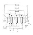
図1は、本発明に係る無電解めっき液の再生装置の一実施態様を示す概略図である。
本発明に係る無電解めっき液の再生装置は、不要イオンが蓄積し劣化した無電解めっき液を電気透析法により再生する装置であって、少なくとも陽極板および陰極板の両極板間に複数の陽イオン交換膜と陰イオン交換膜を交互に配置して、前記陽イオン交換膜と陰イオン交換膜によって仕切られた脱塩室および濃縮室を有する電気透析ユニットと、前記脱塩室に劣化した無電解めっき液を循環して供給する脱塩槽と、前記濃縮室に希薄電解液を循環して供給する濃縮槽と、前記陽極板および陰極板間に電圧を印加して電気透析を行い、劣化した無電解めっき液に蓄積したイオンを脱塩室の無電解めっき液側から濃縮室の希薄電解液側に移行させて除去し、劣化した無電解めっき液を再生する電気透析手段と、前記電気透析により、蓄積した不要イオン濃度が減少していく劣化した無電解めっき液の導電率または不要イオン濃度が増加していく希薄電解液の導電率を測定する導電率計と、前記導電率計により測定された導電率の変化によって電気透析条件を制御する制御手段を具備することを特徴とする。
FIG. 1 is a schematic view showing an embodiment of an electroless plating solution regenerating apparatus according to the present invention.
An electroless plating solution regenerating apparatus according to the present invention is an apparatus for regenerating an electroless plating solution in which unnecessary ions have accumulated and deteriorated by electrodialysis, and includes a plurality of positive electrodes between at least an anode plate and a cathode plate. An ion exchange membrane and an anion exchange membrane are alternately arranged, and an electrodialysis unit having a desalination chamber and a concentration chamber partitioned by the cation exchange membrane and the anion exchange membrane, Desalting tank that circulates and supplies electrolytic plating solution, concentration tank that circulates and supplies dilute electrolytic solution to the concentration chamber, and electrodialyzes by applying voltage between the anode plate and cathode plate to cause deterioration. Electrodialysis means for removing the ions accumulated in the electroless plating solution transferred from the electroless plating solution side of the desalting chamber to the dilute electrolytic solution side of the concentration chamber, and regenerating the deteriorated electroless plating solution, Accumulated due to dialysis A conductivity meter for measuring the conductivity of a deteriorated electroless plating solution whose ion concentration is decreasing or a diluted electrolyte solution whose unnecessary ion concentration is increasing, and the conductivity measured by the conductivity meter Control means for controlling electrodialysis conditions according to changes is provided.
本発明の無電解めっき液(以降、めっき液とも記す。)の再生方法は、再生対象とする劣化しためっき液を電気透析ユニット1の脱塩室8に供給して電気透析を行う。電気透析ユニット1として用いる電気透析装置については特に制限はなく、陽極板2と陰極板3の間に陽イオン交換膜6と陰イオン交換膜7が交互に配列された構造であれば、公知の電気透析ユニット1を特に限定なく使用できる。例えば、両極間に陽イオン交換膜6と陰イオン交換膜7を、それぞれ室枠を介して交互に配列し、これらの両イオン交換膜と室枠によって脱塩室8と濃縮室9とを形成させた構造からなる電気透析ユニット1を用いることができる。
In the method of regenerating the electroless plating solution (hereinafter also referred to as plating solution) of the present invention, the deteriorated plating solution to be regenerated is supplied to the
電気透析ユニット1に用いる膜数、膜面積、脱塩室8および濃縮室9の流路間隔(膜間隔)等は処理するめっき液の種類や処理量によって適宜選択すればよい。
陽イオン交換膜6としては、特に制限されず、例えばセレミオンCMV(AGCエンジニアリング社製)、ネオセプタCM−1(アストム社製)、Nafion324(デュポン社製)等を使用できる。陰イオン交換膜7は、特に制限はされず、セレミオンAMV(AGCエンジニアリング社製)、ネオセプタAM−X(アストム社製)等を使用できる。電気透析ユニット1の両端部に位置する陽極室4、陰極室5には硫酸ナトリウム水溶液など電解質溶液を適宜選択し供給すればよい。一般的に極液の隔膜10は陽イオン交換膜で構成されている。
What is necessary is just to select suitably the number of membranes used for the
The
電気透析の通電条件は、限界電流密度以下であれば通常の運転条件を適用できる。例えば0.1から10A/dm2程度で電気透析を行うことができる。
本発明の再生方法において再生対象とするめっき液は、ニッケル、銅、金などの無電解めっき液である。一般的な無電解めっき液の基本成分は、金属の供給源として、硫酸ニッケル等のニッケル塩、硫酸銅等の銅塩、シアン化金カリウム等の金塩:金属イオンの還元剤として、次亜リン酸ナトリウム、次亜リン酸カリウム、次亜リン酸アンモニウムなどの次亜リン酸塩、ホルムアルデヒド、ホルマリンやジメチルアミノボラン等のアルキルアミノボラン:金属イオンの錯化剤として酢酸、クエン酸、リンゴ酸、乳酸、コハク酸、EDTA等の有機酸:安定剤として鉛やビスマスなどの負触媒金属等が用いられる。さらに必要に応じて、析出促進剤等が含まれる。その組成については特に制限はなく、公知の各種組成の無電解めっき液処理対象とすることができる。しかしながら本発明の再生対象はこれらの成分を含むめっき液に限定されるものではない。
If the electrodialysis energization conditions are below the limit current density, normal operating conditions can be applied. For example it is possible to perform the electrodialysis in 10A / dm 2 about 0.1.
The plating solution to be regenerated in the regeneration method of the present invention is an electroless plating solution of nickel, copper, gold or the like. The basic components of a general electroless plating solution are as follows: As a metal source, nickel salt such as nickel sulfate, copper salt such as copper sulfate, gold salt such as potassium gold cyanide; Hypophosphites such as sodium phosphate, potassium hypophosphite and ammonium hypophosphite, alkylaminoboranes such as formaldehyde, formalin and dimethylaminoborane: acetic acid, citric acid and malic acid as complexing agents for metal ions Organic acids such as lactic acid, succinic acid, EDTA: negative catalytic metals such as lead and bismuth are used as stabilizers. Furthermore, a precipitation accelerator etc. are contained as needed. There is no restriction | limiting in particular about the composition, It can be made into the electroless-plating liquid processing object of well-known various compositions. However, the regeneration object of the present invention is not limited to the plating solution containing these components.
電気透析ユニット1の脱塩槽11に劣化しためっき液を供給し、濃縮槽12には希薄電解液を供給する。劣化しためっき液は、脱塩槽11と脱塩室8を循環させ、希薄電解液は、濃縮槽12と濃縮室9を循環させる。前記陽極板および陰極板間に電源16から電圧を印加して電気透析することによって、劣化した無電解めっき液に蓄積したイオンを脱塩室8の無電解めっき液側から濃縮室9の希薄電解液側に移行させて除去し、劣化した無電解めっき液を再生する。電気透析は、電源16と電気透析ユニット1を含む電気透析手段により行なわれる。
The deteriorated plating solution is supplied to the desalting tank 11 of the
移行させて除去されるイオンは、例えば安定剤の対イオンの陽イオンは陰極側に移動し設置されている陽イオン交換膜で、また還元剤の酸化イオンや金属の対イオンなどの陰イオンは陽極側に移動し設置されている陰イオン交換膜を介して移行する。 The ions removed by migration are, for example, cation exchange membranes, where the cation of the stabilizer counter ion moves to the cathode side, and the anion such as the reducing agent oxide ion or metal counter ion It moves to the anode side and moves through the installed anion exchange membrane.
供給される劣化しためっき液の液温が高いと、電気透析ユニット内の電極、イオン交換膜等に金属が析出し、電気透析の効率が低下する。また、イオン交換膜や配管等の熱による破損や変形が生じ易くなる。液温が低すぎると、脱塩液、濃縮液に含まれる成分が結晶化して配管の目詰まり等が生じ易くなる。このため、処理対象とする無電解めっき液、脱塩液、濃縮液の液温を15から50℃程度に保持することが好ましい。 When the temperature of the deteriorated plating solution supplied is high, metal is deposited on the electrode, ion exchange membrane, etc. in the electrodialysis unit, and the efficiency of electrodialysis decreases. In addition, the ion exchange membrane, piping, and the like are easily damaged or deformed by heat. If the liquid temperature is too low, the components contained in the desalted liquid and the concentrated liquid are crystallized and the pipes are likely to be clogged. For this reason, it is preferable to maintain the liquid temperature of the electroless plating solution, desalting solution, and concentrated solution to be processed at about 15 to 50 ° C.
無電解めっきでは金属の析出とともに減少するイオンに関しては補給が行われるため、これらのイオン濃度は一定に保たれているが、還元剤の酸化生成物や、また金属イオンの補充として主に金属塩を使用するため、ナトリウムやカリウムが消費されることなくめっき液中に蓄積される。 In electroless plating, replenishment is performed for ions that decrease with the deposition of metal, so the concentration of these ions is kept constant. However, the metal salt is mainly used as a replenishment product of the reducing agent and metal ions. Therefore, sodium and potassium are accumulated in the plating solution without being consumed.
劣化しためっき液を脱塩槽11および脱塩室8に循環供給し電解すると、めっき液中の全てのイオンが各割合を持って減少し、濃縮槽12および濃縮室9を循環している希薄電解液に移行するため、希薄電解溶液中のイオンは増加する。移行するイオンのなかで、還元剤の酸化生成物イオンの含有量が多く、さらに電気透析により移行する量も多いため、酸化生成物イオンは全てのイオンの増加、減少を示す代表的なイオンとなる。このため、本発明では、酸化生成物イオン濃度と測定用めっき液の導電率との関係を事前に測定し、その測定結果に基づき検量線を作成し、透析開始時と透析終了時のめっき液、または希薄電解液の導電率を測定し、酸化性生物イオン濃度を推定する。ここで、検量線作成時に使用する測定用めっき液は金属イオンと還元剤イオン量をめっき使用条件時の基準濃度とし、還元剤の酸化生成物イオンの濃度を変えて導電率を測定することで検量線作成を行うことが好ましい。
When the deteriorated plating solution is circulated and supplied to the desalting tank 11 and the
導電率の測定は、導電率計13が用いられ、特に制限はなく、市販のものが用いられる。浸漬型の導電率計の場合には、めっき液または希薄電解液の循環経路内に設置し常にモニターできるのが好ましい。また、通水型の場合には脱塩槽内のめっき液、もしくは濃縮槽内の希薄電解液が常に循環するように設置し、常に導電率をモニターできることが好ましい。 For the measurement of conductivity, a conductivity meter 13 is used, and there is no particular limitation, and a commercially available product is used. In the case of an immersion type conductivity meter, it is preferable that it is installed in the circulation path of the plating solution or dilute electrolyte and can always be monitored. In the case of a water flow type, it is preferable that the plating solution in the desalting tank or the dilute electrolytic solution in the concentration tank is always circulated so that the conductivity can always be monitored.
次に、パソコン14、コントローラー15から構成される制御手段により、前記導電率計により測定された導電率の変化によって電気透析条件を制御する。導電率計13をパソコン14に接続し、めっき液または希薄電解液の導電率を常時パソコンに出力する。そしてあらかじめ作成した検量線で不要イオン濃度を算出し電気透析条件を演算し、コントローラー15で電源16のON、OFFを制御する。これにより、前記電気透析により、蓄積したイオン濃度が減少していくめっき液の導電率、またはイオン濃度が増加していく希薄電解液の導電率の変化によって電気透析条件を制御することができる。
Next, the electrodialysis conditions are controlled by the change in the conductivity measured by the conductivity meter by the control means including the personal computer 14 and the
なお、電気透析条件の演算は以下により行なう。
所定時間内に透析処理が終了されるように、導電率から得られた移動対象イオンの初期濃度(g/L)と目標濃度(g/L)から液量(L)を元に総移動量(g)を算出し、使用するイオン交換膜の固有イオン移動量(g/A・H・dm2)と総膜面積(dm2)から使用する電流値(A)を求め透析を行なうことで一定時間(H)での透析処理が可能となる。この場合透析の終了の判断は設定された導電率値による。更にまた所定の電流値で透析を行なう場合、透析終了時間を同様に演算することも同様に可能である。
The calculation of electrodialysis conditions is performed as follows.
The total transfer amount based on the liquid amount (L) from the initial concentration (g / L) and target concentration (g / L) of the target ions (g / L) obtained from the conductivity so that the dialysis treatment is completed within a predetermined time. (g) is calculated, and by performing a specific ion movement amount (g / a · H · dm 2) and current values to be used from the total membrane area (dm 2) seek (a) dialysis of an ion-exchange membrane used Dialysis treatment can be performed for a certain time (H). In this case, the end of dialysis is determined by the set conductivity value. Furthermore, when dialysis is performed at a predetermined current value, the dialysis end time can be calculated in the same manner.
さらに加えて、電気透析時においてはめっき液中のイオンがめっき液側(脱塩室8)から希薄電解液側(濃縮室9)に移行するとともに、劣化しためっき液中の水もめっき液側(脱塩室8)から希薄電解液(濃縮室9)へと移行する。電気透析後、めっき液を再利用する場合には水の損失分と、電気透析によって除去された必要成分を補正してめっき液の調整をするため、めっき液の導電率は減水を、希薄電解液の導電率は増水を補正する必要がある。水の補正手段としてめっき液の場合は電気透析を行いながら透析開始時点の液量まで水を供給する、もしくは電気透析によって減量した水量を測定し、計算により導電率を補正する方法がある。希薄電解液の場合には電気透析によって増加した水量を測定し、計算により導電率を補正する方法などがある。 In addition, during electrodialysis, ions in the plating solution move from the plating solution side (demineralization chamber 8) to the dilute electrolyte solution side (concentration chamber 9), and water in the deteriorated plating solution also moves to the plating solution side. It moves from (desalting chamber 8) to a dilute electrolyte (concentration chamber 9). When reusing the plating solution after electrodialysis, the plating solution is adjusted by correcting for the loss of water and the necessary components removed by electrodialysis. The conductivity of the liquid needs to be corrected for water increase. In the case of a plating solution as a means for correcting water, there is a method in which water is supplied up to the amount of liquid at the start of dialysis while electrodialysis is performed or the amount of water reduced by electrodialysis is measured and the conductivity is corrected by calculation. In the case of a diluted electrolyte, there is a method of measuring the amount of water increased by electrodialysis and correcting the conductivity by calculation.
以上のように電気透析開始時点の劣化しためっき液の導電率を測定し、めっき液中の還元剤の酸化生成物濃度を推定した後に、電気透析途中で導電率を測定しながら目標とする酸化生成物濃度の導電率になるまで電気透析を行うことで、めっき液中の酸化生成物の濃度を分析しなくても精度良く目標とする再生液とすることができる。 As described above, after measuring the conductivity of the deteriorated plating solution at the start of electrodialysis and estimating the oxidation product concentration of the reducing agent in the plating solution, the target oxidation is measured while measuring the conductivity during electrodialysis. By performing electrodialysis until the conductivity of the product concentration is reached, the target regenerating solution can be accurately obtained without analyzing the concentration of the oxidized product in the plating solution.
以下、実施例を挙げて本発明をさらに詳細に説明する。
実施例1
500Lの無電解ニッケルめっき液を用いてSPC材(鉄素材)の部品に連続的に無電解ニッケルめっき処理を行った。使用しためっき液の組成は下記のとおりである。
Hereinafter, the present invention will be described in more detail with reference to examples.
Example 1
The SPC material (iron material) was continuously subjected to electroless nickel plating using 500 L of electroless nickel plating solution. The composition of the plating solution used is as follows.
ニッケルイオン 5.5g/L
次亜リン酸イオン 20g/L
錯化剤(リンゴ酸等) 60g/L
Nickel ion 5.5g / L
Hypophosphite ion 20g / L
Complexing agent (malic acid, etc.) 60 g / L
[検量線作成]
あらかじめ上記の組成の測定用めっき液に、不要イオンである亜リン酸イオン濃度が25、75、125、175、225g/Lになるように亜燐酸Naで調整して導電率を測定し、亜リン酸濃度と導電率の関係を示す図2を作成した。図2から、下記の式1に示す検量線を求めた。
亜リン酸イオン[g/L]=10×導電率[S/m]−25・・・(式1)
[Create calibration curve]
In the measurement plating solution having the above composition, the conductivity is measured by adjusting with phosphorous acid Na so that the concentration of phosphite ions, which are unnecessary ions, is 25, 75, 125, 175, and 225 g / L. FIG. 2 showing the relationship between phosphoric acid concentration and conductivity was prepared. From FIG. 2, the calibration curve shown in the following
Phosphite ion [g / L] = 10 × Conductivity [S / m] −25 (Formula 1)
[めっき処理]
めっき処理中は無電解ニッケルめっき液は自動コントローラー(カニゼン株式会社 CAAC−752ST)により、ニッケルイオン濃度とpHは自動で管理されている。建浴時にめっき液中に存在するニッケルイオンと等量のニッケルイオンを補充した時点を1ターンとし、5ターンまでめっきを行った。電気透析処理前のめっき液の組成は下記のとおりである。
[Plating treatment]
During the plating process, the nickel ion concentration and pH of the electroless nickel plating solution are automatically managed by an automatic controller (Kanizen Co., Ltd. CAAC-752ST). Plating was performed up to 5 turns, with 1 turn being the time at which nickel ions equivalent to the amount of nickel ions present in the plating solution were replenished during the bathing. The composition of the plating solution before the electrodialysis treatment is as follows.
ニッケルイオン 5.5g/L
次亜リン酸イオン 20g/L
錯化剤(リンゴ酸等) 60g/L
亜リン酸イオン 110から140g/L
Nickel ion 5.5g / L
Hypophosphite ion 20g / L
Complexing agent (malic acid, etc.) 60 g / L
Phosphite ion 110 to 140 g / L
このめっき液を、図1に示す無電解めっき液の再生装置を用いて、以下の条件で電気透析処理を行った。 The plating solution was electrodialyzed under the following conditions using the electroless plating solution regenerating apparatus shown in FIG.
透析時間は10時間と電気透析ユニットで使用した陰イオン交換膜は、AGCエンジニアリング社製のセレミオンAMV、陽イオン交換膜はAGCエンジニアリング社製のセレミオンCMVを用いた。イオン交換膜の膜面積は5dm2、陰イオン交換膜、陽イオン交換膜各150枚ずつを並列に配列して、劣化めっき液を脱塩槽と電気透析ユニットの脱塩室を循環させながら導電率を測定した。 The dialysis time was 10 hours, and the anion exchange membrane used in the electrodialysis unit was Selemion AMV manufactured by AGC Engineering, and the cation exchange membrane was Selemion CMV manufactured by AGC Engineering. The membrane area of the ion exchange membrane is 5 dm 2 , 150 anion exchange membranes and 150 cation exchange membranes are arranged in parallel, and the deteriorated plating solution is conducted while circulating through the desalting tank and the desalting chamber of the electrodialysis unit. The rate was measured.
検量線により、導電率の値から亜リン酸濃度を算出し、劣化しためっき液の導電率が5.0S/m、液中の目標亜リン酸イオン濃度が25g/lになるまで電気透析条件が10時間で一定になるように透析条件を算出した。その結果を表1に示す。算出した電流(A)の拘束で、導電率が5.0S/mになるまで透析処理を行なった。 Calculate phosphite concentration from conductivity value using calibration curve, electrodialysis conditions until conductivity of degraded plating solution is 5.0 S / m and target phosphite ion concentration in solution is 25 g / l The dialysis conditions were calculated so that was constant over 10 hours. The results are shown in Table 1. Dialysis treatment was performed until the conductivity reached 5.0 S / m under the constraint of the calculated current (A).
(電気透析条件の算出)
使用する陰イオン交換膜の固有値として亜燐酸移動量を0.35g/1A/1H/1dm2と液量500Lから、各々総移動量(g)を求め陰イオン交換膜の面積750dm2(150枚*5dm2/1枚)と透析時間10(H)より個別の電流値(A)を算出した。固有亜燐酸移動量は前記導電率測定用溶液から得られた。
(Calculation of electrodialysis conditions)
As the intrinsic value of the anion exchange membrane to be used, the total amount of migration (g) was determined from 0.35 g / 1A / 1H / 1 dm 2 and the amount of liquid 500 L as the phosphite migration amount, and the area of the anion exchange membrane 750 dm 2 (150 sheets) * Each current value (A) was calculated from 5 dm 2 / sheet) and dialysis time 10 (H). Intrinsic phosphorous acid transfer amount was obtained from the conductivity measuring solution.
そして、透析後に亜リン酸イオン濃度が25g/lになっているか、キャピラリー電気泳動装置(Agilent Technologies社製 G1600A)で亜リン酸イオン濃度を測定し確認した。 Then, whether the phosphite ion concentration was 25 g / l after dialysis was confirmed by measuring the phosphite ion concentration with a capillary electrophoresis apparatus (G1600A manufactured by Agilent Technologies).
電気透析ユニットの濃縮室には、予め同様の電気透析を行った際に得られた濃縮液が充填された状態であった。
電気透析ユニットの陽極室、陰極室には10%の硫酸ナトリウム水溶液を循環しながら電解処理を行った。
The concentration chamber of the electrodialysis unit was in a state of being filled with the concentrate obtained when the same electrodialysis was performed in advance.
Electrolysis was performed while circulating a 10% aqueous sodium sulfate solution in the anode chamber and cathode chamber of the electrodialysis unit.
また、劣化しためっき液、または希薄電解液の導電率は導電率計(堀場製作所社製 D−54 流通型導電率電極3652−10D)により随時測定し、パソコンに出力し、電気透析条件を演算し、コントローラーで電源を制御した。
以上の評価を10回行い、その結果を表2に示す。これより、目標の亜リン酸濃度に対し誤差±10%で制御することが可能となった。
In addition, the conductivity of the deteriorated plating solution or dilute electrolyte is measured with a conductivity meter (D-54 flow-type conductivity electrode 3652-10D manufactured by Horiba, Ltd.) as needed, and output to a personal computer to calculate electrodialysis conditions. The power was controlled by the controller.
The above evaluation was performed 10 times, and the results are shown in Table 2. As a result, it was possible to control the target phosphorous acid concentration with an error of ± 10%.

実施例2
実施例1と同じように500Lの無電解ニッケルめっきを用いてSPC材部品を被めっき物として連続的に処理し、5ターン程度無電解ニッケルめっきを行った。このめっき液の組成を以下に示す。
Example 2
As in Example 1, 500 L of electroless nickel plating was used to continuously treat the SPC material part as an object to be plated, and electroless nickel plating was performed for about 5 turns. The composition of this plating solution is shown below.
ニッケルイオン 5.5g/L
次亜リン酸イオン 20g/L
錯化剤(リンゴ酸等) 60g/L
亜リン酸イオン濃度 110〜140g/L
Nickel ion 5.5g / L
Hypophosphite ion 20g / L
Complexing agent (malic acid, etc.) 60 g / L
Phosphite ion concentration 110-140g / L
このめっき液を実施例1と同じ条件で電気透析を行い、めっき液からの脱水を考慮して、計算によって導電率の補正を行いながら、亜リン酸イオン濃度が25g/Lになるまで電気透析を行い、実施例1と同じ評価を行った。 This plating solution is electrodialyzed under the same conditions as in Example 1, and the electrodialysis is performed until the phosphite ion concentration reaches 25 g / L while correcting the conductivity by calculation in consideration of dehydration from the plating solution. The same evaluation as in Example 1 was performed.
めっき液からの脱水による導電率の補正は、液面計から脱水量を算出し元の500L相当に換算することにより行なった。
以上を5回繰り返し行い、その結果を表3に示す。これより、目標の亜リン酸濃度に対し誤差±5%で制御することが可能となった。電気透析による水の移動を補正し導電率で管理を行うと、さらに高精度な管理が出来ることが得られた。
The correction of the conductivity by dehydration from the plating solution was performed by calculating the dehydration amount from a liquid level gauge and converting it to the original equivalent of 500L.
The above was repeated 5 times, and the results are shown in Table 3. As a result, it became possible to control the target phosphorous acid concentration with an error of ± 5%. When the movement of water due to electrodialysis was corrected and management was performed using conductivity, it was possible to perform more accurate management.
比較例1
実施例1と同じように500Lの無電解ニッケルめっき液を用いてSPC材部品を被めっき物として連続的に処理し、5ターン程度無電解ニッケルめっきを行った。このめっき液の組成を以下に示す。
Comparative Example 1
In the same manner as in Example 1, using 500 L of electroless nickel plating solution, the SPC material parts were continuously processed as an object to be plated, and electroless nickel plating was performed for about 5 turns. The composition of this plating solution is shown below.
ニッケルイオン 5.5g/L
次亜リン酸イオン 20g/L
錯化剤(リンゴ酸等) 60g/L
亜リン酸イオン濃度 110〜140g/L
Nickel ion 5.5g / L
Hypophosphite ion 20g / L
Complexing agent (malic acid, etc.) 60 g / L
Phosphite ion concentration 110-140g / L
このめっき液について、従来の実験から求めた、この実験装置固有の亜リン酸イオンの除去量と時間、電流量の関係から、亜リン酸イオン濃度が25g/Lになるまでにかかる透析時間を4時間と算出し、実施例1と同じ条件で電気透析を行った。電気透析後、めっき液の亜リン酸イオン濃度をキャピラリー電気泳動装置で測定し、確認した。 For this plating solution, the dialysis time required for the phosphite ion concentration to reach 25 g / L based on the relationship between the amount of phosphite ion removal inherent in this experimental apparatus, the time, and the amount of current obtained from a conventional experiment. It was calculated as 4 hours, and electrodialysis was performed under the same conditions as in Example 1. After electrodialysis, the phosphite ion concentration of the plating solution was measured with a capillary electrophoresis apparatus and confirmed.
以上を10回行い、その結果を表4に示す。目標の亜リン酸イオン濃度に対し、±20%の誤差が生じた。 The above was performed 10 times and the results are shown in Table 4. An error of ± 20% occurred with respect to the target phosphite ion concentration.
本発明の無電解めっき液の再生方法は、劣化した無電解めっき液の蓄積した不要イオンの濃度が変動する場合でも、目標とする濃度まで精度良く除去できるので、電気透析による高純度薬品の製造や醤油等の脱塩として利用することができる。 The method for regenerating an electroless plating solution of the present invention can accurately remove a target concentration even when the concentration of accumulated unnecessary ions in a deteriorated electroless plating solution fluctuates. It can be used for desalination of soy sauce and soy sauce.
1 電気透析ユニット
2 陽極板
3 陰極板
4 陽極室
5 陰極室
6 陽イオン交換膜
7 陰イオン交換膜
8 脱塩室(めっき液)
9 濃縮室(希薄電解液)
10 隔膜
11 脱塩槽(めっき液)
12 濃縮槽(希薄電解液)
13 導電率計
14 パソコン
15 コントローラー
16 電源
1
9 Concentration chamber (dilute electrolyte)
10 Diaphragm 11 Desalination tank (plating solution)
12 Concentration tank (dilute electrolyte)
13 Conductivity meter 14
Claims (4)
Priority Applications (1)
| Application Number | Priority Date | Filing Date | Title |
|---|---|---|---|
| JP2008198700A JP5553492B2 (en) | 2008-07-31 | 2008-07-31 | Method and apparatus for regenerating electroless plating solution |
Applications Claiming Priority (1)
| Application Number | Priority Date | Filing Date | Title |
|---|---|---|---|
| JP2008198700A JP5553492B2 (en) | 2008-07-31 | 2008-07-31 | Method and apparatus for regenerating electroless plating solution |
Related Child Applications (1)
| Application Number | Title | Priority Date | Filing Date |
|---|---|---|---|
| JP2014109575A Division JP6223282B2 (en) | 2014-05-27 | 2014-05-27 | Method and apparatus for regenerating electroless plating solution |
Publications (2)
| Publication Number | Publication Date |
|---|---|
| JP2010037573A true JP2010037573A (en) | 2010-02-18 |
| JP5553492B2 JP5553492B2 (en) | 2014-07-16 |
Family
ID=42010429
Family Applications (1)
| Application Number | Title | Priority Date | Filing Date |
|---|---|---|---|
| JP2008198700A Active JP5553492B2 (en) | 2008-07-31 | 2008-07-31 | Method and apparatus for regenerating electroless plating solution |
Country Status (1)
| Country | Link |
|---|---|
| JP (1) | JP5553492B2 (en) |
Cited By (4)
| Publication number | Priority date | Publication date | Assignee | Title |
|---|---|---|---|---|
| CN102373341A (en) * | 2010-08-12 | 2012-03-14 | 独立行政法人日本原子力研究开发机构 | Recovering method and devcie of lithium |
| CN102976454A (en) * | 2012-10-29 | 2013-03-20 | 中国科学院过程工程研究所 | Method for separating cations of NH4<+> and Mg<2+> with same electric properties in fermentation wasterwater by using packed bed electrodialyzer |
| JP2014079724A (en) * | 2012-10-18 | 2014-05-08 | Kurita Water Ind Ltd | Regeneration process and apparatus for amine liquid |
| EP2714234A4 (en) * | 2011-05-26 | 2015-03-18 | Coway Co Ltd | Active regeneration method for deionization module and water treatment apparatus using the same |
Families Citing this family (1)
| Publication number | Priority date | Publication date | Assignee | Title |
|---|---|---|---|---|
| CN221354668U (en) | 2021-06-16 | 2024-07-16 | 株式会社村田制作所 | Multilayer substrate |
Citations (8)
| Publication number | Priority date | Publication date | Assignee | Title |
|---|---|---|---|---|
| JPS52133083A (en) * | 1976-04-30 | 1977-11-08 | Hitachi Cable Ltd | Electrodialyzer |
| JPS56136968A (en) * | 1980-03-27 | 1981-10-26 | Hitachi Ltd | Method and apparatus for selectively deionizing chemical copper plating bath |
| JPH01107810A (en) * | 1987-10-20 | 1989-04-25 | Tosoh Corp | Operation of electrodialysis device |
| JPH0397874A (en) * | 1989-09-01 | 1991-04-23 | Internatl Business Mach Corp <Ibm> | Method of removing and obtaining ethylenediamine tetraacetic acid continuously from process water of electroless copper plating |
| JPH10195670A (en) * | 1996-12-27 | 1998-07-28 | Nippon Chem Ind Co Ltd | System for circulating electroless nickel plating solution |
| JP2001314864A (en) * | 2000-05-08 | 2001-11-13 | Japan Organo Co Ltd | Treating method for waste liquid from polarizing plate manufacturing |
| JP2004052029A (en) * | 2002-07-18 | 2004-02-19 | Okuno Chem Ind Co Ltd | Treatment method and treatment apparatus for electroless nickel-plating liquid |
| JP2007291465A (en) * | 2006-04-26 | 2007-11-08 | Nippon Kanizen Kk | Device for prolonging lifetime of electroless nickel-plating liquid |
-
2008
- 2008-07-31 JP JP2008198700A patent/JP5553492B2/en active Active
Patent Citations (8)
| Publication number | Priority date | Publication date | Assignee | Title |
|---|---|---|---|---|
| JPS52133083A (en) * | 1976-04-30 | 1977-11-08 | Hitachi Cable Ltd | Electrodialyzer |
| JPS56136968A (en) * | 1980-03-27 | 1981-10-26 | Hitachi Ltd | Method and apparatus for selectively deionizing chemical copper plating bath |
| JPH01107810A (en) * | 1987-10-20 | 1989-04-25 | Tosoh Corp | Operation of electrodialysis device |
| JPH0397874A (en) * | 1989-09-01 | 1991-04-23 | Internatl Business Mach Corp <Ibm> | Method of removing and obtaining ethylenediamine tetraacetic acid continuously from process water of electroless copper plating |
| JPH10195670A (en) * | 1996-12-27 | 1998-07-28 | Nippon Chem Ind Co Ltd | System for circulating electroless nickel plating solution |
| JP2001314864A (en) * | 2000-05-08 | 2001-11-13 | Japan Organo Co Ltd | Treating method for waste liquid from polarizing plate manufacturing |
| JP2004052029A (en) * | 2002-07-18 | 2004-02-19 | Okuno Chem Ind Co Ltd | Treatment method and treatment apparatus for electroless nickel-plating liquid |
| JP2007291465A (en) * | 2006-04-26 | 2007-11-08 | Nippon Kanizen Kk | Device for prolonging lifetime of electroless nickel-plating liquid |
Cited By (4)
| Publication number | Priority date | Publication date | Assignee | Title |
|---|---|---|---|---|
| CN102373341A (en) * | 2010-08-12 | 2012-03-14 | 独立行政法人日本原子力研究开发机构 | Recovering method and devcie of lithium |
| EP2714234A4 (en) * | 2011-05-26 | 2015-03-18 | Coway Co Ltd | Active regeneration method for deionization module and water treatment apparatus using the same |
| JP2014079724A (en) * | 2012-10-18 | 2014-05-08 | Kurita Water Ind Ltd | Regeneration process and apparatus for amine liquid |
| CN102976454A (en) * | 2012-10-29 | 2013-03-20 | 中国科学院过程工程研究所 | Method for separating cations of NH4<+> and Mg<2+> with same electric properties in fermentation wasterwater by using packed bed electrodialyzer |
Also Published As
| Publication number | Publication date |
|---|---|
| JP5553492B2 (en) | 2014-07-16 |
Similar Documents
| Publication | Publication Date | Title |
|---|---|---|
| JP5553492B2 (en) | Method and apparatus for regenerating electroless plating solution | |
| US9702044B2 (en) | Method for regenerating plating liquid, plating method, and plating apparatus | |
| JP5158634B2 (en) | Treatment method of electroless nickel plating solution | |
| CN112714803B (en) | Plating solution production and regeneration process and device for insoluble anode acid copper electroplating | |
| JP2015167922A (en) | Electrodialyzer, electrodialysis method, and plating treatment system | |
| KR20150113118A (en) | Rechargeable electrochemical cells | |
| TW467966B (en) | Method and device for regenerating an electroless metal deposition bath by electrodialysis | |
| JP2015108609A (en) | METHOD AND APPARATUS FOR ELECTRODEPOSITION OF Co AND Fe | |
| KR101267201B1 (en) | Method for recovering precious-metal ions from plating wastewater | |
| JP6223282B2 (en) | Method and apparatus for regenerating electroless plating solution | |
| JP2002322600A (en) | Method for conserving electrolyte | |
| JP5354871B2 (en) | Electrolyte solution regeneration method and regeneration device | |
| JP4025987B2 (en) | Method and apparatus for processing electroless nickel plating solution | |
| JP4991655B2 (en) | Electrodialysis machine | |
| JP5393834B2 (en) | Electrodialysis apparatus for removing a plurality of ions to be removed from a liquid containing an electrolyte | |
| JP5822235B2 (en) | Method for removing oxidized nitrogen | |
| JP5908372B2 (en) | Electrolysis electrode | |
| JP4517177B2 (en) | Treatment method of electroless nickel plating solution | |
| JPH06158397A (en) | Method for electroplating metal | |
| JPS637382A (en) | Method and apparatus for regenerating electroless copper plating liquid | |
| JPH01119679A (en) | Method for administrating chemical copper plating liquid | |
| US20210079551A1 (en) | Method and device for filtering a platinum bath by electrodialysis | |
| JPS5824520B2 (en) | Denka etching method | |
| JP2024127782A (en) | How to regenerate electroless nickel plating baths | |
| JP2022097062A (en) | Electrodialyzer, water treatment system and method |
Legal Events
| Date | Code | Title | Description |
|---|---|---|---|
| RD03 | Notification of appointment of power of attorney |
Free format text: JAPANESE INTERMEDIATE CODE: A7423 Effective date: 20100629 |
|
| RD04 | Notification of resignation of power of attorney |
Free format text: JAPANESE INTERMEDIATE CODE: A7424 Effective date: 20100831 |
|
| A521 | Request for written amendment filed |
Free format text: JAPANESE INTERMEDIATE CODE: A523 Effective date: 20100824 |
|
| RD04 | Notification of resignation of power of attorney |
Free format text: JAPANESE INTERMEDIATE CODE: A7424 Effective date: 20101227 |
|
| A621 | Written request for application examination |
Free format text: JAPANESE INTERMEDIATE CODE: A621 Effective date: 20110801 |
|
| RD03 | Notification of appointment of power of attorney |
Free format text: JAPANESE INTERMEDIATE CODE: A7423 Effective date: 20120914 |
|
| A977 | Report on retrieval |
Free format text: JAPANESE INTERMEDIATE CODE: A971007 Effective date: 20130528 |
|
| A131 | Notification of reasons for refusal |
Free format text: JAPANESE INTERMEDIATE CODE: A131 Effective date: 20130604 |
|
| A521 | Request for written amendment filed |
Free format text: JAPANESE INTERMEDIATE CODE: A523 Effective date: 20130805 |
|
| TRDD | Decision of grant or rejection written | ||
| A01 | Written decision to grant a patent or to grant a registration (utility model) |
Free format text: JAPANESE INTERMEDIATE CODE: A01 Effective date: 20140428 |
|
| A61 | First payment of annual fees (during grant procedure) |
Free format text: JAPANESE INTERMEDIATE CODE: A61 Effective date: 20140527 |
|
| R150 | Certificate of patent or registration of utility model |
Ref document number: 5553492 Country of ref document: JP Free format text: JAPANESE INTERMEDIATE CODE: R150 |
|
| R250 | Receipt of annual fees |
Free format text: JAPANESE INTERMEDIATE CODE: R250 |
|
| R250 | Receipt of annual fees |
Free format text: JAPANESE INTERMEDIATE CODE: R250 |
|
| R250 | Receipt of annual fees |
Free format text: JAPANESE INTERMEDIATE CODE: R250 |
|
| R250 | Receipt of annual fees |
Free format text: JAPANESE INTERMEDIATE CODE: R250 |
|
| R250 | Receipt of annual fees |
Free format text: JAPANESE INTERMEDIATE CODE: R250 |
|
| R250 | Receipt of annual fees |
Free format text: JAPANESE INTERMEDIATE CODE: R250 |
|
| R250 | Receipt of annual fees |
Free format text: JAPANESE INTERMEDIATE CODE: R250 |
|
| R250 | Receipt of annual fees |
Free format text: JAPANESE INTERMEDIATE CODE: R250 |