JP2010036171A - Adhesive application method and adhesive application device - Google Patents
Adhesive application method and adhesive application device Download PDFInfo
- Publication number
- JP2010036171A JP2010036171A JP2008205493A JP2008205493A JP2010036171A JP 2010036171 A JP2010036171 A JP 2010036171A JP 2008205493 A JP2008205493 A JP 2008205493A JP 2008205493 A JP2008205493 A JP 2008205493A JP 2010036171 A JP2010036171 A JP 2010036171A
- Authority
- JP
- Japan
- Prior art keywords
- adhesive
- surface plate
- coating
- base material
- substrate
- Prior art date
- Legal status (The legal status is an assumption and is not a legal conclusion. Google has not performed a legal analysis and makes no representation as to the accuracy of the status listed.)
- Granted
Links
Images


Landscapes
- Coating Apparatus (AREA)
- Application Of Or Painting With Fluid Materials (AREA)
Abstract
Description
本発明は、例えば非接触ICカードを作製する際、イントレットシートに積層される基材の上に予め接着剤を塗布する接着剤塗布方法および接着剤塗布装置に関する。 The present invention relates to an adhesive application method and an adhesive application device for applying an adhesive in advance on a base material laminated on an inlet sheet, for example, when producing a non-contact IC card.
近年、リーダ・ライタ等の外部装置と非接触で通信する非接触ICカードが普及しつつある。非接触ICカードの需要は、今後、急速な勢いで拡大していくものと予想されており、これにともなって、高品質の非接触ICカードを低コストで製造することが強く望まれている。 In recent years, contactless IC cards that communicate with external devices such as readers / writers in a contactless manner are becoming popular. The demand for non-contact IC cards is expected to expand rapidly in the future, and accordingly, it is strongly desired to manufacture high-quality non-contact IC cards at low cost. .
非接触ICカードは、第1基材と、第1基材の一方の面に設けられた第1接着剤層とを含む表面側基板と、第2基材と、第2基材の一方の面に設けられた第2接着剤層とを含む裏面側基板とを備えている。また、表面側基板と裏面側基板間に、インレット用基材と、インレット用基材上に設けられたICチップと、ICチップに対応して設けられたアンテナとを含むインレットシートが設けられている(例えば、特許文献1参照) 。このような構成からなる非接触ICカードにおいて、表面側基板の第1基材および裏面側基板の第2基材は所謂枚葉状に予め各々断裁され、かつ各々印刷されている。このような場合、第1基材および第2基材に施された印刷を合わせるために、表面側基板と裏面側基板とインレットシートとを精確に位置合わせし、ラミネートする必要がある。
しかしながら、例えば表面側基板とインレットシートとを位置合わせする場合、表面側基板の第1接着剤層がタック性(粘着性) を有しているため、表面側基板とインレットシートと が接触すると容易に接合されることがある。この場合は、表面側基板とインレットシートとを位置合わせしながらラミネートすることが困難となる。同様に、裏面側基板の第2接着剤層もタック性を有しているため、裏面側基板とインレットシートとが接触すると容易に接合されることがあり、この場合も同様に、裏面側基板とインレットシートとを位置合わせしながらラミネートすることが困難となる。 However, for example, when aligning the front side substrate and the inlet sheet, the first adhesive layer of the front side substrate has tackiness (adhesiveness), so it is easy to contact the front side substrate and the inlet sheet. May be joined. In this case, it is difficult to laminate the front side substrate and the inlet sheet while aligning them. Similarly, since the second adhesive layer of the back side substrate also has tackiness, it may be easily joined when the back side substrate and the inlet sheet come into contact with each other. It becomes difficult to laminate while aligning the inlet sheet and the inlet sheet.
そこで、表面側基板の第1接着剤層、および裏面側基板の第2接着剤層のタック性を喪失させることで、表面側基板と裏面側基板とインレットシートとをより精確に位置合わせし、ラミネートすることが考えられている。各基材の接着剤層のタック性を喪失させるためには、基材に接着剤が塗布された直後に接着剤を冷却して、接着剤を固化させ、基材上に接着剤層を形成させることが有効である。しかしながら、ローラーに巻きつけられている基材を順次送り出しながら、基材の上に接着剤を塗布する方法においては、基材に接着剤が塗布された直後に接着剤を冷却することは困難である。 Therefore, by losing the tackiness of the first adhesive layer on the front side substrate and the second adhesive layer on the back side substrate, the front side substrate, the back side substrate and the inlet sheet are more accurately aligned, Lamination is considered. In order to lose the tackiness of the adhesive layer of each substrate, the adhesive is cooled immediately after the adhesive is applied to the substrate to solidify the adhesive and form an adhesive layer on the substrate. It is effective to make it. However, it is difficult to cool the adhesive immediately after the adhesive is applied to the base material in the method of applying the adhesive onto the base material while sequentially feeding the base material wound around the roller. is there.
本発明は、このような点を考慮してなされたものであり、基材に接着剤が塗布された直後に接着剤を冷却することができる接着剤塗布方法および接着剤塗布装置を提供することを目的とする。 The present invention has been made in consideration of the above points, and provides an adhesive application method and an adhesive application device capable of cooling an adhesive immediately after the adhesive is applied to a substrate. With the goal.
本発明は、冷却機構が設けられている定盤上に基材を配置する工程と、基材が配置された定盤を、基材の幅方向に延びるよう配置された塗布機構に対して塗布機構の配置方向に直交する方向に相対移動させて、塗布機構により基材上に接着剤を塗布する工程と、基材上に塗布された接着剤が固化されるよう、接着剤を定盤の冷却機構により冷却する工程と、を備えたことを特徴とする接着剤塗布方法である。 The present invention applies a step of disposing a base material on a surface plate provided with a cooling mechanism, and a surface plate on which the base material is disposed on an application mechanism disposed so as to extend in the width direction of the base material. Relative movement in the direction perpendicular to the arrangement direction of the mechanism, the step of applying the adhesive on the substrate by the application mechanism, and the adhesive of the surface plate so that the adhesive applied on the substrate is solidified And a step of cooling by a cooling mechanism.
本発明は、塗布機構により基材上に接着剤を塗布する工程は、塗布機構に対して予め定盤を相対移動させておき、基材の塗布領域始端が塗布機構に達した際、塗布機構により接着剤の塗布を開始する工程を有することを特徴とする接着剤塗布方法である。 In the present invention, the step of applying the adhesive onto the base material by the application mechanism is performed by moving the surface plate relative to the application mechanism in advance, and when the start of the application area of the base material reaches the application mechanism. The method for applying an adhesive comprises the step of starting the application of the adhesive.
本発明は、塗布機構により基材上に接着剤を塗布する工程は、基材の塗布領域終端が塗布機構に達した際、塗布機構による塗布を停止する工程と、その後も、塗布機構に対して定盤の相対移動を続ける工程とを有することを特徴とする接着剤塗布方法である。 In the present invention, the step of applying the adhesive on the base material by the coating mechanism includes the step of stopping the coating by the coating mechanism when the coating region end of the base material reaches the coating mechanism, and thereafter the coating mechanism. And a step of continuing relative movement of the surface plate.
本発明は、基材が配置される定盤と、定盤上方に設けられ、基材の幅方向に延びるよう配置され、基材に接着剤を塗布する塗布機構と、定盤に設けられ、基材上に塗布された接着剤を固化させる冷却機構と、を備え、定盤は、塗布機構に対して塗布機構の配置方向に直交する方向に相対移動可能となることを特徴とする接着剤塗布装置である。 The present invention is provided with a surface plate on which a base material is disposed, an upper portion of the surface plate, disposed so as to extend in the width direction of the base material, an application mechanism for applying an adhesive to the base material, and a surface plate. A cooling mechanism for solidifying the adhesive applied on the substrate, and the surface plate is movable relative to the application mechanism in a direction perpendicular to the direction of arrangement of the application mechanism. It is a coating device.
本発明は、冷却機構は、冷媒による冷却機構であることを特徴とする接着剤塗布装置である。 The present invention is the adhesive applicator characterized in that the cooling mechanism is a cooling mechanism using a refrigerant.
本発明は、冷却機構は、空冷による冷却機構であることを特徴とする接着剤塗布装置である。 The present invention is the adhesive coating device, wherein the cooling mechanism is a cooling mechanism by air cooling.
本発明は、冷却機構は、冷却する際の冷却速度を制御可能であることを特徴とする接着剤塗布装置である。 The present invention is the adhesive application device characterized in that the cooling mechanism can control the cooling rate at the time of cooling.
本発明は、接着剤は、湿気硬化性ウレタン樹脂からなることを特徴とする接着剤塗布装置である。 The present invention is the adhesive application device, wherein the adhesive is made of a moisture curable urethane resin.
本発明によれば、定盤上に基材を配置した後、定盤を、基材の幅方向に延びるよう配置された塗布機構に対して塗布機構の配置方向に直交する方向に相対移動させて、塗布機構により基材上に接着剤を塗布する。このため、定盤が移動する速度、および塗布機構が接着剤を吐出するタイミングが制御されることで、基材上に塗布される接着剤の厚さが制御される。これによって、基材上に、厚みの均一な接着剤層を形成することができる。
また、本発明によれば、基材が配置された定盤に冷却機構が設けられている。このため、塗布機構により基材上に接着剤が塗布された後、接着剤が定盤の冷却機構により冷却される。これによって、基材上に接着剤が塗布された直後に、接着剤を固化させることができる。
According to the present invention, after the base material is disposed on the surface plate, the surface plate is moved relative to the coating mechanism disposed so as to extend in the width direction of the base material in a direction orthogonal to the direction in which the coating mechanism is disposed. Then, an adhesive is applied onto the substrate by an application mechanism. For this reason, the thickness of the adhesive applied onto the substrate is controlled by controlling the speed at which the surface plate moves and the timing at which the application mechanism discharges the adhesive. Thereby, an adhesive layer having a uniform thickness can be formed on the substrate.
Moreover, according to this invention, the cooling mechanism is provided in the surface plate in which the base material is arrange | positioned. For this reason, after an adhesive agent is apply | coated on a base material by an application | coating mechanism, an adhesive agent is cooled by the cooling mechanism of a surface plate. Thus, the adhesive can be solidified immediately after the adhesive is applied on the substrate.
第1の実施の形態
以下、図面を参照して、本発明の第1の実施の形態について説明する。ここで、図1乃至図4は、本発明の第1の実施の形態における接着剤塗布方法および接着剤塗布装置を示す図である。このうち図1は、本発明の第1の実施の形態における接着剤塗布装置を示す図であり、図2は、本発明の第1の実施の形態において、基材上に形成された接着剤層を示す図である。図3は、本発明の第1の実施の形態における接着剤塗布方法を示す図であり、図4は、本発明の第1の実施の形態において、基材上に形成された接着剤層の厚さを示す図である。また、図5は、接着剤層が形成された基材を有する非接触ICカードを示す図である。加えて、図6は、本発明の第1の実施の形態における接着剤塗布方法を用いない場合の接着剤塗布方法を示す図であり、図7は、本発明の第1の実施の形態における接着剤塗布方法を用いない場合に、基材上に形成された接着剤層の厚さを示す図である。
First Embodiment Hereinafter, a first embodiment of the present invention will be described with reference to the drawings. Here, FIG. 1 to FIG. 4 are diagrams showing an adhesive application method and an adhesive application device according to the first embodiment of the present invention. Among these, FIG. 1 is a figure which shows the adhesive agent coating apparatus in the 1st Embodiment of this invention, FIG. 2 is the adhesive agent formed on the base material in the 1st Embodiment of this invention. It is a figure which shows a layer. FIG. 3 is a diagram showing an adhesive application method in the first embodiment of the present invention, and FIG. 4 is a diagram of an adhesive layer formed on a substrate in the first embodiment of the present invention. It is a figure which shows thickness. FIG. 5 is a diagram showing a non-contact IC card having a base material on which an adhesive layer is formed. In addition, FIG. 6 is a diagram showing an adhesive application method when the adhesive application method according to the first embodiment of the present invention is not used, and FIG. 7 is a diagram according to the first embodiment of the present invention. It is a figure which shows the thickness of the adhesive bond layer formed on the base material when not using an adhesive agent coating method.
接着剤、接着剤層
まず図5により、非接触ICカードについて説明する。ここで、非接触ICカードは、リーダ・ライタ等の外部装置と非接触で通信することができるものである。
Adhesive, Adhesive Layer First, a non-contact IC card will be described with reference to FIG. Here, the contactless IC card can communicate with an external device such as a reader / writer in a contactless manner.
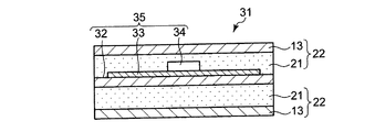
図5に示すように、非接触ICカード31は、基材13と、基材13上に形成された接着剤層21とを有する一対の基板22を備え、一対の基板22は、接着剤層21が向かい合うように対向して配置されている。そして、一対の基板22の間にインレットシート35が挟持され、各基板22とイントレットシートとが張り合わされている。このうちインレットシート35は、インレット用基材32と、インレット用基材32上に設けられたアンテナ33と、アンテナ33に対応して設けられたICチップ34とを有している。なお、一対の基板22とイントレットシートとを張り合わせる際、一対の基板22とイントレットシートとの間の位置合わせを精確に行うためには、前述のとおり、各基材13上に形成されている接着剤層21がタック性(粘着性)を有していないことが好ましい。
As shown in FIG. 5, the
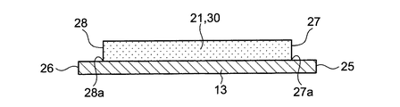
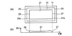
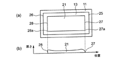
次に図2を参照して、接着剤層21について説明する。基材13上の接着剤層21は、後述するように、基材13上に接着剤30が塗布され、塗布された接着剤30が固化されることにより形成される。また、図2に示すように、接着剤層21の始端27は、基材13の前端25よりも内側に位置している。同様に、接着剤層21の終端28は、基材13の後端26よりも内側に位置している。そして、基材13の塗布領域始端27aが接着剤層21の始端27に対応し、基材13の塗布領域終端28aが接着剤層21の終端28に対応する。なお、接着剤層21の始端27は、基材13の前端25よりも内側に位置し、接着剤層21の終端28は、基材13の後端26よりも内側に位置しているが、例えば接着剤層21の始端27は、基材13の前端25と略同一鉛直線上に位置していてもよく、また接着剤層21の終端28は、基材13の後端26と略同一鉛直線上に位置していてもよい。なお、略同一とは、本発明の趣旨を失わない範囲で、同一に近い範囲を含むことを意味する。
Next, the
また、接着剤層21を形成する接着剤30は、湿気硬化型ウレタン樹脂からなっている。なお、湿気硬化型ウレタン樹脂からなる接着剤30は、常温における気中環境下に急冷された場合、数秒〜数十秒でそのタック性が喪失されて固化する。
さらに、接着剤層21は、ICチップ34の厚さよりも厚く形成されている。また、接着剤層21は所定の弾性を有しており、このため、非接触ICカード31のうちICチップ34が配置されている部分が他の部分と比べて凸状に突出することはなく、非接触ICカード31の表面を平坦にすることができる。
The adhesive 30 forming the
Further, the
接着剤塗布装置
次に、図1により、接着剤塗布装置10について説明する。接着剤塗布装置10は、基材13が配置される定盤11と、基材13に対して接着剤30を塗布する塗布機構15とを備えている。この場合、塗布機構15は、定盤11の上方に設けられ、基材13の幅方向に延びるよう配置されている。また定盤11には、基材13上に塗布された接着剤30を固化させる冷却機構12が設けられている。
図1(a)(b)に示すように、冷却機構12は、定盤11の内部に形成された、冷媒(図示せず)が循環する冷媒流路12aと、ホース12bを介して定盤11内の冷媒流路12aに冷媒を循環させる冷媒循環装置12cとを有する。冷媒としては、例えば水や油が用いられる。また、冷媒循環装置12cから送られてくる冷媒の温度および流速は、制御装置50により制御されており、これにより、基材13上に塗布された接着剤30を冷却する速度を制御することができる。
Adhesive Application Device Next, the
As shown in FIGS. 1 (a) and 1 (b), the
次に、塗布機構15について説明する。塗布機構15は、基材13の幅方向に対応する幅を有し、接着剤を基材13上に塗布する塗布ダイヘッド17と、塗布ダイヘッド17の上面に設けられ、塗布ダイヘッド17の幅方向に並んだ複数、例えば5つの接着剤供給機構16とを有している。各接着剤供給機構16はホース19を介して接着剤タンク18に接続されており、各接着剤供給機構16の内部に設けられている弁(図示せず)が開かれることにより、接着剤タンク18から塗布ダイヘッド17へ接着剤30が供給される。各接着剤供給機構16の内部に設けられている弁の開閉は、それぞれ独立に制御装置50により制御される。
Next, the
また、塗布ダイヘッド17の下端には、基材13の幅方向に対応する幅を有し、塗布ダイヘッド17に供給された接着剤30を基材13上に吐出する開口部17aが形成されている。
制御装置50により各接着剤供給機構16の内部に設けられている弁が開かれると、接着剤30が各接着剤供給機構16を介して塗布ダイヘッド17に供給され、供給された接着剤30は、開口部17aから基材13上に吐出される。このとき、基材13が配置された定盤11が、塗布機構15に対して、後述するように塗布機構15の配置方向に直交する方向に移動されることにより、接着剤30が基材13上に均一に塗布される。
In addition, an opening 17 a that has a width corresponding to the width direction of the
When the valve provided inside each
次に、基材13が配置される定盤11について説明する。定盤11は、駆動機構14により、塗布機構15の配置方向に直交する方向に移動されることができる。この場合、駆動機構14は、定盤11を下方から支持する搬送台14aと、搬送台14aを下方から支持するとともに、塗布機構15の配置方向に直交する方向に延びている一対のレール14bと、搬送台14aの側面に固定されるとともに、塗布機構15の配置方向に伸縮するピストンロッド14cとを有する。そして、駆動機構14のピストンロッド14cが伸縮することにより、搬送台14aに支持されている定盤11が、塗布機構15に対して塗布機構15の配置方向に直交する方向に移動することが可能となる。駆動機構14のピストンロッド14cの伸縮速度は、制御装置50により制御される。
Next, the
接着剤塗布方法
次に、図1乃至図4により、接着剤の塗布方法について説明する。
Adhesive Application Method Next, an adhesive application method will be described with reference to FIGS.
まず、図1に示すように、冷却機構12が設けられている定盤11上に基材13が配置される。次に、図3に示す接着剤塗布方法に従って、制御装置50により、塗布機構15が接着剤30を吐出するタイミングと定盤11の移動速度とが制御される。
First, as shown in FIG. 1, the
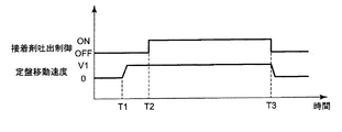
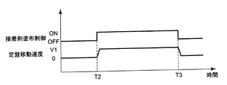
この場合、まず定盤11は、基材13のうち接着剤層21の始端27に対応する塗布領域始端27aが塗布機構15よりも後方(図1において左側)に位置するように配置される。次に、定盤11を、塗布機構15の配置方向に直交する方向において、前方(図1において右側)に向って、移動速度がV1になるよう移動させる(時間=T1)。その後、基材13のうち接着剤層21の始端27に対応する塗布領域始端27aが塗布機構15の直下に到達したとき、定盤11を速度V1で移動させた状態で、塗布機構15の各接着剤供給機構16の内部に設けられている弁(図示せず)が開かれ、これによって、塗布ダイヘッド17へ接着剤30が供給される(時間=T2)。供給された接着剤30は塗布ダイヘッド17の開口部17aから吐出され、この結果、定盤11が塗布機構15に対して速度V1で移動する間、基材13上に接着剤30が均一に塗布される。
In this case, the
その後、基材13のうち接着剤層21の終端28に対応する塗布領域終端28aが塗布機構15の直下に到達すると、塗布機構15の各接着剤供給機構16の内部に設けられている弁(図示せず)が閉じられ、塗布ダイヘッド17への接着剤30の供給が遮断される。同時に、制御装置50により定盤11の移動も停止される(時間=T3)。
Thereafter, when the
次に、基材13上に塗布された接着剤30が固化されるよう、接着剤30が定盤11に設けられている冷却機構12により冷却される。この際、冷却速度が接着剤30の粘性に応じた最適値となるよう、制御装置50により、定盤11の内部の冷媒流路12aを循環する冷媒の温度および流速が制御される。これによって、基材13上に塗布された接着剤30が固化され、基材13上に接着剤層21が形成される。
Next, the adhesive 30 is cooled by the
ところで、基材13上に接着剤30を塗布する際、上述のとおり、塗布機構15に対して予め定盤11を移動速度V1で移動させて、その後、基材13のうち接着剤層21の始端27に対応する塗布領域始端27aが塗布機構15の直下に到達したとき、定盤11を速度V1で移動させた状態で、接着剤30が塗布ダイヘッド17の開口部17aから吐出される。このため、図4に示すように、接着剤層21の始端27において、接着剤層21の厚さが他の部分と比べて厚くなることはない。このことにより、基材13上に、厚みの均一な接着剤層21を形成することができる。
By the way, when applying the adhesive 30 on the
このように本実施の形態によれば、基材13が配置される定盤11に冷却機構12が設けられている。このため、基材13上に接着剤30が塗布された後、直ちに接着剤30が定盤11の冷却機構12により冷却され、接着剤30が固化される。このことにより、基材13上に、タック性を有さない接着剤層21を形成することができる。
Thus, according to this Embodiment, the
また本実施の形態によれば、基材13上に接着剤30が塗布される場合、塗布機構15に対して予め定盤11を移動させて、その後、基材13のうち接着剤層21の始端27に対応する塗布領域始端27aが塗布機構15に達した際、定盤11を速度V1で移動させた状態で、塗布機構15により接着剤30の塗布が開始される。このため、接着剤層21の始端27において、接着剤層21の厚さが他の部分と比べて厚くなることはない。このことにより、基材13上に、厚みの均一な接着剤層21を形成することができる。
Further, according to the present embodiment, when the adhesive 30 is applied onto the
次に、本願発明の効果を比較例と比較して説明する。比較例として、図6に、本発明の第1の実施の形態における接着剤塗布方法を用いない場合、すなわち、基材13上に接着剤30が塗布される際、塗布機構15に対して予め定盤11を移動させていない場合の接着剤塗布方法を示す。この場合に基材13上に形成される接着剤層21の厚さを図7に示す。
Next, the effect of the present invention will be described in comparison with a comparative example. As a comparative example, in FIG. 6, when the adhesive application method according to the first embodiment of the present invention is not used, that is, when the adhesive 30 is applied on the
比較例において、初めに、定盤11は、基材13のうち接着剤層21の始端27に対応する塗布領域始端27aが塗布機構15の直下に位置するように配置される。次に、定盤11が、塗布機構15の配置方向に直交する方向において、前方に向って、移動速度がV1になるよう移動される(時間=T2)。同時に、塗布機構15の各接着剤供給機構16の内部に設けられている弁が開かれ、この結果、定盤11の移動速度V1のもと、基材13上に接着剤30が塗布される。
In the comparative example, first, the
その後、基材13のうち接着剤層21の終端28に対応する塗布領域終端28aが塗布機構15の直下に到達すると、塗布機構15の各接着剤供給機構16の内部に設けられている弁が閉じられ、塗布ダイヘッド17への接着剤30の供給が遮断される。同時に、制御装置50により定盤11の移動も停止される(時間=T3)。
Thereafter, when the application region end 28 a corresponding to the
この場合、定盤11を、移動速度がV1になるよう移動させる際(時間=T2)、定盤11の移動速度がV1に到達するまでには所要の時間が必要である。一方、定盤11の移動速度がV1に到達する前においても、基材13上には接着剤30が塗布されている。このため、始端27近傍において基材13上に形成される接着剤層21の厚さは、他の部分と比べて厚くなる。
これに対して本実施の形態によれば、上述のように、基材13上に接着剤30が塗布される場合、塗布機構15に対して予め定盤11を移動させて、その後、基材13のうち接着剤層21の始端27に対応する塗布領域始端27aが塗布機構15に達した際、塗布機構15により接着剤30の塗布が開始される。このため、接着剤層21の始端27において、接着剤層21の厚さが他の部分と比べて厚くなることはない。このことにより、基材13上に、厚みの均一な接着剤層21を形成することができる。
In this case, when the
On the other hand, according to the present embodiment, as described above, when the adhesive 30 is applied on the
なお、本実施の形態において、冷却機構12は、定盤11の内部に形成された、冷媒(図示せず)が循環する冷媒流路12aと、ホース12bを介して定盤11内の冷媒流路12aに冷媒を循環させる冷媒循環装置12cとを有する例を示した。しかしながら、これに限られることはなく、冷却機構12は、空冷による冷却機構であってもよい。この場合、定盤11上には基材13に塗布された接着剤30に空気を吹きかける送風機構(図示せず)が設けられており、塗布機構15により基材13上に接着剤30が塗布された後、塗布された接着剤30に空気を吹きかけることにより、基材13上にタック性を有さない接着剤層21が形成される。
In the present embodiment, the
また、本実施の形態において、定盤11は、駆動機構14により、塗布機構15の配置方向に直交する方向に移動されることができる例を示した。しかしながら、これに限られることはなく、定盤11が固定された状態で、駆動機構15が、塗布機構15の配置方向に直交する方向に移動することにより、基材13上に接着剤30を塗布してもよい。
Moreover, in this Embodiment, the
第2の実施の形態
次に、図8および図9を参照して、本発明の第2の実施の形態について説明する。ここで、図8は、本発明の第2の実施の形態における接着剤塗布方法を示す図であり、図9は、本発明の第2の実施の形態において、基材上に形成された接着剤層の厚さを示す図である。
Second Embodiment Next, a second embodiment of the present invention will be described with reference to FIGS. Here, FIG. 8 is a diagram showing an adhesive application method according to the second embodiment of the present invention, and FIG. 9 is an adhesion formed on a substrate in the second embodiment of the present invention. It is a figure which shows the thickness of an agent layer.
図8および図9に示す第2の実施の形態は、定盤11の移動速度が異なるのみであり、他の構成は、図1乃至図7に示す第1の実施の形態と略同一である。図8および図9に示す第2の実施の形態において、図1乃至図7に示す第1の実施の形態と同一部分には同一符号を付して詳細な説明は省略する。
The second embodiment shown in FIGS. 8 and 9 is different only in the moving speed of the
塗布機構15が接着剤30を吐出するタイミングと定盤11の移動速度は、図8に示す接着剤塗布方法に従って制御される。この場合、まず定盤11は、基材13のうち接着剤層21の始端27に対応する塗布領域始端27aが塗布機構15の直下に位置するように配置される。次に、定盤11を、塗布機構15の配置方向に直交する方向において、前方に向って、移動速度がV1になるよう移動させる(時間=T2)。同時に、塗布機構15の各接着剤供給機構16の内部に設けられている弁が開かれ、この結果、定盤11が塗布機構15に対して速度V1で移動する間、基材13上に接着剤30が均一に塗布される。
The timing at which the
その後、基材13のうち接着剤層21の終端28に対応する塗布領域終端28aが塗布機構15の直下に到達すると、塗布機構15の各接着剤供給機構16の内部に設けられている弁が閉じられ、塗布ダイヘッド17への接着剤30の供給が遮断される。同時に、制御装置50により定盤11の移動速度がV1からV2に減速される(時間=T3)。
Thereafter, when the application region end 28 a corresponding to the
定盤11の移動速度がV1からV2に減速されてから、一定時間の経過後、制御装置50により定盤11の移動が停止される(時間=T4)。次に、基材13上に塗布された接着剤30が固化されるよう、接着剤30が定盤11に設けられている冷却機構12により冷却され、これによって、基材13上に接着剤層21が形成される。
After the moving speed of the
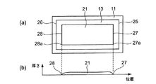
ところで、塗布機構15の各接着剤供給機構16の内部に設けられている弁が閉じられ、塗布ダイヘッド17への接着剤30の供給が遮断された後も、一定時間の間、定盤11は塗布機構15に対して移動速度V2で移動される。このため、図9に示すように、接着剤層21の終端28において、接着剤層21の厚さが他の部分と比べて厚くなることはない。また、定盤11が停止されるときには(時間=T4)、接着剤層21の終端28は塗布機構15から十分離れた位置にある。従って、定盤11が停止されるときに、塗布機構15の塗布ダイヘッド17に基材13上に塗布された接着剤が付着して、塗布ダイヘッド17の表面が汚染されることはない。このことにより、基材13上に厚みの均一な接着剤層21を形成するとともに、塗布ダイヘッド17の表面を清潔な状態に保つことができる。
By the way, after the valve provided in each
このように本実施の形態によれば、基材13上に接着剤30が塗布される場合、基材13のうち接着剤層21の終端28に対応する塗布領域終端28aが塗布機構15に達し、塗布機構15による接着剤30の塗布が停止された後も、塗布機構15に対して定盤11の移動を続ける。このため、接着剤層21の終端28において、接着剤層21の厚さが他の部分と比べて厚くなることはなく、また、定盤11が停止されるときには(時間=T4)、接着剤層21の終端28は塗布機構15から十分離れた位置にある。従って、定盤11が停止されるときに、塗布機構15の塗布ダイヘッド17に基材13上に塗布された接着剤が付着して、塗布ダイヘッド17の表面が汚染されることはない。このことにより、基材13上に厚みの均一な接着剤層21を形成するとともに、塗布ダイヘッド17の表面を清潔な状態に保つことができる。
As described above, according to the present embodiment, when the adhesive 30 is applied on the
第3の実施の形態
次に、図10および図11を参照して、本発明の第3の実施の形態について説明する。ここで、図10は、本発明の第3の実施の形態における接着剤塗布方法を示す図であり、図11は、本発明の第3の実施の形態において、基材上に形成された接着剤層の厚さを示す図である。
Third Embodiment Next, a third embodiment of the present invention will be described with reference to FIGS. Here, FIG. 10 is a diagram showing an adhesive application method according to the third embodiment of the present invention, and FIG. 11 is a diagram showing an adhesion formed on a substrate in the third embodiment of the present invention. It is a figure which shows the thickness of an agent layer.
図10および図11に示す第3の実施の形態は、定盤11の移動速度が異なるのみであり、他の構成は、図1乃至図7に示す第1の実施の形態と略同一である。図10および図11に示す第3の実施の形態において、図1乃至図7に示す第1の実施の形態と同一部分には同一符号を付して詳細な説明は省略する。
The third embodiment shown in FIGS. 10 and 11 differs only in the moving speed of the
塗布機構15が接着剤30を吐出するタイミングと定盤11の移動速度は、図10に示す接着剤塗布方法に従って制御される。この場合、まず定盤11は、基材13のうち接着剤層21の始端27に対応する塗布領域始端27aが塗布機構15よりも後方に位置するように配置される。次に、定盤11を、塗布機構15の配置方向に直交する方向において、前方に向って、移動速度がV1になるよう移動させる(時間=T1)。その後、基材13のうち接着剤層21の始端27に対応する塗布領域始端27aが塗布機構15の直下に到達したとき、定盤11を速度V1で移動させた状態で、塗布機構15の各接着剤供給機構16の内部に設けられている弁が開かれ、これによって、塗布ダイヘッド17へ接着剤30が供給される(時間=T2)。供給された接着剤30は塗布ダイヘッド17の開口部17aから吐出され、この結果、定盤11が塗布機構15に対して速度V1で移動する間、基材13上に接着剤30が均一に塗布される。
The timing at which the
その後、基材13のうち接着剤層21の終端28に対応する塗布領域終端28aが塗布機構15の直下に到達すると、塗布機構15の各接着剤供給機構16の内部に設けられている弁が閉じられ、塗布ダイヘッド17への接着剤30の供給が遮断される。同時に、制御装置50により定盤11の移動速度がV1からV2に減速される(時間=T3)。
Thereafter, when the application region end 28 a corresponding to the
定盤11の移動速度がV1からV2に減速されてから、一定期間の経過後、制御装置50により定盤11の移動が停止される(時間=T4)。次に、基材13上に塗布された接着剤30が固化されるよう、接着剤30が定盤11に設けられている冷却機構12により冷却され、これによって、基材13上に接着剤層21が形成される。
After the movement speed of the
ところで、基材13上に接着剤30を塗布する際、上述のとおり、塗布機構15に対して予め定盤11を移動速度V1で移動させて、その後、基材13のうち接着剤層21の始端27に対応する塗布領域始端27aが塗布機構15の直下に到達したとき、定盤11を速度V1で移動させた状態で、接着剤30が塗布ダイヘッド17の開口部17aから吐出される。このため、図11に示すように、接着剤層21の始端27において、接着剤層21の厚さが他の部分と比べて厚くなることはない。このことにより、基材13上に、厚みの均一な接着剤層21を形成することができる。
By the way, when applying the adhesive 30 on the
また、塗布機構15の各接着剤供給機構16の内部に設けられている弁が閉じられ、塗布ダイヘッド17への接着剤30の供給が遮断された後も、一定期間の間、定盤11は塗布機構15に対して移動速度V2で移動される。このため、図11に示すように、接着剤層21の終端28において、接着剤層21の厚さが他の部分と比べて厚くなることはない。また、定盤11が停止されるときには(時間=T4)、接着剤層21の終端28は塗布機構15から十分離れた位置にある。従って、定盤11が停止されるときに、塗布機構15の塗布ダイヘッド17に基材13上に塗布された接着剤が付着して、塗布ダイヘッド17の表面が汚染されることはない。このことにより、基材13上に厚みの均一な接着剤層21を形成するとともに、塗布ダイヘッド17の表面を清潔な状態に保つことができる。
Further, after the valves provided in the
このように本実施の形態によれば、基材13上に接着剤30が塗布される場合、塗布機構15に対して予め定盤11を移動させて、その後、基材13のうち接着剤層21の始端27に対応する塗布領域始端27aが塗布機構15に達した際、定盤11を速度V1で移動させた状態で、塗布機構15により接着剤30の塗布が開始される。このため、接着剤層21の始端27において、接着剤層21の厚さが他の部分と比べて厚くなることはない。このことにより、基材13上に、厚みの均一な接着剤層21を形成することができる。
As described above, according to the present embodiment, when the adhesive 30 is applied on the
また本実施の形態によれば、基材13上に接着剤30が塗布される場合、基材13のうち接着剤層21の終端28に対応する塗布領域終端28aが塗布機構15に達した際、塗布機構15による接着剤30の塗布が停止された後も、塗布機構15に対して定盤11の移動を続ける。このため、接着剤層21の終端28において、接着剤層21の厚さが他の部分と比べて厚くなることはなく、また、定盤11が停止されるときには(時間=T4)、接着剤層21の終端28は塗布機構15から十分離れた位置にある。従って、定盤11が停止されるときに、塗布機構15の塗布ダイヘッド17に基材13上に塗布された接着剤が付着して、塗布ダイヘッド17の表面が汚染されることはない。このことにより、基材13上に厚みの均一な接着剤層21を形成するとともに、塗布ダイヘッド17の表面を清潔な状態に保つことができる。
Further, according to the present embodiment, when the adhesive 30 is applied on the
10 接着剤塗布装置
11 定盤
12 冷却機構
12a 冷媒循環装置
12b ホース
12c 冷媒流路
13 基材
14a 搬送台
14b レール
14c ピストンロッド
15 塗布機構
16 接着剤供給機構
17 塗布ダイヘッド
17a 塗布ダイヘッドの開口部
18 接着剤タンク
19 ホース
21 接着剤層
22 基板
25 基材の前端
26 基材の後端
27 始端
27a 塗布領域始端
28 終端
28b 塗布領域終端
30 接着剤
31 非接触ICカード
32 インレット用基材
33 アンテナ
34 ICチップ
35 インレットシート
50 制御装置
DESCRIPTION OF
Claims (8)
基材が配置された定盤を、基材の幅方向に延びるよう配置された塗布機構に対して塗布機構の配置方向に直交する方向に相対移動させて、塗布機構により基材上に接着剤を塗布する工程と、
基材上に塗布された接着剤が固化されるよう、接着剤を定盤の冷却機構により冷却する工程と、を備えたことを特徴とする接着剤塗布方法。 Arranging the base material on a surface plate provided with a cooling mechanism;
The surface plate on which the base material is arranged is moved relative to the coating mechanism arranged so as to extend in the width direction of the base material in a direction perpendicular to the direction in which the coating mechanism is arranged, and the coating mechanism causes the adhesive on the base material A step of applying
And a step of cooling the adhesive by a cooling mechanism of a surface plate so that the adhesive applied on the substrate is solidified.
定盤上方に設けられ、基材の幅方向に延びるよう配置され、基材に接着剤を塗布する塗布機構と、
定盤に設けられ、基材上に塗布された接着剤を固化させる冷却機構と、を備え、
定盤は、塗布機構に対して塗布機構の配置方向に直交する方向に相対移動可能となることを特徴とする接着剤塗布装置。 A surface plate on which the base material is disposed;
An application mechanism that is provided above the surface plate and arranged to extend in the width direction of the base material, and applies an adhesive to the base material;
A cooling mechanism provided on the surface plate and solidifying the adhesive applied on the substrate,
An adhesive coating apparatus, wherein the surface plate is movable relative to the coating mechanism in a direction orthogonal to the direction of arrangement of the coating mechanism.
Priority Applications (1)
| Application Number | Priority Date | Filing Date | Title |
|---|---|---|---|
| JP2008205493A JP5196308B2 (en) | 2008-08-08 | 2008-08-08 | Adhesive application method and adhesive application device |
Applications Claiming Priority (1)
| Application Number | Priority Date | Filing Date | Title |
|---|---|---|---|
| JP2008205493A JP5196308B2 (en) | 2008-08-08 | 2008-08-08 | Adhesive application method and adhesive application device |
Publications (2)
| Publication Number | Publication Date |
|---|---|
| JP2010036171A true JP2010036171A (en) | 2010-02-18 |
| JP5196308B2 JP5196308B2 (en) | 2013-05-15 |
Family
ID=42009258
Family Applications (1)
| Application Number | Title | Priority Date | Filing Date |
|---|---|---|---|
| JP2008205493A Expired - Fee Related JP5196308B2 (en) | 2008-08-08 | 2008-08-08 | Adhesive application method and adhesive application device |
Country Status (1)
| Country | Link |
|---|---|
| JP (1) | JP5196308B2 (en) |
Cited By (1)
| Publication number | Priority date | Publication date | Assignee | Title |
|---|---|---|---|---|
| KR101755415B1 (en) * | 2017-01-03 | 2017-07-10 | (주)원텍 | Apparatus for spreading grease and method thereof |
Citations (7)
| Publication number | Priority date | Publication date | Assignee | Title |
|---|---|---|---|---|
| JPS59115467U (en) * | 1983-11-22 | 1984-08-04 | 花王株式会社 | coating equipment |
| JPS59115437U (en) * | 1983-01-20 | 1984-08-04 | みのる産業株式会社 | Household circulation type stone removal rice polishing machine |
| JPH04141271A (en) * | 1990-09-28 | 1992-05-14 | Kanebo Nsc Ltd | Coating device for hot melt, etc. |
| JP2002086044A (en) * | 2000-09-19 | 2002-03-26 | Toray Ind Inc | Coating method and coating tool, and manufacturing method and equipment for display member and plasma display |
| JP2003236432A (en) * | 2002-02-12 | 2003-08-26 | Konica Corp | Method for manufacturing laminate, method for coating adhesive, device for manufacturing laminate and device for coating adhesive |
| JP2005324385A (en) * | 2004-05-13 | 2005-11-24 | Dainippon Printing Co Ltd | Book cooling device and method |
| JP2008114225A (en) * | 2006-11-01 | 2008-05-22 | Palo Alto Research Center Inc | Extrusion head with leveled marginal surface |
-
2008
- 2008-08-08 JP JP2008205493A patent/JP5196308B2/en not_active Expired - Fee Related
Patent Citations (7)
| Publication number | Priority date | Publication date | Assignee | Title |
|---|---|---|---|---|
| JPS59115437U (en) * | 1983-01-20 | 1984-08-04 | みのる産業株式会社 | Household circulation type stone removal rice polishing machine |
| JPS59115467U (en) * | 1983-11-22 | 1984-08-04 | 花王株式会社 | coating equipment |
| JPH04141271A (en) * | 1990-09-28 | 1992-05-14 | Kanebo Nsc Ltd | Coating device for hot melt, etc. |
| JP2002086044A (en) * | 2000-09-19 | 2002-03-26 | Toray Ind Inc | Coating method and coating tool, and manufacturing method and equipment for display member and plasma display |
| JP2003236432A (en) * | 2002-02-12 | 2003-08-26 | Konica Corp | Method for manufacturing laminate, method for coating adhesive, device for manufacturing laminate and device for coating adhesive |
| JP2005324385A (en) * | 2004-05-13 | 2005-11-24 | Dainippon Printing Co Ltd | Book cooling device and method |
| JP2008114225A (en) * | 2006-11-01 | 2008-05-22 | Palo Alto Research Center Inc | Extrusion head with leveled marginal surface |
Cited By (1)
| Publication number | Priority date | Publication date | Assignee | Title |
|---|---|---|---|---|
| KR101755415B1 (en) * | 2017-01-03 | 2017-07-10 | (주)원텍 | Apparatus for spreading grease and method thereof |
Also Published As
| Publication number | Publication date |
|---|---|
| JP5196308B2 (en) | 2013-05-15 |
Similar Documents
| Publication | Publication Date | Title |
|---|---|---|
| US20080310938A1 (en) | Apparatus for Producing Ic Chip Package | |
| CN107336523A (en) | Variable information digital spraying print equipment and jet printing method | |
| US10118373B2 (en) | Apparatus for manufacturing double-layer fabric for down products having pattern joining line formed by high-frequency bonding | |
| KR101309275B1 (en) | Device and Method of Coating Both Sides of Film, and Coating Apparatus Having the Same | |
| US20130139949A1 (en) | Method for adhering works and work adhering apparatus | |
| JP5196308B2 (en) | Adhesive application method and adhesive application device | |
| JP2009298108A (en) | Method for manufacturing inkjet recording head, and inkjet recording head | |
| JP2010105389A (en) | Recording device | |
| JP4664960B2 (en) | Label sheet making device | |
| US8900657B2 (en) | Transferring medium manufacturing method and transferring medium | |
| US7076867B2 (en) | Pressurizing method | |
| JP2005064418A (en) | Direct-acting mechanism of electronic part mounting device | |
| KR100575559B1 (en) | Coverlay attach system | |
| JP2006309541A (en) | Manufacturing equipment for ic chip mounting body | |
| WO2013149116A1 (en) | In-mold labeling | |
| JP2015157385A (en) | Printer and printing method | |
| CN115214240A (en) | Ink jet printer for manufacturing display | |
| KR102589497B1 (en) | Uniform print head surface coating | |
| JP2013247326A (en) | Lamination device and method of forming insulation layer | |
| JP4101840B2 (en) | Card manufacturing method and card manufacturing apparatus | |
| KR101934239B1 (en) | Thin film coating device for glossy | |
| CN115214251B (en) | Ink-jet printing method and ink-jet printing device | |
| JP2011083746A (en) | Coating device and coating method | |
| US8562782B2 (en) | Method and device for interleaving a module or chip | |
| US9498981B2 (en) | Printed material processing method, printed material processing apparatus, and image forming apparatus |
Legal Events
| Date | Code | Title | Description |
|---|---|---|---|
| A621 | Written request for application examination |
Free format text: JAPANESE INTERMEDIATE CODE: A621 Effective date: 20110623 |
|
| A977 | Report on retrieval |
Free format text: JAPANESE INTERMEDIATE CODE: A971007 Effective date: 20120626 |
|
| A131 | Notification of reasons for refusal |
Free format text: JAPANESE INTERMEDIATE CODE: A131 Effective date: 20120629 |
|
| A521 | Written amendment |
Free format text: JAPANESE INTERMEDIATE CODE: A523 Effective date: 20120823 |
|
| TRDD | Decision of grant or rejection written | ||
| A01 | Written decision to grant a patent or to grant a registration (utility model) |
Free format text: JAPANESE INTERMEDIATE CODE: A01 Effective date: 20130111 |
|
| A61 | First payment of annual fees (during grant procedure) |
Free format text: JAPANESE INTERMEDIATE CODE: A61 Effective date: 20130124 |
|
| FPAY | Renewal fee payment (event date is renewal date of database) |
Free format text: PAYMENT UNTIL: 20160215 Year of fee payment: 3 |
|
| R150 | Certificate of patent or registration of utility model |
Ref document number: 5196308 Country of ref document: JP Free format text: JAPANESE INTERMEDIATE CODE: R150 Free format text: JAPANESE INTERMEDIATE CODE: R150 |
|
| LAPS | Cancellation because of no payment of annual fees |