JP2010035717A - Component on game machine board - Google Patents
Component on game machine board Download PDFInfo
- Publication number
- JP2010035717A JP2010035717A JP2008200093A JP2008200093A JP2010035717A JP 2010035717 A JP2010035717 A JP 2010035717A JP 2008200093 A JP2008200093 A JP 2008200093A JP 2008200093 A JP2008200093 A JP 2008200093A JP 2010035717 A JP2010035717 A JP 2010035717A
- Authority
- JP
- Japan
- Prior art keywords
- stage
- game
- game ball
- entrance
- ball
- Prior art date
- Legal status (The legal status is an assumption and is not a legal conclusion. Google has not performed a legal analysis and makes no representation as to the accuracy of the status listed.)
- Granted
Links
Images


Abstract
Description
本発明は、センター役物に設けたステージ上に配置した中空回転部材を回転動作させることによって遊技進行上特徴的な演出効果を発揮させることができるようにした遊技機に関する。 The present invention relates to a gaming machine capable of exhibiting a characteristic effect in the progress of a game by rotating a hollow rotating member disposed on a stage provided in a center accessory.
パチンコ遊技機等の遊技球を使用した遊技機においては、遊技盤の盤面に入賞口、風車、センター役物、画像表示装置、電飾装置等の各種盤面部品を設けて遊技内容の多様性を図り、遊技の進行中における入賞、その他の状況変化を契機として可動盤面部品を種々動作させることにより演出効果を高めている。
例えば、遊技盤面に設けられた始動入賞口に遊技球が入賞すると、遊技盤中の画像表示装置に表示される図柄が変動を開始し、所定時間経過後に停止した図柄が予め定めた大当たり図柄となった場合に大当たり状態となり、遊技者が大量の出球を獲得できるようになっている。
また、始動入賞口への入賞パターンに変化をもたらして興趣を高めるために、始動入賞口の直上位置に設けたステージ上において遊技球を滞留、揺動させてから下方へ流下させる構成を備えた遊技機が種々知られている。
更に、ステージ上に流入した遊技球の動作に変化を付与して始動入賞口への入賞パターン、外れパターンを多様化するために、特許文献1には、ステージに設けた凹部内に横軸線回りに回転する横長の回転体を配置し、回転体の表面に形成した溝状の横経路に沿って遊技球を移動させて複数の放出経路から放出するようにした遊技機が開示されている。
しかし、この装置構成では、回転体上の横経路内に沿って軸方向へ移動する遊技球の動作は比較的単純となるため、始動入賞口への入賞パターンも単純化し、飽きられやすい傾向にある。
In game machines using game balls such as pachinko machines, various board parts such as a prize opening, a windmill, a center object, an image display device, and an electrical decoration device are provided on the board surface of the game board to increase the variety of game contents. The effect of the stage is enhanced by operating the movable surface parts in various ways triggered by winnings during the game and other situations.
For example, when a game ball wins a start winning opening provided on the game board surface, the symbol displayed on the image display device in the game board starts to change, and the symbol stopped after a predetermined time has passed is a predetermined jackpot symbol. When it becomes, it becomes a big hit state, and a player can acquire a lot of balls.
In addition, in order to bring a change to the winning pattern at the start winning opening and to enhance the interest, it has a configuration in which the game ball stays and swings on the stage provided immediately above the starting winning opening and then flows downward. Various gaming machines are known.
Furthermore, in order to diversify the winning pattern and the disengagement pattern to the start winning opening by giving a change to the operation of the game ball that has flowed onto the stage, Patent Document 1 discloses a horizontal axis line in the recess provided on the stage. There is disclosed a gaming machine in which a horizontally long rotating body is disposed on the surface of the rotating body, and a game ball is moved along a groove-like horizontal path formed on the surface of the rotating body to be discharged from a plurality of discharge paths.
However, in this device configuration, the operation of the game ball moving in the axial direction along the horizontal path on the rotating body becomes relatively simple, so the winning pattern at the start winning opening is also simplified and tends to get tired. is there.
次に、特許文献2には、ステージに設けた凹部内に横軸線回りに往復回動(揺動)する往復回動部材を配置し、往復回動部材の外面に軸方向位置及び周方向位置を異ならせて複数の凹部(受容部)を設け、一つの凹部内に遊技球が入るとその自重によって往復回動部材が所要角度回動して該凹部から遊技球が排出されるようにした遊技機が開示されている。
しかし、遊技球が入った凹部から排出される単純な動作に過ぎないため、遊技球の排出経路のパターンが単純で予測し易くなり、意外性に乏しく、飽きられやすい傾向にある。
また、特許文献3、4にはステージ内に、横軸によって前後方向へ回転自在に軸支された回転役物を設け、この回転役物に装備した磁石によって遊技球を吸着してから下方へ放出したり、遊技球をステージに戻すようにした遊技機が開示されている。
ところで遊技者の最大の関心は、画像表示装置が変動して停止した結果が大当たりとなるか否かにあるので、画像表示装置の図柄変動開始の契機となる始動入賞口に遊技球が入球するか否かは、遊技者の興味を大いに引くところである。
しかし、いずれの特許文献にあっても、回転役物にて吸着または振り分けられた遊技球の挙動の変化が乏しく、容易に予測出来てしまうので、遊技者の興趣を高めるものとはならず、すぐに飽きられやすい傾向にあった。
However, since it is merely a simple operation of being discharged from the recess containing the game ball, the pattern of the discharge path of the game ball is simple and easy to predict, and there is a tendency that it is scarce and unexpected.
Further, in Patent Documents 3 and 4, a rotating accessory is provided in the stage so as to be rotatably supported in the front-rear direction by a horizontal axis, and a game ball is attracted by a magnet mounted on the rotating accessory and then moved downward. A gaming machine is disclosed that releases or returns a game ball to the stage.
By the way, the player's greatest interest is whether or not the result of the image display device fluctuating and stopping is a big hit, so that the game ball enters the start winning opening that triggers the start of symbol variation of the image display device. Whether or not to do so will greatly attract the player's interest.
However, in any patent document, the change in the behavior of the game ball that is attracted or distributed by the rotating object is scarce and can be easily predicted, so it does not enhance the interest of the player, There was a tendency to get bored quickly.
従来、遊技盤面に設けられるステージ上に前後方向へ回転する回転部材を設け、回転部材の外周面に設けた溝や凹部、或いは磁石により遊技球の移動方向に変化を持たせることにより興趣を高めるようにした遊技機が提案されているが、いずれも遊技球の動作、移動経路の変化パターンが単純で予測し易いため、飽きられやすかった。
本発明は上記に鑑みてなされたものであり、センター役物に設けたステージ上に配置した回転部材を回転動作させることにより遊技球の放出経路を変化させる際に、遊技球の排出位置を予測困難性化することにより、遊技進行上特徴的な演出効果を発揮させるようにした遊技機の盤面部品を提供することを目的としている。
Conventionally, a rotating member that rotates in the front-rear direction is provided on a stage provided on the surface of the game board, and a change is made in the moving direction of the game ball by a groove, a recess, or a magnet provided on the outer peripheral surface of the rotating member. Although such gaming machines have been proposed, all of them were easily bored because the operation of the game ball and the change pattern of the movement route were simple and easy to predict.
The present invention has been made in view of the above, and predicts the discharge position of the game ball when changing the discharge path of the game ball by rotating the rotating member arranged on the stage provided in the center accessory. It is an object of the present invention to provide a board part for a gaming machine that is made difficult to exhibit a characteristic effect in the progress of the game.
上記目的を達成するため、請求項1の発明に係る遊技機の盤面部品は、遊技盤面の略中央に配置された画像表示装置と、前記画像表示装置の外周に沿って配置され、遊技球が転動可能なステージを下部に有するセンター役物と、該ステージ下方の遊技盤面上に配置され入賞を条件に前記画像表示装置による変動表示を開始させる契機となる始動入賞口と、を備えた遊技機において、前記ステージは、前記センター役物内に進入してきた遊技球を受ける奥ステージと、該奥ステージの前方下方に配置された手前ステージと、を備え、前記奥ステージと前記手前ステージとの中間位置には、前記ステージの左右方向へ延びる回転軸を中心として一方向、又は正逆両方向へ回転自在に支持された中空回転部材が配置され、該中空回転部材の外壁には遊技球の導入、及び排出用の入出球穴が複数形成され、前記入出球穴の少なくとも一つは、該入出球穴から排出した遊技球が前記始動入賞口に向けて転動するように配置されていることを特徴とする。
ステージ上に落下した遊技球が手前側に転動して始動入賞口に入球することにより遊技者に有利な状況が出現するが、ステージ上からの遊技球の移動方向を予測不能、或いは予測困難とすることにより興趣を高めることができる。つまり、中空回転部材による遊技球の振り分けの結果が遊技の結果に影響を及ぼすものである。本発明では、奥ステージ上の遊技球を中空内部に導いて攪拌することにより遊技球の排出位置をランダム化することができる中空回転部材を装備している。特に、中空回転部材の外壁に軸方向位置を異ならせた入出球穴を複数設けて、入球位置と排出位置との対応関係を多様にばらつかせるようにしている。
In order to achieve the above object, a board component of a gaming machine according to the invention of claim 1 is arranged along the outer periphery of the image display device arranged at the approximate center of the game board surface, and the game ball is A game having a center role having a rollable stage at the bottom, and a start winning opening that is arranged on a game board surface below the stage and that triggers a variable display by the image display device on the condition of winning. In the machine, the stage includes a back stage that receives a game ball that has entered the center accessory, and a front stage disposed in front of and below the back stage, and the back stage and the front stage A hollow rotating member supported so as to be rotatable in one direction or both forward and reverse directions with a rotation axis extending in the left-right direction of the stage as a center is disposed at the intermediate position, and on the outer wall of the hollow rotating member A plurality of entrance / exit ball holes for introducing and discharging a game ball are formed, and at least one of the entrance / exit ball holes is configured such that the game ball discharged from the entrance / exit ball hole rolls toward the start winning opening. It is arranged.
The game ball that has fallen on the stage rolls to the near side and enters the starting prize opening, and a situation advantageous to the player appears, but the direction of movement of the game ball from the stage cannot be predicted or predicted Interest can be enhanced by making it difficult. That is, the result of the game ball distribution by the hollow rotating member affects the game result. The present invention is equipped with a hollow rotating member that can randomize the discharge position of the game ball by guiding the game ball on the back stage into the hollow interior and stirring it. In particular, a plurality of entrance / exit ball holes having different axial positions are provided on the outer wall of the hollow rotating member so that the correspondence between the entrance position and the discharge position can be varied.
請求項2の発明は、請求項1において、前記中空回転部材は、樽形、鼓形、筒形、或いは錐形であることを特徴とする。
中空回転部材は、内部に導入した一つ又は複数個の遊技球を内部で転動させたり弾ませることにより、軸方向移動させることができる構成であれば、どのようなものであってもよい。
請求項3の発明は、請求項1又は2において、前記中空回転部材の軸方向端面に遊技球の導入、及び排出用の入出球穴を設けたことを特徴とする。
中空回転部材の外周面のみならず、軸方向端面にも入出球穴を設けることにより入球位置、排出位置に多様性をもたせることができる。
請求項4の発明は、請求項1乃至3の何れか一項において、前記中空回転部材の内壁に、前記入出球穴から内部に入球した遊技球を攪拌するためのリブ、或いは突起を設けたことを特徴とする。
中空回転部材の内面が平坦面である場合には、遊技球の挙動が安定し、入球位置と排出位置との関係が特定化する虞がある。そのような不具合を解消するには、内壁に遊技球の動作を種々変化させるためのリブ、突起を設けて攪拌し、多様な方向に転動、ジャンプさせることが有効である。
請求項5の発明は、請求項1乃至4の何れか一項において、前記中空回転部材の内壁には、前記入出球穴に向けて陥没する凹所が設けられていることを特徴とする。
中空回転部材の内部において転動する遊技球を確実に入出球穴に導いて外部に排出することが可能となる。
A second aspect of the present invention is characterized in that, in the first aspect, the hollow rotating member has a barrel shape, a drum shape, a cylindrical shape, or a cone shape.
The hollow rotating member may be of any configuration as long as it can move in the axial direction by rolling or bounce one or more game balls introduced therein. .
According to a third aspect of the present invention, in the first or second aspect of the present invention, an introduction ball hole for introducing and discharging game balls is provided on an axial end surface of the hollow rotating member.
By providing entrance / exit ball holes not only on the outer peripheral surface of the hollow rotary member but also on the end surface in the axial direction, it is possible to give diversity to the entrance position and the exit position.
According to a fourth aspect of the present invention, in any one of the first to third aspects, a rib or a protrusion for stirring the game ball that has entered the inside through the entrance / exit ball hole is provided on the inner wall of the hollow rotary member. It is provided.
When the inner surface of the hollow rotating member is a flat surface, the behavior of the game ball is stabilized, and the relationship between the entrance position and the discharge position may be specified. In order to solve such a problem, it is effective to provide ribs and protrusions on the inner wall for variously changing the operation of the game ball and to stir and roll and jump in various directions.
According to a fifth aspect of the present invention, in any one of the first to fourth aspects, the inner wall of the hollow rotary member is provided with a recess that is recessed toward the entrance / exit ball hole. .
The game ball that rolls inside the hollow rotating member can be reliably guided to the entrance / exit ball hole and discharged to the outside.
以上のように本発明によれば、センター役物に設けたステージ上に配置した中空回転部材内に遊技球を導いて攪拌し、軸方向位置の異なる他の入出球穴から排出させ得るように構成したので、遊技球の排出経路を多様に変化させて遊技球の排出位置が容易に予測されてしまう事態の発生を防止でき、遊技球の挙動に対する遊技者の興趣を高めることができるので、遊技進行上特徴的な演出効果を発揮することができる。 As described above, according to the present invention, the game ball can be guided and stirred in the hollow rotating member arranged on the stage provided in the center accessory so that it can be discharged from other entrance and exit ball holes having different axial positions. Since it is configured, it is possible to prevent the occurrence of a situation where the discharge position of the game ball is easily predicted by changing the discharge path of the game ball in various ways, and the player's interest in the behavior of the game ball can be enhanced, It is possible to exert a characteristic effect in the progress of the game.
以下、本発明を図面に示した実施の形態により詳細に説明する。
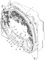
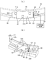
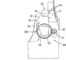
図1は本発明に係る盤面部品を備えたパチンコ遊技機の遊技盤の一例を示す正面図であり、図2は遊技盤の斜視図であり、図3はセンター役物を除去した本発明の盤面部品の概略構成を示す正面図であり、図4(a)及び(b)は本発明の一実施形態に係る盤面部品に装備される中空回転部材の構成を示す正面図、及び斜視図であり、図5は中空回転部材の駆動機構の説明図である。
図1、図2に示すパチンコ遊技機1は、図示しない矩形形状の枠の窓孔に対して裏側から装着される遊技盤2を備えている。
遊技盤2には、遊技領域の外周縁に沿って前方に突出されたガイドレールが設けられている。ガイドレールは発射装置から発射された遊技球を遊技領域の上部に案内したり、アウト球を回収するアウト口13に案内したりする外レールR1及び内レールR2により構成される。
遊技盤2の前面側には、図示しないガラス枠が開閉可能に取り付けられている。また遊技盤2の下部には遊技球を貯留する図示しない受け皿部と、受け皿部内の遊技球を発射する図示しない発射レバー等が設けられている。また、受け皿部の上部には、例えば遊技演出用のチャンスボタンや十字キーなどの操作部や、遊技球の購入ボタンや購入取り消しボタンなどが設けられている。
Hereinafter, the present invention will be described in detail with reference to embodiments shown in the drawings.
FIG. 1 is a front view showing an example of a game board of a pachinko gaming machine having board parts according to the present invention, FIG. 2 is a perspective view of the game board, and FIG. It is a front view which shows schematic structure of a board surface component, FIG. 4 (a) and (b) is a front view which shows the structure of the hollow rotation member with which the board surface component which concerns on one Embodiment of this invention is equipped, and a perspective view. FIG. 5 is an explanatory diagram of a drive mechanism for the hollow rotating member.
A pachinko gaming machine 1 shown in FIGS. 1 and 2 includes a
The
A glass frame (not shown) is attached to the front side of the
遊技盤2の略中央に設けた開口部内には略環状のセンター役物3が配置され、センター役物3の内部開口内には画像表示装置5が配置されている。画像表示装置5は、例えば、液晶表示装置等の液晶表示パネルによって構成され、通常動作状態の時は図示しない特別図柄画像が表示される。また、所謂リーチ状態や特別遊技状態の時はそれぞれの遊技状態であることを示す演出画像等が表示される。
センター役物3の下縁部であって始動入賞口の直上位置にはステージ30が配置されている。センター役物3の左側には、ワープ入口14a及びワープ出口14bを備えたワープ通路14が設けられ、遊技盤面を流下する遊技球がワープ入口14aに入るとワープ出口14bを経てステージ30上に排出される。ステージ30の上面は遊技球が転動可能に構成されている。
ステージ30の直下位置に相当する盤面上には、画像表示装置5の特別図柄を可変表示させるための可変入賞装置6が設けられている。ステージ30から遊技球を遊技領域内に落下させることで、可変入賞装置6に入球し易くしたり、入球しそうな状態を頻繁に作り出すことができる。
A substantially ring-shaped center accessory 3 is disposed in an opening provided in the approximate center of the
A
A variable winning
また、画像表示装置5の左側には、遊技盤2の右下部に配置された普通図柄表示装置10に表示される普通図柄を作動させるためのゲート11が設けられている。
さらに、可変入賞装置6の下方には、特別遊技状態の一つである大当り状態のときに開成状態になる開閉扉を有する大入賞口7が設けられている。
可変入賞装置6は、画像表示装置5を可変表示させるための上始動ポケット(始動入賞口)6aと、左右一対の開閉爪(可動片)を有する電動式チューリップ6bとを備えている。
また遊技盤2には、普通入賞口8が設けられていると共に、風車9や多数の遊技釘12が突設されている。遊技釘12は、遊技球の落下速度を遅くすると共に、落下方向を複雑に変化させて遊技進行上の興趣を高めている。
普通図柄表示装置10に表示される普通図柄は、1個または複数個の図柄を変動表示可能であり、普通図柄始動口としてのゲート11が遊技球を検出することを条件に、その図柄が乱数制御等により所定時間可変して停止するようになっている。
Further, on the left side of the
Further, below the variable winning
The variable winning
Further, the
The normal symbol displayed on the normal
普通図柄としては、数字図柄、アルファベット図柄、キャラクター図柄、その他の適宜の遊技図柄が使用される。そして、ゲート11を遊技球が通過したことを条件に乱数制御により普通図柄が所定態様となった場合に、可変入賞装置6に設けられた電動式チューリップから成る可動片を所定時間、開成動作するように構成されている。
画像表示装置5に表示される特別図柄は、停止図柄が予め定められた図柄の組合せ、例えば同一図柄の組合せとなった場合に大当り状態となるように構成されている。また特別図柄は、可変入賞装置6の上始動ポケット6a、又は電動式チューリップ6bの開成動作により遊技球が誘導される下始動口(図示していない)への遊技球の入賞を検出することを条件に乱数制御等により表示がスクロールする等、所定の変動パターンで所定時間変動(可変)して図柄で停止するようになっている。その際、有効ライン上に2個の停止図柄が同一となった場合に、リーチ状態が発生し、このリーチ状態において、有効ライン上の最後の停止図柄が既に停止している2個の図柄と同一となった場合に大当り状態が発生する。なお、特別図柄としては、数字図柄、アルファベット図柄、キャラクター図柄等が使用可能である。
As a normal symbol, a numerical symbol, an alphabet symbol, a character symbol, and other appropriate game symbols are used. Then, when the normal symbol becomes a predetermined mode by random number control on the condition that the game ball has passed through the gate 11, the movable piece made of the electric tulip provided in the
The special symbol displayed on the
図2、図4等の斜視図から明らかなようにステージ30は、ワープ通路14を経てセンター役物3内に進入してきた遊技球を受ける奥ステージ31と、奥ステージの前方下方に段差状に配置された手前ステージ32と、を備えている。更に、奥ステージ31と手前ステージ32との中間位置には、ステージの左右方向へ延びる横軸41を回転中心として前方向F、又は後方向R、或いは前後両方向へ回転自在に支持(軸支)された中空回転部材40を配置し、中空回転部材40の外壁42には遊技球の導入、及び排出用の入出球穴43が複数形成されている。入出球穴43の少なくとも一つは、該入出球穴から排出した遊技球が始動入賞口に向けて転動するように配置されている。なお、外壁42は、中空回転部材40を構成する略筒状の板材から成り、樹脂、金属等から構成する。
本発明の特徴的な構成は、奥ステージ31上から手前ステージ32上に落下しようとする遊技球を自転する中空回転部材40の外面と一旦当接させてその移動経路を変化させるばかりでなく、遊技球が入出球穴43と整合する位置に達したときにこの入出球穴から中空回転部材40内部に進入してその内部で攪拌されることにより中空回転部材内で軸方向へランダムに移動されるようにした点にある。その結果、遊技球は入球した入出球穴43とは異った軸方向位置にある他の入出球穴43から手前ステージ32側へ排出される率が高くなり、排出位置を予測することが困難となる。
As is clear from the perspective views of FIGS. 2 and 4, the
The characteristic configuration of the present invention not only changes the movement path by bringing the game ball about to fall from the
横軸41は、実在する軸部材である必要はなく、中空回転部材40の外周面、或いは軸方向端部内周面を図示しない軸受部材によって軸支することにより架空の横軸に沿って前後方向(F方向、又はR方向)へ回転するように構成した場合を広く含むものである。
中空回転部材40を奥ステージ31と手前ステージ32の中間位置に設けた凹所30A内に配置すると共に、奥ステージ31上で遊動してから前方へ移動してくる遊技球が中空回転部材40の上部に位置する入出球穴に入球し易くなるように奥ステージ31との位置関係を適切に設定する。また、中空回転部材40内部の遊技球が下側に回転移動してきた入出球穴43から外部に排出される際に手前ステージ32上に移動し易いように手前ステージ32との位置関係を適切に設定する。
奥ステージ31の上面は前方から見て中央部が上方に膨出した円弧状をなすように構成するが、中央部と左右両端部には手前側に向けて遊技球が転動し易いように窪み、又は溝31aを設ける。中空回転部材40に設ける入出球穴43はこれらの窪み、又は溝31aと対応した位置に設けるのが好ましい。
The
The hollow rotating
The upper surface of the
手前ステージ32の上面は前方から見て全体的に円弧状に下向きに凹んでいるが、中空回転部材40の入出球穴43から排出されてきた遊技球が盤面側に転動、落下し易いように各入出球穴に対応する位置、少なくとも中央部に窪み、又は溝32aを設ける。
中空回転部材40の外壁42の外観形状としては、図示のように軸方向中央部が膨出した樽形の他に、中央部が凹んだ鼓形、寸胴状の筒形(円筒、多角筒等)等のドラム形状や、軸方向一端部の外径が他端の外径よりも小さい錐形(円錐、多角錐等)を例示することができる。或いは、球状体、立方体であってもよい。或いは、異なった形状の中空体を軸方向につなぎ合わせた構成であってもよい。要するに、前後方向に回転することにより入出球穴43から中空内部に遊技球を導入し、導入した後でランダムな方向へ排出し得るようにした構成であればよい。
中空回転部材40を鼓形状とすることにより、軸方向中央部に位置する入出球穴43から入球した遊技球を、中空回転部材の回転中に軸方向へ分散させることが容易となる。
中空回転部材40を多角筒形状とすることにより、その内壁に沿って転動する遊技球の動作を多様に変化させることが可能となる。
Although the upper surface of the
As the external shape of the
By making the
By making the hollow rotating
外壁42は、少なくともその一部を透明、或いは半透明材料(有色透明材料)から構成して内部の遊技球を視認できるように構成する。或いは、外壁42をメッシュ材料、或いは多数の小穴、スリットが形成されたパンチング材料から構成して内部を視認可能としてもよい。或いは、中空回転部材の側面側や背面側に電飾基板を配置し、適宜 発光させることにより中空回転部材内の遊技球の転動を確認しやすくしてもよい。
入出球穴43の形状、個数、配置箇所に制限はないが、少なくとも一個又は複数個の遊技球が入球し易く、排出され易い開口サイズを有することが必要であり、開口形状については円形、長円形、楕円形、長方形、正方形等、任意の形状を選択可能である。同じ軸方向位置の周方向に沿って所定のピッチにて複数個の入出球穴43を配置することにより、中空回転部材内部への入球率を高めることができる。また、軸方向位置を異ならせた複数箇所に入出球穴43を配置することにより、入球位置と排出位置が異なった軸方向位置となり、遊技球の排出位置の意外性、不定期性を得ることが可能となる。
また、個々の入出球穴43の開口サイズ、形状を一致させる必要はなく、特定の入出球穴43だけを入球、或いは排出球し易いように寸法、形状設定してもよい。
なお、入出球穴43は外壁42のみならず、中空回転部材40の軸方向端面に配置することにより、外壁に設けた入出球穴から入球した遊技球が軸方向端面側から排出されるようにして更に排出方向に多様性をもたしても構成してもよい。或いは、軸方向端面に設ける入出球穴から遊技球が入球可能に構成してもよい。或いは、外壁42と軸方向端面との境界線(角部)に沿って入出球穴を設けても良い。
The
There is no limitation on the shape, number, and location of the entrance /
Moreover, it is not necessary to match the opening size and shape of each entrance /
The entrance /
次に、図4、及び図5に基づいて中空回転部材の駆動機構の構成例について説明する。
駆動機構50は、実在する横軸41、或いは図示しない軸受部材によって、中空回転部材40を前後方向F、Rへ回転自在に軸支されると共に、モータ55によって前方向F、或いは/及び、後方向Rへ回転駆動されるように構成されている。本例では、モータ55の出力軸51aに設けた駆動ギヤ52を中空回転部材40の端部外周に設けた従動ギヤ53と噛合させることにより中空回転部材40に対して駆動力を伝達するように構成している。回転方向は、前方向Fとしてもよいし、後方向Rとしてもよいし、正逆両方向へ切替え自在としてもよい。或いは、図示しない軸方向移動機構を用いて中空回転部材40をその軸方向へ揺動させたり、軸方向へ進退、振動させるように構成してもよい。
中空回転部材40の回転速度は通常の遊技状態においては一定速度(例えば、毎分3〜6回転)であることが好ましいが、駆動制御手段55によるモータ制御により遊技の進行状況に応じて速度を変化(増速、減速)させたり、間欠駆動させるようにしてもよい。
Next, a configuration example of the drive mechanism for the hollow rotating member will be described with reference to FIGS. 4 and 5.
The
The rotation speed of the hollow rotating
次に、中空回転部材40が樽形状であると、入出球穴43から導入された遊技球が中空回転部材の回転に伴って軸方向中央部に集中して常に中央部の入出球穴から排出されて上始動ポケット6aに直行する虞があるため、図6(a)の断面図に示すように、中空回転部材の内壁に入出球穴から入った遊技球Bを軸方向に分散させるためのリブ(仕切部材)60を設けることが好ましい。
リブ60は、特定の入出球穴から中空回転部材40内に入った遊技球Bを軸方向位置が異なる他の入出球穴から排出され易いようにするために、図6(a)に示すように各入出球穴43の周方向への移動経路を塞ぐように設けると共に、軸方向への移動経路を開放しておく。このように構成すれば、中空回転部材40の回転による遠心力によって内壁に沿って転動する遊技球はリブ60によって軸方向へ移動するように促進されることとなる。特に、リブ60の内壁60aを図示のように鈍角状に構成したり曲面状に構成することにより、リブ60の内壁に突き当たった遊技球を軸方向へ移動させることが容易となる。また、リブ60の突出方向は、内壁に対して略直交する方向である必要はなく、任意の斜め方向に突出させてもよい。また、リブの長さ、形状、配置の粗密を種々異ならせることにより、遊技球をガイドする方向に変化をもたせて排出位置をばらつかせることができる。
Next, if the hollow rotating
As shown in FIG. 6A, the
なお、図6(b)の要部A−A断面図に示すように入出球穴43を設けた内壁面に、入出球穴43へ向けて落ち込む曲面状、或いはテーパー面状の凹面44を設けることにより、中空回転部材40の回転時の遠心力によって内壁に沿って転動する遊技球Bを安定して入出球穴43内に導くことができる。即ち、入出球穴43が手前側下方に移動してきて手前ステージ32の上面に遊技球を排出可能な位置に達した際に、凹面44が存在することにより凹面44と接する位置にある遊技球Bは遠心力により確実に当該入出球穴内に導かれて手前ステージ32上に排出される。
このため、中空回転部材内に入球した遊技球を確実に外部に排出することが可能となる。
或いは、図6(c)に示すように中空回転部材40の内壁面上に長さの異なる複数の突起61を規則的、或いは不規則的に配置することにより、中空回転部材の回転に伴って入球した遊技球が突起61に突き当たってランダムに弾んで種々の方向に移動してから入出球穴から排出されるように構成してもよい。突起61の突出方向は、内壁に対して略直交する方向である必要はなく、任意の斜め方向に突出させてもよい。突起の長さ、配置の粗密を種々異ならせることにより、遊技球の弾む方向に変化をもたせて排出位置をばらつかせることができる。
更に、中空回転部材40の外壁42の外面にリブ、突起を設けて奥ステージ31上から中空回転部材40上に移動してくる遊技球を入出球穴43に入球し易くしたり、或いは軸方向に分散させるようにしてもよい。
6B, a
For this reason, it is possible to reliably discharge the game ball that has entered the hollow rotating member to the outside.
Alternatively, as shown in FIG. 6C, a plurality of
Further, ribs and protrusions are provided on the outer surface of the
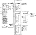
次に、図7は、遊技盤2の背面側に取り付けられた遊技機1の制御機構を示すブロック図である。遊技盤2の背面側には、遊技機1の主たる動作を制御する主制御基板100、と主制御基板100から出力される信号やコマンドに基づいて各部を制御するサブ制御基板と、が設けられている。図示した構成例の場合、サブ制御基板は、払出制御基板120、演出制御基板130、画像制御基板140、ランプ制御基板150等で構成されている。
主制御基板100は、CPU101とROM102とRAM103とを備えている。この主制御基板100には、始動入賞口6a及び電動チューリップ6bに入球したことを検出する始動入賞口スイッチ110、電動チューリップ6bを開閉させる始動入賞口ソレノイド111、遊技球がゲート11を通過したことを検知するゲートスイッチ112、大入賞口7に入球したことを検知する大入賞口スイッチ113、大入賞口7の開閉扉を開閉させる大入賞口ソレノイド114、および、普通入賞口8に入球したことを検知する普通入賞口スイッチ115が接続されている。
Next, FIG. 7 is a block diagram showing a control mechanism of the gaming machine 1 attached to the back side of the
The
主制御基板100は、始動口スイッチ110、大入賞口スイッチ113、及び普通入賞口スイッチ115のそれぞれに入球したことを検知した場合、払出制御基板120に対して払出司令信号を送出する。払出制御基板120は、CPU121とROM122とRAM123とを備え、遊技盤2の背面側に設けられた払出駆動モータ124を制御するように構成されており、主制御基板100から払出指令信号を入力すると、入球した入賞口に応じて所定球数の払い出しを行う。
また主制御基板100は各々の抽選を行うように構成されており、例えば遊技球がゲート11を通過した場合、電動チューリップ9bを開閉するための抽選を行い、当りならば始動入賞口ソレノイド111を所定時間、若しくは所定回数駆動させて電動チューリップを開放させる。また始動入賞口6aや開放時の電動チューリップ6bに入球したことを検知した場合には、大当り抽選が行われ、その大当り抽選結果に応じた演出を行わせるべく、演出制御基板130に対して信号やコマンドを送出する。
The
The
演出制御基板130は、CPU131とROM132とRAM133とを備えており、画像制御基板140とランプ制御基板150のそれぞれを制御する。画像制御基板140は、CPU141とROM142とRAM143とを備えており、演出制御基板130からの指示に基づいて画像表示装置においての変動表示を行うと共に、演出制御基板130から指定された図柄でその変動表示を停止させる。
このとき、例えば主制御基板100における大当りの抽選結果が大当たりであれば、画像表示装置における変動表示が所定の図柄で揃った状態で停止する。また画像制御基板140は、スピーカ144から演出用の効果音を発生させるように構成されている。ランプ制御部150は、CPU151とROM152とRAM153とを備えており、演出制御基板130からの指示に基づいて各種ランプ154を点灯させるように構成されている。尚、このような各種制御基板における処理フローとしては、既に公知となっている処理フローを採用することができる。
The
At this time, for example, if the big win lottery result on the
また本実施形態では、図4に示すように主制御基板100に対しモータ55が接続されており、電源投入時以降、主制御基板100が予め設定された駆動パターンに基づいてモータを駆動するように構成されている。この駆動パターンとしては、毎分3〜6回転程度の定速駆動、その他、遊技の進行状況に応じた変則的な駆動等々、任意の駆動パターンを選定することができる。
このように本発明の盤面部品にあっては、奥ステージから中空回転部材40に設けた何れかの入出球穴に入球した遊技球がどの入出球穴からも排出できるように構成されている。しかも、中空回転部材内部では、遊技球の移動方向を制限したり、一定方向へ導いたりするためのリブ、突起が設けられているので、入球した入出球穴と排出する入出球穴との関係が一定とはならず、遊技者にとって有利となったり不利となる状況がランダムに出現する。従って、中空回転部材内部に遊技球が入った場合には遊技者にとって排出位置、排出タイミングを予測することが困難となり、大きな興趣が得られる。
In the present embodiment, as shown in FIG. 4, a
As described above, the board component according to the present invention is configured such that a game ball that has entered the entrance / exit ball hole provided in the
中空回転部材は、内部に導入した一つ又は複数個の遊技球を内部で転動させたり弾ませることにより、軸方向移動させることができる構成であれば、どのようなものであってもよい。
中空回転部材の外周面のみならず、軸方向端面にも入出球穴を設けることにより入球位置、排出位置に多様性をもたせることができる。
中空回転部材の内面が平坦面である場合には、遊技球の挙動が安定し、入球位置と排出位置との関係が特定化する虞がある。そのような不具合を解消するには、内壁に遊技球の動作を種々変化させるためのリブ、突起を設けることが有効である。
入出球穴の周縁に相当する内壁に凹面を設けることにより、中空回転部材の内部において転動する遊技球を確実に入出球穴に導いて外部に排出することが可能となる。
上記の如き構成を備えた盤面部品は、パチンコ遊技機のみならず、遊技球を使用した他の遊技機一般にも適用することができる。
The hollow rotating member may be of any configuration as long as it can move in the axial direction by rolling or bounce one or more game balls introduced therein. .
By providing entrance / exit ball holes not only on the outer peripheral surface of the hollow rotary member but also on the end surface in the axial direction, it is possible to give diversity to the entrance position and the exit position.
When the inner surface of the hollow rotating member is a flat surface, the behavior of the game ball is stabilized, and the relationship between the entrance position and the discharge position may be specified. In order to solve such a problem, it is effective to provide ribs and protrusions on the inner wall for changing the operation of the game ball in various ways.
By providing a concave surface on the inner wall corresponding to the peripheral edge of the entrance / exit ball hole, it is possible to reliably guide the game ball rolling inside the hollow rotary member to the entrance / exit ball hole and discharge it to the outside.
The board component having the above-described configuration can be applied not only to pachinko gaming machines but also to other gaming machines in general using gaming balls.
1…パチンコ遊技機、2…遊技盤、3…センター役物、5…画像表示装置、6…可変入賞装置、6a…上始動ポケット、6b…電動式チューリップ、7…大入賞口、8…普通入賞口、9…風車、10…普通図柄表示装置、11…ゲート、12…遊技釘、13…アウト口、14…ワープ通路、14a…ワープ入口、14b…ワープ出口、30…ステージ、31…奥ステージ、31a…溝、32…手前ステージ、32a…溝、40…中空回転部材、41…横軸、42…外壁、43…入出球穴、44…凹面、50…駆動機構、51…モータ、55a…出力軸、52…駆動ギヤ、52…従動ギヤ、55…駆動制御手段、60…リブ、60a…内壁、61…突起、100…主制御基板、101…CPU、102…ROM、103…RAM、110…始動入賞口スイッチ、111…始動入賞口ソレノイド、112…ゲートスイッチ、113…大入賞口スイッチ、114…大入賞口ソレノイド、115…普通入賞口スイッチ、120…払出制御基板、121…CPU、122…ROM、123…RAM、124…払出モータ、130…演出制御基板、131…CPU、132…ROM、133…RAM、140…画像制御基板、141…CPU、142…ROM、143…RAM、144…スピーカ、150…ランプ制御基板、150…ランプ制御部、151…CPU、152…ROM、153…RAM、154…各種ランプ DESCRIPTION OF SYMBOLS 1 ... Pachinko machine, 2 ... Game board, 3 ... Center part, 5 ... Image display device, 6 ... Variable prize-winning device, 6a ... Upper start pocket, 6b ... Electric tulip, 7 ... Grand prize opening, 8 ... Normal Winning entrance, 9 ... Windmill, 10 ... Normal symbol display device, 11 ... Gate, 12 ... Game nail, 13 ... Out port, 14 ... Warp passage, 14a ... Warp entrance, 14b ... Warp exit, 30 ... Stage, 31 ... Back Stage, 31a ... groove, 32 ... front stage, 32a ... groove, 40 ... hollow rotating member, 41 ... horizontal axis, 42 ... outer wall, 43 ... entrance / exit ball hole, 44 ... concave surface, 50 ... drive mechanism, 51 ... motor, 55a DESCRIPTION OF SYMBOLS ... Output shaft, 52 ... Drive gear, 52 ... Drive gear, 55 ... Drive control means, 60 ... Rib, 60a ... Inner wall, 61 ... Projection, 100 ... Main control board, 101 ... CPU, 102 ... ROM, 103 ... RAM, 110 ... Start Prize opening switch, 111 ... Start winning opening solenoid, 112 ... Gate switch, 113 ... Large winning opening switch, 114 ... Large winning opening solenoid, 115 ... Normal winning opening switch, 120 ... Payout control board, 121 ... CPU, 122 ... ROM , 123 ... RAM, 124 ... dispensing motor, 130 ... production control board, 131 ... CPU, 132 ... ROM, 133 ... RAM, 140 ... image control board, 141 ... CPU, 142 ... ROM, 143 ... RAM, 144 ... speaker, 150 ... Lamp control board, 150 ... Lamp control unit, 151 ... CPU, 152 ... ROM, 153 ... RAM, 154 ... Various lamps
Claims (5)
前記ステージは、前記センター役物内に進入してきた遊技球を受ける奥ステージと、該奥ステージの前方下方に配置された手前ステージと、を備え、
前記奥ステージと前記手前ステージとの中間位置には、前記ステージの左右方向へ延びる回転軸を中心として一方向、又は正逆両方向へ回転自在に支持された中空回転部材が配置され、該中空回転部材の外壁には遊技球の導入、及び排出用の入出球穴が複数形成され、
前記入出球穴の少なくとも一つは、該入出球穴から排出した遊技球が前記始動入賞口に向けて転動するように配置されていることを特徴とする遊技機の盤面部品。 An image display device arranged substantially at the center of the game board surface, a center accessory arranged along the outer periphery of the image display device and having a stage on which a game ball can roll, and a game board surface below the stage In a gaming machine provided with a start winning opening that is an opportunity to start variable display by the image display device on the condition of winning
The stage includes a back stage that receives a game ball that has entered the center role, and a front stage disposed in front of the back stage,
A hollow rotating member is disposed at an intermediate position between the back stage and the front stage so as to be rotatable in one direction or both forward and reverse directions about a rotation axis extending in the left-right direction of the stage. In the outer wall of the member, a plurality of entrance and exit ball holes for introduction and discharge of game balls are formed,
At least one of the entry / exit ball holes is arranged such that a game ball discharged from the entry / exit ball hole rolls toward the start winning opening.
Priority Applications (1)
| Application Number | Priority Date | Filing Date | Title |
|---|---|---|---|
| JP2008200093A JP5548348B2 (en) | 2008-08-01 | 2008-08-01 | Game machine |
Applications Claiming Priority (1)
| Application Number | Priority Date | Filing Date | Title |
|---|---|---|---|
| JP2008200093A JP5548348B2 (en) | 2008-08-01 | 2008-08-01 | Game machine |
Publications (2)
| Publication Number | Publication Date |
|---|---|
| JP2010035717A true JP2010035717A (en) | 2010-02-18 |
| JP5548348B2 JP5548348B2 (en) | 2014-07-16 |
Family
ID=42008872
Family Applications (1)
| Application Number | Title | Priority Date | Filing Date |
|---|---|---|---|
| JP2008200093A Expired - Fee Related JP5548348B2 (en) | 2008-08-01 | 2008-08-01 | Game machine |
Country Status (1)
| Country | Link |
|---|---|
| JP (1) | JP5548348B2 (en) |
Cited By (12)
| Publication number | Priority date | Publication date | Assignee | Title |
|---|---|---|---|---|
| JP2012040345A (en) * | 2010-12-27 | 2012-03-01 | Fujishoji Co Ltd | Pinball game machine |
| JP2012045362A (en) * | 2011-01-17 | 2012-03-08 | Fujishoji Co Ltd | Pinball game machine |
| JP2013123607A (en) * | 2011-12-16 | 2013-06-24 | Fujishoji Co Ltd | Pinball game machine |
| JP2013123608A (en) * | 2011-12-16 | 2013-06-24 | Fujishoji Co Ltd | Pinball game machine |
| JP2015202118A (en) * | 2014-04-10 | 2015-11-16 | 株式会社三洋物産 | Game machine |
| JP2017064414A (en) * | 2016-09-30 | 2017-04-06 | 株式会社三洋物産 | Game machine |
| JP2017123949A (en) * | 2016-01-13 | 2017-07-20 | 株式会社三洋物産 | Game machine |
| JP2017123950A (en) * | 2016-01-13 | 2017-07-20 | 株式会社三洋物産 | Game machine |
| JP2018111033A (en) * | 2018-04-26 | 2018-07-19 | 株式会社三洋物産 | Game machine |
| JP2020121233A (en) * | 2020-05-25 | 2020-08-13 | 株式会社三洋物産 | Game machine |
| JP2020121232A (en) * | 2020-05-25 | 2020-08-13 | 株式会社三洋物産 | Game machine |
| JP2022111325A (en) * | 2017-03-22 | 2022-07-29 | 株式会社三洋物産 | game machine |
Citations (9)
| Publication number | Priority date | Publication date | Assignee | Title |
|---|---|---|---|---|
| JP2004073264A (en) * | 2002-08-09 | 2004-03-11 | Heiwa Corp | Central ornament of pachinko machine |
| JP2004097800A (en) * | 2002-07-17 | 2004-04-02 | Daiichi Shokai Co Ltd | Game machine |
| JP2004248933A (en) * | 2003-02-21 | 2004-09-09 | Sansei R & D:Kk | Pachinko game machine |
| JP2005052473A (en) * | 2003-08-06 | 2005-03-03 | Sophia Co Ltd | Game machine |
| JP2005080674A (en) * | 2003-09-04 | 2005-03-31 | Naito Shokai:Kk | Center roll object of game machine |
| JP2005160637A (en) * | 2003-12-01 | 2005-06-23 | Heiwa Corp | Stage structure of game machine |
| JP2005334365A (en) * | 2004-05-27 | 2005-12-08 | Okumura Yu-Ki Co Ltd | Pachinko game machine |
| JP2006212255A (en) * | 2005-02-04 | 2006-08-17 | Olympia:Kk | Pinball game machine |
| JP2006230431A (en) * | 2005-02-22 | 2006-09-07 | Samii Kk | Game machine |
-
2008
- 2008-08-01 JP JP2008200093A patent/JP5548348B2/en not_active Expired - Fee Related
Patent Citations (9)
| Publication number | Priority date | Publication date | Assignee | Title |
|---|---|---|---|---|
| JP2004097800A (en) * | 2002-07-17 | 2004-04-02 | Daiichi Shokai Co Ltd | Game machine |
| JP2004073264A (en) * | 2002-08-09 | 2004-03-11 | Heiwa Corp | Central ornament of pachinko machine |
| JP2004248933A (en) * | 2003-02-21 | 2004-09-09 | Sansei R & D:Kk | Pachinko game machine |
| JP2005052473A (en) * | 2003-08-06 | 2005-03-03 | Sophia Co Ltd | Game machine |
| JP2005080674A (en) * | 2003-09-04 | 2005-03-31 | Naito Shokai:Kk | Center roll object of game machine |
| JP2005160637A (en) * | 2003-12-01 | 2005-06-23 | Heiwa Corp | Stage structure of game machine |
| JP2005334365A (en) * | 2004-05-27 | 2005-12-08 | Okumura Yu-Ki Co Ltd | Pachinko game machine |
| JP2006212255A (en) * | 2005-02-04 | 2006-08-17 | Olympia:Kk | Pinball game machine |
| JP2006230431A (en) * | 2005-02-22 | 2006-09-07 | Samii Kk | Game machine |
Cited By (12)
| Publication number | Priority date | Publication date | Assignee | Title |
|---|---|---|---|---|
| JP2012040345A (en) * | 2010-12-27 | 2012-03-01 | Fujishoji Co Ltd | Pinball game machine |
| JP2012045362A (en) * | 2011-01-17 | 2012-03-08 | Fujishoji Co Ltd | Pinball game machine |
| JP2013123607A (en) * | 2011-12-16 | 2013-06-24 | Fujishoji Co Ltd | Pinball game machine |
| JP2013123608A (en) * | 2011-12-16 | 2013-06-24 | Fujishoji Co Ltd | Pinball game machine |
| JP2015202118A (en) * | 2014-04-10 | 2015-11-16 | 株式会社三洋物産 | Game machine |
| JP2017123949A (en) * | 2016-01-13 | 2017-07-20 | 株式会社三洋物産 | Game machine |
| JP2017123950A (en) * | 2016-01-13 | 2017-07-20 | 株式会社三洋物産 | Game machine |
| JP2017064414A (en) * | 2016-09-30 | 2017-04-06 | 株式会社三洋物産 | Game machine |
| JP2022111325A (en) * | 2017-03-22 | 2022-07-29 | 株式会社三洋物産 | game machine |
| JP2018111033A (en) * | 2018-04-26 | 2018-07-19 | 株式会社三洋物産 | Game machine |
| JP2020121233A (en) * | 2020-05-25 | 2020-08-13 | 株式会社三洋物産 | Game machine |
| JP2020121232A (en) * | 2020-05-25 | 2020-08-13 | 株式会社三洋物産 | Game machine |
Also Published As
| Publication number | Publication date |
|---|---|
| JP5548348B2 (en) | 2014-07-16 |
Similar Documents
| Publication | Publication Date | Title |
|---|---|---|
| JP5548348B2 (en) | Game machine | |
| JP5178767B2 (en) | Variable prize opening device and game machine | |
| JP2011087796A (en) | Game machine | |
| JP2006296592A (en) | Pinball game machine | |
| JP2009284938A (en) | Pachinko game machine | |
| JP2009000297A (en) | Game machine | |
| JP5148833B2 (en) | Game machine | |
| JP2009039151A (en) | Game machine | |
| JP2007252538A (en) | Game machine | |
| JP5161129B2 (en) | Grand prize device, game board unit, and pachinko machine | |
| JP4015420B2 (en) | Bullet ball machine | |
| JP2006000249A (en) | Game machine | |
| JP2010110516A (en) | Pachinko game machine | |
| JP2016174675A (en) | Pinball game machine | |
| JP2009082369A (en) | Pinball game machine | |
| JP2009112387A (en) | Pachinko game machine | |
| JP5478039B2 (en) | Game machine | |
| JP2007117158A (en) | Game machine | |
| JP6027194B1 (en) | Game machine | |
| JP5478040B2 (en) | Game machine | |
| JP2006051100A (en) | Pinball game machine | |
| JP2007167280A (en) | Through chucker mechanism for game machine | |
| JP2007203118A (en) | Pinball game machine | |
| JP2006296593A (en) | Pinball game machine | |
| JP2006051099A (en) | Pinball game machine |
Legal Events
| Date | Code | Title | Description |
|---|---|---|---|
| A621 | Written request for application examination |
Free format text: JAPANESE INTERMEDIATE CODE: A621 Effective date: 20110629 |
|
| A977 | Report on retrieval |
Free format text: JAPANESE INTERMEDIATE CODE: A971007 Effective date: 20130221 |
|
| A131 | Notification of reasons for refusal |
Free format text: JAPANESE INTERMEDIATE CODE: A131 Effective date: 20130226 |
|
| A521 | Written amendment |
Free format text: JAPANESE INTERMEDIATE CODE: A523 Effective date: 20130416 |
|
| A131 | Notification of reasons for refusal |
Free format text: JAPANESE INTERMEDIATE CODE: A131 Effective date: 20130827 |
|
| A521 | Written amendment |
Free format text: JAPANESE INTERMEDIATE CODE: A523 Effective date: 20131025 |
|
| TRDD | Decision of grant or rejection written | ||
| A01 | Written decision to grant a patent or to grant a registration (utility model) |
Free format text: JAPANESE INTERMEDIATE CODE: A01 Effective date: 20140513 |
|
| A61 | First payment of annual fees (during grant procedure) |
Free format text: JAPANESE INTERMEDIATE CODE: A61 Effective date: 20140519 |
|
| R150 | Certificate of patent or registration of utility model |
Ref document number: 5548348 Country of ref document: JP Free format text: JAPANESE INTERMEDIATE CODE: R150 |
|
| R250 | Receipt of annual fees |
Free format text: JAPANESE INTERMEDIATE CODE: R250 |
|
| LAPS | Cancellation because of no payment of annual fees |