JP2010035289A - リード線の固定方法及びリード線の固定構造 - Google Patents
リード線の固定方法及びリード線の固定構造 Download PDFInfo
- Publication number
- JP2010035289A JP2010035289A JP2008192697A JP2008192697A JP2010035289A JP 2010035289 A JP2010035289 A JP 2010035289A JP 2008192697 A JP2008192697 A JP 2008192697A JP 2008192697 A JP2008192697 A JP 2008192697A JP 2010035289 A JP2010035289 A JP 2010035289A
- Authority
- JP
- Japan
- Prior art keywords
- lead wire
- stator winding
- fixing structure
- cover
- fixing
- Prior art date
- Legal status (The legal status is an assumption and is not a legal conclusion. Google has not performed a legal analysis and makes no representation as to the accuracy of the status listed.)
- Granted
Links
- WABPQHHGFIMREM-UHFFFAOYSA-N lead(0) Chemical compound [Pb] WABPQHHGFIMREM-UHFFFAOYSA-N 0.000 title claims abstract description 103
- 238000000034 method Methods 0.000 title claims abstract description 10
- 238000004804 winding Methods 0.000 claims abstract description 34
- 238000005452 bending Methods 0.000 claims description 14
- 230000002093 peripheral effect Effects 0.000 description 5
- 230000001360 synchronised effect Effects 0.000 description 5
- 238000003780 insertion Methods 0.000 description 4
- 230000037431 insertion Effects 0.000 description 4
- 238000009413 insulation Methods 0.000 description 2
- 238000007789 sealing Methods 0.000 description 2
- 229920003002 synthetic resin Polymers 0.000 description 2
- 239000000057 synthetic resin Substances 0.000 description 2
- 229910000976 Electrical steel Inorganic materials 0.000 description 1
- 235000008331 Pinus X rigitaeda Nutrition 0.000 description 1
- 235000011613 Pinus brutia Nutrition 0.000 description 1
- 241000018646 Pinus brutia Species 0.000 description 1
- 238000012986 modification Methods 0.000 description 1
- 230000004048 modification Effects 0.000 description 1
Images


Landscapes
- Insulation, Fastening Of Motor, Generator Windings (AREA)
- Manufacture Of Motors, Generators (AREA)
Abstract
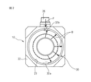
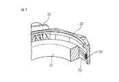
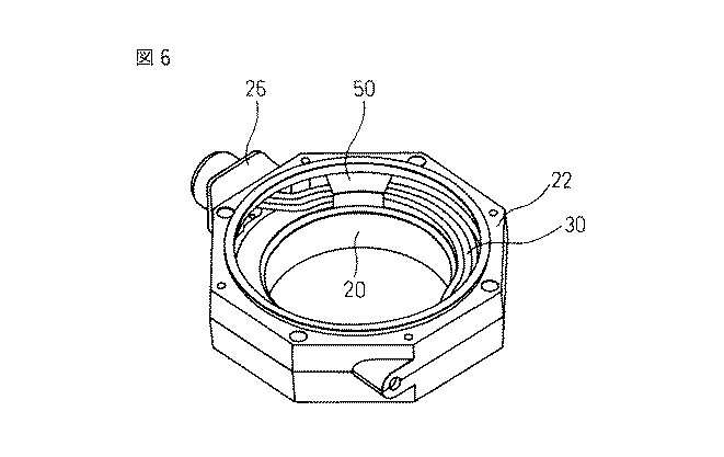
【解決手段】モータのステータコアに巻回されたステータ巻線と、ステータコアの一端側でステータ巻線の延長部を覆うカバー22に装着された電気コネクタ26とを電気的に相互接続するリード線30の固定構造において、リード線30が1次最小座屈荷重以上で2次最小座屈荷重以下の長さを有してカバー22内に配線され、リード線30が横方向の曲Bげにより、リード線30の側部がカバー22の内壁面22に当接して固定されている。
【選択図】図2
Description
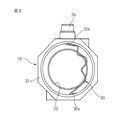
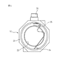
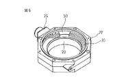
10 ステータ
22,40 フロントカバー
23 内壁面
30 リード線
34 ステータ巻線の延長部分
35 ケーブル
42 周壁
44 保持溝
Claims (4)
- モータのステータコアに巻回されたステータ巻線と、前記ステータコアの一端側で前記ステータ巻線の延長部を覆うカバーに装着された電気コネクタとを電気的に相互接続するリード線の固定方法において、
前記リード線を1次最小座屈荷重以上で2次最小座屈荷重以下の座屈荷重で座屈する長さとして前記ハウジング内に配線することと、
前記リード線が前記ステータ巻線に接続する一端又は前記リード線が前記電気コネクタに接続する他端に縦方向の圧縮荷重を加えて前記リード線を横方向に曲げることで、前記リード線を前記ハウジングの内壁に当接させて固定することと、
を備えたリード線の固定方法。 - モータのステータコアに巻回されたステータ巻線と、前記ステータコアの一端側で前記ステータ巻線の延長部を覆うカバーに装着された電気コネクタとを電気的に相互接続するリード線の固定構造において、
前記リード線が1次最小座屈荷重以上で2次最小座屈荷重以下の座屈荷重で座屈する長さを有して前記カバー内に配線され、前記リード線が横方向の曲げにより、該リード線が前記カバーの内壁面に当接して固定されているリード線の固定構造。 - 前記リード線が、前記ステータ巻線の延長部分と、該延長部分に続くケーブルとを備え、前記延長部分と前記ケーブルとが同等の曲げ剛性を有する請求項2記載のリード線の固定構造。
- 前記ハウジングの壁部に、前記リード線を保持するための溝が設けられている請求項2又は3記載のリード線の固定構造。
Priority Applications (1)
| Application Number | Priority Date | Filing Date | Title |
|---|---|---|---|
| JP2008192697A JP5203835B2 (ja) | 2008-07-25 | 2008-07-25 | リード線の固定方法及びリード線の固定構造 |
Applications Claiming Priority (1)
| Application Number | Priority Date | Filing Date | Title |
|---|---|---|---|
| JP2008192697A JP5203835B2 (ja) | 2008-07-25 | 2008-07-25 | リード線の固定方法及びリード線の固定構造 |
Publications (2)
| Publication Number | Publication Date |
|---|---|
| JP2010035289A true JP2010035289A (ja) | 2010-02-12 |
| JP5203835B2 JP5203835B2 (ja) | 2013-06-05 |
Family
ID=41739122
Family Applications (1)
| Application Number | Title | Priority Date | Filing Date |
|---|---|---|---|
| JP2008192697A Expired - Fee Related JP5203835B2 (ja) | 2008-07-25 | 2008-07-25 | リード線の固定方法及びリード線の固定構造 |
Country Status (1)
| Country | Link |
|---|---|
| JP (1) | JP5203835B2 (ja) |
Cited By (1)
| Publication number | Priority date | Publication date | Assignee | Title |
|---|---|---|---|---|
| JP2013038939A (ja) * | 2011-08-09 | 2013-02-21 | Toyota Motor Corp | 回転電機 |
Citations (4)
| Publication number | Priority date | Publication date | Assignee | Title |
|---|---|---|---|---|
| JPH0819203A (ja) * | 1994-06-30 | 1996-01-19 | Aichi Electric Co Ltd | 電動機のリード線引出装置 |
| JP2000041371A (ja) * | 1998-07-21 | 2000-02-08 | Aichi Electric Co Ltd | ブラシレスモータ |
| JP2004343831A (ja) * | 2003-05-13 | 2004-12-02 | Fanuc Ltd | 電動機 |
| JP2006098180A (ja) * | 2004-09-29 | 2006-04-13 | Citizen Watch Co Ltd | 電子体温計の製造方法 |
-
2008
- 2008-07-25 JP JP2008192697A patent/JP5203835B2/ja not_active Expired - Fee Related
Patent Citations (4)
| Publication number | Priority date | Publication date | Assignee | Title |
|---|---|---|---|---|
| JPH0819203A (ja) * | 1994-06-30 | 1996-01-19 | Aichi Electric Co Ltd | 電動機のリード線引出装置 |
| JP2000041371A (ja) * | 1998-07-21 | 2000-02-08 | Aichi Electric Co Ltd | ブラシレスモータ |
| JP2004343831A (ja) * | 2003-05-13 | 2004-12-02 | Fanuc Ltd | 電動機 |
| JP2006098180A (ja) * | 2004-09-29 | 2006-04-13 | Citizen Watch Co Ltd | 電子体温計の製造方法 |
Cited By (1)
| Publication number | Priority date | Publication date | Assignee | Title |
|---|---|---|---|---|
| JP2013038939A (ja) * | 2011-08-09 | 2013-02-21 | Toyota Motor Corp | 回転電機 |
Also Published As
| Publication number | Publication date |
|---|---|
| JP5203835B2 (ja) | 2013-06-05 |
Similar Documents
| Publication | Publication Date | Title |
|---|---|---|
| CN108028556B (zh) | 旋转电机 | |
| JP5109466B2 (ja) | 回転電機用ステータ、それに使用するバスバーユニット及びそのバスバー用端子とコイル端末との接続構造 | |
| JP5953672B2 (ja) | モータ | |
| JP6267907B2 (ja) | バスバーユニットおよびブラシレスモータ | |
| CN103733481B (zh) | 旋转电机和旋转电机的制造方法 | |
| JP6075174B2 (ja) | モータ用接続部材及びモータ装置 | |
| JP4609190B2 (ja) | 車両用回転電機 | |
| US7859164B2 (en) | Armature laminations | |
| JP3741600B2 (ja) | 電動機の固定子 | |
| EP3476021B1 (en) | Stator and motor having the same | |
| JP6614067B2 (ja) | 回転電機の固定子 | |
| US7545063B2 (en) | Wire-connection structure of motor | |
| CN104756370B (zh) | 旋转电机的定子 | |
| JP2008278704A (ja) | 回転電機用ステータ、そのコイル端末とバスバー用端子との接続構造及びその接続方法 | |
| US10056797B2 (en) | Stator for rotating electric machine | |
| JPH11150904A (ja) | ステータ用接続端子 | |
| US7646131B2 (en) | Permanent magnet synchronous machine with flat-wire windings | |
| US10320256B2 (en) | Method for manufacturing stator of rotary electric machine including a cassette coil | |
| JP6124493B1 (ja) | 内燃機関用回転電機およびそのステータ | |
| US20190393742A1 (en) | Method for making stator of rotary electrical machine | |
| WO2020022338A1 (ja) | コイルの端子接続方法、ツイスト治具及び回転電機のステータ | |
| JP5151300B2 (ja) | ステータおよび回転電機 | |
| JP2016059130A (ja) | 回転電機のステータ | |
| JP6281266B2 (ja) | 回転電機の端子接続構造 | |
| JP4137864B2 (ja) | 回転電機のステータ |
Legal Events
| Date | Code | Title | Description |
|---|---|---|---|
| A621 | Written request for application examination |
Free format text: JAPANESE INTERMEDIATE CODE: A621 Effective date: 20110405 |
|
| A977 | Report on retrieval |
Free format text: JAPANESE INTERMEDIATE CODE: A971007 Effective date: 20121219 |
|
| TRDD | Decision of grant or rejection written | ||
| A01 | Written decision to grant a patent or to grant a registration (utility model) |
Free format text: JAPANESE INTERMEDIATE CODE: A01 Effective date: 20130122 |
|
| A61 | First payment of annual fees (during grant procedure) |
Free format text: JAPANESE INTERMEDIATE CODE: A61 Effective date: 20130214 |
|
| R150 | Certificate of patent or registration of utility model |
Ref document number: 5203835 Country of ref document: JP Free format text: JAPANESE INTERMEDIATE CODE: R150 Free format text: JAPANESE INTERMEDIATE CODE: R150 |
|
| FPAY | Renewal fee payment (event date is renewal date of database) |
Free format text: PAYMENT UNTIL: 20160222 Year of fee payment: 3 |
|
| LAPS | Cancellation because of no payment of annual fees |