JP2010033930A - Vehicular lighting fixture - Google Patents
Vehicular lighting fixture Download PDFInfo
- Publication number
- JP2010033930A JP2010033930A JP2008195947A JP2008195947A JP2010033930A JP 2010033930 A JP2010033930 A JP 2010033930A JP 2008195947 A JP2008195947 A JP 2008195947A JP 2008195947 A JP2008195947 A JP 2008195947A JP 2010033930 A JP2010033930 A JP 2010033930A
- Authority
- JP
- Japan
- Prior art keywords
- light source
- source unit
- distribution pattern
- light
- cut line
- Prior art date
- Legal status (The legal status is an assumption and is not a legal conclusion. Google has not performed a legal analysis and makes no representation as to the accuracy of the status listed.)
- Granted
Links
Images

Abstract
Description
本発明は、自動車のヘッドランプを始めとしてフォグランプ,リヤコンビネーションランプ等に用いられる車両用灯具に関する。 The present invention relates to a vehicular lamp used for a headlamp of an automobile, a fog lamp, a rear combination lamp, and the like.
従来、自動車用ヘッドランプとして、例えば、特許文献1に示されているように、1つの灯具ですれ違い配光パターンが左側走行配光パターンと、右側走行配光パターンと、に切り替え可能としたものが知られている。 Conventionally, as a headlight for an automobile, for example, as shown in Patent Document 1, a light distribution pattern that can be switched between a left traveling light distribution pattern and a right traveling light distribution pattern with one lamp can be switched. It has been known.
これは、配光パターンがそれぞれ異なる3つの光源ユニットを1つの灯具ハウジングに収納して構成され、左側走行用と右側走行用とで仕様の異なる車種に応じて、前記3つの光源ユニットのうち1つの光源ユニットの機能を停止するようにしたものである。
前記従来の構造では、配光パターンを左側走行用または右側走行用に切り替えた場合、前記3つの光源ユニットのうち1つの光源ユニットを全く使用しないため、高価な光源ユニットが無駄となってコスト的に不利となってしまうことは否めない。 In the conventional structure, when the light distribution pattern is switched to the left traveling or the right traveling, one of the three light source units is not used at all, so that an expensive light source unit is wasted and costly. It is undeniable that it will be disadvantageous.
また、複数の光源ユニットが必要となるため、灯具が大型化して車体への組付けレイアウトに制約を与えてしまう。 In addition, since a plurality of light source units are required, the lamp becomes large and restricts the assembly layout to the vehicle body.
そこで、本発明は1つの光源ユニットで、左側走行用と右側走行用とに配光パターンを任意に切り替えることができ、かつ、小型化が可能な車両用灯具を提供するものである。 Therefore, the present invention provides a vehicular lamp that can switch the light distribution pattern arbitrarily for left-side traveling and right-side traveling with a single light source unit and that can be miniaturized.
本発明の車両用灯具にあっては、光源の出射光を灯具前方に照射して所定の配光パターンを形成する光源ユニットを、該光源ユニットの光軸または光軸と略平行な軸を中心に回動可能に配設して、前記配光パターンを切り替え可能としたことを主要な特徴としている。 In the vehicular lamp of the present invention, the light source unit that forms a predetermined light distribution pattern by irradiating the emitted light of the light source in front of the lamp is centered on the optical axis of the light source unit or an axis substantially parallel to the optical axis. The main feature is that the light distribution pattern can be switched by being rotatably arranged.
前記光源ユニットを、光軸または光軸と略平行な軸を中心に時計回り、または反時計回りに略同一の傾斜角度に回動すると、前記配光パターンが左右方向に切り替えられる。 When the light source unit is rotated clockwise or counterclockwise at substantially the same inclination angle about an optical axis or an axis substantially parallel to the optical axis, the light distribution pattern is switched in the left-right direction.
本発明の車両用灯具によれば、光源ユニットを、光軸または光軸と略平行な軸を中心とした正・逆方向(時計方向、反時計方向)に回動することで、灯具前方に照射される配光パターンを左右方向に切り替えることができる。 According to the vehicular lamp of the present invention, the light source unit is rotated forward and backward (clockwise and counterclockwise) about the optical axis or an axis substantially parallel to the optical axis, thereby moving the light source unit forward of the lamp. The light distribution pattern to be irradiated can be switched in the left-right direction.
このため、配光パターンを上縁に水平カットラインと傾斜カットラインとからなる所定形状のカットラインを有するすれ違い配光パターンとした場合、前記光源ユニットの回動制御で左側走行用と右側走行用とに、配光パターンを任意に切り替えることができる。 For this reason, when the light distribution pattern is a passing light distribution pattern having a cut line having a predetermined shape consisting of a horizontal cut line and an inclined cut line at the upper edge, the left light traveling and the right traveling are controlled by the rotation control of the light source unit. In addition, the light distribution pattern can be arbitrarily switched.
このように、本発明の車両用灯具によれば、1つの光源ユニットでも、その回動制御で配光パターンを、左側走行用の配光パターンと右側走行用の配光パターンとに切り替えて現出できるため、前記従来の車両用灯具に較べて大幅なコストダウンを図ることができると共に、小型化を実現することができる。 As described above, according to the vehicular lamp of the present invention, even with one light source unit, the light distribution pattern is switched between the light distribution pattern for the left traveling and the light distribution pattern for the right traveling by the rotation control. Therefore, the cost can be greatly reduced as compared with the conventional vehicular lamp, and downsizing can be realized.
以下、本発明の一実施形態を車両用灯具としてヘッドランプを例に採って詳述する。 Hereinafter, an embodiment of the present invention will be described in detail by taking a headlamp as an example of a vehicular lamp.
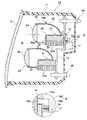
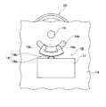
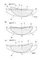
図1は本発明の一実施形態に係るヘッドランプの断面図、図2は同ヘッドランプにおけるブラケットの部分背面図、図3は光源ユニットの時計方向回動状態(A)と、配光パターン切り替え途中における中立点(B)と、反時計方向回動状態(C)とを示す背面図、図4は図3の(A),(B),(C)に示す光源ユニットの回動状態に対応した配光パターンの変化状態を(A),(B),(C)にて示す説明図である。 1 is a cross-sectional view of a headlamp according to an embodiment of the present invention, FIG. 2 is a partial rear view of a bracket in the headlamp, and FIG. 3 is a clockwise rotation state (A) of a light source unit and a light distribution pattern switching. FIG. 4 is a rear view showing a neutral point (B) and a counterclockwise rotation state (C) in the middle, and FIG. 4 is a rotation state of the light source unit shown in (A), (B), and (C) of FIG. It is explanatory drawing which shows the change state of a corresponding light distribution pattern by (A), (B), (C).
図1に示す本実施形態のヘッドランプ10は、灯具ハウジング11と、該灯具ハウジング11の前側開口部を閉塞したアウターレンズ12と、これら灯具ハウジング11とアウターレンズ12とで構成された灯室13内に配設された光源ユニット20と、を備えている。
A
光源ユニット20は、光源21の出射光を前記アウターレンズ12を通して車両前方(灯具前方)に照射して、図4に示す上縁に所定形状のカットラインCを有する配光パターンPを形成するものである。
The
この光源ユニット20は、該光源ユニット20の中心部分、例えば、前記カットラインCを形成するシェード25の略中心(レンズ後側焦点F)を通り、光軸と略平行な軸0を中心に回動可能に配設され、前記配光パターンPを切り替え可能としている。
The
具体的には、前記灯室13内には板状のブラケット14が縦置きに配置され、前記光源ユニット20は、その背部が前記軸0の延長上で支軸15を介して前記ブラケット14に回動可能に軸支されている。このブラケット14にユニット回動機構16が固定され、該ユニット回動機構16がその駆動伝達機構18を介して前記光源ユニット20に連結されていて、前記光源ユニット20はこのユニット回動機構16の作動によって回動制御される。
Specifically, a plate-
前記ユニット回動機構16は、前記支軸15よりも下方位置でブラケット14の背面に固設されたモーター等の回転駆動部17と、該回転駆動部17の動力を光源ユニット20に伝達する駆動伝達機構18と、で構成することができる。
The
駆動伝達機構18は、例えば、図2に示すように、前記回転駆動部17側の変速ギヤ18aと、該変速ギヤ18aに噛合したセクタギャ18bとで構成される。このセクタギャ18bには左右一対のアーム部18cが突設されている。アーム部18cは、前記ブラケット14に支軸15を中心として形成された円弧状スリット14aに挿通して光源ユニット20の背部に結合され、これにより、光源ユニット20の回転駆動系が構成される。
For example, as shown in FIG. 2, the
前記光源ユニット20は、本実施形態では、例えば、発光ダイオード(LED)等の半導体発光素子を光源21とし、その光源支持台22にリフレクタ23,集光レンズ(凸レンズ)24等の光学系部品が集約的に配設されたプロジェクタランプで構成されている。
In the present embodiment, the
光源支持台22は、下側に複数の冷却フィン22aを備えたヒートシンク部材で構成されている。光源21は、この光源支持台22の略水平な上側面に、その発光中心が集光レンズ24の光軸上に位置するように配設されている。リフレクタ23は、前記光源支持台22の上側面に光源21の上方を覆って設けられ、このリフレクタ23は、図1に示す鉛直断面で前記光源21の略発光中心を第1焦点とする回転楕円面を基調とした自由曲面に形成されている。リフレクタ23の第2焦点は集光レンズ24の後側焦点Fの近傍に設定され、ここに前記シェード25が形成されている。従って、本実施形態にあっては集光レンズ24の光軸を前記軸0としている。集光レンズ24はレンズホルダー24aに保持され、該レンズホルダー24aの後端を前記リフレクタ23の前端縁部に結合して、これら光源21,光源支持台22,リフレクタ23,集光レンズ24等でプロジェクタランプが構成される。
The light
従って、本実施形態では前記支軸15およびセクタギャ18bのアーム部18cは、前記光源支持台22の背面に結合されている。
Therefore, in this embodiment, the
図4は前記光源ユニット20の照射光により、車両前方の仮想スクリーン上に形成される配光パターンPを示している。この配光パターンPは、図4(A),(C)に示すように上縁の一側に略水平方向に延びる水平カットラインa,a′と、上縁の他側にこの水平カットラインa,a′から斜め上方に傾斜して立上がる傾斜カットラインb,b′と、からなるカットラインCを有するすれ違い配光パターンとして形成される。前記水平カットラインa,a′と、傾斜カットラインb,b′との交点は、前記仮想スクリーン上のH−H線よりもやや下方のV−V線上となるように形成されている。図4(A)は水平カットラインaが右側に形成され、傾斜カットラインbが左側に形成された左側走行配光パターンPLを示している。また、図4(C)は水平カットラインa′が左側に形成され、傾斜カットラインb′が右側に形成された右側走行配光パターンPRを示している。
FIG. 4 shows a light distribution pattern P formed on the virtual screen in front of the vehicle by the irradiation light of the
前記光源ユニット20は、前記配光パターンPの水平カットラインa,a′と傾斜カットラインb,b′とが左右対称的に逆転可能なように、前記ユニット回動機構16によって図3(B)に示す配光パターン切り替え途中における中立点を境に、図3(A),(C)に示すように略同一の傾斜角度θで正・逆方向に回動制御される。
The
図3(A)は光源ユニット20が背面視して時計方向(正方向)に角度θで回動された場合で、このとき、配光パターンPは図4(A)に示すように傾斜カットラインbが左上がりの左側走行配光パターンPLとして得られる。図3(C)は光源ユニット20が背面視して反時計方向(逆方向)に角度θで回動された場合で、このとき、配光パターンPは図4(C)に示すように傾斜カットラインb′が右上がりの右側走行配光パターンPRとして得られる。光源ユニット20が配光パターン切り替え途中における図3(B)に示す中立位置にあるときは、配光パターンPは図4(B)に示すように、上縁のカットラインCが略V字状となる前記V−V線を境とした左右線対称パターンとなる。
FIG. 3A shows a case where the
本実施形態では、前記光源ユニット20の下側に、図4に符号Poで示す上縁に略水平なカットラインCoを有する拡散配光パターンを形成する拡散光源ユニット30が配設され、これら光源ユニット20の照射光と拡散光源ユニット30の照射光とにより、前記配光パターンPと拡散配光パターンPoとが合成されたすれ違い配光パターンが得られるようにしている。
In the present embodiment, a diffused
この拡散光源ユニット30は、前記光源ユニット20と同様に半導体発光素子を光源31とし、ヒートシンク機能を有する光源支持台32にこの光源31と、リフレクタ33,集光レンズ34等を集約的に配設したプロジェクタランプが用いられ、前記光源支持台32の背面を前記ブラケット14の下側延長部に当接して該ブラケット14に締結固定されている。
As in the
このブラケット14と灯具ハウジング11の背壁とに跨って、複数の対をなすボルトとナットからなる光軸調整機構40が設けられ、該光軸調整機構40によりヘッドランプ10の光軸調整が行われるようになっている。
An optical
以上の構成からなる本実施形態のヘッドランプ10によれば、光源ユニット20を、前記回動中心軸0を中心に図3(B)に示す配光パターン切り替え途中における中立点から、同図(A)に示す時計方向、または、同図(C)に示す反時計方向に同一角度θに回動することによって、該光源ユニット20により形成される配光パターンPを左右対称的に変化させることができる。また、光源ユニット20の回動は、円弧状スリット14aの左右いずれかの端部に駆動伝達機構(セクタギャ)を突き当てることによっても、左右対称的に配光パターンを変化させることができる。
According to the
特に本実施形態では、前記光源ユニット20で形成される配光パターンPは、上縁に水平カットラインa,a′と傾斜カットラインb,b′とからなる所定形状のカットラインCを有するすれ違い配光パターンとしているため、前述のように光源ユニット20を配光パターン切り替え途中における中立点から角度θで時計方向に回動した場合には、図4(A)に示すように傾斜カットラインbが左上がりの左側走行配光パターンPLが得られ、これとは逆に光源ユニット20を角度θで反時計方向に回動した場合には、図4(C)に示すように前記左側走行配光パターンPLと左右対称に逆転変化して、傾斜カットラインb′が右上がりの右側走行配光パターンPRが得られる。
In particular, in the present embodiment, the light distribution pattern P formed by the
従って、ヘッドランプ10を左車線走行用車両と右車線走行用車両とに共用化する場合に、1つの光源ユニット20でも、その回動制御により配光パターンPを、左側走行用の配光パターンPLと右側走行用の配光パターンPRとに切り替えて現出できるため、前記従来のものと較べて大幅なコストダウンを実現することができると共に、ヘッドランプ10の小型化を実現できる。
Therefore, when the
また、前記光源ユニット20は、その背部をシェード25の略中心を通り、光軸と略平行な軸0の延長上で支軸15を介して灯具ハウジング側のブラケット14に回動可能に軸支し、該ブラケット14にユニット回動機構16を固定して、該ユニット回動機構16をその駆動伝達機構18を介して光源ユニット20と連結した簡単な構造で前記回動制御を行わせるようにしているので、大幅な構造変更を伴うことなくコスト的に有利に得ることができる。
The
更に、光源ユニット20には、半導体発光素子を光源21として、その光源支持台22にリフレクタ23,集光レンズ24等の光学系部品を集約的に配設したプロジェクタランプが用いられているが、この光源支持台22と前記ブラケット14とを前記支軸15と、ユニット回動機構16とにより組付けて、前記光源支持台22自体を光源ユニット20の回動支持部としているため、光源ユニット20に特別に回動支持部を設ける必要がなく、大幅な設計変更を伴うことがないのでこの点からもコスト的に有利に得ることができる。
Further, the
しかも、半導体発光素子(光源21)で発生する熱は、ヒートシンク部材等で構成される光源支持台22から放熱されることは勿論、該光源支持台22からブラケット14側への熱伝達性が良好となるので、光源21の放熱効果を高めることもできる。
Moreover, the heat generated in the semiconductor light emitting element (light source 21) is radiated from the light
そして、本実施形態のように光源ユニットが符号20,30で示すように複数備えられている場合、カットライン形成用の光源ユニット20を回動可能に構成することで、集光配光を可変とすることができる。また、複数の光源ユニットとして集光用ユニットと拡散用ユニットとを設けた場合、集光用ユニットのみを回動可能なユニットとすることで、全体の配光を大きく変更することなく、カットラインのみを切り替えることができ、ユニット回動機構も小型にすることができる。
When a plurality of light source units are provided as indicated by
なお、前記実施形態ではヘッドランプ10におけるすれ違い配光パターンPのカットラインCを切り替える例について説明したが、この他、光源ユニット20の前記回動制御によって、均一的な配光から、ホットゾーンを有する遠方視認性に優れた配光に切り替え制御することも可能である。また、本発明は前記ヘッドランプの他、フォグランプに、また場合によってはリヤコンビネーションランプに適用することもできる。更に、光源ユニット20の左右配光の切り替えは、手動によっても可能である。
In the above embodiment, the example of switching the cut line C of the passing light distribution pattern P in the
10 ヘッドランプ(車両用灯具)
11 灯具ハウジング
14 ブラケット
15 支軸
16 ユニット回動機構
20 光源ユニット
21 光源
22 光源支持台
23 リフレクタ
24 集光レンズ
25 シェード
P すれ違い配光パターン
C カットライン
a,a′ 水平カットライン
b,b′ 傾斜カットライン
0 回転中心軸
10 Headlamp (vehicle lamp)
DESCRIPTION OF
Claims (5)
Priority Applications (1)
| Application Number | Priority Date | Filing Date | Title |
|---|---|---|---|
| JP2008195947A JP5088261B2 (en) | 2008-07-30 | 2008-07-30 | Vehicle lighting |
Applications Claiming Priority (1)
| Application Number | Priority Date | Filing Date | Title |
|---|---|---|---|
| JP2008195947A JP5088261B2 (en) | 2008-07-30 | 2008-07-30 | Vehicle lighting |
Publications (2)
| Publication Number | Publication Date |
|---|---|
| JP2010033930A true JP2010033930A (en) | 2010-02-12 |
| JP5088261B2 JP5088261B2 (en) | 2012-12-05 |
Family
ID=41738158
Family Applications (1)
| Application Number | Title | Priority Date | Filing Date |
|---|---|---|---|
| JP2008195947A Expired - Fee Related JP5088261B2 (en) | 2008-07-30 | 2008-07-30 | Vehicle lighting |
Country Status (1)
| Country | Link |
|---|---|
| JP (1) | JP5088261B2 (en) |
Cited By (3)
| Publication number | Priority date | Publication date | Assignee | Title |
|---|---|---|---|---|
| JP2011228150A (en) * | 2010-04-21 | 2011-11-10 | Mitsubishi Electric Corp | Lamp unit and video projection device |
| JP2014007048A (en) * | 2012-06-25 | 2014-01-16 | Koito Mfg Co Ltd | Vehicle headlight |
| KR101605702B1 (en) * | 2013-08-13 | 2016-03-23 | 에스엘 주식회사 | Automotive lamp and method for controlling the automotive lamp |
Citations (7)
| Publication number | Priority date | Publication date | Assignee | Title |
|---|---|---|---|---|
| JPH0765605A (en) * | 1993-08-25 | 1995-03-10 | Koito Mfg Co Ltd | Head lamp for automobile |
| JPH11329010A (en) * | 1998-04-20 | 1999-11-30 | Valeo Vision | Automobile headlight capable of emitting left or right side traveling beam |
| JP2000164021A (en) * | 1998-11-20 | 2000-06-16 | Ichikoh Ind Ltd | Headlight |
| JP2003141912A (en) * | 2001-08-24 | 2003-05-16 | Stanley Electric Co Ltd | Headlight for vehicle |
| JP2003178608A (en) * | 2001-12-07 | 2003-06-27 | Ichikoh Ind Ltd | Vehicular lamp |
| JP2005235708A (en) * | 2004-02-23 | 2005-09-02 | Ichikoh Ind Ltd | Projector-type vehicular lighting fixture |
| JP2006196410A (en) * | 2005-01-17 | 2006-07-27 | Koito Mfg Co Ltd | Headlamp for vehicle |
-
2008
- 2008-07-30 JP JP2008195947A patent/JP5088261B2/en not_active Expired - Fee Related
Patent Citations (7)
| Publication number | Priority date | Publication date | Assignee | Title |
|---|---|---|---|---|
| JPH0765605A (en) * | 1993-08-25 | 1995-03-10 | Koito Mfg Co Ltd | Head lamp for automobile |
| JPH11329010A (en) * | 1998-04-20 | 1999-11-30 | Valeo Vision | Automobile headlight capable of emitting left or right side traveling beam |
| JP2000164021A (en) * | 1998-11-20 | 2000-06-16 | Ichikoh Ind Ltd | Headlight |
| JP2003141912A (en) * | 2001-08-24 | 2003-05-16 | Stanley Electric Co Ltd | Headlight for vehicle |
| JP2003178608A (en) * | 2001-12-07 | 2003-06-27 | Ichikoh Ind Ltd | Vehicular lamp |
| JP2005235708A (en) * | 2004-02-23 | 2005-09-02 | Ichikoh Ind Ltd | Projector-type vehicular lighting fixture |
| JP2006196410A (en) * | 2005-01-17 | 2006-07-27 | Koito Mfg Co Ltd | Headlamp for vehicle |
Cited By (3)
| Publication number | Priority date | Publication date | Assignee | Title |
|---|---|---|---|---|
| JP2011228150A (en) * | 2010-04-21 | 2011-11-10 | Mitsubishi Electric Corp | Lamp unit and video projection device |
| JP2014007048A (en) * | 2012-06-25 | 2014-01-16 | Koito Mfg Co Ltd | Vehicle headlight |
| KR101605702B1 (en) * | 2013-08-13 | 2016-03-23 | 에스엘 주식회사 | Automotive lamp and method for controlling the automotive lamp |
Also Published As
| Publication number | Publication date |
|---|---|
| JP5088261B2 (en) | 2012-12-05 |
Similar Documents
| Publication | Publication Date | Title |
|---|---|---|
| KR101047371B1 (en) | Headlights for vehicles | |
| JP4771723B2 (en) | Vehicle lighting | |
| JP4515391B2 (en) | Vehicle headlamp | |
| JP6812120B2 (en) | Vehicle lighting fixtures and vehicles equipped with the vehicle lighting fixtures | |
| JP4895224B2 (en) | Vehicle lighting | |
| JP5758724B2 (en) | Vehicle headlamp | |
| JP2008153108A (en) | Vehicle lighting apparatus | |
| JP2010238605A (en) | Lighting fixture unit | |
| JP2007052955A (en) | Vehicular lighting fixture | |
| EP2546567B1 (en) | Vehicle headlight | |
| WO2016093154A1 (en) | Vehicular illumination device | |
| JP6211349B2 (en) | Vehicle lighting | |
| JP2007335311A (en) | Lamp for vehicle | |
| JP2008041558A (en) | Headlamp for vehicle | |
| JP2011100561A (en) | Headlight for vehicle | |
| JP6651797B2 (en) | Vehicle headlights | |
| JP2011081975A (en) | Vehicle headlight and reflector unit therefor | |
| JP6645018B2 (en) | Vehicle headlights | |
| JP2008027650A (en) | Lamp tool for vehicle | |
| JP5088261B2 (en) | Vehicle lighting | |
| JP2009163921A (en) | Vehicle headlight | |
| JP6503775B2 (en) | Vehicle lamp | |
| JP2014063603A (en) | Vehicular headlamp | |
| JP2009129572A (en) | Lamp for vehicle | |
| JP2013239408A (en) | Vehicular headlight |
Legal Events
| Date | Code | Title | Description |
|---|---|---|---|
| A621 | Written request for application examination |
Free format text: JAPANESE INTERMEDIATE CODE: A621 Effective date: 20110106 |
|
| A977 | Report on retrieval |
Free format text: JAPANESE INTERMEDIATE CODE: A971007 Effective date: 20120516 |
|
| A131 | Notification of reasons for refusal |
Free format text: JAPANESE INTERMEDIATE CODE: A131 Effective date: 20120518 |
|
| A521 | Request for written amendment filed |
Free format text: JAPANESE INTERMEDIATE CODE: A523 Effective date: 20120709 |
|
| TRDD | Decision of grant or rejection written | ||
| A01 | Written decision to grant a patent or to grant a registration (utility model) |
Free format text: JAPANESE INTERMEDIATE CODE: A01 Effective date: 20120814 |
|
| A01 | Written decision to grant a patent or to grant a registration (utility model) |
Free format text: JAPANESE INTERMEDIATE CODE: A01 |
|
| A61 | First payment of annual fees (during grant procedure) |
Free format text: JAPANESE INTERMEDIATE CODE: A61 Effective date: 20120827 |
|
| FPAY | Renewal fee payment (event date is renewal date of database) |
Free format text: PAYMENT UNTIL: 20150921 Year of fee payment: 3 |
|
| R150 | Certificate of patent or registration of utility model |
Ref document number: 5088261 Country of ref document: JP Free format text: JAPANESE INTERMEDIATE CODE: R150 Free format text: JAPANESE INTERMEDIATE CODE: R150 |
|
| R250 | Receipt of annual fees |
Free format text: JAPANESE INTERMEDIATE CODE: R250 |
|
| R250 | Receipt of annual fees |
Free format text: JAPANESE INTERMEDIATE CODE: R250 |
|
| R250 | Receipt of annual fees |
Free format text: JAPANESE INTERMEDIATE CODE: R250 |
|
| R250 | Receipt of annual fees |
Free format text: JAPANESE INTERMEDIATE CODE: R250 |
|
| R250 | Receipt of annual fees |
Free format text: JAPANESE INTERMEDIATE CODE: R250 |
|
| R250 | Receipt of annual fees |
Free format text: JAPANESE INTERMEDIATE CODE: R250 |
|
| LAPS | Cancellation because of no payment of annual fees |