JP2010033434A - 無人搬送車用誘導テープ認識装置 - Google Patents
無人搬送車用誘導テープ認識装置 Download PDFInfo
- Publication number
- JP2010033434A JP2010033434A JP2008196515A JP2008196515A JP2010033434A JP 2010033434 A JP2010033434 A JP 2010033434A JP 2008196515 A JP2008196515 A JP 2008196515A JP 2008196515 A JP2008196515 A JP 2008196515A JP 2010033434 A JP2010033434 A JP 2010033434A
- Authority
- JP
- Japan
- Prior art keywords
- tape
- value
- sensor
- output value
- sensors
- Prior art date
- Legal status (The legal status is an assumption and is not a legal conclusion. Google has not performed a legal analysis and makes no representation as to the accuracy of the status listed.)
- Granted
Links
- 230000006698 induction Effects 0.000 claims description 40
- 230000007246 mechanism Effects 0.000 claims description 27
- 238000012937 correction Methods 0.000 claims description 26
- 238000012935 Averaging Methods 0.000 claims description 2
- 238000001514 detection method Methods 0.000 abstract description 24
- 238000000034 method Methods 0.000 description 21
- XEEYBQQBJWHFJM-UHFFFAOYSA-N Iron Chemical compound [Fe] XEEYBQQBJWHFJM-UHFFFAOYSA-N 0.000 description 20
- 229910052742 iron Inorganic materials 0.000 description 10
- 238000004364 calculation method Methods 0.000 description 8
- 239000000463 material Substances 0.000 description 7
- 238000010586 diagram Methods 0.000 description 5
- 230000000694 effects Effects 0.000 description 5
- 230000004907 flux Effects 0.000 description 5
- 230000035945 sensitivity Effects 0.000 description 4
- 238000009434 installation Methods 0.000 description 3
- 238000012423 maintenance Methods 0.000 description 3
- 238000004519 manufacturing process Methods 0.000 description 3
- 230000032683 aging Effects 0.000 description 2
- 230000006866 deterioration Effects 0.000 description 2
- 238000005259 measurement Methods 0.000 description 2
- 230000003287 optical effect Effects 0.000 description 2
- 238000012360 testing method Methods 0.000 description 2
- 238000003491 array Methods 0.000 description 1
- 230000008859 change Effects 0.000 description 1
- 238000011109 contamination Methods 0.000 description 1
- 230000007423 decrease Effects 0.000 description 1
- 238000009795 derivation Methods 0.000 description 1
- 238000003745 diagnosis Methods 0.000 description 1
- 235000013399 edible fruits Nutrition 0.000 description 1
- 230000005674 electromagnetic induction Effects 0.000 description 1
- 238000012840 feeding operation Methods 0.000 description 1
- 238000009408 flooring Methods 0.000 description 1
- 230000006872 improvement Effects 0.000 description 1
- 239000000696 magnetic material Substances 0.000 description 1
- 238000010606 normalization Methods 0.000 description 1
- 238000012545 processing Methods 0.000 description 1
- 230000009467 reduction Effects 0.000 description 1
- 229910001220 stainless steel Inorganic materials 0.000 description 1
- 239000010935 stainless steel Substances 0.000 description 1
- 229920003002 synthetic resin Polymers 0.000 description 1
- 239000000057 synthetic resin Substances 0.000 description 1
- 239000002023 wood Substances 0.000 description 1
Images


Landscapes
- Control Of Position, Course, Altitude, Or Attitude Of Moving Bodies (AREA)
Abstract
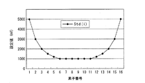
【解決手段】稼働前に、誘導テープが存在する状態で各センサの出力値Von(i)を取得し、誘導テープが存在しない状態で各センサの出力値Vof(i)を取得し、各センサに対して、Vof(i)をオフセット値O(i)として記憶し、Von(i)とVof(i)との差をレンジ値R(i)として記憶し、さらに、基準値Std(i)をR(i)で除した値をゲイン値G(i)として記憶し、稼働時に、各センサの出力値Vs(i)とそのセンサのO(i)との差にそのセンサのG(i)を掛けた値をそのセンサの補正出力値Vx(i)とし、各センサのVx(i)に基づき誘導テープの位置を認識することによって前記の課題を解決する。
【選択図】図5
Description
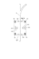
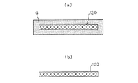
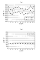
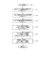
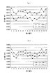
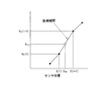
ここで、図1は、本実施例の無人搬送車用誘導テープ認識装置が適用される無人搬送車の概要を示す概念図である。図2は、複数のセンサの初期設定時におけるセンサと誘導テープとの位置関係を示した平面図であり、図3は、誘導テープの位置の認識を行う際におけるセンサと誘導テープとの位置関係を示した平面図であり、図4は、誘導テープが存在する状態における複数のセンサのそれぞれの出力値と、誘導テープが存在しない状態における複数のセンサのそれぞれの出力値と、両者の差であるレンジ値とを示したグラフであり、図5は、センサ初期設定のフローを示したフローチャートであり、図6は、センサ出力値から誘導テープの位置を認識するフローを示したフローチャートであり、図7は、誘導テープの違いによるセンサ出力値の違いを示したグラフであり、図8は、基準値Std(i)の設定例であり、図9は、基準値Std(i)の別の設定例である。
そして、図2(a)に示すように、誘導テープGが存在する状態で磁気センサアレイ120を構成する各磁気センサの出力値、すなわちテープあり出力値Von(i)を取得する[S2]。
次に、図2(b)に示すように、誘導テープが存在しない状態で磁気センサアレイ120を構成する各磁気センサの出力値、すなわちテープなし出力値Vof(i)を取得する[S3]。ここで、各磁気センサごとのVon(i)及びVof(i)の値をグラフ化したものが図4(a)である。このグラフから明らかなように、磁気センサごとに出力値がかなりばらついている。
さらに、Von(i)とVof(i)との差をレンジ値R(i)として記憶する[S5]。各磁気センサごとのレンジ値R(i)の値をグラフ化したものが図4(b)である。このグラフから明らかなように、磁気センサごとのレンジ値R(i)は、1100mV程度である。
Xc=ΣX(i)・Vx(i)/ΣVx(i)
実施例2の無人搬送車用誘導テープ認識装置は、テープ位置認識機構のみが前述した実施例1の無人搬送車用誘導テープ認識装置と異なっているため、このテープ位置認識機構のみを以下に説明する。
Xth={(Vx(i+1)−Vth)・X(i)+(Vth−Vx(i))・X(i+1)}/(Vx(i+1)−Vx(i))
なお、図12において、y=250mm以上のところで、テープ右端位置が300mmで一定になっているのは、本実施例においては、センサ幅を300mmとしているため、これ以上は計算できないためである。
実施例3の無人搬送車用誘導テープ認識装置は、テープ位置認識機構のみが前述した実施例1の無人搬送車用誘導テープ認識装置と異なっているため、このテープ位置認識機構のみを以下に説明する。
実施例4の無人搬送車用誘導テープ認識装置は、センサ初期設定機構のみが前述した実施例1の無人搬送車用誘導テープ認識装置と異なっているため、このセンサ初期設定機構のみを以下に説明する。
110 ・・・ キャスタ輪
120 ・・・ 磁気センサアレイ
130 ・・・ 駆動輪
140 ・・・ 電動モータ
G ・・・ 誘導テープ
Claims (6)
- 搬送経路に沿って敷設された誘導テープの位置を無人搬送車に前記誘導テープと直交する方向に一列に設置された複数のセンサで認識する無人搬送車用誘導テープ認識装置において、
前記複数のセンサのそれぞれに対して、予め所定の基準値Std(i)を記憶し、前記誘導テープの位置の認識を行う前に、前記誘導テープが存在する状態における前記複数のセンサのそれぞれの出力値であるテープあり出力値Von(i)を取得し、前記誘導テープが存在しない状態における前記複数のセンサのそれぞれの出力値であるテープなし出力値Vof(i)を取得し、前記複数のセンサのそれぞれに対して、前記テープなし出力値Vof(i)をオフセット値O(i)として記憶するとともに、前記テープあり出力値Von(i)とテープなし出力値Vof(i)との差をレンジ値R(i)として記憶し、さらに、前記基準値Std(i)を前記レンジ値R(i)で除した値をゲイン値G(i)として記憶するセンサ初期設定機構と、
前記誘導テープの位置の認識を行う際に、前記複数のセンサのそれぞれの出力値Vs(i)と当該センサのオフセット値O(i)との差に当該センサのゲイン値G(i)を掛けた値を当該センサの補正出力値Vx(i)とするセンサ出力補正機構と、
前記複数のセンサのそれぞれの補正出力値Vx(i)に基づき誘導テープの位置を認識するテープ位置認識機構とを有することを特徴とする無人搬送車用誘導テープ認識装置。 - 前記テープ位置認識機構が、所定の閾値Vthを挟む補正出力値を出力している隣接する2つのセンサのそれぞれの補正出力値Vx(i)、Vx(i+1)及び位置X(i)、X(i+1)を直線補間し、前記閾値Vthに対応する位置Xthを演算し誘導テープの端として認識することを特徴とする請求項1記載の無人搬送車用誘導テープ認識装置。
- 前記テープ位置認識機構が、最も大きな補正出力値Vx(i)を出力するセンサの位置X(i)を前記誘導テープの中央として認識することを特徴とする請求項1又は請求項2記載の無人搬送車用誘導テープ認識装置。
- 前記テープ位置認識機構が、所定の閾値Vthを超えた補正出力値を出力しているセンサのそれぞれの補正出力値Vx(i)及び位置X(i)を
Xc=ΣX(i)・Vx(i)/ΣVx(i)
に基づき加重平均した結果Xcを前記誘導テープの中央として認識することを特徴とする請求項1又は請求項2記載の無人搬送車用誘導テープ認識装置。 - 前記基準値Std(i)の値が、右端及び左端に近いセンサほど大きく設定されていることを特徴とする請求項1乃至請求項4のいずれか記載の無人搬送車用誘導テープ認識装置。
- 前記誘導テープが磁気テープであり、前記センサが磁気センサであることを特徴とする請求項1乃至請求項5のいずれか記載の無人搬送車用誘導テープ認識装置。
Priority Applications (1)
| Application Number | Priority Date | Filing Date | Title |
|---|---|---|---|
| JP2008196515A JP5127625B2 (ja) | 2008-07-30 | 2008-07-30 | 無人搬送車用誘導テープ認識装置 |
Applications Claiming Priority (1)
| Application Number | Priority Date | Filing Date | Title |
|---|---|---|---|
| JP2008196515A JP5127625B2 (ja) | 2008-07-30 | 2008-07-30 | 無人搬送車用誘導テープ認識装置 |
Publications (2)
| Publication Number | Publication Date |
|---|---|
| JP2010033434A true JP2010033434A (ja) | 2010-02-12 |
| JP5127625B2 JP5127625B2 (ja) | 2013-01-23 |
Family
ID=41737802
Family Applications (1)
| Application Number | Title | Priority Date | Filing Date |
|---|---|---|---|
| JP2008196515A Active JP5127625B2 (ja) | 2008-07-30 | 2008-07-30 | 無人搬送車用誘導テープ認識装置 |
Country Status (1)
| Country | Link |
|---|---|
| JP (1) | JP5127625B2 (ja) |
Cited By (4)
| Publication number | Priority date | Publication date | Assignee | Title |
|---|---|---|---|---|
| JP2011013014A (ja) * | 2009-06-30 | 2011-01-20 | Makome Kenkyusho:Kk | 位置検出センサ |
| JP5525647B1 (ja) * | 2013-10-03 | 2014-06-18 | 株式会社マコメ研究所 | 位置検出装置 |
| US11573574B2 (en) | 2018-08-30 | 2023-02-07 | Canon Kabushiki Kaisha | Information processing apparatus, information processing method, information processing system, and storage medium |
| US12292485B2 (en) | 2021-03-19 | 2025-05-06 | Denso Corporation | Magnetic detection system |
-
2008
- 2008-07-30 JP JP2008196515A patent/JP5127625B2/ja active Active
Cited By (4)
| Publication number | Priority date | Publication date | Assignee | Title |
|---|---|---|---|---|
| JP2011013014A (ja) * | 2009-06-30 | 2011-01-20 | Makome Kenkyusho:Kk | 位置検出センサ |
| JP5525647B1 (ja) * | 2013-10-03 | 2014-06-18 | 株式会社マコメ研究所 | 位置検出装置 |
| US11573574B2 (en) | 2018-08-30 | 2023-02-07 | Canon Kabushiki Kaisha | Information processing apparatus, information processing method, information processing system, and storage medium |
| US12292485B2 (en) | 2021-03-19 | 2025-05-06 | Denso Corporation | Magnetic detection system |
Also Published As
| Publication number | Publication date |
|---|---|
| JP5127625B2 (ja) | 2013-01-23 |
Similar Documents
| Publication | Publication Date | Title |
|---|---|---|
| CA2824189C (en) | Automatic guided vehicle system and method | |
| JP4074999B2 (ja) | 搬送台車システム | |
| US9335149B2 (en) | Displacement sensor for contactlessly measuring a position by means of a plurality of magnetic field sensors arranged in series | |
| JP5333537B2 (ja) | 移動体システムと移動体の走行制御方法 | |
| US6971464B2 (en) | Driverless vehicle guidance system and method | |
| JP4438882B2 (ja) | 移動体システム | |
| CN201993114U (zh) | 一种磁导航传感器 | |
| US7703396B2 (en) | Carriage system | |
| JP7473351B2 (ja) | 長固定子リニアモーターの制御方法 | |
| US20110153135A1 (en) | Travel control device for unmanned conveyance vehicle | |
| JP5127625B2 (ja) | 無人搬送車用誘導テープ認識装置 | |
| EP2589972A2 (en) | Systems and methods for use in measuring current through a conductor | |
| JP4375565B2 (ja) | 走行台車システム | |
| KR101340503B1 (ko) | 양극형 자기유도 장치와 agv 유도 방법 | |
| JP2004086453A (ja) | 無人搬送車用誘導装置 | |
| JP2015022451A (ja) | 無人搬送車の位置検出方法 | |
| US9729100B2 (en) | Mobile body and mobile body system | |
| US9768721B2 (en) | Mobile body and mobile body system | |
| KR100423975B1 (ko) | 무인반송시스템과 주행제어방법 | |
| JP6332510B2 (ja) | 無人搬送車の位置検出方法 | |
| KR101418330B1 (ko) | 자기 마커 위치 검지 방법 | |
| JP2002182745A (ja) | 無人搬送車の走行制御装置 | |
| JPH02291347A (ja) | 帯状走行物の蛇行制御方法 | |
| JPH04165406A (ja) | 無人搬送車の車体誘導システム | |
| JPH0434605A (ja) | 搬送車の誘導方法 |
Legal Events
| Date | Code | Title | Description |
|---|---|---|---|
| A621 | Written request for application examination |
Free format text: JAPANESE INTERMEDIATE CODE: A621 Effective date: 20110614 |
|
| A977 | Report on retrieval |
Free format text: JAPANESE INTERMEDIATE CODE: A971007 Effective date: 20120613 |
|
| A131 | Notification of reasons for refusal |
Free format text: JAPANESE INTERMEDIATE CODE: A131 Effective date: 20120619 |
|
| A521 | Request for written amendment filed |
Free format text: JAPANESE INTERMEDIATE CODE: A523 Effective date: 20120718 |
|
| TRDD | Decision of grant or rejection written | ||
| A01 | Written decision to grant a patent or to grant a registration (utility model) |
Free format text: JAPANESE INTERMEDIATE CODE: A01 Effective date: 20121030 |
|
| A01 | Written decision to grant a patent or to grant a registration (utility model) |
Free format text: JAPANESE INTERMEDIATE CODE: A01 |
|
| A61 | First payment of annual fees (during grant procedure) |
Free format text: JAPANESE INTERMEDIATE CODE: A61 Effective date: 20121030 |
|
| R150 | Certificate of patent or registration of utility model |
Free format text: JAPANESE INTERMEDIATE CODE: R150 Ref document number: 5127625 Country of ref document: JP Free format text: JAPANESE INTERMEDIATE CODE: R150 |
|
| FPAY | Renewal fee payment (event date is renewal date of database) |
Free format text: PAYMENT UNTIL: 20151109 Year of fee payment: 3 |