JP2010031357A - Creep-resistant magnesium alloy - Google Patents
Creep-resistant magnesium alloy Download PDFInfo
- Publication number
- JP2010031357A JP2010031357A JP2009123515A JP2009123515A JP2010031357A JP 2010031357 A JP2010031357 A JP 2010031357A JP 2009123515 A JP2009123515 A JP 2009123515A JP 2009123515 A JP2009123515 A JP 2009123515A JP 2010031357 A JP2010031357 A JP 2010031357A
- Authority
- JP
- Japan
- Prior art keywords
- sample
- magnesium alloy
- alloy
- creep
- mass
- Prior art date
- Legal status (The legal status is an assumption and is not a legal conclusion. Google has not performed a legal analysis and makes no representation as to the accuracy of the status listed.)
- Granted
Links
Images


Landscapes
- Continuous Casting (AREA)
Abstract
Description
本発明は耐クリープマグネシウム合金に関し、特に優れた耐クリープ性、耐食性及び鋳造性(ダイカスト性)を有し、しかも防燃性に優れた耐クリープマグネシウム合金に関する。 The present invention relates to a creep-resistant magnesium alloy, and particularly relates to a creep-resistant magnesium alloy having excellent creep resistance, corrosion resistance, and castability (die casting property) and excellent in fire resistance.
自動車用部品の素材に使用される合金として、Mg−Al−Ca系合金が知られている。また、最近ではMg−Al−Ca−Sr−Mn系合金が提案されている(例えば、特許文献1参照)。この合金は耐クリープ性及び耐食性に優れ、質量%でAlが2.0〜6.0%、Caが0.3〜2.0%、Srが0.01〜1.0%、Mnが0.1〜1.0%を含み、残部がMg及び不純物からなる合金である。また、上記合金に、更にSiを質量%で0.1〜1.0%又はZnを質量%で0.2〜1.0%添加した合金も提案されている。
また、耐クリープ性に優れた合金としては、Mg−Al−Si−Sn系合金が提案されている(例えば、特許文献2参照)。この合金は、質量%でAlが0.0〜4.0%、Siが0.2〜2.0%、Snが6.0〜20.0%を含み、残部がMg及び不純物からなる合金である。
また、耐クリープ性及び耐食性に優れた合金としては、Mg−Al−Ca−Sn−Mn系合金が提案されている(例えば、特許文献3参照)。この合金は、質量%でAlが4.7〜7.3%、Caが1.8〜3.2%、Snが0.3〜2.2%、Mnが0.17〜0.60%を含み、残部がMg及び不純物からなる合金である。
An Mg—Al—Ca alloy is known as an alloy used as a material for automobile parts. Recently, an Mg—Al—Ca—Sr—Mn alloy has been proposed (see, for example, Patent Document 1). This alloy is excellent in creep resistance and corrosion resistance, and by mass%, Al is 2.0 to 6.0%, Ca is 0.3 to 2.0%, Sr is 0.01 to 1.0%, and Mn is 0. 0.1-1.0% alloy with the balance being Mg and impurities. Further, an alloy in which Si is further added by 0.1 to 1.0% by mass or Zn by 0.2 to 1.0% by mass is proposed.
In addition, as an alloy excellent in creep resistance, an Mg—Al—Si—Sn alloy has been proposed (see, for example, Patent Document 2). This alloy contains 0.0% to 4.0% Al, 0.2% to 2.0% Si, 6.0% to 20.0% Sn, and the balance is Mg and impurities. It is.
Moreover, as an alloy excellent in creep resistance and corrosion resistance, an Mg—Al—Ca—Sn—Mn alloy has been proposed (for example, see Patent Document 3). In this alloy, Al is 4.7 to 7.3% by mass, Ca is 1.8 to 3.2%, Sn is 0.3 to 2.2%, and Mn is 0.17 to 0.60%. In which the balance is Mg and impurities.
従来のMg−Al−Ca−Sr−Mn系合金では、Caを含有するためダイカスト性が悪く、実製品のダイカストは困難である。Srを添加することにより割れを防止する対策をしているが、引け割れなどの問題が懸念される。湯流れ性を向上させるために、Alを増加させることが考えられるが、Alを増加させると耐クリープ性及び耐食性が低下する。そして、この合金にSiを添加すると耐クリープ性及び耐食性が低下する。また、Mg−Al−Si−Sn系合金は、耐食性がMg−Al−Ca−Sr−Mn系合金と比較して非常に劣っている。 Conventional Mg—Al—Ca—Sr—Mn based alloys contain Ca and thus have poor die casting properties, making die casting of actual products difficult. Although measures are taken to prevent cracking by adding Sr, there are concerns about problems such as shrinkage cracking. In order to improve the hot water flowability, it is conceivable to increase Al. However, when Al is increased, creep resistance and corrosion resistance are lowered. And if Si is added to this alloy, creep resistance and corrosion resistance will fall. In addition, the Mg—Al—Si—Sn-based alloy has very poor corrosion resistance compared to the Mg—Al—Ca—Sr—Mn-based alloy.
また、Mg−Al−Ca−Sn―Mn系合金は、優れた耐クリープ性と耐食性を示すが、Caは鋳造性(ダイカスト性)を低下させる為、ダイカスト性の向上のために鋳造温度を高く設定してダイカストする必要がある。この合金にはCaが添加されているので燃焼の制御がある程度は可能であるが、高品質の製品をこの合金でダイカストするためには、湯流れ、湯回り性を考慮して鋳造温度を上げる必要性があり、要求される温度範囲(680 〜730℃, この範囲以上は溶湯管理困難)においてはCaが入っていても燃焼の制御が難しく、一旦燃焼すると鎮火しないという問題点を有している。
そこで本発明は、耐クリープ性、耐食性、鋳造性、防燃性及び防振性に優れた耐クリープマグネシウム合金を提供することを目的とする。
In addition, Mg-Al-Ca-Sn-Mn alloys show excellent creep resistance and corrosion resistance, but Ca lowers casting properties (die casting properties), so the casting temperature is increased to improve die casting properties. Must be set and die cast. Since Ca is added to this alloy, combustion can be controlled to some extent, but in order to die-cast a high-quality product with this alloy, the casting temperature is raised in consideration of hot water flow and hot water flowability. There is a need, and in the required temperature range (680 to 730 ° C, molten metal is difficult to manage above this range), it is difficult to control combustion even if Ca is contained, and once it burns, it does not extinguish Yes.
Therefore, an object of the present invention is to provide a creep-resistant magnesium alloy that is excellent in creep resistance, corrosion resistance, castability, flame resistance and vibration resistance.
上記目的を達成するために、本発明はAlを6.5〜11.0質量%、Caを0.3〜1.9質量%、Snを0.15〜1.5質量%、Mnを0.1〜0.5質量%、
Srを0.01〜0.3質量%、Naを0.03〜0.5質量%含み残部がMgおよび不可避的不純物からなることを特徴とする耐クリープマグネシウム合金を提供している。特にAlが8.0〜11.0質量%であることが好ましい。特にCaが1.3〜1.9質量%であることが好ましい。
In order to achieve the above-mentioned object, the present invention provides Al of 6.5 to 11.0 mass%, Ca of 0.3 to 1.9 mass%, Sn of 0.15 to 1.5 mass%, and Mn of 0. .1 to 0.5% by mass,
There is provided a creep-resistant magnesium alloy characterized in that 0.01 to 0.3% by mass of Sr and 0.03 to 0.5% by mass of Na, with the balance being Mg and inevitable impurities. In particular, Al is preferably 8.0 to 11.0% by mass. In particular, Ca is preferably 1.3 to 1.9% by mass.
請求項1に記載の耐クリープマグネシウム合金によれば、従来のダイカスト用マグネシウム合金と比較して、耐クリープ性、耐食性、鋳造性及び防燃性に優れていることから、生産性及び安全性の向上や鋳造管理の容易化など、実用性に優れたマグネシウム合金が実現できる。さらに、請求項1に記載の耐クリープマグネシウム合金によれば、Sn及びNaの添加により防振性を向上させているため、実際に各種部品に導入した際の振動や音の抑制効果を有するマグネシウム合金が実現できる。
According to the creep-resistant magnesium alloy according to
請求項2に記載の耐クリープマグネシウム合金によれば、従来のダイカスト用マグネシウム合金と比較して、優れた防燃性及び引張特性を有するマグネシウム合金が実現できる。さらに、請求項2に記載の耐クリープマグネシウム合金によれば、従来のダイカスト用マグネシウム合金と比較して、優れた鋳造性を有するマグネシウム合金が実現できる。
According to the creep-resistant magnesium alloy according to
請求項3に記載の耐クリープマグネシウム合金によれば、従来のダイカスト用マグネシウム合金と比較して、優れた耐クリープ性を有するマグネシウム合金が実現できる。 According to the creep-resistant magnesium alloy according to the third aspect, a magnesium alloy having excellent creep resistance can be realized as compared with a conventional magnesium alloy for die casting.
本発明の実施の形態による耐クリープマグネシウム合金について説明する。この耐クリープマグネシウム合金は、Al(アルミニウム)が6.5〜11.0質量%、Ca(カルシウム)が0.3〜1.9質量%、Sn(スズ)が0.15〜1.5質量%、Mn(マンガン)が0.1〜0.5質量%、Sr(ストロンチウム)が0.01〜0.3質量%、Na(ナトリウム)が0.03〜0.5質量%含まれ、残部はMg(マグネシウム)と不可避的不純物である。ここで、Alを添加すると湯流れ性や割れ性などの鋳造性及び防燃性に効果があるが、Mg17Al12化合物を晶出するため耐クリープ性が低下する。Alの添加量が11.0質量%を超えると高い耐クリープ性が得られない。従って、Al添加量は11.0質量%以下とした。一方、Alの添加量が6.5質量%未満であると、湯流れ性や割れ性などの鋳造性が低下し、ダイカストが困難となる。従って、Al添加量は6.5質量%以上とした。良好な防燃性及び引張特性を有するためには、Al添加量は8.0〜11.0質量%の範囲がより好ましい。さらに、Al添加量を8.0質量%以上とすることにより、優れた引張特性及び湯回り性を有する。 A creep resistant magnesium alloy according to an embodiment of the present invention will be described. In this creep-resistant magnesium alloy, Al (aluminum) is 6.5 to 11.0% by mass, Ca (calcium) is 0.3 to 1.9% by mass, and Sn (tin) is 0.15 to 1.5% by mass. %, Mn (manganese) 0.1-0.5% by mass, Sr (strontium) 0.01-0.3% by mass, Na (sodium) 0.03-0.5% by mass, the balance Are Mg (magnesium) and inevitable impurities. Here, the addition of Al is effective in casting properties such as molten metal flow and cracking properties and flame resistance, but the creep resistance is reduced because the Mg 17 Al 12 compound is crystallized. When the added amount of Al exceeds 11.0% by mass, high creep resistance cannot be obtained. Therefore, the amount of Al added is set to 11.0% by mass or less. On the other hand, when the addition amount of Al is less than 6.5% by mass, castability such as molten metal flowability and crackability is lowered, and die casting becomes difficult. Therefore, the Al addition amount is set to 6.5% by mass or more. In order to have good flame retardancy and tensile properties, the Al addition amount is more preferably in the range of 8.0 to 11.0% by mass. Furthermore, by making the Al addition amount 8.0 mass% or more, it has excellent tensile properties and hot water performance.
Caを添加するとマグネシウム合金の防燃性を向上させ、ある程度の高い鋳造温度でも鋳造を可能とする。また、CaAl2として晶出し、粒界すべりを制御させて耐クリープ性を向上させる。しかし、添加しすぎると湯流れ性、粒界割れ性、焼付き性が低下して健全な鋳造品を得ることができない。従って、Caの添加量は、1.9質量%以下とした。一方で、Caの添加量が0.3質量%未満であると、十分な耐クリープ性が得られない。従って、Caの添加量は0.3質量%以上とした。さらに、Caの添加量を1.3〜1.9質量%とすることにより、良好な耐クリープ性を有する。 When Ca is added, the flame resistance of the magnesium alloy is improved and casting is possible even at a certain high casting temperature. Moreover, it crystallizes out as CaAl 2 and controls creep resistance by controlling grain boundary sliding. However, if it is added too much, the molten metal flowability, intergranular cracking property, and seizure property are lowered, and a sound cast product cannot be obtained. Therefore, the amount of Ca added is set to 1.9% by mass or less. On the other hand, if the amount of Ca added is less than 0.3% by mass, sufficient creep resistance cannot be obtained. Therefore, the amount of Ca added is set to 0.3% by mass or more. Furthermore, it has favorable creep resistance by setting the addition amount of Ca to 1.3 to 1.9% by mass.
Mg−Al−Ca系合金でAlとCaだけでは金型に焼付きや粒界割れを発生し、ダイカストが困難であるが、Snを添加すると焼付きが激減する。また、SnはCaと接合し、Sn−Ca化合物を晶出して粒内変形を制御する。また、Snを添加することにより粒界割れが改善する。ただ、Snの添加量が1.5質量%を超えると、割れ性への効果があまりなく、むしろ焼付きなどが発生しやすくなる。又、Snの添加量を増やすと耐食性が低下し、AZ91D合金並みの耐食性が得られなくなる。従って、Sn添加量は1.5質量%以下とした。一方、Snの添加量が0.15質量%未満であると、鋳造割れや金型への焼付きをおこしやすく、健全な鋳造品を得ることができない。従って、Snの添加量は0.15質量%以上とした。 If only Al and Ca are used in the Mg—Al—Ca alloy, seizure and grain boundary cracking occur in the mold, and die casting is difficult. However, when Sn is added, seizure is drastically reduced. Sn joins with Ca to crystallize a Sn—Ca compound to control intragranular deformation. Moreover, grain boundary cracking is improved by adding Sn. However, if the added amount of Sn exceeds 1.5% by mass, there is not much effect on cracking property, but seizure or the like tends to occur. Further, when the addition amount of Sn is increased, the corrosion resistance is lowered, and the same corrosion resistance as that of the AZ91D alloy cannot be obtained. Therefore, the Sn addition amount is set to 1.5% by mass or less. On the other hand, when the addition amount of Sn is less than 0.15% by mass, it is easy to cause casting cracking or seizure to the mold, and a sound cast product cannot be obtained. Therefore, the addition amount of Sn is set to 0.15% by mass or more.
Mnを添加すると耐食性に効果があるが、Mnの添加量が0.5質量%を超えると、金型への焼付きが発生するなど鋳造性が低下しダイカストが困難となる。従って、Mnの添加量は、0.5質量%以下とした。一方で、Mnの添加量が0.1質量%未満であると、耐食性が低下する。従って、Mnの添加量は、0.1質量%以上とした。 Addition of Mn has an effect on the corrosion resistance, but if the amount of Mn added exceeds 0.5% by mass, the castability is lowered such as seizure to the mold, and die casting becomes difficult. Therefore, the amount of Mn added is set to 0.5% by mass or less. On the other hand, corrosion resistance falls that the addition amount of Mn is less than 0.1 mass%. Therefore, the amount of Mn added is set to 0.1% by mass or more.
少量のSrは、耐クリープ性において効果が少ないが、Srを添加するとマグネシウム合金の鋳造性を向上し、粒界割れなどを防ぐことができる。また、SrはMg17Al12の粒界への晶出を制御することができる。Srの添加量が0.3質量%を超えると、焼付きが発生しやすくなる。従って、Srの添加量は0.3質量%以下とした。一方、Srの添加量が0.01質量%未満であると、ひけ割れや粒界割れ等への効果はあまり得られない。従って、Srの添加量は0.01質量%以上とした。 A small amount of Sr is less effective in creep resistance. However, when Sr is added, the castability of the magnesium alloy can be improved and grain boundary cracking can be prevented. Further, Sr can control crystallization of Mg 17 Al 12 to the grain boundary. If the amount of Sr added exceeds 0.3% by mass, seizure tends to occur. Therefore, the amount of Sr added is set to 0.3% by mass or less. On the other hand, if the amount of Sr added is less than 0.01% by mass, the effect on sink cracks, intergranular cracks, and the like cannot be obtained. Therefore, the amount of Sr added is set to 0.01% by mass or more.
Naを添加すると防燃性に効果があるが、Naの添加量が0.5質量%を超えると、耐食性や引張特性に悪影響を及ぼす。従って、Naの添加量は0.5質量%以下とした。一方で、Naの添加量が0.03質量%未満であると防燃性の効果をあまり得られない。従って、Naの添加量は0.03質量%以上とした。 Addition of Na is effective in flame resistance, but if the amount of Na exceeds 0.5% by mass, it adversely affects corrosion resistance and tensile properties. Therefore, the amount of Na added is set to 0.5% by mass or less. On the other hand, if the added amount of Na is less than 0.03% by mass, the effect of flameproofing is not obtained so much. Therefore, the amount of Na added is set to 0.03% by mass or more.
一般的にAZ91Dなどのマグネシウム合金は、アルミニウム材料と比較すると防振性に効果があると考えられているが、ADC12などのアルミニウム合金と比較すると差が小さい。そこで、防振効果を向上させるために本発明の実施の形態による耐クリープマグネシウム合金では、SnとNaを添加している。 In general, a magnesium alloy such as AZ91D is considered to have an effect on vibration isolation as compared with an aluminum material, but the difference is small as compared with an aluminum alloy such as ADC12. Therefore, Sn and Na are added to the creep-resistant magnesium alloy according to the embodiment of the present invention in order to improve the vibration isolation effect.
なお、通常存在する不可避的不純物は0.004質量%未満のFe(鉄)、0.001質量%未満のNi(ニッケル)、0.08質量%未満のCu(銅)、0.01質量%未満のZn(亜鉛)等である。 Inevitable impurities usually present are less than 0.004 mass% Fe (iron), less than 0.001 mass% Ni (nickel), less than 0.08 mass% Cu (copper), 0.01 mass%. Less than Zn (zinc) and the like.
本発明の実施の形態の合金と比較材料について種々の実験を行った。
(実験1)
実験1では、テストピース形状での鋳造性(割れ性)の評価を行った。実験に用いた試料の組成は表1に示すとおりである。 ここで、試料1が特開2001−316752の合金−1、試料3が特開2001−316752の合金−2、試料4が特開2004−238676の合金−1、試料5が本実施の形態のマグネシウム合金−1、試料6及び試料9がSnの添加質量%が本実施の形態の範囲外である合金であり、試料7が本実施の形態のマグネシウム合金−2(0.8%Sn)、試料8が本実施の形態のマグネシウム合金−3(1.5%Sn)、試料10が本実施の形態のマグネシウム合金−4(0.3Ca)、試料11が本実施の形態のマグネシウム合金−5(1.5%Ca)試料12及び試料13がCaの添加質量%が本実施の形態の範囲外である合金となる。

(Experiment 1)
In
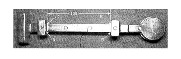
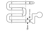
これらの試料を用いて、表2に示す4種類の鋳造条件で図1に示す形状の試験片1を鋳造し、割れ性の実験を行った。図1の試験片1は平行部の長さが105mmであり、拘束端部の角部Rは曲率半径0mmである。割れについては、目視及びカラーチェックによってチェックした。割れ性の評価は、割れ率により算出した。
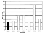
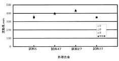
図2は、各成分が割れに及ぼす影響を検証するために、試料1乃至試料5を条件1乃至4で鋳造し、それぞれの試験片1の割れ性をグラフ化したものである。表2の条件1の結果は斜線、条件2の結果は白塗り、条件3の結果は黒塗り、条件4の結果は灰色で示されている。試料1(特開2001−316752の合金−1)と試料3(特開2001−316752の合金−2)は条件3及び条件4において割れ性が50%と高い割合で割れが発生している。これは、Snの添加がなされていないことが原因と考えられる。一方、Snが添加されている試料2、試料4(特開2004−238676の合金)と試料5(本実施の形態のマグネシウム合金−1)を比較すると、試料5(本実施の形態のマグネシウム合金−1)ではすべての条件において割れ性が30%以下となっている。これは、Naの元素添加の効果と考えられる。よって、0.05%のNaの添加は割れに対して効果が認められる。
FIG. 2 is a graph in which the cracking properties of each
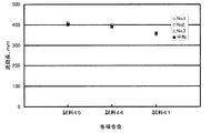
図3は、Sn濃度の割れ性への影響を検証するために、本実施の形態のマグネシウム合金をベースとしてSnの添加量を変化させた試験片1の割れ性をグラフ化したものである。表2の条件1の結果は斜線、条件2の結果は白塗り、条件3の結果は黒塗り、条件4の結果は灰色で示されている。全ての試験片において、条件1は割れ性が低く条件3及び4は割れ性が高いという結果となった。また、試料6(0.1%Sn)、試料7(本実施の形態のマグネシウム合金−2 0.8%Sn)、試料8(本実施の形態のマグネシウム合金−3 1.5%Sn)においては、割れ性への効果が認められたが、試料9(2.0%Sn)では割れが発生しやすい結果となった。このことから、Sn添加量は1.5%以下とするのが好ましく、Snを1.5%以下とした本実施の形態のマグネシウム合金においては、割れ性は低い結果となった。
FIG. 3 is a graph showing the crackability of the
図4は、Ca成分の割れ性への影響を検証するために、本実施の形態のマグネシウム合金をベースとしてCaの添加量を変化させた試験片1の割れ性をグラフ化したものである。表2の条件1の結果は斜線、条件2の結果は白塗り、条件3の結果は黒塗り、条件4の結果は灰色で示されている。試料10(本実施の形態のマグネシウム合金−4 0.3Ca)及び試料11(本実施の形態のマグネシウム合金−5 1.5%Ca)については、割れ性が40%以下となっている。一方、試料12(2.0%Ca)及び試料13(2.5%Ca)では、全ての条件において割れ性が40%以上でありCa量が多くなるに従って、割れ性が増加する。特に、2.0%以上添加した場合には割れ性が増加している。Caを1.9%以下とした本実施の形態のマグネシウム合金においては、割れ性は低い結果となった。
FIG. 4 is a graph of the crackability of the
(実験2)
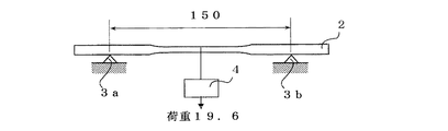
本発明の実施の形態の合金と比較材料について耐クリープ性の実験を行った。250℃の温度雰囲気で43時間曲げ加重を負荷する耐クリープ性実験Iと200℃の温度雰囲気で100時間曲げ加重を負荷する耐クリープ性実験IIとを行いそれぞれ変位を測定した。耐クリープ性実験Iでは、試料14(本実施の形態のマグネシウム合金−6)、試料15、試料16、試料17(特開2004−238676の合金−2)、試料18(AZ91D−1)及び試料19(ADC12)を用いて図5Aに示す試験片2を鋳造した。耐クリープ性実験IIでは、試料14(本実施の形態のマグネシウム合金−6)、試料20(本実施の形態のマグネシウム合金−7)、試料15、試料16、試料17(特開2004−238676の合金−2)、試料21、試料22、試料19(ADC12)を用いて図5−1に示す試験片2を鋳造した。試験片2は、ASTMのB−85の引張試験片(平行部の直径6.35mm、標点間距離57.5mm、長さ210mm)であり、図5−2で示されるように、試験片2の両端を支持台3a、3bにて支持し、支持台3aと3bの間の距離は150mmとし、試験片2の中央部に19.6Nの荷重を所定の時間かけ、試験片2に曲げ変位を生じさせた。
Experiments on creep resistance were performed on the alloy and the comparative material of the embodiment of the present invention. Displacement was measured by conducting a creep resistance experiment I in which a bending load was applied for 43 hours in a temperature atmosphere of 250 ° C. and a creep resistance experiment II in which a bending load was applied for 100 hours in a temperature atmosphere of 200 ° C. In the creep resistance experiment I, Sample 14 (magnesium alloy-6 of the present embodiment), Sample 15, Sample 16, Sample 17 (Alloy-2 of JP-A-2004-238676), Sample 18 (AZ91D-1), and Sample 19 (ADC12) was used to cast a
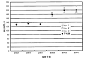
図6は耐クリープ性実験Iの結果、図7は耐クリープ性実験IIの結果を示している。本実施の形態のマグネシウム合金は黒塗り、比較材料は白塗りで示す。図6より、試料14(本実施の形態のマグネシウム合金−6)は、試料17(特開2004−238676の合金−2)と比較して優れた結果となっている。これは、Na添加によるSn−Na化合物の晶出によると考えられる。 6 shows the results of creep resistance experiment I, and FIG. 7 shows the results of creep resistance experiment II. The magnesium alloy of this embodiment is shown in black, and the comparative material is shown in white. From FIG. 6, sample 14 (magnesium alloy-6 of the present embodiment) is superior to sample 17 (alloy-2 of JP-A-2004-238676). This is considered to be due to crystallization of the Sn—Na compound by addition of Na.
図7において、試料14(本実施の形態のマグネシウム合金−6)及び試料20(本実施の形態のマグネシウム合金−7)は他の比較材料と比べても歪みが小さく、試料19(ADC12)とほぼ同程度の耐クリープ性を示している。本実施の形態のマグネシウム合金は、マグネシウム合金では困難だと考えられているアルミダイカスト合金並み、また同程度に近い耐クリープ性を得ている。 In FIG. 7, sample 14 (magnesium alloy-6 of the present embodiment) and sample 20 (magnesium alloy-7 of the present embodiment) are less distorted than other comparative materials, and sample 19 (ADC12) and It shows almost the same creep resistance. The magnesium alloy of the present embodiment has a creep resistance close to or comparable to that of an aluminum die cast alloy that is considered difficult with a magnesium alloy.
(実験3)
本発明の実施の形態の合金と比較材料について、塩水噴霧試験(JISZ2371)により耐食性の実験を行った。実験に用いた合金の種類及び腐食率を表4に示す。試料23は本実施の形態のマグネシウム合金−8、試料25は特開2004−238676の合金−3、試料26はSnの添加質量%が本実施の形態の範囲外である合金、試料27はAZ91D−2、試料29は特開2001−316752の合金−3となる。
For the alloy and the comparative material of the embodiment of the present invention, an experiment on corrosion resistance was conducted by a salt spray test (JISZ2371). Table 4 shows the types and corrosion rates of the alloys used in the experiment. Sample 23 is magnesium alloy-8 of the present embodiment, sample 25 is alloy-3 of JP-A-2004-238676, sample 26 is an alloy in which the added mass% of Sn is outside the range of the present embodiment, and sample 27 is AZ91D -2 and sample 29 are alloy-3 of JP-A-2001-316752.
図8に実験3の結果を本実施の形態のマグネシウム合金を黒塗り、比較材料を白塗りで示す。塩水噴霧試験の実施結果から、試料23(本実施の形態のマグネシウム合金−8)の耐食性は試料27(AZ91D−2)と同程度であり、試料25(特開2004−238676の合金−3)及びその他の比較材料よりも優れた耐食性を示した。一般にSnを添加すると耐食性が低下することが知られているが、試料23(本実施の形態のマグネシウム合金−8)の耐食性は試料27(AZ91D−2)と同程度であり耐食性の低下は見られなかった。これは、本実施の形態のSnの添加範囲においては、Mgマトリックス中にSnが固溶して固溶体を形成することにより、Mgマトリックス総体の電位が上がり、Mgマトリックスと金属間化合物などの析出物との電位差が少なくなり、局部腐食が促進されなくなるためだと考えられる。また、Mgに対するSnの固溶域が広い高温からダイカストを急冷することにより、耐食性に影響しない固溶体、又は多少は耐食性に効果がある固溶体が得られ、かつ耐食性を低下させる金属間化合物などの析出があまり生成されないことが考えられる。しかし、Snの添加量が多い試料25(特開2004−238676の合金−3)、試料26、試料28においては、耐食性が低下した。これは耐食性に悪影響を及ぼす金属間化合物が晶出するためと考えられる。
FIG. 8 shows the results of
(実験4)
Mg合金の溶解、鋳造時のMg合金溶湯の防燃性は、鋳造性、生産性に影響を及ぼす不可欠の要素である。防燃効果の無い合金は、鋳造温度を上げることができないため、湯流れ不良や充填不良が発生する。特に、Mg合金は鋳造温度の影響が大きいため、防燃効果は不可欠である。溶湯温度の制御可能な温度目安は、680℃から730℃程度でこれ以上の溶湯温度で鋳造すると、インゴット投入時などで着火して燃焼反応し、燃焼を制御できなくなる。
(Experiment 4)
Melting of the Mg alloy and flame retardancy of the molten Mg alloy during casting are indispensable factors that affect the castability and productivity. An alloy that does not have a flameproofing effect cannot raise the casting temperature, thus causing poor hot-water flow and poor filling. In particular, the Mg alloy has a great influence on the casting temperature, so the flameproofing effect is indispensable. If the molten metal temperature is about 680 ° C. to 730 ° C. and cast at a molten metal temperature higher than this, the molten metal ignites and reacts when the ingot is charged, and the combustion cannot be controlled.
(実験4−1)
本実施の形態のマグネシウム合金と比較材料についての防燃性の評価を行った。実験方法は、700℃に溶湯温度を保持して表面の酸化物を除去し、10分間沈静した後、蓋を開けて着火時間を測定するというものである。実験に用いた合金の種類を表5に示す。表6の着火時間は、着火が2箇所になった時の時間を測定したものである。試料32は特開2004−238676の合金−4、試料33は本実施の形態のマグネシウム合金−9、試料34はAM60Bである。
Flame retardant evaluation was performed on the magnesium alloy and the comparative material of the present embodiment. The experimental method is to maintain the molten metal temperature at 700 ° C. to remove surface oxides, settle for 10 minutes, then open the lid and measure the ignition time. Table 5 shows the types of alloys used in the experiment. The ignition time in Table 6 is obtained by measuring the time when the ignition is at two places. Sample 32 is alloy-4 of JP-A-2004-238676,
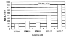
図9及び表6に実験の結果を示す。試料33(本実施の形態のマグネシウム合金−9)では、試料30、試料31、試料32(特開2004−238676)と比較して着火時間が20秒以上長く、防燃性が認められた。これは、Mg溶湯表面にNaの比較的安定な防護皮膜が発生したことによる。
FIG. 9 and Table 6 show the results of the experiment. In sample 33 (magnesium alloy-9 of the present embodiment), the ignition time was 20 seconds or longer as compared with
(実験4−2)
次に各Na成分の防燃性に及ぼす影響について調査を行った。実験4−1と同様の方法で、表7に示す合金について実験を行った。試料36は特開2004−23876の合金−4、試料38は本実施の形態のマグネシウム合金−10、試料39は本実施の形態のマグネシウム合金−11、試料40は本実施の形態のマグネシウム合金−12となる。
Next, the effect of each Na component on the flame retardancy was investigated. Experiments were conducted on the alloys shown in Table 7 in the same manner as in Experiment 4-1. Sample 36 is alloy-4 of JP-A-2004-23876, sample 38 is magnesium alloy-10 of the present embodiment, sample 39 is magnesium alloy-11 of the present embodiment, and
その結果を図10及び表8に示す。試料37(Na0.009%)と試料38(本実施の形態のマグネシウム合金−10 Na0.03%)との比較から、Na成分が0.009%程度では効果が無いが、0.03%程度になると効果が認められた。0.009%Na添加量では、効果が少なく着火時間は比較材料と同程度である。試料39(本実施の形態のマグネシウム合金−11 Na0.2%)及び試料40(本実施の形態のマグネシウム合金−12 Na0.5%)から、Naは成分量が多いと、さらに防燃効果が認められる。ただ、Na添加量が多いと耐食性や引張特性に悪影響を及ぼすことから上限は0.5%程度が適当である。 The results are shown in FIG. From a comparison between sample 37 (Na 0.009%) and sample 38 (magnesium alloy of the present embodiment-10 Na 0.03%), there is no effect when the Na component is about 0.009%, but the effect is obtained when it is about 0.03%. Admitted. When 0.009% Na is added, the effect is small and the ignition time is comparable to that of the comparative material. From sample 39 (magnesium alloy-11 Na 0.2% in this embodiment) and sample 40 (magnesium alloy-12 Na 0.5% in this embodiment), if the amount of Na is large, the flame retardant effect is further increased. Is recognized. However, if the amount of Na added is large, the corrosion resistance and tensile properties are adversely affected, so an upper limit of about 0.5% is appropriate.
(実験4−3)
Na添加により防燃効果が向上するが、さらにAl成分を増加させることによって防燃効果は向上する。特に、Alが多いほど効果が大きい。よってAlの添加量を変化させた表9に示す合金について実験を行った。試料41は本実施の形態のマグネシウム合金−13、試料42は本実施の形態のマグネシウム合金−14、試料43は特開2004−238676の合金−5、試料44本実施の形態のマグネシウム合金−15、試料45は本実施の形態のマグネシウム合金−16となる。
Although the flameproofing effect is improved by adding Na, the flameproofing effect is improved by further increasing the Al component. In particular, the more Al, the greater the effect. Therefore, experiments were conducted on alloys shown in Table 9 in which the amount of Al added was changed. Sample 41 is magnesium alloy-13 of the present embodiment, sample 42 is magnesium alloy-14 of the present embodiment, sample 43 is alloy-5 of JP-A-2004-238676, sample 44 is magnesium alloy-15 of the present embodiment. Sample 45 is the magnesium alloy-16 of the present embodiment.
図11及び表10に実験の結果を示す。実験4−1から、本実施の形態のマグネシウム合金は、いずれの比較材料と比較しても防燃性は良く、図11より試料43(特開2004−238676の合金−5)と本実施の形態のマグネシウム合金との差は明確である。また、試料41(本実施の形態のマグネシウム合金−13 Al6.5%)と比べて試料44(本実施の形態のマグネシウム合金−15 Al8.0%)及び試料45(本実施の形態のマグネシウム合金−16 Al9.0%)は防燃性が良いことから、Al成分を増加させると防燃効果が向上することがわかる。これは, Al添加によりスピネルやアルミナ皮膜が溶湯表面に発生するためである。これらの皮膜は安定で、表面のMgO化を制御することができる。ただ、Al添加により鋳造性などが向上するが、耐クリープ性が低下する。試料43(特開2004−238676の合金−5)はNaが添加されていないため本実施の形態のマグネシウム合金と比較すると防燃性が低い。本実施の形態のマグネシウム合金の防燃性が良いのは、Naを添加するとMg溶湯表面にNa酸化物が生じ、Alとの相乗効果により安定な皮膜が生成し、防燃性が向上するためである。 FIG. 11 and Table 10 show the results of the experiment. From Experiment 4-1, the magnesium alloy of this embodiment has good flameproofing properties compared to any of the comparative materials. From FIG. 11, sample 43 (Japanese Unexamined Patent Application Publication No. 2004-238676 Alloy-5) and this embodiment The difference from the form of magnesium alloy is clear. Further, compared with sample 41 (magnesium alloy of the present embodiment-13 Al 6.5%), sample 44 (magnesium alloy of the present embodiment-15 Al 8.0%) and sample 45 (magnesium alloy of the present embodiment). -16 Al9.0%) has good flameproofing properties, it can be seen that increasing the Al component improves the flameproofing effect. This is because spinel and alumina film are generated on the surface of the molten metal due to the addition of Al. These films are stable and can control the formation of MgO on the surface. However, although the castability and the like are improved by the addition of Al, the creep resistance is lowered. Sample 43 (Alloy-5 of JP-A-2004-238676) does not contain Na and therefore has lower flame retardancy than the magnesium alloy of the present embodiment. The reason why the magnesium alloy of the present embodiment has good flame retardancy is that when Na is added, Na oxide is generated on the surface of the molten Mg, and a stable film is formed due to a synergistic effect with Al, thereby improving the flame retardancy. It is.
(実験5)
本実施の形態のマグネシウム合金と比較材料についての引張特性の調査を行った。表11に示す金属について実験を行った。試料46は本実施の形態のマグネシウム合金−17、試料47は本実施の形態のマグネシウム合金−18、試料48は本実施の形態のマグネシウム合金−19、試料49は特開2004−238676の合金−6、試料50はADC12となる。
The tensile characteristics of the magnesium alloy of this embodiment and the comparative material were investigated. Experiments were performed on the metals shown in Table 11. Sample 46 is magnesium alloy-17 of the present embodiment, sample 47 is magnesium alloy-18 of the present embodiment, sample 48 is magnesium alloy-19 of the present embodiment, and sample 49 is an alloy of Japanese Patent Application Laid-Open No. 2004-238676. 6.
結果を表12及び図12に示す。図12において、引張強さを斜線、耐力を白塗り、比強度を黒塗り、比耐力を灰色とする。Alの質量%が増加するにしたがって、引張強さ、耐力が増加する。特に耐力が増加し、試料48(本実施の形態のマグネシウム合金−19 Al9.5%)は試料50(ADC12)並の耐力値が認められた。また、比強度、比耐力においては試料46(本実施の形態のマグネシウム合金−17)、試料47(本実施の形態のマグネシウム合金−18)及び試料48(本実施の形態のマグネシウム合金−19)は試料50(ADC12)合金より高い値を示している。また、それらと試料49(特開2004−238676の合金−6)とを比較しても僅かに高い値を示している。Al%を調節することにより、高強度、高耐力が得られるが、耐クリープ性は低下する。 The results are shown in Table 12 and FIG. In FIG. 12, the tensile strength is hatched, the proof stress is white, the specific strength is black, and the specific strength is gray. As the mass% of Al increases, the tensile strength and proof stress increase. In particular, the proof stress increased, and the proof stress of Sample 48 (magnesium alloy-19Al9.5% of this embodiment) was the same as that of Sample 50 (ADC12). Further, in terms of specific strength and specific proof stress, sample 46 (magnesium alloy-17 of the present embodiment), sample 47 (magnesium alloy-18 of the present embodiment) and sample 48 (magnesium alloy-19 of the present embodiment). Indicates a higher value than the sample 50 (ADC12) alloy. Further, even when they are compared with the sample 49 (Alloy-6 of JP-A-2004-238676), a slightly higher value is shown. By adjusting Al%, high strength and high yield strength can be obtained, but the creep resistance decreases.
(実験6)
本発明の実施の形態のマグネシウム合金と比較材料について防振性の実験を行った。防振性は、振動や音に対して影響を及ぼすことから、実際の製品に導入された場合は重要な特性である。試料1(特開2001−316752の合金−1)、試料4(特開2004−238676の合金)、試料5(本実施の形態のマグネシウム合金−1)、試料27(AZ91D−2)、試料19(ADC12)について実験を行った。図13の試験片を用いて防振性の評価を行った。ハンマ-で冶具ヘッドに入力を与えて固定振動数を求め,対数減衰率を以下の式を用いて計算した。
式(1)において、fnは1次固有振動数、ΔXは時間変化量、ΔYは変化量である。
(Experiment 6)
An experiment on vibration isolation was conducted on the magnesium alloy and the comparative material of the embodiment of the present invention. Anti-vibration properties affect vibration and sound, and are important characteristics when introduced into actual products. Sample 1 (Alloy-1 of JP-A-2001-316752), Sample 4 (Alloy of JP-A-2004-238676), Sample 5 (Magnesium Alloy-1 of the present embodiment), Sample 27 (AZ91D-2), Sample 19 Experiments were performed on (ADC12). The vibration resistance was evaluated using the test piece of FIG. A fixed frequency was obtained by applying input to the jig head with a hammer, and the logarithmic damping rate was calculated using the following formula.
In equation (1), fn is the primary natural frequency, ΔX is the amount of change over time, and ΔY is the amount of change.
図14に防振性の実験の結果を示す。本実施の形態のマグネシウム合金は黒塗り、比較材料は白塗りで示す。一般的に、マグネシウム合金はアルミニウム合金と比較すると防振性は優れている。本実験においても、試料19(ADC12)のアルミニウム合金と比較するといずれのマグネシウム合金の防振性は高い結果となった。また、マグネシウム合金の防振性は合金系によって異なるが、試料27(AZ91D−2)のMg−Al−Zn系合金と比較すると、本実施の形態のマグネシウム合金を含むMg−Al−Ca系合金は防振性に優れた結果となった。本実施の形態のマグネシウム合金である試料5(本実施の形態のマグネシウム合金−1)は最も優れた防振効果を有する。同じMg−Al−Ca系合金である試料1(特開2001−316752の合金−1)や試料4(特開2004−238676の合金)と比較してもより高い防振効果が得ることができたのは、Sn添加とNa添加により、双晶変形し易くなったためである。 FIG. 14 shows the results of the vibration isolation experiment. The magnesium alloy of this embodiment is shown in black, and the comparative material is shown in white. In general, a magnesium alloy is superior in vibration proofing properties as compared with an aluminum alloy. Also in this experiment, as compared with the aluminum alloy of Sample 19 (ADC12), the vibration-proof property of any magnesium alloy was high. Moreover, although the vibration-proof property of a magnesium alloy changes with alloy systems, compared with the Mg-Al-Zn type alloy of the sample 27 (AZ91D-2), the Mg-Al-Ca type alloy containing the magnesium alloy of this Embodiment The result was excellent in vibration proofing. Sample 5 (magnesium alloy-1 of the present embodiment), which is the magnesium alloy of the present embodiment, has the most excellent anti-vibration effect. Compared with Sample 1 (Alloy-1 of JP-A-2001-316752) and Sample 4 (Alloy of JP-A-2004-238676), which are the same Mg—Al—Ca-based alloys, a higher vibration isolation effect can be obtained. This is because twin deformation is easily caused by addition of Sn and addition of Na.
(実験7)
図5−1に示す試験片にて、試料5(本実施の形態のマグネシウム合金−1)、試料47(本実施の形態のマグネシウム合金−18)、試料1(特開2001−316752の合金−1)、試料27(AZ91D−2)、及び試料50(ADC12)について引張特性の調査を行った。
(Experiment 7)
5-1, sample 5 (magnesium alloy-1 of the present embodiment), sample 47 (magnesium alloy-18 of the present embodiment), sample 1 (alloy of JP 2001-316752-). 1), Sample 27 (AZ91D-2), and Sample 50 (ADC12) were examined for tensile properties.
結果を図15に示す。図15において、引張強さを斜線、耐力を白塗りとし、破断伸びを折れ線グラフで示す。試料5(本実施の形態のマグネシウム合金−1)及び試料47(本実施の形態のマグネシウム合金−18)の引張特性は、代表的なマグネシウム合金である試料27(AZ91D−2)と比較すると同等か、それ以上である。より具体的には、Alの添加量が8.0質量%以上である場合に試料27よりも優れた引張特性を示している。この傾向はAlの添加量の増大に伴い、より顕著なものとなる。 The results are shown in FIG. In FIG. 15, the tensile strength is hatched, the proof stress is white, and the breaking elongation is shown by a line graph. The tensile properties of sample 5 (magnesium alloy-1 of the present embodiment) and sample 47 (magnesium alloy-18 of the present embodiment) are equivalent to those of sample 27 (AZ91D-2), which is a typical magnesium alloy. Or more. More specifically, tensile properties superior to those of the sample 27 are shown when the amount of Al added is 8.0% by mass or more. This tendency becomes more remarkable as the amount of Al added increases.
(実験8)
図16に示す湯流れ試験片を用いて表13に示す条件で、試料5(本実施の形態のマグネシウム合金−1、Al6.5%)、試料47(本実施の形態のマグネシウム合金−18 Al8.5%)、試料27(AZ91D−2)、試料37について湯流れ試験を実施した。
Sample 5 (magnesium alloy-1 of the present embodiment, Al 6.5%), sample 47 (magnesium alloy of the present embodiment-18 Al8) under the conditions shown in Table 13 using the molten metal flow test piece shown in FIG. 0.5%), Sample 27 (AZ91D-2), and Sample 37 were subjected to a hot water flow test.
その結果を図17に示す。試料5(本実施の形態のマグネシウム合金−1、Al6.5%)及び試料47(本実施の形態のマグネシウム合金−18 Al8.5%)は、試料37と同程度の湯流れ性が認められた。さらに、本実施の形態のマグネシウム合金であっても試料5よりAlの添加量が8.5%である試料47のほうが、より優れた湯流れ性が得られた。
The result is shown in FIG. Sample 5 (magnesium alloy-1 of the present embodiment, Al 6.5%) and sample 47 (magnesium alloy of the present embodiment-18 Al 8.5%) have the same hot water flow properties as sample 37. It was. Furthermore, even in the case of the magnesium alloy of the present embodiment, the sample 47 in which the added amount of Al is 8.5% is more excellent than that of the
(実験9)
実験8と同様の条件にて試料45(本実施の形態のマグネシウム合金−16 Al9.0%)、試料44(本実施の形態のマグネシウム合金−15 Al8.0%)、試料41(本実施の形態のマグネシウム合金−13 Al6.5%)についてさらに湯流れ試験を実施した。
(Experiment 9)
Sample 45 (magnesium alloy-16Al9.0% in this embodiment), sample 44 (magnesium alloy-15Al8.0% in this embodiment), sample 41 (this embodiment under the same conditions as in Experiment 8) A hot water flow test was further conducted on the magnesium alloy in the form-13 Al 6.5%.
その結果を図18に示す。Alの添加量が増加するに伴い、湯流れ性が向上している。具体的には、Al添加量が8.0%以上となると優れた湯流れ性を得ることができる。この理由は、液相温度と固相温度がAlの添加量の増加に伴い低下するためと考えられる。 The result is shown in FIG. As the amount of Al added increases, the hot water flow is improved. Specifically, when the Al addition amount is 8.0% or more, excellent hot water flowability can be obtained. The reason for this is thought to be that the liquid phase temperature and the solid phase temperature decrease as the amount of Al added increases.
(実験10)
実験2にて行った耐クリープ性の試験を、250℃の雰囲気で50時間曲げ加重を負荷することにより行った。カルシウム添加量を変化させた試料51(Ca0.3%)、試料52(Ca1.3%)、試料53(Ca1.9%)について試験を行った。
The creep resistance test performed in
その結果を図19に示す。Caを1.3%以上とした試料はCaを0.3%とした試料よりも耐クリープ性が優れた結果となった。従って、Caの添加量は1.3〜1.9質量%であることが望ましい。 The result is shown in FIG. The sample with Ca of 1.3% or more resulted in better creep resistance than the sample with Ca of 0.3%. Therefore, the addition amount of Ca is desirably 1.3 to 1.9% by mass.
(実験11)
次に、本実施の形態のマグネシウム合金と表15に示す合金及び試料27とを接触させて塩水噴霧試験(JISZ2371)を行い、100時間後の腐食率を測定した。
Next, the magnesium alloy of this embodiment, the alloy shown in Table 15 and the sample 27 were brought into contact with each other, a salt spray test (JISZ2371) was performed, and the corrosion rate after 100 hours was measured.
その結果を図20に示す。接触腐食は合金成分によって異なるが、試料54、55、56のアルミニウム材料が効果的で、腐食率が小さい結果となった。本発明による耐クリープマグネシウム合金は、上述した実施の形態に限定されず、特許請求の範囲に記載した範囲で種々の変形や改良が可能である。 The result is shown in FIG. Although the contact corrosion differs depending on the alloy components, the aluminum materials of Samples 54, 55, and 56 were effective, resulting in a low corrosion rate. The creep-resistant magnesium alloy according to the present invention is not limited to the above-described embodiment, and various modifications and improvements can be made within the scope described in the claims.
本発明の耐クリープマグネシウム合金は、自転車用部品の素材に使用される合金として利用することができる。 The creep-resistant magnesium alloy of the present invention can be used as an alloy used as a material for bicycle parts.
1:試験片1、 2:試験片2、 3a:支持台、 3b:支持台
1:
Claims (3)
Priority Applications (1)
| Application Number | Priority Date | Filing Date | Title |
|---|---|---|---|
| JP2009123515A JP5383314B2 (en) | 2008-06-25 | 2009-05-21 | Creep-resistant magnesium alloy |
Applications Claiming Priority (3)
| Application Number | Priority Date | Filing Date | Title |
|---|---|---|---|
| JP2008166576 | 2008-06-25 | ||
| JP2008166576 | 2008-06-25 | ||
| JP2009123515A JP5383314B2 (en) | 2008-06-25 | 2009-05-21 | Creep-resistant magnesium alloy |
Publications (2)
| Publication Number | Publication Date |
|---|---|
| JP2010031357A true JP2010031357A (en) | 2010-02-12 |
| JP5383314B2 JP5383314B2 (en) | 2014-01-08 |
Family
ID=41736175
Family Applications (1)
| Application Number | Title | Priority Date | Filing Date |
|---|---|---|---|
| JP2009123515A Active JP5383314B2 (en) | 2008-06-25 | 2009-05-21 | Creep-resistant magnesium alloy |
Country Status (1)
| Country | Link |
|---|---|
| JP (1) | JP5383314B2 (en) |
Cited By (4)
| Publication number | Priority date | Publication date | Assignee | Title |
|---|---|---|---|---|
| JP2014535005A (en) * | 2011-10-20 | 2014-12-25 | ポステク アカデミー−インダストリー ファウンデイションPostech Academy−Industry Foundation | Non-heat-treatable magnesium alloy sheet with excellent room temperature formability that minimizes segregation |
| JP2017160542A (en) * | 2017-04-28 | 2017-09-14 | 住友電気工業株式会社 | Magnesium alloy casting material, magnesium alloy cast coil material, wrought magnesium alloy material, magnesium alloy member, magnesium alloy joint material, and method for producing magnesium alloy casting material |
| CN107236884A (en) * | 2017-06-07 | 2017-10-10 | 四川理工学院 | High-strength corrosion-resistant wrought magnesium alloy and preparation method thereof |
| CN113005346A (en) * | 2021-02-23 | 2021-06-22 | 吉林大学 | Corrosion-resistant fast extrusion magnesium alloy and preparation method thereof |
Citations (6)
| Publication number | Priority date | Publication date | Assignee | Title |
|---|---|---|---|---|
| JPS61264141A (en) * | 1985-05-17 | 1986-11-22 | Tsuneaki Mori | Magnesium casting method |
| JP2004238676A (en) * | 2003-02-05 | 2004-08-26 | Dead Sea Magnesium Ltd | Magnesium alloy |
| JP2005068550A (en) * | 2003-08-06 | 2005-03-17 | Aisin Seiki Co Ltd | Inexpensive heat resistant magnesium alloy for casting having excellent heat resistance and casting property |
| JP2006070303A (en) * | 2004-08-31 | 2006-03-16 | Takata Corp | Magnesium alloy for die casting and magnesium die-cast product using the same |
| JP2006291327A (en) * | 2005-04-14 | 2006-10-26 | Mitsubishi Alum Co Ltd | Heat-resistant magnesium alloy casting |
| JP2007138227A (en) * | 2005-11-16 | 2007-06-07 | Sumitomo Electric Ind Ltd | Magnesium alloy material |
-
2009
- 2009-05-21 JP JP2009123515A patent/JP5383314B2/en active Active
Patent Citations (6)
| Publication number | Priority date | Publication date | Assignee | Title |
|---|---|---|---|---|
| JPS61264141A (en) * | 1985-05-17 | 1986-11-22 | Tsuneaki Mori | Magnesium casting method |
| JP2004238676A (en) * | 2003-02-05 | 2004-08-26 | Dead Sea Magnesium Ltd | Magnesium alloy |
| JP2005068550A (en) * | 2003-08-06 | 2005-03-17 | Aisin Seiki Co Ltd | Inexpensive heat resistant magnesium alloy for casting having excellent heat resistance and casting property |
| JP2006070303A (en) * | 2004-08-31 | 2006-03-16 | Takata Corp | Magnesium alloy for die casting and magnesium die-cast product using the same |
| JP2006291327A (en) * | 2005-04-14 | 2006-10-26 | Mitsubishi Alum Co Ltd | Heat-resistant magnesium alloy casting |
| JP2007138227A (en) * | 2005-11-16 | 2007-06-07 | Sumitomo Electric Ind Ltd | Magnesium alloy material |
Cited By (5)
| Publication number | Priority date | Publication date | Assignee | Title |
|---|---|---|---|---|
| JP2014535005A (en) * | 2011-10-20 | 2014-12-25 | ポステク アカデミー−インダストリー ファウンデイションPostech Academy−Industry Foundation | Non-heat-treatable magnesium alloy sheet with excellent room temperature formability that minimizes segregation |
| JP2017160542A (en) * | 2017-04-28 | 2017-09-14 | 住友電気工業株式会社 | Magnesium alloy casting material, magnesium alloy cast coil material, wrought magnesium alloy material, magnesium alloy member, magnesium alloy joint material, and method for producing magnesium alloy casting material |
| CN107236884A (en) * | 2017-06-07 | 2017-10-10 | 四川理工学院 | High-strength corrosion-resistant wrought magnesium alloy and preparation method thereof |
| CN113005346A (en) * | 2021-02-23 | 2021-06-22 | 吉林大学 | Corrosion-resistant fast extrusion magnesium alloy and preparation method thereof |
| CN113005346B (en) * | 2021-02-23 | 2022-02-11 | 吉林大学 | Corrosion-resistant fast extrusion magnesium alloy and preparation method thereof |
Also Published As
| Publication number | Publication date |
|---|---|
| JP5383314B2 (en) | 2014-01-08 |
Similar Documents
| Publication | Publication Date | Title |
|---|---|---|
| US8574382B2 (en) | Heat-resistant aluminium alloy | |
| JP4539572B2 (en) | Magnesium alloys and castings for casting | |
| US20170121793A1 (en) | Aluminum alloy for die casting, and aluminum alloy die cast produced using same | |
| JP5703881B2 (en) | High strength magnesium alloy and method for producing the same | |
| JP2012087352A (en) | Method of manufacturing magnesium alloy cast | |
| JP2009013480A (en) | Casting aluminum alloy, and cylinder head for internal combustion engine | |
| KR20070102952A (en) | Magnesium alloys | |
| JP2006291327A (en) | Heat-resistant magnesium alloy casting | |
| JP5383314B2 (en) | Creep-resistant magnesium alloy | |
| EP1241276A1 (en) | Creep-resistant magnesium alloy | |
| JP4202298B2 (en) | Heat-resistant magnesium alloy for die casting and die-cast products of the same alloy | |
| JP5969713B1 (en) | Aluminum alloy for die casting and aluminum alloy die casting using the same | |
| RU2745595C1 (en) | Cast aluminum alloy | |
| WO2005118900A1 (en) | Creep-resistant magnesium alloy | |
| JP2005187896A (en) | Heat resistant magnesium alloy casting | |
| JP2005240129A (en) | Heat resistant magnesium alloy casting | |
| JP2003027169A (en) | Aluminum alloy and aluminum alloy casting | |
| JP4526769B2 (en) | Magnesium alloy | |
| JP5852039B2 (en) | Heat-resistant magnesium alloy | |
| JP5590413B2 (en) | High thermal conductivity magnesium alloy | |
| JP7472318B2 (en) | Aluminum alloys and aluminum alloy castings | |
| JP7462190B2 (en) | Flame-retardant and highly tough magnesium alloy | |
| JP2005187895A (en) | Heat resistant magnesium alloy casting | |
| JP2013174022A (en) | Aluminum alloy for casting and aluminum alloy casting | |
| JP2011219820A (en) | Heat resisting magnesium alloy |
Legal Events
| Date | Code | Title | Description |
|---|---|---|---|
| A621 | Written request for application examination |
Free format text: JAPANESE INTERMEDIATE CODE: A621 Effective date: 20120406 |
|
| A977 | Report on retrieval |
Free format text: JAPANESE INTERMEDIATE CODE: A971007 Effective date: 20130919 |
|
| TRDD | Decision of grant or rejection written | ||
| A01 | Written decision to grant a patent or to grant a registration (utility model) |
Free format text: JAPANESE INTERMEDIATE CODE: A01 Effective date: 20130926 |
|
| A61 | First payment of annual fees (during grant procedure) |
Free format text: JAPANESE INTERMEDIATE CODE: A61 Effective date: 20131001 |
|
| R150 | Certificate of patent or registration of utility model |
Ref document number: 5383314 Country of ref document: JP Free format text: JAPANESE INTERMEDIATE CODE: R150 Free format text: JAPANESE INTERMEDIATE CODE: R150 |