JP2010024120A - Silicon single crystal and its growing method - Google Patents
Silicon single crystal and its growing method Download PDFInfo
- Publication number
- JP2010024120A JP2010024120A JP2008190887A JP2008190887A JP2010024120A JP 2010024120 A JP2010024120 A JP 2010024120A JP 2008190887 A JP2008190887 A JP 2008190887A JP 2008190887 A JP2008190887 A JP 2008190887A JP 2010024120 A JP2010024120 A JP 2010024120A
- Authority
- JP
- Japan
- Prior art keywords
- single crystal
- silicon single
- raw material
- magnetic field
- material melt
- Prior art date
- Legal status (The legal status is an assumption and is not a legal conclusion. Google has not performed a legal analysis and makes no representation as to the accuracy of the status listed.)
- Granted
Links
- 239000013078 crystal Substances 0.000 title claims abstract description 126
- XUIMIQQOPSSXEZ-UHFFFAOYSA-N Silicon Chemical compound [Si] XUIMIQQOPSSXEZ-UHFFFAOYSA-N 0.000 title claims abstract description 93
- 229910052710 silicon Inorganic materials 0.000 title claims abstract description 93
- 239000010703 silicon Substances 0.000 title claims abstract description 93
- 238000000034 method Methods 0.000 title claims abstract description 54
- 239000002994 raw material Substances 0.000 claims abstract description 100
- 239000001301 oxygen Substances 0.000 claims abstract description 65
- 229910052760 oxygen Inorganic materials 0.000 claims abstract description 65
- QVGXLLKOCUKJST-UHFFFAOYSA-N atomic oxygen Chemical compound [O] QVGXLLKOCUKJST-UHFFFAOYSA-N 0.000 claims abstract description 64
- 239000007788 liquid Substances 0.000 claims description 52
- 230000008859 change Effects 0.000 claims description 5
- 230000000694 effects Effects 0.000 description 13
- 239000010453 quartz Substances 0.000 description 9
- VYPSYNLAJGMNEJ-UHFFFAOYSA-N silicon dioxide Inorganic materials O=[Si]=O VYPSYNLAJGMNEJ-UHFFFAOYSA-N 0.000 description 9
- 230000015572 biosynthetic process Effects 0.000 description 7
- 238000007711 solidification Methods 0.000 description 7
- 230000008023 solidification Effects 0.000 description 7
- 235000012431 wafers Nutrition 0.000 description 6
- 230000000052 comparative effect Effects 0.000 description 4
- 238000010586 diagram Methods 0.000 description 4
- 238000009826 distribution Methods 0.000 description 4
- 238000006213 oxygenation reaction Methods 0.000 description 4
- 239000000155 melt Substances 0.000 description 3
- OKTJSMMVPCPJKN-UHFFFAOYSA-N Carbon Chemical compound [C] OKTJSMMVPCPJKN-UHFFFAOYSA-N 0.000 description 2
- 238000005033 Fourier transform infrared spectroscopy Methods 0.000 description 2
- PEDCQBHIVMGVHV-UHFFFAOYSA-N Glycerine Chemical compound OCC(O)CO PEDCQBHIVMGVHV-UHFFFAOYSA-N 0.000 description 2
- 210000000746 body region Anatomy 0.000 description 2
- 238000002109 crystal growth method Methods 0.000 description 2
- 229910002804 graphite Inorganic materials 0.000 description 2
- 239000010439 graphite Substances 0.000 description 2
- 239000011810 insulating material Substances 0.000 description 2
- 230000007246 mechanism Effects 0.000 description 2
- 229910021420 polycrystalline silicon Inorganic materials 0.000 description 2
- 230000008569 process Effects 0.000 description 2
- 230000001105 regulatory effect Effects 0.000 description 2
- 238000010521 absorption reaction Methods 0.000 description 1
- 238000001816 cooling Methods 0.000 description 1
- 230000003247 decreasing effect Effects 0.000 description 1
- 230000007547 defect Effects 0.000 description 1
- 230000003292 diminished effect Effects 0.000 description 1
- 238000010438 heat treatment Methods 0.000 description 1
- 230000006872 improvement Effects 0.000 description 1
- 239000011261 inert gas Substances 0.000 description 1
- 238000004519 manufacturing process Methods 0.000 description 1
- 239000000463 material Substances 0.000 description 1
- 238000002844 melting Methods 0.000 description 1
- 230000008018 melting Effects 0.000 description 1
- 150000002926 oxygen Chemical class 0.000 description 1
- 239000002245 particle Substances 0.000 description 1
- 230000009467 reduction Effects 0.000 description 1
- 230000004044 response Effects 0.000 description 1
- 229910052594 sapphire Inorganic materials 0.000 description 1
- 239000010980 sapphire Substances 0.000 description 1
- 239000004065 semiconductor Substances 0.000 description 1
- 239000007787 solid Substances 0.000 description 1
- 230000001629 suppression Effects 0.000 description 1
- 239000011800 void material Substances 0.000 description 1
Images


Abstract
Description
本発明は、チョクラルスキー法(以下、「CZ法」という)によるシリコン単結晶の育成方法に関し、特に、ルツボ内の原料融液に水平方向の横磁場を印加しつつ、その原料融液からシリコン単結晶を育成する横磁場印加CZ法(以下、「HMCZ法」という)によるシリコン単結晶の育成方法、およびその育成方法によって得られる大口径のシリコン単結晶に関する。 The present invention relates to a method for growing a silicon single crystal by the Czochralski method (hereinafter referred to as “CZ method”), and in particular, while applying a horizontal transverse magnetic field to a raw material melt in a crucible, The present invention relates to a method for growing a silicon single crystal by a lateral magnetic field applied CZ method (hereinafter referred to as “HMCZ method”) for growing a silicon single crystal, and a large-diameter silicon single crystal obtained by the growth method.
通常、CZ法によるシリコン単結晶の育成では、減圧下の不活性ガス雰囲気に維持された引き上げ炉内において、石英ルツボ内に充填された多結晶シリコンなどのシリコン原料を、ルツボを囲繞するヒータにより加熱し溶融させる。石英ルツボ内に原料融液が形成されると、石英ルツボの上方で引き上げ軸に保持された種結晶を下降させ原料融液に浸漬する。この状態から種結晶および石英ルツボを所定の方向に回転させながら種結晶を徐々に上昇させ、これにより、種結晶の下方にシリコン単結晶が育成され引き上げられる。 Usually, in the growth of a silicon single crystal by the CZ method, in a pulling furnace maintained in an inert gas atmosphere under reduced pressure, a silicon raw material such as polycrystalline silicon filled in a quartz crucible is heated by a heater surrounding the crucible. Heat and melt. When the raw material melt is formed in the quartz crucible, the seed crystal held on the pulling shaft is lowered above the quartz crucible and immersed in the raw material melt. From this state, while rotating the seed crystal and the quartz crucible in a predetermined direction, the seed crystal is gradually raised, whereby a silicon single crystal is grown and pulled below the seed crystal.
その際、種結晶の上昇に伴って、種結晶から直径を細く絞られたネック部が育成され、ネック部から所望の直径まで逐次直径を増加させた円錐状のショルダー部が育成される。次いで、シリコンウェーハ用に製品として取り扱われる所望の直径の直胴部が育成され、育成の最終段階で転位の導入を防止するために直胴部から逐次直径を減少させた逆円錐状のテイル部が育成される。 At that time, as the seed crystal rises, a neck portion whose diameter is narrowed from the seed crystal is grown, and a conical shoulder portion whose diameter is successively increased from the neck portion to a desired diameter is grown. Next, a straight barrel portion having a desired diameter to be handled as a product for a silicon wafer is grown, and an inverted conical tail portion in which the diameter is sequentially reduced from the straight barrel portion in order to prevent the introduction of dislocation at the final stage of the growth. Is nurtured.
近年、半導体デバイスのコスト低減および生産性向上の観点からシリコンウェーハの大口径化が図られ、これに対応して、大口径のシリコン単結晶を安定した品質で製造できる技術の確立が急務となっている。 In recent years, the diameter of silicon wafers has been increased from the viewpoint of cost reduction and productivity improvement of semiconductor devices, and in response to this, it is urgently necessary to establish a technology that can produce large-diameter silicon single crystals with stable quality. ing.
ところが、直胴部の直径が300mm以上になる大口径のシリコン単結晶の育成では、育成初期に対応する直胴部の引き上げ方向の上部で酸素濃度が顕著に高くなり、これが問題視されている。この問題は、シリコン単結晶の大口径化に伴って石英ルツボが拡大されるため、単結晶の育成初期に、石英ルツボの内表面と原料融液との接触面積が増加して、ルツボ内表面から原料融液に溶出する酸素の量が増大し、この過量な酸素がシリコン単結晶中に取り込まれることに起因して発生する。 However, in the growth of a large-diameter silicon single crystal in which the diameter of the straight body part is 300 mm or more, the oxygen concentration is remarkably increased at the upper part in the pulling direction of the straight body part corresponding to the initial stage of growth, which is regarded as a problem. . This problem is caused by the fact that the quartz crucible is enlarged as the silicon single crystal is enlarged, so that the contact area between the inner surface of the quartz crucible and the raw material melt increases at the initial stage of the growth of the single crystal. The amount of oxygen eluted from the raw material melt increases, and this excessive amount of oxygen is generated by being taken into the silicon single crystal.
従来から、シリコン単結晶中の酸素濃度の制御は、ルツボの回転速度や引き上げ炉内の圧力を調整することにより行っている。確かに、直胴部の直径が200mm以下である小口径のシリコン単結晶の育成では、ルツボ内表面と原料融液との接触面積が小さく、原料融液に溶出する酸素量が多くないことから、ルツボ回転速度や炉内圧力を調整することで、直胴部の上部の高酸素化を抑制することが可能である。 Conventionally, the oxygen concentration in a silicon single crystal is controlled by adjusting the rotational speed of the crucible and the pressure in the pulling furnace. Certainly, in the growth of a small diameter silicon single crystal having a diameter of the straight body portion of 200 mm or less, the contact area between the inner surface of the crucible and the raw material melt is small, and the amount of oxygen eluted into the raw material melt is not large. By adjusting the crucible rotation speed and the pressure in the furnace, it is possible to suppress the oxygen increase in the upper part of the straight body portion.
上述の通り、大口径のシリコン単結晶の育成では、ルツボ内表面と原料融液との接触面積が大きく、原料融液に溶出する酸素量も多いことから、直胴部の上部の高酸素化を抑制するには、ルツボ回転速度や炉内圧力を大幅に調整しなければならない。この場合、熱環境が大幅に変動するため、シリコン単結晶に有転位化や直径変動が発生するなどし、安定した品質の単結晶を育成することが困難である。特に、原料融液の精密な温度制御のもとで低速引き上げを行い、COP(Cristal Originated Particle)などの空孔欠陥の発生を抑えた低COP単結晶の育成は、著しく困難になる。 As described above, in growing large-diameter silicon single crystals, the contact area between the crucible inner surface and the raw material melt is large, and the amount of oxygen eluted into the raw material melt is large. To suppress this, the crucible rotation speed and furnace pressure must be adjusted significantly. In this case, since the thermal environment fluctuates significantly, dislocations and diameter fluctuations occur in the silicon single crystal, and it is difficult to grow a single crystal of stable quality. In particular, it is extremely difficult to grow a low COP single crystal that is pulled at a low speed under precise temperature control of the raw material melt and suppresses generation of void defects such as COP (Cristal Originated Particle).
一方、HMCZ法によるシリコン単結晶の育成方法は、例えば特許文献1に記載されるように、ルツボを挟んで一対の電磁コイルを対向配置し、その電磁コイルによりルツボ内の原料融液に横磁場を印加しながら単結晶の育成を行う方法であり、横磁場の印加により原料融液の対流を抑制し、変動の少ない熱環境下で単結晶の育成が可能であることから、安定した品質のシリコン単結晶を製造するのに有効な方法とされている。通常、この方法では、結晶成長界面における原料融液の温度変動を抑えるため、横磁場の磁場中心線の位置を原料融液の液面位置と同じ位置に設定し、またはそれよりも下方の原料融液内の位置に設定し、この状態で単結晶の育成を行っている。 On the other hand, as described in Patent Document 1, for example, a method for growing a silicon single crystal by the HMCZ method has a pair of electromagnetic coils opposed to each other with a crucible interposed therebetween, and a transverse magnetic field is applied to the raw material melt in the crucible by the electromagnetic coils. This is a method of growing single crystals while applying sapphire, and by suppressing the convection of the raw material melt by applying a transverse magnetic field, it is possible to grow single crystals in a thermal environment with little fluctuations. This is an effective method for producing silicon single crystals. Normally, in this method, in order to suppress the temperature fluctuation of the raw material melt at the crystal growth interface, the position of the magnetic field center line of the transverse magnetic field is set to the same position as the liquid surface position of the raw material melt, or a lower raw material. The position is set in the melt, and the single crystal is grown in this state.
しかし、このようなHMCZ法を採用しても、上述した直胴部の上部で高酸素化が発生するという問題は解消できない状況であった。 However, even if such an HMCZ method is adopted, the above-described problem of high oxygen generation at the upper portion of the straight body portion cannot be solved.
本発明は、上記の問題に鑑みてなされたものであり、HMCZ法によりシリコン単結晶を育成する際に、横磁場の磁場中心線の位置を適正に調整することにより、直胴部の上部の高酸素化を抑制し、安定した品質のシリコン単結晶を育成することができるシリコン単結晶の育成方法を提供することを目的とする。また、本発明の目的は、大口径で品質の安定したシリコン単結晶を提供することにある。 The present invention has been made in view of the above problems, and when growing a silicon single crystal by the HMCZ method, by appropriately adjusting the position of the magnetic field center line of the transverse magnetic field, An object of the present invention is to provide a method for growing a silicon single crystal that can suppress high oxygenation and grow a silicon single crystal of stable quality. Another object of the present invention is to provide a silicon single crystal having a large diameter and stable quality.
本発明者は、上記目的を達成するため、HMCZ法によりシリコン単結晶を育成することを前提にして鋭意検討を重ね、横磁場の磁場中心線の位置がシリコン単結晶中の酸素濃度に与える影響を詳細に調査した。 In order to achieve the above object, the present inventor has made extensive studies on the assumption that a silicon single crystal is grown by the HMCZ method, and the influence of the position of the magnetic field center line of the transverse magnetic field on the oxygen concentration in the silicon single crystal. Were investigated in detail.
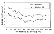
図1は、磁場中心線の位置を原料融液の液面位置と同じ位置に設定して育成を行った単結晶と、液面位置から50mm高い位置に磁場中心線の位置を設定して育成を行った単結晶における引き上げ方向での酸素濃度の分布を示す図である。同図では、液面位置と同じ位置に磁場中心線の位置を設定した場合の結果を丸印で示し、液面位置から50mm高い位置に磁場中心線の位置を設定した場合の結果を三角印で示している。同図に示す結果から、いずれの場合も、単結晶の育成初期に対応する直胴部の上部で酸素濃度が顕著に高くなっているが、液面位置から50mm高い位置に磁場中心線の位置を設定した場合は、液面位置と同じ位置に磁場中心線の位置を設定した場合に比べて、酸素濃度が引き上げ方向全域に亘り低下していることが判明した。 FIG. 1 shows a single crystal grown by setting the position of the magnetic field center line to the same position as the liquid surface position of the raw material melt, and the position of the magnetic field center line is set 50 mm higher than the liquid surface position. It is a figure which shows distribution of the oxygen concentration in the pulling direction in the single crystal which performed. In the figure, the results when the position of the magnetic field center line is set at the same position as the liquid surface position are indicated by circles, and the results when the position of the magnetic field center line is set 50 mm higher than the liquid surface position are indicated by triangles. Is shown. From the results shown in the figure, in each case, the oxygen concentration is remarkably high in the upper portion of the straight body corresponding to the initial stage of single crystal growth, but the position of the magnetic field center line is 50 mm higher than the liquid level. It was found that the oxygen concentration decreased over the entire pulling direction compared to the case where the position of the magnetic field center line was set at the same position as the liquid level.
この事実から、直胴部を育成する際に、横磁場の磁場中心線の位置を、初期には原料融液の液面位置から上方に外れた位置に設定し、育成の途中から原料融液の液面位置と同じ位置、またはそれよりも下方の原料融液内の位置に変更すれば、直胴部の上部の高酸素化を抑制できることを知見した。 From this fact, when cultivating the straight body part, the position of the magnetic field center line of the transverse magnetic field is initially set to a position deviated upward from the liquid surface position of the raw material melt, and the raw material melt is started from the middle of the growth. It has been found that if the position is changed to the same position as the liquid level position in the above, or the position in the raw material melt below that, the high oxygenation in the upper part of the straight body portion can be suppressed.
本発明は、上記の知見に基づいて完成させたものであり、下記(1)のシリコン単結晶の育成方法、および(2)のシリコン単結晶を要旨とする。 The present invention has been completed on the basis of the above findings, and the gist thereof is the following (1) method for growing a silicon single crystal and (2) a silicon single crystal.
(1)ルツボを挟んで一対の電磁コイルを対向配置し、前記電磁コイルによりルツボ内の原料融液に横磁場を印加しつつ、前記原料融液からシリコン単結晶を育成するシリコン単結晶の育成方法において、前記横磁場の磁場中心線の位置を前記原料融液の液面位置よりも高い第1の位置に設定した状態でシリコン単結晶の直胴部の育成を開始し、その後に前記磁場中心線の位置を前記原料融液の液面位置と同じ、またはその液面位置よりも低い第2の位置に変更して前記直胴部の育成を行い、前記直胴部の酸素濃度が7〜14×1017atoms/cm3(ASTM F121−1979)であるシリコン単結晶を育成することを特徴とするシリコン単結晶の育成方法である。 (1) Growing a silicon single crystal from which a pair of electromagnetic coils are opposed to each other with a crucible sandwiched between them and a lateral magnetic field is applied to the raw material melt in the crucible by the electromagnetic coil, and a silicon single crystal is grown from the raw material melt. In the method, the growth of the straight body portion of the silicon single crystal is started in a state where the position of the magnetic field center line of the transverse magnetic field is set to a first position higher than the liquid surface position of the raw material melt, and then the magnetic field The position of the center line is changed to a second position that is the same as or lower than the liquid surface position of the raw material melt, and the straight body portion is grown, so that the oxygen concentration of the straight body portion is 7 A silicon single crystal growth method characterized by growing a silicon single crystal of ˜14 × 10 17 atoms / cm 3 (ASTM F121-1979).
この育成方法において、前記第1の位置から前記第2の位置への前記磁場中心線の位置変更は、シリコン単結晶の育成を開始する前の前記ルツボ内の原料融液量に対してシリコン単結晶の重量の比率が25%以上に達したときに行うことが好ましい。 In this growth method, the change in the position of the magnetic field center line from the first position to the second position is performed by changing the silicon single-crystal amount relative to the amount of the raw material melt in the crucible before starting the growth of the silicon single crystal. This is preferably performed when the crystal weight ratio reaches 25% or more.
この育成方法は、前記直胴部の引き上げ方向における酸素濃度の最大値と最小値の差が1×10¹⁷atoms/cm3以内であるシリコン単結晶を育成することができる。 This growth method can grow a silicon single crystal in which the difference between the maximum value and the minimum value of the oxygen concentration in the pulling direction of the straight body portion is within 1 × 10 17 atoms / cm 3 .
また、この育成方法において、前記第1の位置は、前記原料融液の液面位置から上方に50mmまでの範囲内であることが好ましく、前記第2の位置は、前記原料融液の液面位置から下方に50mmまでの範囲内であることが好ましい。 In this growth method, the first position is preferably within a range of 50 mm upward from the liquid surface position of the raw material melt, and the second position is the liquid surface of the raw material melt. It is preferable to be within a range of 50 mm downward from the position.
さらに、この育成方法では、前記第2の位置で印加する横磁場の強度よりも、前記第1の位置で印加する横磁場の強度を高く設定することが好ましい。 Furthermore, in this growth method, it is preferable that the intensity of the transverse magnetic field applied at the first position is set higher than the intensity of the transverse magnetic field applied at the second position.
この育成方法は、特に前記直胴部の直径が300mm以上である大口径のシリコン単結晶の育成に適用することが好ましい。 This growth method is particularly preferably applied to the growth of a large-diameter silicon single crystal having a diameter of the straight body portion of 300 mm or more.
(2)直径が300mm以上で、酸素濃度が7〜14×1017atoms/cm3(ASTM F121−1979)であり、且つ引き上げ方向における酸素濃度の最大値と最小値の差が1×10¹⁷atoms/cm3以内である直胴部を有することを特徴とするシリコン単結晶である。 (2) The diameter is 300 mm or more, the oxygen concentration is 7 to 14 × 10 17 atoms / cm 3 (ASTM F121-1979), and the difference between the maximum value and the minimum value in the pulling direction is 1 × 10 17. A silicon single crystal having a straight body portion of atoms / cm 3 or less.
なお、本発明で規定する酸素濃度は全て、単結晶直径の中心部における酸素濃度である。また、単結晶の直胴部形成開始から直胴部長さが概ね100mm〜200mmに至るまでの直胴部領域、および単結晶の直胴部形成終了から手前100mm〜200mmまでの直胴部領域は、ショルダー部形成から直胴部形成、あるいは直胴部形成からテイル部形成へのプロセス条件の急変操作によって単結晶育成条件が安定しない領域であって、製品として寄与しない直胴部領域である。このため、本発明で規定する直胴部とは、製品として寄与しないこれらの直胴部領域を除く直胴部を意味するものである。 In addition, all the oxygen concentration prescribed | regulated by this invention is an oxygen concentration in the center part of a single crystal diameter. In addition, the straight body region from the start of the formation of the straight body of the single crystal to the length of the straight body portion of approximately 100 mm to 200 mm, and the straight body region of the straight body from the end of formation of the straight body of the single crystal to the front 100 mm to 200 mm In addition, the region where the single crystal growth conditions are not stabilized by the sudden change operation of the process conditions from the shoulder portion formation to the straight body portion formation or from the straight body portion formation to the tail portion formation is a straight body portion region which does not contribute as a product. For this reason, the straight body part prescribed | regulated by this invention means the straight body part except these straight body part area | regions which do not contribute as a product.
本発明のシリコン単結晶の育成方法によれば、直胴部を育成する際の初期に、横磁場の磁場中心線の位置を原料融液の液面の位置よりも高い第1の位置に設定しているため、育成初期に対応する直胴部の上部で酸素濃度を低下させることができ、さらに、横磁場の印加による原料融液の対流の抑制効果から、変動の少ない熱環境下で直胴部の育成が可能で、有転位化や直径変動などが発生しない。 According to the method for growing a silicon single crystal of the present invention, the position of the magnetic field center line of the transverse magnetic field is set to a first position higher than the position of the liquid surface of the raw material melt at the initial stage when the straight body portion is grown. Therefore, the oxygen concentration can be lowered at the upper part of the straight body corresponding to the initial stage of growth, and further, the effect of suppressing the convection of the raw material melt due to the application of a transverse magnetic field can be reduced in a thermal environment with little fluctuation. The body can be grown, and no dislocations or diameter fluctuations occur.
また、直胴部の育成中に、磁場中心線の位置を、原料融液の液面の位置と同じ、またはそれよりも低い第2の位置に変更して育成を行っているため、原料融液の対流の抑制効果が有効に発揮され、有転位化や直径変動などが発生しない直胴部の育成が可能となり、さらに、酸素濃度の過剰な低下が抑えられる。従って、直胴部の上部の高酸素化を抑制し、酸素濃度が引き上げ方向に均一で安定した品質の直胴部を育成することができる。この育成方法により、大口径で品質の安定したシリコン単結晶を製造することができる。 Further, during the growth of the straight body portion, the position of the magnetic field center line is changed to a second position that is the same as or lower than the position of the liquid surface of the raw material melt. The effect of suppressing the convection of the liquid is effectively exhibited, it is possible to grow a straight body portion that does not cause dislocation or fluctuation in diameter, and further, an excessive decrease in oxygen concentration is suppressed. Therefore, it is possible to suppress the increase in oxygen at the upper portion of the straight body portion and to grow a straight body portion having a uniform and stable quality in the pulling direction. By this growth method, a silicon single crystal having a large diameter and stable quality can be produced.
以下に、本発明のシリコン単結晶の育成方法、およびその育成方法によって得られる大口径のシリコン単結晶について、その実施形態を詳述する。 Hereinafter, embodiments of the silicon single crystal growth method of the present invention and the large-diameter silicon single crystal obtained by the growth method will be described in detail.
図2は、本発明の一実施形態であるHMCZ法によるシリコン単結晶の育成に適した単結晶育成装置の構成を模式的に示す図である。同図に示すように、単結晶育成装置は、一般には引上げ炉とも呼ばれ、その外郭をチャンバ1で構成され、チャンバ1内の中心部にルツボ2が配置されている。ルツボ2は二重構造になっており、内側の石英ルツボ2aと、外側の黒鉛ルツボ2bとから構成される。このルツボ2は、支持軸3の上端部に固定され、その支持軸3の回転駆動および昇降駆動を介して、周方向に回転するとともに軸方向に昇降することが可能である。
FIG. 2 is a diagram schematically showing a configuration of a single crystal growing apparatus suitable for growing a silicon single crystal by the HMCZ method according to an embodiment of the present invention. As shown in the figure, the single crystal growing apparatus is generally called a pulling furnace, and its outer shell is constituted by a chamber 1, and a
ルツボ2の外側には、ルツボ2を囲繞する抵抗加熱式のヒータ4が配設され、そのさらに外側には、チャンバ1の内面に沿って断熱材5が配されている。ヒータ4は、ルツボ2内に充填されたシリコン原料を溶融させ、これにより、ルツボ2内に原料融液10が形成される。
A resistance
ルツボ2の上方には、支持軸3と同軸上にワイヤなどの引き上げ軸6が配されている。引き上げ軸6は、チャンバ1の上端に設けられた図示しない引き上げ機構により回転するとともに昇降することが可能である。引き上げ軸6の先端には、種結晶7が取り付けられている。引き上げ軸6の駆動に伴って、種結晶7をルツボ2内の原料融液10に浸漬し、その種結晶7を回転させながら徐々に上昇させることにより、種結晶7の下方に、シリコン単結晶11として、ネック部11a、ショルダー部11b、直胴部11c、および図示しないテイル部が順に育成される。
Above the
さらに、チャンバ1内には、引き上げ中のシリコン単結晶11を囲繞する筒状の熱遮蔽体8が配設されている。熱遮蔽体8は、ルツボ2内の原料融液10やヒータ4からの輻射熱を遮断し、引き上げ中のシリコン単結晶11の冷却を促進させる役割を果たす。
Further, a cylindrical heat shield 8 surrounding the silicon
また、チャンバ1の外側には、ルツボ2を挟んで対向する一対の電磁コイル9が配設されている。電磁コイル9は、電磁コイル9同士の間に水平方向の横磁場を発生させ、ルツボ2内の原料融液10に横磁場を印加する。図2中に一点鎖線で示す横磁場の磁場中心線Cは、対向する電磁コイル9の中心点を結ぶコイル中心線に相当し、ルツボ2の中心軸、すなわち育成するシリコン単結晶11の中心軸と直交するように配置されている。電磁コイル9は、図示しない昇降機構により互いに同期して昇降することが可能であり、昇降により、ルツボ2内の原料融液10の液面Sの位置に対して、磁場中心線Cの位置を高さ方向に調整させることができる。
In addition, a pair of
図3は、本発明の一実施形態であるシリコン単結晶の育成方法における工程を説明する図であり、同図(a)は直胴部の育成を開始したときの状態を示し、同図(b)は直胴部の育成中に横磁場の磁場中心線の位置を変更したときの状態を示している。 FIG. 3 is a diagram for explaining the steps in the method for growing a silicon single crystal according to an embodiment of the present invention. FIG. 3 (a) shows a state when the growth of the straight body portion is started. b) shows a state when the position of the magnetic field center line of the transverse magnetic field is changed during the growth of the straight body part.
図3(a)に示すように、ネック部11aおよびショルダー部11bの育成後に直胴部11cを育成するに際し、電磁コイル9による横磁場の磁場中心線Cの位置を、ルツボ2内の原料融液10の液面Sの位置よりも高い第1の位置に設定し、この状態で直胴部11cの育成を開始する。すなわち、直胴部11cの育成初期では、磁場中心線Cの位置を原料融液10から上方に外れた位置に維持した状態で、直胴部11cの育成を行う。
As shown in FIG. 3A, when the
その後、図3(b)に示すように、直胴部11cの育成中に、磁場中心線Cの位置を、原料融液10の液面Sの位置と同じ、またはそれよりも低い第2の位置に変更して、直胴部11cの育成を継続する。すなわち、直胴部11cの育成中期以降では、磁場中心線Cの位置を原料融液10内の位置に維持した状態で、直胴部11cの育成を行う。同図(b)では、磁場中心線Cの位置が原料融液10の液面Sの位置よりも低い位置にある状態を示している。
Thereafter, as shown in FIG. 3B, during the growth of the
このようなシリコン単結晶の育成方法によれば、直胴部を育成する際の初期に、横磁場の磁場中心線の位置を原料融液の液面の位置よりも高い第1の位置に設定しているため、育成初期に対応する直胴部の上部で酸素濃度を低下させることができ、直胴部の上部の高酸素化を抑制することが可能になる。これは、下記の理由から説明できる。 According to such a method for growing a silicon single crystal, the position of the magnetic field center line of the transverse magnetic field is set to a first position higher than the position of the liquid surface of the raw material melt at the initial stage when the straight body portion is grown. Therefore, the oxygen concentration can be reduced at the upper part of the straight body part corresponding to the initial stage of growth, and it is possible to suppress the increase in oxygen at the upper part of the straight body part. This can be explained for the following reason.
図4は、横磁場の磁場中心線の位置を原料融液の液面位置よりも高い位置に設定した育成において単結晶中の酸素濃度が低減する理由を説明する図である。同図に示すように、横磁場の磁場中心線Cの位置を原料融液10の液面Sの位置よりも高い位置に設定した状態では、磁場中心線Cの位置が原料融液10から上方に外れていることから、横磁場の印加によって原料融液10に作用する対流の抑制効果が薄れ、原料融液10に緩やかな自然対流が生じる。この自然対流は、同図中に実線矢印で示すように、ルツボ2の内表面に沿って上昇し、原料融液10の液面Sの近傍を径方向の内向きに流れる対流である。
FIG. 4 is a diagram for explaining the reason why the oxygen concentration in the single crystal is reduced in the growth in which the position of the magnetic field center line of the transverse magnetic field is set higher than the liquid surface position of the raw material melt. As shown in the figure, when the position of the magnetic field center line C of the transverse magnetic field is set to a position higher than the position of the liquid surface S of the
一方、原料融液10にはルツボ2(石英ルツボ2a)の内表面から酸素が溶出するが、この酸素は、原料融液10の緩やかな自然対流によって原料融液10の液面Sの近傍に達し、その液面Sから上方の炉内雰囲気中に放出される。このため、原料融液10のうちで同図中に斜線で示す液面Sの近傍の領域Aでは酸素が低減し、この低酸素領域Aが原料融液10の緩やかな自然対流によってシリコン単結晶11の結晶成長界面に順次送り込まれる。これにより、シリコン単結晶11は、原料融液10の低酸素領域Aを原料にして育成される結果、酸素濃度が低下したものになる。
On the other hand, oxygen is eluted from the inner surface of the crucible 2 (
このような理由から、本発明のシリコン単結晶の育成方法では、直胴部の育成初期に、横磁場の磁場中心線の位置を原料融液から上方に外れた第1の位置に設定しているため、直胴部の上部の高酸素化を抑制することができる。このとき、原料融液の対流の抑制効果が薄れるとはいえ、その効果は依然発揮されるため、変動の少ない熱環境下で直胴部の育成が可能であり、有転位化や直径変動などが発生しない優れた品質の直胴部を育成することができる。 For this reason, in the method for growing a silicon single crystal according to the present invention, the position of the magnetic field center line of the transverse magnetic field is set to the first position that deviates upward from the raw material melt in the initial stage of growing the straight body portion. Therefore, high oxygenation of the upper part of the straight body part can be suppressed. At this time, although the effect of suppressing the convection of the raw material melt is diminished, the effect is still exerted, so it is possible to grow the straight body part in a thermal environment with little fluctuation, such as dislocation and diameter fluctuation It is possible to cultivate a straight body portion of excellent quality that does not generate any problems.
さらに、このときの原料融液の対流の抑制効果をより確実に確保するには、第2の位置で印加する横磁場の強度よりも、第1の位置で印加する横磁場の強度を高く設定することが好ましい。例えば、第1の位置で印加する横磁場の強度を3000〜3500G(ガウス)の範囲内とし、第2の位置で印加する横磁場の強度を2500〜3000Gの範囲内とすることができる。 Further, in order to ensure the effect of suppressing the convection of the raw material melt at this time, the strength of the transverse magnetic field applied at the first position is set higher than the strength of the transverse magnetic field applied at the second position. It is preferable to do. For example, the intensity of the transverse magnetic field applied at the first position can be in the range of 3000 to 3500 G (Gauss), and the intensity of the transverse magnetic field applied at the second position can be in the range of 2500 to 3000 G.
また、本発明のシリコン単結晶の育成方法では、直胴部の育成中に、磁場中心線の位置を、第1の位置から、原料融液の液面の位置と同じ、またはそれよりも低い第2の位置に変更して育成を行っているため、横磁場の印加による原料融液の対流の抑制効果が有効に発揮される。これにより、変動の少ない熱環境下で直胴部の育成が可能であり、有転位化や直径変動などが発生しない安定した品質の直胴部を育成することができる。 In the method for growing a silicon single crystal of the present invention, the position of the magnetic field center line is the same as or lower than the position of the liquid surface of the raw material melt from the first position during the growth of the straight body portion. Since the growth is performed by changing to the second position, the effect of suppressing the convection of the raw material melt due to the application of the transverse magnetic field is effectively exhibited. Thereby, it is possible to grow the straight body part in a thermal environment with little fluctuation, and it is possible to grow a straight body part of stable quality that does not cause dislocation or diameter fluctuation.
しかも、磁場中心線の位置を第1の位置から第2の位置に変更した育成により、酸素濃度の過剰な低下が抑えられ、酸素濃度が引き上げ方向全域に亘って均一な直胴部を有するシリコン単結晶を育成することができる。 In addition, silicon having a straight body portion in which an excessive decrease in the oxygen concentration is suppressed and the oxygen concentration is uniform throughout the pulling direction by growing the magnetic field center line from the first position to the second position. Single crystals can be grown.
このような本発明の育成方法により、酸素濃度が7〜14×1017atoms/cm3(ASTM F121−1979)の範囲内に調整された直胴部を有するシリコン単結晶を得ることができる。しかも、その直胴部において、引き上げ方向における酸素濃度の最大値と最小値の差を1×10¹⁷atoms/cm3以内に確保することができる。 By such a growing method of the present invention, it is possible to obtain a silicon single crystal having a straight body portion in which the oxygen concentration is adjusted within the range of 7 to 14 × 10 17 atoms / cm 3 (ASTM F121-1979). Moreover, in the straight body portion, the difference between the maximum value and the minimum value of the oxygen concentration in the pulling direction can be ensured within 1 × 10 17 atoms / cm 3 .
従来、直胴部の直径が300mm以上になる大口径のシリコン単結晶の育成する際に、直胴部の上部で酸素濃度が高くなることが問題視されているが、本発明の育成方法は、この問題を解消することができるため、大口径の単結晶の育成に有効である。また、本発明の育成方法は、直胴部の直径が300mm未満のシリコン単結晶の育成においても、引上げ方向における酸素濃度の均一化に有効に作用するものである。 Conventionally, when growing a large-diameter silicon single crystal with a diameter of the straight body part of 300 mm or more, it has been regarded as a problem that the oxygen concentration becomes high at the upper part of the straight body part. Since this problem can be solved, it is effective for growing a single crystal having a large diameter. Further, the growing method of the present invention effectively works to make the oxygen concentration uniform in the pulling direction even when growing a silicon single crystal having a diameter of the straight body portion of less than 300 mm.
上述した本発明の育成方法において、第1の位置から第2の位置に磁場中心線の位置を変更するタイミングは、シリコン単結晶の育成を開始する前のルツボ内の原料融液量(初期原料融液量)に対するシリコン単結晶の重量の比率、いわゆる育成中の単結晶の固化率が、25%以上に達したときとすることが好ましい。25%未満であると、直胴部の上部での高酸素化の抑制が不十分となるからである。その上限については特に規定はしないが、あまりに大きくし過ぎると直胴部中の酸素濃度が過剰に低下するため、45%以下とするのが好ましい。 In the above-described growth method of the present invention, the timing of changing the position of the magnetic field center line from the first position to the second position is the amount of the raw material melt in the crucible before starting the growth of the silicon single crystal (initial raw material). It is preferable that the ratio of the weight of the silicon single crystal to the melt amount), that is, the solidification rate of the so-called single crystal during growth reaches 25% or more. This is because if it is less than 25%, suppression of high oxygenation at the upper portion of the straight body portion becomes insufficient. The upper limit is not particularly specified, but if it is too large, the oxygen concentration in the straight body portion is excessively lowered, so 45% or less is preferable.
また、本発明の育成方法において、第1の位置は、磁場中心線の位置が原料融液から上方に外れた位置である限り、特に規定はしないが、直胴部の上部での高酸素化の抑制効果を有効に発揮させるため、原料融液の液面位置から上方に50mmまでの範囲内とすることが好ましい。上記の第2の位置についても、磁場中心線の位置が原料融液内の位置である限り、特に規定しないが、原料融液の対流の抑制効果を有効に発揮させるため、原料融液の液面位置から下方に50mmまでの範囲内とすることが好ましい。 Further, in the growing method of the present invention, the first position is not particularly defined as long as the position of the magnetic field center line deviates upward from the raw material melt. In order to effectively exhibit the effect of suppressing the above, it is preferable that the distance from the liquid surface position of the raw material melt is within a range of 50 mm. The second position is not particularly defined as long as the position of the magnetic field center line is a position in the raw material melt, but in order to effectively exhibit the effect of suppressing the convection of the raw material melt, the liquid of the raw material melt It is preferable to be within a range of 50 mm downward from the surface position.
磁場中心線の位置を第1の位置から第2の位置に変更するに際しては、目標とする位置まで一気に変更してもよいが、段階的に徐々に変更することもできる。このとき、磁場中心線の位置の変更に伴って、横磁場の強度も目標とする強度まで一気に変更してもよいし、段階的に徐々に変更してもよい。 When changing the position of the magnetic field center line from the first position to the second position, the position may be changed to the target position at once, but may be gradually changed step by step. At this time, along with the change of the position of the magnetic field center line, the intensity of the transverse magnetic field may be changed to the target intensity at once, or may be gradually changed step by step.
本発明のシリコン単結晶の育成方法による効果を確認するため、以下の試験を行った。前記図2に示す単結晶育成装置を用い、内径32インチのルツボを使用し、これにシリコン原料として多結晶シリコン400kg充填して溶融させ、この原料融液から直径が310mmで、ショルダー部を形成後の直胴部開始時点から直胴部の下端までの長さが1900mmのシリコン単結晶を育成した。 In order to confirm the effect of the method for growing a silicon single crystal of the present invention, the following test was conducted. Using the single crystal growth apparatus shown in FIG. 2, a crucible having an inner diameter of 32 inches is used, and 400 kg of polycrystalline silicon is filled and melted as a silicon raw material, and a shoulder is formed from the raw material melt with a diameter of 310 mm. A silicon single crystal having a length of 1900 mm from the starting point of the subsequent straight body part to the lower end of the straight body part was grown.
その際、磁場中心線の位置を原料融液の液面位置から上方に50mmの位置(第1の位置)に設定した状態で、横磁場の強度を3000Gとして直胴部の育成を開始し、その後、育成中のシリコン単結晶の固化率が25%に達したときに、磁場中心線の位置を原料融液の液面位置と同じ位置(第2の位置)に変更するとともに、横磁場の強度を2500Gに変更し、単結晶の育成を行った。ここでいう固化率とはショルダー部形成開始からの固化率である。 At that time, in the state where the position of the magnetic field center line is set to a position (first position) 50 mm upward from the liquid surface position of the raw material melt, the strength of the transverse magnetic field is set to 3000 G, and the growth of the straight body portion is started. Thereafter, when the solidification rate of the growing silicon single crystal reaches 25%, the position of the magnetic field center line is changed to the same position (second position) as the liquid surface position of the raw material melt, and the transverse magnetic field The strength was changed to 2500 G, and a single crystal was grown. The solidification rate here is a solidification rate from the start of shoulder portion formation.
また、比較のために、磁場中心線の位置を原料融液の液面位置と同じ位置で一定とした場合、および磁場中心線の位置を原料融液の液面位置から上方に50mmの位置で一定とした場合で、単結晶の育成を行った。いずれの場合も、横磁場の強度を2500Gと一定にした。 For comparison, when the position of the magnetic field center line is constant at the same position as the liquid surface position of the raw material melt, and the position of the magnetic field center line is 50 mm above the liquid surface position of the raw material melt. A single crystal was grown in a constant case. In either case, the intensity of the transverse magnetic field was kept constant at 2500G.
その本発明例および比較例の試験で育成したシリコン単結晶それぞれについて、直胴部の引き上げ方向全域に亘ってサンプルウェーハを採取し、ASTM F121−1979に規定される赤外吸収法に準拠して、フーリエ変換型赤外分光光度計(FTIR)を用いて各サンプルウェーハの酸素濃度を測定した。 For each of the silicon single crystals grown in the test of the present invention example and the comparative example, a sample wafer was taken over the entire pulling direction of the straight body part, and in accordance with the infrared absorption method prescribed in ASTM F121-1979. The oxygen concentration of each sample wafer was measured using a Fourier transform infrared spectrophotometer (FTIR).
図5は、本発明例および比較例の試験で育成したシリコン単結晶における引き上げ方向での酸素濃度の分布を示す図である。同図では、本発明例として、直胴部の育成中に磁場中心線の位置を第1の位置から第2の位置に変更した場合の結果を黒塗り四角印で示し、比較例として、磁場中心線の位置を原料融液の液面位置と同じ位置で一定とした場合の結果を丸印で、磁場中心線の位置を原料融液の液面位置から上方に50mmの位置で一定とした場合の結果を三角印でそれぞれ示している。 FIG. 5 is a diagram showing the distribution of oxygen concentration in the pulling direction in silicon single crystals grown in the tests of the present invention example and the comparative example. In the figure, as an example of the present invention, the result when the position of the magnetic field center line is changed from the first position to the second position during the growth of the straight body portion is shown by black square marks, and as a comparative example, the magnetic field The result when the position of the center line is constant at the same position as the liquid surface position of the raw material melt is indicated by a circle, and the position of the magnetic field center line is fixed at a position 50 mm upward from the liquid surface position of the raw material melt. The case results are indicated by triangles.
同図に示すように、いずれの場合も、直胴部中の酸素濃度が引き上げ方向の全域に亘り7〜14×1017atoms/cm3の範囲内であるが、そのうちの比較例では、直胴部前半部位(直胴部長さ200mm〜700mm部分)で酸素濃度が顕著に高く、酸素濃度の最大値と最小値の差が3×1017atoms/cm3を超え、酸素濃度のバラツキが大きくなった。一方、本発明例では、酸素濃度が引き上げ方向の全域に亘り均一になり、酸素濃度の最大値と最小値の差を1×1017atoms/cm3以内に確保できた。
As shown in the figure, in any case, the oxygen concentration in the straight body portion is in the range of 7 to 14 × 10 17 atoms / cm 3 over the entire region in the pulling direction. The oxygen concentration is remarkably high in the first half of the body (the length of the
しかも、本発明例で育成したシリコン単結晶の直胴部は、直胴部の引上げ長さ方向の全域に亘って、目標直径310mmに対して±1mmの範囲に制御することができた。これは、本発明例では磁場中心位置の変更により、直胴部前半の酸素濃度変動を抑制することで、ルツボ回転速度や炉内圧の変動幅を小さくできたことによるものである。 Moreover, the straight body portion of the silicon single crystal grown in the example of the present invention could be controlled within a range of ± 1 mm with respect to the target diameter of 310 mm over the entire region of the straight body portion in the pulling length direction. This is because the fluctuation range of the crucible rotation speed and the furnace pressure can be reduced by suppressing the oxygen concentration fluctuation in the first half of the straight body part by changing the magnetic field center position in the present invention example.
本発明のシリコン単結晶の育成方法において、磁場中心線が設定される第1の位置および第2の位置の好適な範囲を検証するため、上記の実施例1における本発明例の試験と同様にして試験を行った。その際、第1の位置として、原料融液の液面位置から上方に20mm、50mmおよび70mmとした位置を選択し、また、第2の位置として、原料融液の液面位置から下方に0mm、20mm、50mmおよび70mmとした位置を選択し、試験番号1〜6のシリコン単結晶を育成した。試験番号1〜6のシリコン単結晶それぞれからサンプルウェーハを採取して酸素濃度を測定し、代表的に固化率が15%、30%および70%の時点でのサンプルウェーハの酸素濃度を評価した。その結果を下記の表1に示す。 In the method for growing a silicon single crystal according to the present invention, in order to verify a suitable range of the first position and the second position where the magnetic field center line is set, the same as the test of the present invention example in Example 1 above. The test was conducted. At that time, as the first position, positions 20 mm, 50 mm and 70 mm above the liquid surface position of the raw material melt are selected, and as the second position, 0 mm below the liquid surface position of the raw material melt. , 20 mm, 50 mm and 70 mm were selected, and silicon single crystals having test numbers 1 to 6 were grown. Sample wafers were taken from each of the silicon single crystals of Test Nos. 1 to 6 to measure the oxygen concentration, and the oxygen concentrations of the sample wafers at the time when the solidification rates were typically 15%, 30%, and 70% were evaluated. The results are shown in Table 1 below.

同表に示すように、試験番号1〜6のいずれの場合も、酸素濃度の最大値と最小値の差を1×10¹⁷atoms/cm3以内に確保でき、酸素濃度が引き上げ方向の全域に亘り均一であった。ただし、原料融液の液面位置から上方に70mmの位置を第1の位置とした試験番号1では、他の試験番号のものと比較して、第1の位置が影響する固化率が15%の時点で、酸素濃度が低く高酸素化の抑制効果が著しい傾向にあった。また、原料融液の液面位置から下方に70mmの位置を第2の位置とした試験番号6では、他の試験番号のものと比較して、第2の位置が影響する固化率が30%および70%の時点で、酸素濃度が高くなる傾向にあった。表1に示す結果から、第1の位置の好適範囲は、原料融液の液面位置から上方に50mmまでの範囲内であり、第2の位置の好適範囲は、原料融液の液面位置から下方に50mmまでの範囲内であることが明らかになった。
As shown in the table, in any of the test numbers 1 to 6, the difference between the maximum value and the minimum value of the oxygen concentration can be ensured within 1 × 10 17 atoms / cm 3 , and the oxygen concentration can be kept in the entire pulling direction It was uniform throughout. However, in test number 1 in which the position 70 mm above the liquid surface position of the raw material melt is the first position, the solidification rate affected by the first position is 15% compared to those of other test numbers. At that time, the oxygen concentration was low and the effect of suppressing the increase in oxygen was prominent. Further, in
本発明のシリコン単結晶の育成方法によれば、直胴部を育成する際の初期に、横磁場の磁場中心線の位置を原料融液の液面から上方に外れた位置に設定しているため、育成初期に対応する直胴部の上部で酸素濃度を低下させることができ、さらに、横磁場の印加による原料融液の対流の抑制効果から、変動の少ない熱環境下で直胴部の育成が可能で、有転位化や直径変動などが発生しない。 According to the method for growing a silicon single crystal of the present invention, the position of the magnetic field center line of the transverse magnetic field is set to a position deviated upward from the liquid surface of the raw material melt at the initial stage when the straight body portion is grown. Therefore, it is possible to reduce the oxygen concentration at the upper part of the straight body corresponding to the initial stage of growth, and further, from the effect of suppressing the convection of the raw material melt due to the application of a transverse magnetic field, It can be grown and no dislocations or diameter variations occur.
また、直胴部の育成中に、磁場中心線の位置を、原料融液内の位置に変更して育成を行っているため、原料融液の対流の抑制効果が有効に発揮され、有転位化や直径変動などが発生しない直胴部の育成が可能となり、さらに、酸素濃度の過剰な低下が抑えられる。これらから、直胴部の上部の高酸素化を抑制し、酸素濃度が引き上げ方向に均一で安定した品質の直胴部を育成することができる。この育成方法により、大口径で品質の安定したシリコン単結晶を製造することができる。 In addition, during the growth of the straight body part, the position of the magnetic field center line is changed to the position in the raw material melt, so that the effect of suppressing the convection of the raw material melt is effectively exhibited and It is possible to grow a straight body portion that does not cause a change in diameter or a variation in diameter, and an excessive decrease in oxygen concentration can be suppressed. From these, it is possible to suppress the increase in oxygen at the upper portion of the straight body portion and to grow a straight body portion having a uniform and stable quality in the pulling direction. By this growth method, a silicon single crystal having a large diameter and stable quality can be produced.
1:チャンバ、 2:ルツボ、 2a:石英ルツボ、 2b:黒鉛ルツボ、
3:支持軸、 4:ヒータ、 5:断熱材、 6:引き上げ軸、
7:種結晶、 8:熱遮蔽体、 9:電磁コイル、 10:原料融液、
11:シリコン単結晶、 11a:ネック部、 11b:ショルダー部、
11c:直胴部、
C:磁場中心線、 S:原料融液の液面、 A:原料融液の低酸素領域
1: chamber, 2: crucible, 2a: quartz crucible, 2b: graphite crucible,
3: support shaft, 4: heater, 5: heat insulating material, 6: lifting shaft,
7: seed crystal, 8: heat shield, 9: electromagnetic coil, 10: raw material melt,
11: Silicon single crystal, 11a: Neck portion, 11b: Shoulder portion,
11c: straight body part,
C: magnetic field center line, S: liquid surface of the raw material melt, A: low oxygen region of the raw material melt
Claims (8)
前記横磁場の磁場中心線の位置を前記原料融液の液面位置よりも高い第1の位置に設定した状態でシリコン単結晶の直胴部の育成を開始し、その後に前記磁場中心線の位置を前記原料融液の液面位置と同じ、またはその液面位置よりも低い第2の位置に変更して前記直胴部の育成を行い、前記直胴部の酸素濃度が7〜14×1017atoms/cm3(ASTM F121−1979)であるシリコン単結晶を育成することを特徴とするシリコン単結晶の育成方法。 A method of growing a silicon single crystal from the raw material melt while arranging a pair of electromagnetic coils across the crucible and applying a transverse magnetic field to the raw material melt in the crucible by the electromagnetic coil,
In the state where the position of the magnetic field center line of the transverse magnetic field is set to a first position higher than the liquid surface position of the raw material melt, the growth of the straight body portion of the silicon single crystal is started, and then the magnetic field center line The position is changed to a second position that is the same as or lower than the liquid surface position of the raw material melt, and the straight body portion is grown, and the oxygen concentration of the straight body portion is 7 to 14 ×. A method for growing a silicon single crystal, comprising growing a silicon single crystal of 10 17 atoms / cm 3 (ASTM F121-1979).
Priority Applications (1)
| Application Number | Priority Date | Filing Date | Title |
|---|---|---|---|
| JP2008190887A JP5228671B2 (en) | 2008-07-24 | 2008-07-24 | Method for growing silicon single crystal |
Applications Claiming Priority (1)
| Application Number | Priority Date | Filing Date | Title |
|---|---|---|---|
| JP2008190887A JP5228671B2 (en) | 2008-07-24 | 2008-07-24 | Method for growing silicon single crystal |
Publications (2)
| Publication Number | Publication Date |
|---|---|
| JP2010024120A true JP2010024120A (en) | 2010-02-04 |
| JP5228671B2 JP5228671B2 (en) | 2013-07-03 |
Family
ID=41730275
Family Applications (1)
| Application Number | Title | Priority Date | Filing Date |
|---|---|---|---|
| JP2008190887A Active JP5228671B2 (en) | 2008-07-24 | 2008-07-24 | Method for growing silicon single crystal |
Country Status (1)
| Country | Link |
|---|---|
| JP (1) | JP5228671B2 (en) |
Cited By (6)
| Publication number | Priority date | Publication date | Assignee | Title |
|---|---|---|---|---|
| KR101540566B1 (en) * | 2013-10-11 | 2015-07-31 | 주식회사 엘지실트론 | A method of growing a single crystal ingot |
| JP2018510839A (en) * | 2015-04-14 | 2018-04-19 | エスケイ・シルトロン・カンパニー・リミテッド | Silicon single crystal ingot growth apparatus and method |
| JP2018523626A (en) * | 2015-08-19 | 2018-08-23 | エスケー シルトロン カンパニー リミテッド | Single crystal ingot growth apparatus and growth method thereof |
| CN114855284A (en) * | 2022-04-06 | 2022-08-05 | 上海新昇半导体科技有限公司 | Method for growing monocrystalline silicon |
| TWI812402B (en) * | 2021-11-25 | 2023-08-11 | 大陸商西安奕斯偉材料科技股份有限公司 | A kind of drawing method of single crystal silicon rod and single crystal silicon rod |
| WO2024049722A1 (en) * | 2022-08-29 | 2024-03-07 | Globalwafers Co., Ltd. | Axial positioning of magnetic poles while producing a silicon ingot |
Families Citing this family (1)
| Publication number | Priority date | Publication date | Assignee | Title |
|---|---|---|---|---|
| KR102271712B1 (en) * | 2020-09-28 | 2021-07-01 | 한화솔루션 주식회사 | Ingot growing apparatus with heater and method for fabricating heater for the same |
Citations (8)
| Publication number | Priority date | Publication date | Assignee | Title |
|---|---|---|---|---|
| JPS6033291A (en) * | 1983-07-29 | 1985-02-20 | Toshiba Ceramics Co Ltd | Preparation of single crystal silicon |
| JPH0431386A (en) * | 1990-05-25 | 1992-02-03 | Shin Etsu Handotai Co Ltd | Pulling up semiconductor single crystal |
| JPH08231294A (en) * | 1995-02-24 | 1996-09-10 | Toshiba Ceramics Co Ltd | Method for pulling up silicon single crystal under horizontal magnetic field |
| JP2004189559A (en) * | 2002-12-12 | 2004-07-08 | Sumitomo Mitsubishi Silicon Corp | Single crystal growth method |
| JP2006069841A (en) * | 2004-09-02 | 2006-03-16 | Sumco Corp | Magnetic field application method for pulling silicon single crystal |
| JP2007008795A (en) * | 2004-08-25 | 2007-01-18 | Sumco Corp | Silicon wafer, its production method, and method of growing silicon single crystal |
| JP2007204312A (en) * | 2006-02-01 | 2007-08-16 | Sumco Corp | Method for manufacturing silicon single crystal |
| JP2008214118A (en) * | 2007-03-01 | 2008-09-18 | Shin Etsu Handotai Co Ltd | Method for manufacturing semiconductor single crystal |
-
2008
- 2008-07-24 JP JP2008190887A patent/JP5228671B2/en active Active
Patent Citations (8)
| Publication number | Priority date | Publication date | Assignee | Title |
|---|---|---|---|---|
| JPS6033291A (en) * | 1983-07-29 | 1985-02-20 | Toshiba Ceramics Co Ltd | Preparation of single crystal silicon |
| JPH0431386A (en) * | 1990-05-25 | 1992-02-03 | Shin Etsu Handotai Co Ltd | Pulling up semiconductor single crystal |
| JPH08231294A (en) * | 1995-02-24 | 1996-09-10 | Toshiba Ceramics Co Ltd | Method for pulling up silicon single crystal under horizontal magnetic field |
| JP2004189559A (en) * | 2002-12-12 | 2004-07-08 | Sumitomo Mitsubishi Silicon Corp | Single crystal growth method |
| JP2007008795A (en) * | 2004-08-25 | 2007-01-18 | Sumco Corp | Silicon wafer, its production method, and method of growing silicon single crystal |
| JP2006069841A (en) * | 2004-09-02 | 2006-03-16 | Sumco Corp | Magnetic field application method for pulling silicon single crystal |
| JP2007204312A (en) * | 2006-02-01 | 2007-08-16 | Sumco Corp | Method for manufacturing silicon single crystal |
| JP2008214118A (en) * | 2007-03-01 | 2008-09-18 | Shin Etsu Handotai Co Ltd | Method for manufacturing semiconductor single crystal |
Cited By (9)
| Publication number | Priority date | Publication date | Assignee | Title |
|---|---|---|---|---|
| KR101540566B1 (en) * | 2013-10-11 | 2015-07-31 | 주식회사 엘지실트론 | A method of growing a single crystal ingot |
| JP2018510839A (en) * | 2015-04-14 | 2018-04-19 | エスケイ・シルトロン・カンパニー・リミテッド | Silicon single crystal ingot growth apparatus and method |
| US10344395B2 (en) | 2015-04-14 | 2019-07-09 | Sk Siltron Co., Ltd. | Apparatus and method for growing silicon single crystal ingot |
| JP2018523626A (en) * | 2015-08-19 | 2018-08-23 | エスケー シルトロン カンパニー リミテッド | Single crystal ingot growth apparatus and growth method thereof |
| US10435809B2 (en) | 2015-08-19 | 2019-10-08 | Sk Siltron Co., Ltd. | Apparatus for growing single crystalline ingot and method for growing same |
| US11214891B2 (en) | 2015-08-19 | 2022-01-04 | Sk Siltron Co., Ltd | Apparatus for growing single crystalline ingot and method for growing same |
| TWI812402B (en) * | 2021-11-25 | 2023-08-11 | 大陸商西安奕斯偉材料科技股份有限公司 | A kind of drawing method of single crystal silicon rod and single crystal silicon rod |
| CN114855284A (en) * | 2022-04-06 | 2022-08-05 | 上海新昇半导体科技有限公司 | Method for growing monocrystalline silicon |
| WO2024049722A1 (en) * | 2022-08-29 | 2024-03-07 | Globalwafers Co., Ltd. | Axial positioning of magnetic poles while producing a silicon ingot |
Also Published As
| Publication number | Publication date |
|---|---|
| JP5228671B2 (en) | 2013-07-03 |
Similar Documents
| Publication | Publication Date | Title |
|---|---|---|
| JP5228671B2 (en) | Method for growing silicon single crystal | |
| WO2014091671A1 (en) | Method for producing monocrystalline silicon | |
| US10233564B2 (en) | Manufacturing method of monocrystalline silicon and monocrystalline silicon | |
| JP6579046B2 (en) | Method for producing silicon single crystal | |
| JP2005015312A (en) | Method for manufacturing single crystal, and single crystal | |
| US20090293803A1 (en) | Method of growing silicon single crystals | |
| JP2005015313A (en) | Method for manufacturing single crystal, and single crystal | |
| US20090293802A1 (en) | Method of growing silicon single crystals | |
| JP5489064B2 (en) | Method for growing silicon single crystal | |
| JP4422813B2 (en) | Method for producing silicon single crystal | |
| JP2005015314A (en) | Method for manufacturing single crystal, and single crystal | |
| JP3719088B2 (en) | Single crystal growth method | |
| JP4314974B2 (en) | Silicon single crystal manufacturing method and silicon single crystal | |
| JP2018002490A (en) | Production method of silicon single crystal | |
| JP4218460B2 (en) | Graphite heater for single crystal production, single crystal production apparatus and single crystal production method | |
| JP4148060B2 (en) | Graphite heater for single crystal production, single crystal production apparatus and single crystal production method | |
| JP2007210820A (en) | Method of manufacturing silicon single crystal | |
| JP2020037499A (en) | Heat shield member, apparatus for pulling single crystal and method for manufacturing single crystal | |
| JP4134800B2 (en) | Graphite heater for single crystal production, single crystal production apparatus and single crystal production method | |
| JP2014058414A (en) | Method for producing silicon single crystal for evaluation | |
| JP2008019129A (en) | Apparatus for producing single crystal, method for producing single crystal, and single crystal | |
| JP5136252B2 (en) | Method for growing silicon single crystal | |
| JP2008019128A (en) | Apparatus for producing single crystal, method for producing single crystal, and single crystal | |
| JP4513407B2 (en) | Method for producing single crystal | |
| JP4148059B2 (en) | Graphite heater for single crystal production, single crystal production apparatus and single crystal production method |
Legal Events
| Date | Code | Title | Description |
|---|---|---|---|
| A621 | Written request for application examination |
Free format text: JAPANESE INTERMEDIATE CODE: A621 Effective date: 20110722 |
|
| A977 | Report on retrieval |
Free format text: JAPANESE INTERMEDIATE CODE: A971007 Effective date: 20120618 |
|
| A131 | Notification of reasons for refusal |
Free format text: JAPANESE INTERMEDIATE CODE: A131 Effective date: 20120717 |
|
| A521 | Request for written amendment filed |
Free format text: JAPANESE INTERMEDIATE CODE: A523 Effective date: 20120912 |
|
| A131 | Notification of reasons for refusal |
Free format text: JAPANESE INTERMEDIATE CODE: A131 Effective date: 20121204 |
|
| RD02 | Notification of acceptance of power of attorney |
Free format text: JAPANESE INTERMEDIATE CODE: A7422 Effective date: 20130115 |
|
| A521 | Request for written amendment filed |
Free format text: JAPANESE INTERMEDIATE CODE: A523 Effective date: 20130125 |
|
| TRDD | Decision of grant or rejection written | ||
| A01 | Written decision to grant a patent or to grant a registration (utility model) |
Free format text: JAPANESE INTERMEDIATE CODE: A01 Effective date: 20130219 |
|
| A61 | First payment of annual fees (during grant procedure) |
Free format text: JAPANESE INTERMEDIATE CODE: A61 Effective date: 20130304 |
|
| FPAY | Renewal fee payment (event date is renewal date of database) |
Free format text: PAYMENT UNTIL: 20160329 Year of fee payment: 3 |
|
| R150 | Certificate of patent or registration of utility model |
Free format text: JAPANESE INTERMEDIATE CODE: R150 Ref document number: 5228671 Country of ref document: JP Free format text: JAPANESE INTERMEDIATE CODE: R150 |
|
| R250 | Receipt of annual fees |
Free format text: JAPANESE INTERMEDIATE CODE: R250 |
|
| R250 | Receipt of annual fees |
Free format text: JAPANESE INTERMEDIATE CODE: R250 |
|
| R250 | Receipt of annual fees |
Free format text: JAPANESE INTERMEDIATE CODE: R250 |
|
| R250 | Receipt of annual fees |
Free format text: JAPANESE INTERMEDIATE CODE: R250 |
|
| R250 | Receipt of annual fees |
Free format text: JAPANESE INTERMEDIATE CODE: R250 |
|
| R250 | Receipt of annual fees |
Free format text: JAPANESE INTERMEDIATE CODE: R250 |
|
| R250 | Receipt of annual fees |
Free format text: JAPANESE INTERMEDIATE CODE: R250 |
|
| R250 | Receipt of annual fees |
Free format text: JAPANESE INTERMEDIATE CODE: R250 |
|
| R250 | Receipt of annual fees |
Free format text: JAPANESE INTERMEDIATE CODE: R250 |