JP2010023046A - Method and apparatus for manufacturing multiple time bening piping - Google Patents
Method and apparatus for manufacturing multiple time bening piping Download PDFInfo
- Publication number
- JP2010023046A JP2010023046A JP2008183801A JP2008183801A JP2010023046A JP 2010023046 A JP2010023046 A JP 2010023046A JP 2008183801 A JP2008183801 A JP 2008183801A JP 2008183801 A JP2008183801 A JP 2008183801A JP 2010023046 A JP2010023046 A JP 2010023046A
- Authority
- JP
- Japan
- Prior art keywords
- pipe
- bending
- joined
- twisting
- holding member
- Prior art date
- Legal status (The legal status is an assumption and is not a legal conclusion. Google has not performed a legal analysis and makes no representation as to the accuracy of the status listed.)
- Granted
Links
- 238000004519 manufacturing process Methods 0.000 title claims abstract description 108
- 238000000034 method Methods 0.000 title claims abstract description 73
- 238000005452 bending Methods 0.000 claims abstract description 213
- 239000002184 metal Substances 0.000 description 6
- 229910052751 metal Inorganic materials 0.000 description 6
- 239000006185 dispersion Substances 0.000 description 3
- 238000010586 diagram Methods 0.000 description 2
- 230000000694 effects Effects 0.000 description 2
- 239000000463 material Substances 0.000 description 2
- RYGMFSIKBFXOCR-UHFFFAOYSA-N Copper Chemical compound [Cu] RYGMFSIKBFXOCR-UHFFFAOYSA-N 0.000 description 1
- 239000004677 Nylon Substances 0.000 description 1
- 230000005856 abnormality Effects 0.000 description 1
- 238000004378 air conditioning Methods 0.000 description 1
- 229910052802 copper Inorganic materials 0.000 description 1
- 239000010949 copper Substances 0.000 description 1
- 239000004973 liquid crystal related substance Substances 0.000 description 1
- 229920001778 nylon Polymers 0.000 description 1
- 230000000149 penetrating effect Effects 0.000 description 1
- 230000002265 prevention Effects 0.000 description 1
- 238000006748 scratching Methods 0.000 description 1
- 230000002393 scratching effect Effects 0.000 description 1
- 238000005476 soldering Methods 0.000 description 1
- 230000008961 swelling Effects 0.000 description 1
Images


Landscapes
- Bending Of Plates, Rods, And Pipes (AREA)
Abstract
Description
本発明は、複数箇所で曲げられた複雑な形状を有する多回曲げ配管の製造方法、ならびに多回曲げ配管の製造装置に関する。 The present invention relates to a method for manufacturing a multi-bend pipe having a complicated shape bent at a plurality of locations, and a manufacturing apparatus for a multi-bend pipe.
従来より、空気調和装置に用いられる熱交換器としては、例えば特許文献1に開示されているように、主として、互いに平行に配列された複数の伝熱フィンと、伝熱フィンを貫通する複数の伝熱管とで構成されているものがある。また、この伝熱管には、互いに径の異なる2本の配管が接合された状態で螺旋状の形状に形作られている、いわゆる多回曲げ配管が用いられている場合がある。
ところで、上記多回曲げ配管の製造方法としては、先ずは各配管を複数箇所で曲げて螺旋状の形状に加工した後、該配管を接合する方法が採られている。しかしながら、この製造方法では、複雑な形状を有している配管同士を接合することになるため、配管の接合工程において手間がかかってしまい、多回曲げ配管の製造効率が低下してしまう。 By the way, as a manufacturing method of the above-mentioned multi-time bending pipe, first, after bending each pipe at a plurality of places and processing it into a spiral shape, a method of joining the pipe is adopted. However, in this manufacturing method, pipes having complicated shapes are joined to each other, so that labor is required in the joining process of the pipes, and the production efficiency of the multi-bending pipe is lowered.
そこで、本発明は、多回曲げ配管の製造効率を向上することができる多回曲げ配管の製造方法ならびに多回曲げ配管の製造装置の提供を目的とする。 Then, an object of this invention is to provide the manufacturing method of a multi-bending pipe and the manufacturing apparatus of a multi-bending pipe which can improve the manufacturing efficiency of a multi-bending pipe.
発明1に係る多回曲げ配管の製造方法は、第1曲げ工程、捩り工程及び第2曲げ工程を備える。第1曲げ工程では、被接合配管を曲げる。被接合配管は、少なくとも2つの配管が長手方向に沿うようにして接合されたものである。捩り工程では、第1曲げ工程において曲げられた被接合配管の湾曲部分を固定端として、被接合配管を捩る。第2曲げ工程では、捩り工程において捩られた被接合配管を曲げる。 The manufacturing method of the multi-time bending pipe according to the first aspect includes a first bending step, a twisting step, and a second bending step. In the first bending process, the pipe to be joined is bent. The pipes to be joined are those in which at least two pipes are joined along the longitudinal direction. In the twisting process, the welded pipe is twisted with the curved portion of the welded pipe bent in the first bending process as a fixed end. In the second bending step, the welded pipe twisted in the twisting step is bent.
この多回曲げ配管の製造方法によると、多回曲げ配管は、少なくとも2つの配管が接合された被接合配管が曲げられた後捩られ、再度曲げられるという工程によって製造される。即ち、本発明に係る多回曲げ配管の製造方法によると、少なくとも2つの配管を接合した状態で多回曲げ配管を製造することができる。従って、接合されていない配管それぞれを複数箇所で曲げる曲げ加工を行った後に、これらを接合する従来の多回曲げ配管の製造方法に比して、多回曲げ配管の製造効率が向上する。 According to this multi-bending pipe manufacturing method, the multi-bending pipe is manufactured by a process in which a pipe to be joined to which at least two pipes are joined is bent and then bent again. That is, according to the method for manufacturing a multi-bend pipe according to the present invention, a multi-bend pipe can be manufactured in a state where at least two pipes are joined. Therefore, after performing the bending process which bends each unjoined pipe | tube in several places, compared with the manufacturing method of the conventional multiple bend pipe which joins these, the manufacture efficiency of multi-turn bend pipe improves.
発明2に係る多回曲げ配管の製造方法は、発明1に係る多回曲げ配管の製造方法であって、捩り工程では、被接合配管の湾曲部分が湾曲部分保持部材により回転不能に保持された状態で、被接合配管の長手方向を軸として被接合配管の第1部分を所定角度回動させる。第1部分は、被接合配管において湾曲部分から離れた部分である。 The multi-bending pipe manufacturing method according to the second aspect of the present invention is the multi-bending pipe manufacturing method according to the first aspect of the present invention, wherein in the twisting process, the curved portion of the pipe to be joined is held non-rotatable by the curved portion holding member. In this state, the first portion of the pipe to be joined is rotated by a predetermined angle about the longitudinal direction of the pipe to be joined. The first part is a part away from the curved part in the pipe to be joined.
この多回曲げ配管の製造方法によると、被接合配管の湾曲部分が回転不能に保持された状態で、湾曲部分から離れた第1部分が所定角度回動する。そのため、被接合配管は、確実かつ容易に捩られるようになる。 According to this multi-bending pipe manufacturing method, the first portion apart from the curved portion is rotated by a predetermined angle in a state where the curved portion of the pipe to be joined is held unrotatable. Therefore, the pipe to be joined is surely and easily twisted.
発明3に係る多回曲げ配管の製造方法は、発明2に係る多回曲げ配管の製造方法であって、捩り工程では、第1部分を保持した第1部分保持部材が所定角度回動する。そして、捩り工程後、湾曲部分保持部材が湾曲部分の保持を解除すると共に、第1部分を保持した状態の第1部分保持部材を所定回動前の状態に戻す。
The manufacturing method of the multi-turn bending pipe according to the
捩り工程時、湾曲部分保持部材は、被接合配管の湾曲部分を保持した状態となっているが、捩り工程後、被接合配管の湾曲部分の保持を解除する。そして、捩り工程時より被接合配管の第1部分を固定したままの第1部分保持部材は、捩り工程後、例えば捩り工程時における回動方向とは逆の方向に回動し、所定角度回動前の状態に戻される。これにより、捩り工程後、被接合配管における湾曲部分は、被接合配管の曲げ加工用の部材から離れるため、捩り工程の次に行われる工程(即ち、第2曲げ工程)を問題なく行うことができる。 During the twisting step, the curved portion holding member is in a state of holding the curved portion of the joined pipe, but after the twisting step, the holding of the curved portion of the joined pipe is released. Then, after the twisting process, the first part holding member, which has fixed the first part of the pipe to be joined from the twisting process, rotates in a direction opposite to the rotation direction in the twisting process, for example, by a predetermined angle. The state before moving is restored. Thus, after the twisting process, the curved portion in the pipe to be joined is separated from the member for bending the pipe to be joined, so that the process performed after the twisting process (that is, the second bending process) can be performed without any problem. it can.
発明4に係る多回曲げ配管の製造方法は、発明1〜3のいずれかに係る多回曲げ配管の製造方法であって、被接合配管は、互いに径の異なる2つの配管を有する。そして、捩り工程では、2つの配管のうち細径の配管が太径の配管に対し同じ側に位置するように、被接合配管が捩られる。
The manufacturing method of the multi-turn bending pipe according to the
この多回曲げ配管の製造方法によると、細径の配管が太径の配管に対し同じ側に位置するように、被接合部材が捩られる。そのため、捩り工程後、被接合部材に対し曲げ工程を行う際には、細径の配管の位置を基準として被接合部材の位置を確認しながら被接合部材の曲げ工程を行うことができる。 According to this multi-bending pipe manufacturing method, the member to be joined is twisted so that the small-diameter pipe is located on the same side as the large-diameter pipe. Therefore, when the bending process is performed on the bonded member after the twisting process, the bending process of the bonded member can be performed while confirming the position of the bonded member on the basis of the position of the small diameter pipe.
発明5に係る多回曲げ配管の製造装置は、曲げ加工部、捩り部及び制御部を備える。曲げ加工部は、被接合配管に対し曲げ加工を行う。被接合配管は、少なくとも2つの配管が長手方向に沿うようにして接合されたものである。捩り部は、曲げ加工部により曲げられた被接合配管の湾曲部分を固定端として、被接合部材を捩る。制御部は、曲げ加工部が被接合配管の曲げ加工を行った後捩り部が被接合配管の捩り動作を行い、捩り部による捩り動作後に曲げ加工部が被接合配管の曲げ加工を行うように、曲げ加工部及び捩り部の動作制御を行う。 The multi-bending pipe manufacturing apparatus according to the fifth aspect includes a bending portion, a twist portion, and a control portion. A bending process part bends with respect to to-be-joined piping. The pipes to be joined are those in which at least two pipes are joined along the longitudinal direction. The twisted portion twists the member to be joined with the curved portion of the joined pipe bent by the bending portion as a fixed end. The control unit is configured so that after the bending portion performs bending of the pipe to be joined, the torsion portion twists the pipe to be joined, and after the twisting operation by the twist portion, the bending portion performs bending of the pipe to be joined. The operation of the bent portion and the twisted portion is controlled.
この多回曲げ配管の製造装置によると、多回曲げ配管は、少なくとも2つの配管が接合された被接合配管が曲げられた後捩られ、再度曲げられるという動作によって製造される。即ち、本発明に係る多回曲げ配管の製造装置によると、少なくとも2つの配管を接合した状態で多回曲げ配管が製造される。従って、接合されていない配管それぞれを複数箇所で曲げる曲げ加工を行った後にこれらを接合する場合に比して、多回曲げ配管の製造効率が向上する。 According to this multi-bending pipe manufacturing apparatus, the multi-bending pipe is manufactured by an operation in which a pipe to be joined in which at least two pipes are joined is bent and then bent again. That is, according to the multi-bending pipe manufacturing apparatus according to the present invention, the multi-bending pipe is manufactured in a state where at least two pipes are joined. Therefore, the manufacturing efficiency of the multi-bending pipe is improved as compared with a case where the pipes that are not joined are bent at a plurality of locations and then joined.
発明6に係る多回曲げ配管の製造装置は、発明5に係る多回曲げ配管の製造装置であって、曲げ加工部は、被接合部材の湾曲部分を回転不能に保持することが可能である。捩り部は、第1部分保持部材と、回動駆動部とを有する。第1部分保持部材は、湾曲部分から遠い被接合配管の第1部分を保持することが可能である。回動駆動部は、第1部分保持部材を被接合配管の長手方向を軸として回動させることが可能である。制御部は、捩り動作後、曲げ加工部が被接合配管の第1部分を保持した状態で回動駆動部が第1部分保持部材を所定角度回動させるように、曲げ加工部、第1部分保持部材及び回動駆動部の動作制御を行う。 A multi-bending pipe manufacturing apparatus according to a sixth aspect of the present invention is the multi-bending pipe manufacturing apparatus according to the fifth aspect of the present invention, wherein the bending portion can hold the curved portion of the joined member in a non-rotatable manner. . The twist portion includes a first partial holding member and a rotation drive portion. The first part holding member can hold the first part of the joined pipe far from the curved part. The rotation drive unit can rotate the first partial holding member around the longitudinal direction of the pipe to be joined. After the twisting operation, the control unit is configured such that the rotation processing unit rotates the first part holding member by a predetermined angle while the bending unit holds the first part of the pipe to be joined. Operation control of a holding member and a rotation drive part is performed.
この多回曲げ配管の製造装置によると、被接合配管の湾曲部分が回転不能に保持された状態で、湾曲部分から離れた第1部分が所定角度回動する。そのため、被接合配管は、確実かつ容易に捩られるようになる。 According to this multi-bending pipe manufacturing apparatus, the first portion away from the curved portion rotates by a predetermined angle in a state where the curved portion of the pipe to be joined is held unrotatable. Therefore, the pipe to be joined is surely and easily twisted.
発明7に係る多回曲げ配管の製造装置は、発明6に係る多回曲げ配管の製造装置であって、制御部は、第1部分保持部材が所定角度回転後、曲げ加工部が湾曲部分の保持を解除すると共に第1部分保持部材が第1部分を保持した状態で所定角度回動前の状態に戻されるように、曲げ加工部及び回動駆動部の動作制御を行う。 The multi-bending pipe manufacturing apparatus according to the seventh aspect of the invention is the multi-bending pipe manufacturing apparatus according to the sixth aspect of the invention, wherein the control unit is configured such that the bending part is a curved part after the first part holding member has rotated a predetermined angle. The operation of the bending portion and the rotation driving portion is controlled so that the holding is released and the first portion holding member is returned to the state before the predetermined angle rotation while holding the first portion.
捩り動作時、曲げ加工部は、被接合配管の湾曲部分を保持した状態となっているが、捩り動作後、被接合配管の湾曲部分の保持を解除する。そして、捩り動作時より被接合配管の第1部分を固定したままの第1部分保持部材は、捩り動作後、例えば捩り動作時における回動方向とは逆の方向に回動し、所定角度回動前の状態に戻される。これにより、捩り動作後、被接合配管における湾曲部分は、曲げ加工部から離れるため、被接合配管の捩り動作の次に行われる曲げ加工を問題なく行うことができる。 During the twisting operation, the bending portion is in a state of holding the curved portion of the joined pipe, but after the twisting operation, the holding of the curved portion of the joined pipe is released. Then, the first part holding member with the first portion of the pipe to be joined fixed from the twisting operation is rotated in a direction opposite to the rotation direction during the twisting operation, for example, by a predetermined angle after the twisting operation. The state before moving is restored. Thereby, after the twisting operation, the curved portion in the welded pipe is separated from the bending portion, so that the bending work performed after the twisting operation of the welded pipe can be performed without any problem.
発明8に係る多回曲げ配管の製造装置は、発明5〜7のいずれかに係る多回曲げ配管の製造装置であって、被接合配管は、互いに径の異なる2つの配管を有する。そして、制御部は、捩り動作時、2つの配管のうち細径の配管が太径の配管に対し同じ側に位置するように、捩り部の動作制御を行う。 The multi-bending pipe manufacturing apparatus according to the eighth aspect of the present invention is the multi-bending pipe manufacturing apparatus according to any of the fifth to seventh aspects of the present invention, wherein the welded pipe has two pipes having different diameters. And a control part performs operation | movement control of a twist part so that small diameter piping may be located in the same side with respect to large diameter piping among two piping at the time of twist operation.
この多回曲げ配管の製造装置によると、細径の配管が太径の配管に対し同じ側に位置するように、被接合部材が捩られる。そのため、捩り動作後、被接合部材に対し曲げ加工が行われる際には、曲げ加工部は、細径の配管の位置を基準として被接合部材の位置を確認しながら被接合部材の曲げ加工を行うことができる。 According to this multi-bending pipe manufacturing apparatus, the member to be joined is twisted so that the small-diameter pipe is positioned on the same side as the large-diameter pipe. Therefore, when bending is performed on the member to be bonded after the twisting operation, the bending portion performs bending of the member to be bonded while checking the position of the member to be bonded with reference to the position of the small diameter pipe. It can be carried out.
発明1に係る多回曲げ配管の製造方法によると、接合されていない配管それぞれを複数箇所で曲げる曲げ加工を行った後に、これらを接合する従来の多回曲げ配管の製造方法に比して、多回曲げ配管の製造効率が向上する。 According to the method of manufacturing a multi-bending pipe according to the invention 1, after performing bending work to bend each unjoined pipe at a plurality of locations, compared to the conventional manufacturing method of a multi-bending pipe that joins these, The production efficiency of multi-bend piping is improved.
発明2に係る多回曲げ配管の製造方法によると、被接合配管は、確実かつ容易に捩られるようになる。 According to the method for manufacturing a multi-bending pipe according to the second aspect, the pipe to be joined is surely and easily twisted.
発明3に係る多回曲げ配管の製造方法によると、捩り工程後、被接合配管における湾曲部分は、被接合配管の曲げ加工用の部材から離れるため、捩り工程の次に行われる工程(即ち、第2曲げ工程)を問題なく行うことができる。
According to the multi-bending pipe manufacturing method according to the
発明4に係る多回曲げ配管の製造方法によると、捩り工程後、被接合部材に対し曲げ工程を行う際には、細径の配管の位置を基準として被接合部材の位置を確認しながら被接合部材の曲げ工程を行うことができる。 According to the multi-bending pipe manufacturing method according to the fourth aspect of the present invention, when performing the bending process on the member to be joined after the twisting process, the position of the member to be joined is confirmed while checking the position of the thin pipe. The bending process of a joining member can be performed.
発明5に係る多回曲げ配管の製造装置によると、接合されていない配管それぞれを複数箇所で曲げる曲げ加工を行った後にこれらを接合する場合に比して、多回曲げ配管の製造効率が向上する。 According to the multi-bending pipe manufacturing apparatus according to the fifth aspect of the present invention, the manufacturing efficiency of the multi-bending pipe is improved as compared with the case where the pipes that are not joined are bent at a plurality of locations and then joined. To do.
発明6に係る多回曲げ配管の製造装置によると、被接合配管は、確実かつ容易に捩られるようになる。 According to the multi-bending pipe manufacturing apparatus according to the sixth aspect, the pipe to be joined is surely and easily twisted.
発明7に係る多回曲げ配管の製造装置によると、捩り動作後、被接合配管における湾曲部分は、曲げ加工部から離れるため、被接合配管の捩り動作の次に行われる曲げ加工を問題なく行うことができる。 According to the multi-bending pipe manufacturing apparatus according to the seventh aspect of the invention, after the twisting operation, the curved portion of the pipe to be joined is separated from the bending portion, so that the bending work performed after the twisting operation of the pipe to be joined is performed without any problem. be able to.
発明8に係る多回曲げ配管の製造装置によると、捩り動作後、被接合部材に対し曲げ加工が行われる際には、曲げ加工部は、細径の配管の位置を基準として被接合部材の位置を確認しながら被接合部材の曲げ加工を行うことができる。 According to the multi-bending pipe manufacturing apparatus according to the eighth aspect of the present invention, when bending is performed on the member to be joined after the twisting operation, the bending portion is formed on the basis of the position of the small-diameter pipe. The member to be joined can be bent while confirming the position.
以下、本発明に係る多回曲げ配管の製造方法ならびに多回曲げ配管の製造装置について、図面を用いて詳細に説明する。 Hereinafter, the manufacturing method of the multiple bending pipe and the manufacturing apparatus of the multiple bending pipe according to the present invention will be described in detail with reference to the drawings.
(1)概要
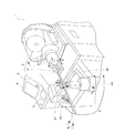
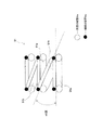
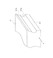
図1は、本実施形態に係る多回曲げ配管製造装置1の外観図である。図1の多回曲げ配管製造装置1は、被接合配管9について曲げ加工や捩り加工等を複数回に渡り繰り返し行うことで、図2に示すようないわゆる多段曲げ構造の被接合配管9(以下、多回曲げ配管91という)を形作る。ここで、被接合配管9とは、互いに径の異なる2つの配管9a,9bが長手方向に接合されたものを言う(図1、図8及び図11参照)。具体的に、本実施形態に係る被接合配管9は、共に銅で形成された配管9a,9bが接合されたものであって、2つの配管9a,9bのうち太径の配管9aは、外径9.5mm、肉厚0.8mmのサイズを有している。一方で、細径の配管9bは、外径4.8mm及び肉厚0.5mmのサイズを有している。配管9a,9bの接合は、例えば自動ハンダ付け機で行われる。そして、多回曲げ配管製造装置1によって製造された多回曲げ配管91は、螺旋状の形状であって、多回曲げ配管91を図2の左側から見ると、図3に示すように、螺旋状かつ上方向に高さを有するような形状となっている。つまり、図2の左側から見た場合、多回曲げ配管91は、水平部分91aと傾斜部分91bとを有しており、これらが繰り返される形状となっている。本実施形態に係る多回曲げ配管91においては、水平部分91a及び傾斜部分91bが約45度の傾斜を有している。
(1) Overview FIG. 1 is an external view of a multi-turn bending pipe manufacturing apparatus 1 according to this embodiment. The multi-bending pipe manufacturing apparatus 1 of FIG. 1 repeats bending processing, twisting processing, and the like for the
尚、上記多回曲げ配管91は、例えば空気調和装置の熱交換器における伝熱管として用いられる。即ち、上記多回曲げ配管91は、伝熱管として複数の伝熱フィンを貫通するように複数設けられる。
In addition, the said multiple
(2)構成
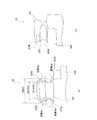
次に、多回曲げ配管製造装置1の構成について説明する。多回曲げ配管製造装置1は、図1及び図4に示すように、主として、曲げ加工部(湾曲部分保持部材に相当)2、捩り部3、表示部4、操作部5及び制御部6を備える。
(2) Configuration Next, the configuration of the multi-turn bending pipe manufacturing apparatus 1 will be described. As shown in FIGS. 1 and 4, the multi-bending pipe manufacturing apparatus 1 mainly includes a bending portion (corresponding to a curved portion holding member) 2, a
〔曲げ加工部〕
曲げ加工部2は、被接合配管9に対し曲げ加工を行うためのものであって、図1に示すように、多回曲げ配管製造装置1に取り付けられた被接合配管9の付近に配置されている。曲げ加工部2は、プレッシャー21、金型22及びクランプ部材23を有する。
(Bending part)
The bending
プレッシャー21は、被接合配管9の長手方向に沿って位置しており、図示しない駆動部によって被接合配管9の長手方向に対し直交する方向(即ち、図1の矢印A)に移動することが可能となっている。これにより、プレッシャー21は、被接合配管9に接触し、被接合配管9を押さえることができる。更に、被接合配管9側を向いているプレッシャー21の面211、即ち被接合配管9と接触する面には、図5に示すように2本の溝211a,211bが形成されている。2本の溝211a、211bは、それぞれ被接合配管9の長手方向に対し平行に延びており、各配管9a,9bの大きさに対応する深さを有している。具体的には、溝211aは、プレッシャー21が被接合配管9に接触した際に太径の配管9aが合致するように形成され、溝211bは、プレッシャー21が被接合配管9に接触した際に細径の配管9bが合致するように形成されている。つまり、各溝211a,211bは、図5において被接合配管9を矢印X方向から見た場合に、半円の形状を有しており、溝211aは溝211bよりも大きい半円となっている。特に、本実施形態では、細径の配管9b用の溝211bが、太径の配管9a用の溝211aよりも上側に位置している。これにより、プレッシャー21は、細径の配管9bが常に太径の配管9aに対し上側に位置するようにして被接合配管9を隙間なく押圧することができる。また、被接合配管9がプレッシャー21の位置する側とは反対側に曲げられる際(図8参照)、プレッシャー21は被接合配管9を押さえていることで、被接合配管9がプレッシャー21側に膨らむのを抑制する役割を担う。
The
金型22は、図1に示すように、被接合配管9を挟んでプレッシャー21の反対側に位置しており、図示しない駆動部によって矢印Bに示すように回動可能に設けられている。金型22は、図6(a)に示すように、上面視において湾曲している部分221を有している。湾曲している部分221の略中央には、金型22と図示しない駆動部とを繋ぐ部材が差し込まれるための孔222が形成されており、この孔222は、金型22の回動中心となる。本実施形態においては、金型22は、上面視において横36mm、縦28mmの大きさを有しており、湾曲している部分221の曲率半径は18mmである。
As shown in FIG. 1, the
また、金型22の側面には、図6(b)及び図7(a)(b)に示すように、水平方向に2本の溝223a,223bが形成されている。各溝223a,223bは、プレッシャー21の面211に形成されている溝211a,211bと同様、金型22が被接合配管9に接触した際に各配管9a,9bが合致するように、半円状に形成されている。太径の配管9a用の溝223aにおける半円形状は、細径の配管9b用の溝223bにおける半円形状よりも大きく、細径の配管9b用の溝223bは、太径の配管9a用の溝223aよりも上側に位置している。尚、本実施形態では、図7(a)に示すように、溝223bの最も深い部分における金型22側部の横方向の長さは25.5mmであって、溝223aの最も深い部分における金型22側部の横方向の長さは20.3mmである。そして、図6(b)に示すように、溝223aと溝223bとの連結部分における金型22側部の横方向の長さは、28.3mmである。更に、金型22における溝223a、223bの下部分は、図6(a)及び図7(a)に示すように、湾曲している部分221とは逆側に突出している突出部224を有している。
Further, as shown in FIGS. 6B and 7A and 7B, two
このような構成を有する金型22によると、溝223a,223bに被接合配管9が合致した状態の金型22が、図1の矢印B方向のうち湾曲している部分221が被接合配管9側となるように90度回動することで、被接合配管9は、湾曲している部分221に沿って180度曲げられる(図8参照)。本実施形態では、説明の便宜上、このようにして曲げられた被接合配管9の部分を“湾曲部分9c”と言う。
According to the
尚、被接合配管9が180度曲げられた後、金型22は、被接合配管9を曲げる時とは逆方向に90度回動し、被接合配管9を曲げる前の状態に戻される。しかしながら、この時、金型22の湾曲していない部分が被接合配管9に接触し、被接合配管9に傷が付いてしまう恐れがある。そこで、本実施形態では、図7(b)に示すように、金型22の湾曲していない部分225を面取りすることで、被接合配管9を曲げる前の状態に金型22を戻す際、被接合配管9に傷がつかないようにしている。
In addition, after the to-
クランプ部材23は、図示しない駆動部によって、図1の矢印C及び矢印Dに示すように移動することができる。具体的には、クランプ部材23は、矢印Cに示すように、プレッシャー21付近と、金型22を挟んでプレッシャー21の反対側との間を移動することができる。また、クランプ部材23は、矢印Dに示すように、斜め上及び斜め下方向に移動することもできる。特に、クランプ部材23は、矢印C及びDに示すように移動する場合においては、被接合配管9との接触面を常に被接合配管9側に向けながら移動する。つまり、クランプ部材23は、矢印Cの方向に移動する場合には、所定の回動軸AX、具体的には金型22を中心として回動するように移動する。また、クランプ部材23における被接合配管9との接触面は、図5のプレッシャー21と同様、被接合配管9の長手方向に延びる2本の溝が形成されている。これにより、クランプ部材23は、被接合配管9を隙間なく押圧することができる。
The
このような構成を有するクランプ部材23は、図8に示すように、被接合配管9を押さえた状態で矢印C1の方向に沿って移動し、プレッシャー21付近の位置から、金型22を挟んでプレッシャー21の反対側に位置するようになる。この時、金型22は矢印B1の方向に90度回動するため、被接合配管9は、金型22の湾曲している部分221に沿って180度曲げられる。また、被接合配管9について上述した曲げ加工及び後述する捩り加工が行われた後、クランプ部材23及び金型22は、曲げ加工が行われる前の位置に戻る。つまり、クランプ部材23は、図1の矢印Dに沿って斜め下方向に移動した後、所定の回動軸AXを中心として図5の矢印C1とは反対の方向に(即ち、プレッシャー21の反対側からプレッシャー21付近へ)回動し、図1の位置に戻る。尚、クランプ部材23が図1の位置に戻る場合、クランプ部材23が被接合配管9と接触してしまうことを避けるため、クランプ部材23は、被接合配管9の下を通過しながら移動する。
As shown in FIG. 8, the
上述したような構成を有する曲げ加工部2は、被接合配管9を曲げる曲げ加工を行うことができる他、被接合配管9の湾曲部分9cを回転不能に保持することができる。以下では、曲げ加工部2が被接合配管9を保持する動作を“閉状態”、保持しない状態を“開状態”と言う。
The bending
〔捩り部〕
捩り部3は、図1に示すように、曲げ加工部2から所定距離離れた箇所に配置されており、曲げ加工部2により曲げられた被接合配管9の湾曲部分9cを固定端として被接合配管9を捩る動作を行う。捩り部3は、主として、チャック部材(第1部分保持部材に相当)31及び回動駆動部32を有する。
[Torsion part]
As shown in FIG. 1, the
チャック部材31は、図8に示すように、被接合配管9の湾曲部分9cから遠い被接合配管9の第1部分9dを保持可能な部材である。本実施形態に係るチャック部材31は、図9に示すように、同じ形状を有する3つの分割部分31a,31b,31cで構成されており、チャック部材31の略中心には、被接合配管9を掴むための孔部311が形成されている。孔部311は、太径の配管9aが合致するための第1孔部311aと、細径の配管9bが合致するための第2孔部311bとで構成される。より具体的には、孔部311は、第1孔部311aと第2孔部311bとが結合された、いわゆるダルマ型の形状となっている。第1孔部311aの直径は、太径の配管9aの外径とほぼ同じ大きさを有しており、第2孔部311bの直径は、細径の配管9bの外径とほぼ同じ大きさを有している。このような構成を有するチャック部材31は、各分割部分31a,31b,31cが一斉に図9の矢印Y1の方向に開いたり、図9の矢印Y2の方向に閉じたりすることで、被接合配管9の第1部分9dを掴むことができる。また、本実施形態に係るチャック部材31は、分割部分31a,31b,31cのうち少なくとも1つが、図9の矢印Y1の方向に開いたり矢印Y2の方向に閉じたりすることもできる。分割部分31a,31b,31cのうち少なくとも1つ(例えば、分割部分31b,31c)が開いたり閉じたりことによって、被被接合配管9の噛み込みを防止することができる。尚、各分割部分31a,31b,31cは、図示しない固定バネと連結されており、各固定バネによって開閉動作を行うことができる。
As shown in FIG. 8, the
また、チャック部材31は、図示しない移動駆動部により、図1の矢印Eの方向に移動することができる。つまり、チャック部材31は、被接合配管9の長手方向に沿って前後に移動することができる。例えば、チャック部材31は、被接合配管9を掴んだ状態で前後方向に移動することができる。これにより、曲げ加工部2によって曲げ加工が施される被接合配管9の位置を調節することが可能となる。
Further, the
ところで、上述したチャック部材31は、耐熱性や耐摩耗性を有し、かつ加工がし易い材質で形成されると良い。具体的には、チャック部材31の材質としては、MCナイロン(登録商標)等が挙げられる。これにより、チャック部材31は、被接合配管9に傷を付けることなく掴むことができる。
Incidentally, the above-described
回動駆動部32は、主としてサーボモータ等で構成されており、その出力軸はチャック部材31に連結されている。回動駆動部32は、チャック部材31を被接合配管9の長手方向を軸として回動させる。即ち、回動駆動部32は、図1の矢印Fに示すように、チャック部材31を回動させることができる。特に、本実施形態に係る回動駆動部32は、被接合配管9の第1部分9dを掴んだ状態のチャック部材31を回動させる。曲げ加工部2が被接合配管9の湾曲部分9cを保持した状態であって、かつ被接合配管9の第1部分9dを掴んだ状態のチャック部材31を回動駆動部32が回動させることで、被接合配管9は、湾曲部分9cを固定端として捩られるようになる。尚、回動駆動部32がチャック部材31を回動させる角度等は、後述する制御部6により制御される。
The
〔表示部及び操作部〕
表示部4は、例えば液晶ディスプレイで構成され、各種画面を表示することができる。例えば、表示部4は、多回曲げ配管製造装置1の各種設定を行うための画面や、多回曲げ配管製造装置1が動作中であることを示す画面、動作中に異常が生じた旨を示す画面等を表示する。
[Display section and operation section]
The
操作部5は、スタートボタン、停止ボタン、及び曲げ加工部2が被接合配管9の保持を解除し開状態となるための保持解除ボタン等の各種ボタンや、テンキー、文字キー等で構成される。スタートボタンは、多回曲げ配管製造装置1が多回曲げ配管91の製造動作を開始するためのボタンである。停止ボタンは、多回曲げ配管91の製造動作を停止させるためのボタンである。テンキーや文字キーは、表示部4に表示された各種設定画面に基づいて多回曲げ配管製造装置1の操作者が各種設定を行う場合等に用いられる。
The operation unit 5 includes various buttons such as a start button, a stop button, a holding release button for the
〔制御部〕
制御部6は、CPU及びメモリからなるマイクロコンピュータで構成されており、図4に示すように各種部材と接続されており、接続された各種部材の動作制御を行う。具体的には、制御部6は、各駆動部を介して曲げ加工部2におけるプレッシャー21、金型22及びクランプ部材23と接続されており、曲げ加工部2が採り得る閉状態及び開状態の状態制御や動作制御を行う。また、制御部6は、表示部4、操作部5、捩り部3の回動駆動部32及びチャック部材31と接続されており、表示部4の表示制御や、捩り部3による被接合配管9の捩り動作制御等を行う。
(Control part)
The
特に、本実施形態に係る制御部6は、曲げ加工部2が被接合配管9の曲げ加工を行った後、捩り部3が被接合配管9の捩り動作を行い、この捩り動作が行われた後に更に曲げ加工部2が被接合配管9について曲げ加工を行うように、曲げ加工部2及び捩り部3の動作制御を行う。即ち、制御部6は、曲げ加工、捩り加工、曲げ加工の順に被接合配管9の加工が行われるように、多回曲げ配管91の製造工程順を制御する。
In particular, in the
また、被接合配管9の捩り動作時では、制御部6は、曲げ加工部2が被接合配管9の湾曲部分9cを回転不能に保持しかつチャック部材31が被接合配管9の第1部分9dを掴んだ状態で、回動駆動部32がチャック部材31を所定角度回動させるように、曲げ加工部2、チャック部材31及び回動駆動部32の動作制御を行う。即ち、制御部6は、被接合配管9の湾曲部分9cが曲げ加工部2により固定された状態で湾曲部分9cから離れた第1部分9dを回動させることにより、被接合配管9の捩り動作を行わせる。ここで、チャック部材31を回動させる際の所定角度としては、例えば45度が挙げられる。
Further, at the time of twisting operation of the
更に、制御部6は、被接合配管9の捩り動作が行われる際、細径の配管9bが太径の配管9aに対し同じ側に位置するように、捩り部3の動作制御を行う。具体的に、本実施形態では、制御部6は、太径の配管9aに対し細径の配管9bが常に上側に位置するように、チャック部材31の回動方向への角度を調節する。つまり、制御部6は、チャック部材31の孔部311における第2孔部311bが第1孔部311aの上となるように、チャック部材31の回動状態を制御する。例えば、被接合配管9の捩り動作時にチャック部材31が45度回動した場合には、制御部6は、回動駆動部32がチャック部材31を捩り動作時とは逆の方向に45度回動させるようにする。
Furthermore, when the twisting operation of the
そして、制御部6は、チャック部材31が所定角度回動した後、曲げ加工部2による被接合配管9の湾曲部分9cの保持を解除させ(即ち、閉状態から開状態にする)、次いでチャック部材31が被接合配管9の第1部分9dを保持した状態で所定角度回動前の状態に戻されるように、曲げ加工部2及び回動駆動部32の動作制御を行う。即ち、制御部6は、所定角度回動したチャック部材31を、回動前の状態に戻す。
Then, after the
(3)多回曲げ配管の製造方法
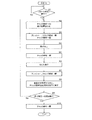
次に、本実施形態に係る多回曲げ配管製造装置1によって多回曲げ配管91が製造される動作について、図10及び図11を用いて説明する。図10は、多回曲げ配管製造装置1によって多回曲げ配管91が製造される過程を順に表したフロー図である。図11は、多回曲げ配管91の製造過程において、被接合配管9が加工される様子を模式的に示した図である。尚、図11では、説明を簡単にするため、被接合配管9、曲げ加工部2、及び捩り部3のチャック部材31のみを抜き出して記載している。
(3) Manufacturing method of multiple bend piping Next, operation | movement in which the multiple bend piping 91 is manufactured by the multiple bend piping manufacturing apparatus 1 which concerns on this embodiment is demonstrated using FIG.10 and FIG.11. FIG. 10 is a flowchart showing in sequence the process in which the
ステップS1:多回曲げ配管製造装置1の操作者により、チャック部材31の孔部311に被接合配管9が通され、被接合配管9が多回曲げ配管製造装置1に取り付けられたとする。この状態で操作部5上のスタートボタンが押下されると(S1のYes)、多回曲げ配管製造装置1は多回曲げ配管91の製造を開始する。尚、以下の動作では、被接合配管9において曲げ加工が行われた回数を制御部6がカウントしていくが、ここでは、制御部6は、このカウント数をリセットさせる。
Step S1: Assume that an operator of the multi-bending pipe manufacturing apparatus 1 passes the bonded
ステップS2:チャック部材31は、孔部311を閉じることで被接合配管9を掴み、被接合配管9を固定する。そして、チャック部材31が図1の矢印Eの方向に移動することで、曲げ加工部2が曲げ加工を行う部分の位置合わせが行われる。
Step S <b> 2: The
ステップS3:曲げ加工部2におけるプレッシャー21及びクランプ部材23は、被接合配管9を保持する閉状態となる。これにより、金型22には、被接合配管9が固定される。その後、チャック部材31の各分割部分31a,31b,31cのうち分割部分31b,31cが図9の矢印Y1の方向に開くことで、チャック部材31は、被接合配管9を放した状態となる(図11の工程A)。より具体的には、この時、分割部分31aは、図示しない固定バネが外された状態であるため、自重にて被接合配管9を押さえているだけとなり、被接合配管9はフリーの状態となっている。
Step S3: The
ステップS4:曲げ加工部2は、被接合配管9について曲げ加工を行う(第1曲げ工程に相当)。即ち、図8に示すように、曲げ加工部2のプレッシャー21は、被接合配管9を固定した状態を保ち、クランプ部材23は、被接合配管9を押圧しながら図8の矢印C1に沿って金型22に対しプレッシャー21の反対側に移動する。この時、金型22は、湾曲している部分221が被接合配管9に接しながら矢印B1の方向へ90度回転する。これにより、図11の工程Bに示すように、被接合配管9は、金型22の湾曲している部分221に沿うようにして180度曲げられた形状となる。尚、制御部6は、被接合配管9において曲げ加工が行われた回数をインクリメントする。
Step S4: The bending
ステップS5:チャック部材31は、各分割部分31a,31b、31cが孔部311を閉じることで被接合配管9の第1部分9dを掴む。
Step S5: The
ステップS6:曲げ加工部2が被接合配管9の湾曲部分9cを回転不能に保持した状態で、捩り部3は、被接合配管9を捩る動作を行う(捩り工程に相当)。即ち、捩り部3におけるチャック部材31は、被接合配管9の第1部分9dを掴んだ状態であることから、回動駆動部32は、曲げ加工部2の保持している被接合配管9の湾曲部分9cを固定端とし、被接合配管9の長手方向を軸としてチャック部材31を45度回動させる(図11の工程C)。
Step S6: In a state where the bending
ステップS7:曲げ加工部2におけるプレッシャー21及びクランプ部材23は、被接合配管9を放した開状態となる。
Step S7: The
ステップS8:金型22がステップS4の時とは逆の方向に90度回転することで回動前の状態に戻ると共に、回動駆動部32は、チャック部材31をステップS6の時とは逆方向に45度回動させ、チャック部材31を回動前の位置に戻す(図11の工程D)。この時、チャック部材31は、被接合配管9の長手方向に前進しながら回動前の状態に戻る。これにより、チャック部材31においては、被接合配管9の細径の配管9bが太径の配管9aに対し上側となるように位置し、被接合配管9の湾曲部分9cは、曲げ加工部2から離れ、約45度上側に持ち上げられた状態となる。尚、クランプ部材23は、被接合配管9の下側を通過し、プレッシャー21付近の位置に戻る。
Step S8: The
ステップS9:制御部6は、被接合配管9において曲げ加工が行われた回数が所定回数に到達したか否かを判断する。到達していない場合には(S9のNo)、ステップS2以降の動作が繰り返される。即ち、チャック部材31が被接合配管9を掴んだ状態で、曲げ加工部2が次に曲げ加工を行う部分の位置合わせが行われる(S3)。そして、プレッシャー21及びクランプ部材23が閉じ、チャック部材31が開いた後、再度曲げ工程が行われる(第2曲げ工程に相当。図11の工程E)。
Step S9: The
ステップS10:ステップS9において、曲げ加工の行われた回数が所定回数に到達したと制御部6が判断した場合(S9のYes)、チャック部材31は、被接合配管9を放した開の状態となり、被接合配管9は、プレッシャー21及びクランプ部材23のみによって閉じられた状態となる。この後、操作者により、操作部5を通じて保持解除ボタンが押下されることで、曲げ加工及び捩り加工が施され多回曲げ配管91となった被接合配管9は、曲げ加工部2から離れる。その後、多回曲げ配管91は、操作者により多回曲げ配管製造装置1から取り出される。
Step S10: In step S9, when the
(4)効果
(A)
本実施形態に係る多回曲げ配管の製造装置1及び製造方法によると、多回曲げ配管91は、2つの配管9a,9bが長手方向に沿うようにして接合された被接合配管9が曲げられた後捩られ、再度曲げられるという工程によって製造される。即ち、本実施形態に係る多回曲げ配管の製造装置1及び製造方法によると、2つの配管9a,9bを接合した状態で多回曲げ配管91を製造することができる。従って、接合されていない配管それぞれを複数箇所で曲げる曲げ加工を行った後に、これらを接合する従来の多回曲げ配管の製造方法に比して、多回曲げ配管91の製造効率が向上する。
(4) Effect (A)
According to the manufacturing apparatus 1 and the manufacturing method for a multi-bend pipe according to the present embodiment, the
(B)
また、本実施形態に係る多回曲げ配管の製造装置1及び製造方法によると、捩り工程では、曲げ加工部2により被接合配管9の湾曲部分9cが回転不能に保持された状態で、湾曲部分9cから離れた被接合配管9の第1部分9dが所定角度回動する。そのため、被接合配管9は、確実かつ容易に捩られるようになる。
(B)
Moreover, according to the manufacturing apparatus 1 and the manufacturing method of the multi-turn bending pipe according to the present embodiment, in the twisting process, the bending
(C)
また、本実施形態に係る多回曲げ配管の製造装置1及び製造方法によると、捩り工程時、曲げ加工部2は、被接合配管9の湾曲部分9cを保持した状態となっているが、捩り工程後、被接合配管9の湾曲部分9cの保持を解除する。そして、捩り工程時より被接合配管9の第1部分9dを固定したままのチャック部材31は、捩り工程後、被接合配管9の捩り工程時における回動方向とは逆の方向に回動し、所定角度回動前の状態に戻される。これにより、捩り工程後、被接合配管9における湾曲部分9cは、曲げ加工部2から離れるため、捩り工程の次に行われる曲げ工程を問題なく行うことができる。
(C)
Moreover, according to the manufacturing apparatus 1 and the manufacturing method of the multi-turn bending pipe according to the present embodiment, the bending
(D)
また、本実施形態に係る多回曲げ配管の製造装置1及び製造方法によると、細径の配管9bが太径の配管9aに対し同じ側に位置するように、被接合配管9が捩られる。そのため、捩り工程後、被接合配管9に対し曲げ工程を行う際には、細径の配管9bの位置を基準として被接合配管9の位置を確認しながら被接合配管9の曲げ工程を行うことができる。
(D)
Moreover, according to the manufacturing apparatus 1 and the manufacturing method of the multi-bending pipe according to the present embodiment, the
<その他の実施形態>
(a)
上記実施形態では、2つの配管9a,9bが長手方向に接合された被接合配管9が、多回曲げ配管91に加工される場合について説明した。しかし、本発明に係る多回曲げ配管の製造装置1及び製造方法は、接合された配管が2つである場合に限定されず、2以上の配管が接合された被接合配管を加工する場合にも適用することができる。
<Other embodiments>
(A)
In the said embodiment, the case where the to-
(b)
上記実施形態では、チャック部材31の長さ(具体的には、被接合配管9の長手方向への長さ)については、特に言及していないが、チャック部材31の長さは、被接合配管9が捩られる際の捩り応力の分散や、被接合配管9の第1部分9dに傷がつくことを防止すること等を考慮し、適宜決定されてもよい。例えば、捩り応力の分散等を考慮しない場合におけるチャック部材31の長さが30mmであれば、捩り応力の分散等を考慮した場合におけるチャック部材31の長さは80mmと決定することができる。
(B)
In the above embodiment, the length of the chuck member 31 (specifically, the length in the longitudinal direction of the
(c)
上記実施形態では、捩り工程において、チャック部材31が45度回動場合について説明したが、チャック部材31の回動角度は、45度に限定されない。チャック部材31の回動角度は、例えば30度や50度であってもよい。
(C)
In the above embodiment, the case where the
(d)
上記実施形態では、第1部分保持部材がチャック部材31である場合を例に取り説明した。しかし、被接合配管9の第1部分9dを保持可能な部材であれば、どのような機構であってもよく、被接合配管9を掴む機構(即ち、チャック部材)に限定されない。
(D)
In the above embodiment, the case where the first partial holding member is the
(e)
上記実施形態では、図10に示すように、被接合配管9において曲げ加工が行われた回数を制御部6がカウントし、この回数が所定回数に満たされた時に多回曲げ配管91の製造動作が終了する場合について説明した。しかし、多回曲げ配管91の製造動作の終了するタイミングは、曲げ加工が行われた回数によって決定される場合に限定されない。例えば、曲げ加工が行われた回数が所定回数に達せずとも、多回曲げ配管製造装置1は、未だ曲げ加工を行われていない配管91の長さが所定長さ以下になった場合に多回曲げ配管91の製造動作を終了してもよい。
(E)
In the above embodiment, as shown in FIG. 10, the
本発明に係る多回曲げ配管の製造方法及び製造装置によると、多回曲げ配管の製造効率が向上するという効果を有しており、熱交換器における伝熱管の製造時に適用することができる。 According to the manufacturing method and the manufacturing apparatus of the multi-bending pipe according to the present invention, it has an effect that the manufacturing efficiency of the multi-bending pipe is improved, and can be applied when manufacturing the heat transfer tube in the heat exchanger.
1 多回曲げ配管製造装置
2 曲げ加工部
3 捩り部
4 表示部
5 操作部
6 制御部
9 被接合配管
9a 太径の配管
9b 細径の配管
9c 湾曲部分
9d 第1部分
21 プレッシャー
22 金型
23 クランプ部材
31 チャック部材
32 回動駆動部
91 多回曲げ配管
311 孔部
311a 第1孔部
311b 第2孔部
DESCRIPTION OF SYMBOLS 1 Multi-bending
Claims (8)
前記第1曲げ工程において曲げられた前記被接合配管(9)の湾曲部分を固定端として前記被接合配管(9)を捩る捩り工程と、
前記捩り工程において捩られた前記被接合配管(9)を曲げる第2曲げ工程と、
を備える、多回曲げ配管の製造方法。 A first bending step of bending the joined pipe (9) joined so that at least two pipes are along the longitudinal direction;
Twisting the to-be-joined pipe (9) with the curved portion of the to-be-joined pipe (9) bent in the first bending step as a fixed end;
A second bending step of bending the joined pipe (9) twisted in the twisting step;
The manufacturing method of multi-bending piping provided with.
請求項1に記載の多回曲げ配管の製造方法。 In the twisting step, in the state where the curved portion of the pipe to be joined (9) is held in a non-rotatable state by the curved portion holding member (2), the longitudinal direction of the pipe to be joined (9) is used as an axis. Rotating a first portion of the pipe (9) away from the curved portion by a predetermined angle;
The method for producing a multi-turn bent pipe according to claim 1.
前記捩り工程後、前記湾曲部分保持部材(2)が前記湾曲部分の保持を解除すると共に、前記第1部分を保持した状態の前記第1部分保持部材(31)を前記所定角度回動前の状態に戻す、
請求項2に記載の多回曲げ配管の製造方法。 In the twisting step, the first part holding member (31) holding the first part is rotated by the predetermined angle,
After the twisting step, the curved portion holding member (2) releases the holding of the curved portion, and the first portion holding member (31) in a state of holding the first portion is rotated before the predetermined angle. Return to the state,
The manufacturing method of the multiple times bending piping of Claim 2.
前記捩り工程では、2つの前記配管(9a,9b)のうち細径の前記配管(9b)が太径の前記配管(9a)に対し同じ側に位置するように、前記被接合配管(9)が捩られる、
請求項1〜3のいずれかに記載の多回曲げ配管の製造方法。 The joined pipe (9) has two pipes (9a, 9b) having different diameters from each other,
In the twisting process, the pipe to be joined (9) is arranged such that the small diameter pipe (9b) of the two pipes (9a, 9b) is located on the same side with respect to the large diameter pipe (9a). Is twisted,
The manufacturing method of the multiple bend piping in any one of Claims 1-3.
前記曲げ加工部(2)により曲げられた前記被接合配管(9)の湾曲部分を固定端として前記被接合部材(9)を捩る捩り部(3)と、
前記曲げ加工部(2)が前記被接合配管(9)の曲げ加工を行った後前記捩り部(3)が前記被接合配管(9)の捩り動作を行い、前記捩り部(3)による捩り動作後に前記曲げ加工部(2)が前記被接合配管(9)の曲げ加工を行うように、前記曲げ加工部(2)及び前記捩り部(3)の動作制御を行う制御部(6)と、
を備える、多回曲げ配管の製造装置(1)。 A bending portion (2) that performs bending on the pipe (9) to be joined, in which at least two pipes are joined along the longitudinal direction;
A twisted part (3) for twisting the joined member (9) with the curved portion of the joined pipe (9) bent by the bending part (2) as a fixed end;
After the bending portion (2) bends the pipe (9) to be joined, the twist portion (3) twists the pipe (9) and twists by the twist portion (3). A controller (6) for controlling the operation of the bending section (2) and the twisting section (3) so that the bending section (2) bends the pipe (9) after operation; ,
A multi-bending pipe manufacturing apparatus (1).
前記捩り部(3)は、前記湾曲部分から遠い前記被接合配管(9)の第1部分を保持可能な第1部分保持部材(31)と、前記第1部分保持部材(31)を前記被接合配管(9)の長手方向を軸として回動させることが可能な回動駆動部(32)とを有し、
前記制御部(6)は、前記捩り動作時、前記曲げ加工部(2)が前記被接合配管(9)の前記湾曲部分を回転不能に保持しかつ前記第1部分保持部材(31)が前記被接合配管(9)の前記第1部分を保持した状態で前記回動駆動部(32)が前記第1部分保持部材(31)を所定角度回動させるように、前記曲げ加工部(2)、前記第1部分保持部材(31)及び前記回動駆動部(32)の動作制御を行う、
請求項5に記載の多回曲げ配管の製造装置(1)。 The bending portion (2) can hold the curved portion of the joined pipe (9) in a non-rotatable manner,
The torsion part (3) includes a first part holding member (31) capable of holding a first part of the joined pipe (9) far from the curved part, and the first part holding member (31). A rotation drive unit (32) capable of rotating about the longitudinal direction of the joining pipe (9),
In the control section (6), during the twisting operation, the bending section (2) holds the curved portion of the pipe (9) to be non-rotatable and the first portion holding member (31) The bending portion (2) so that the rotation driving portion (32) rotates the first portion holding member (31) by a predetermined angle while holding the first portion of the pipe (9) to be joined. The operation control of the first part holding member (31) and the rotation drive unit (32) is performed.
The multi-bending pipe manufacturing apparatus (1) according to claim 5.
請求項6に記載の多回曲げ配管の製造装置(1)。 The control unit (6) includes the first part holding member (31) while the bending part (2) releases the holding of the curved part after the first part holding member (31) rotates by a predetermined angle. Control the operation of the bending portion (2) and the rotation drive portion (32) so that the first portion is held and returned to the state before the predetermined angle rotation.
The multi-bending pipe manufacturing apparatus (1) according to claim 6.
前記制御部(6)は、前記捩り動作時、2つの前記配管(9a,9b)のうち細径の前記配管(9b)が太径の前記配管(9a)に対し同じ側に位置するように、前記捩り部(3)の動作制御を行う、
請求項5〜7のいずれかに記載の多回曲げ配管の製造装置(1)。 The joined pipe (9) has two pipes (9a, 9b) having different diameters from each other,
The controller (6) is configured such that, during the twisting operation, the small diameter pipe (9b) of the two pipes (9a, 9b) is located on the same side with respect to the large diameter pipe (9a). , Controlling the operation of the torsion part (3).
The manufacturing apparatus (1) for multi-turn bending pipe according to any one of claims 5 to 7.
Priority Applications (1)
| Application Number | Priority Date | Filing Date | Title |
|---|---|---|---|
| JP2008183801A JP5210740B2 (en) | 2008-07-15 | 2008-07-15 | Multi-bending pipe manufacturing method and multi-bending pipe manufacturing apparatus |
Applications Claiming Priority (1)
| Application Number | Priority Date | Filing Date | Title |
|---|---|---|---|
| JP2008183801A JP5210740B2 (en) | 2008-07-15 | 2008-07-15 | Multi-bending pipe manufacturing method and multi-bending pipe manufacturing apparatus |
Publications (2)
| Publication Number | Publication Date |
|---|---|
| JP2010023046A true JP2010023046A (en) | 2010-02-04 |
| JP5210740B2 JP5210740B2 (en) | 2013-06-12 |
Family
ID=41729378
Family Applications (1)
| Application Number | Title | Priority Date | Filing Date |
|---|---|---|---|
| JP2008183801A Expired - Fee Related JP5210740B2 (en) | 2008-07-15 | 2008-07-15 | Multi-bending pipe manufacturing method and multi-bending pipe manufacturing apparatus |
Country Status (1)
| Country | Link |
|---|---|
| JP (1) | JP5210740B2 (en) |
Cited By (6)
| Publication number | Priority date | Publication date | Assignee | Title |
|---|---|---|---|---|
| JP2013011404A (en) * | 2011-06-29 | 2013-01-17 | Noritz Corp | Heat exchanger and method of manufacturing the same |
| CN103394564A (en) * | 2013-08-02 | 2013-11-20 | 安徽省宁国市天成电机有限公司 | Mechanical type pipe bending device |
| JP2015085375A (en) * | 2013-11-01 | 2015-05-07 | 株式会社クネット・インターナショナル | Wavy handrail formation device |
| CN109454133A (en) * | 2017-09-06 | 2019-03-12 | 丹佛斯微通道换热器(嘉兴)有限公司 | For the method for heat exchanger bending, heat exchanger tube space mechanism and system |
| DE102018215501A1 (en) * | 2018-09-12 | 2020-03-12 | Wafios Aktiengesellschaft | Process for producing a bent part and bending machine for carrying out the process |
| KR102167972B1 (en) * | 2019-09-30 | 2020-10-20 | 김성철 | Apparatus for bending multiple pipes |
Citations (5)
| Publication number | Priority date | Publication date | Assignee | Title |
|---|---|---|---|---|
| JPH10146619A (en) * | 1996-11-18 | 1998-06-02 | Usui Internatl Ind Co Ltd | Device for bending tube |
| JP2007218551A (en) * | 2006-02-20 | 2007-08-30 | Matsushita Electric Ind Co Ltd | Heat exchanger and heat pump water heater using it |
| JP2007326141A (en) * | 2006-06-09 | 2007-12-20 | Mitsubishi Electric Corp | Method of manufacturing spiral multistage type heat exchanger and spiral multistage type heat exchanger |
| JP2008025902A (en) * | 2006-07-20 | 2008-02-07 | Fuji Electric Retail Systems Co Ltd | Heat exchanger and method of manufacturing heat exchanger |
| JP2008116112A (en) * | 2006-11-02 | 2008-05-22 | Denso Corp | Heat exchanger |
-
2008
- 2008-07-15 JP JP2008183801A patent/JP5210740B2/en not_active Expired - Fee Related
Patent Citations (5)
| Publication number | Priority date | Publication date | Assignee | Title |
|---|---|---|---|---|
| JPH10146619A (en) * | 1996-11-18 | 1998-06-02 | Usui Internatl Ind Co Ltd | Device for bending tube |
| JP2007218551A (en) * | 2006-02-20 | 2007-08-30 | Matsushita Electric Ind Co Ltd | Heat exchanger and heat pump water heater using it |
| JP2007326141A (en) * | 2006-06-09 | 2007-12-20 | Mitsubishi Electric Corp | Method of manufacturing spiral multistage type heat exchanger and spiral multistage type heat exchanger |
| JP2008025902A (en) * | 2006-07-20 | 2008-02-07 | Fuji Electric Retail Systems Co Ltd | Heat exchanger and method of manufacturing heat exchanger |
| JP2008116112A (en) * | 2006-11-02 | 2008-05-22 | Denso Corp | Heat exchanger |
Cited By (6)
| Publication number | Priority date | Publication date | Assignee | Title |
|---|---|---|---|---|
| JP2013011404A (en) * | 2011-06-29 | 2013-01-17 | Noritz Corp | Heat exchanger and method of manufacturing the same |
| CN103394564A (en) * | 2013-08-02 | 2013-11-20 | 安徽省宁国市天成电机有限公司 | Mechanical type pipe bending device |
| JP2015085375A (en) * | 2013-11-01 | 2015-05-07 | 株式会社クネット・インターナショナル | Wavy handrail formation device |
| CN109454133A (en) * | 2017-09-06 | 2019-03-12 | 丹佛斯微通道换热器(嘉兴)有限公司 | For the method for heat exchanger bending, heat exchanger tube space mechanism and system |
| DE102018215501A1 (en) * | 2018-09-12 | 2020-03-12 | Wafios Aktiengesellschaft | Process for producing a bent part and bending machine for carrying out the process |
| KR102167972B1 (en) * | 2019-09-30 | 2020-10-20 | 김성철 | Apparatus for bending multiple pipes |
Also Published As
| Publication number | Publication date |
|---|---|
| JP5210740B2 (en) | 2013-06-12 |
Similar Documents
| Publication | Publication Date | Title |
|---|---|---|
| JP5210740B2 (en) | Multi-bending pipe manufacturing method and multi-bending pipe manufacturing apparatus | |
| JP4591908B2 (en) | Pipe bending machine | |
| WO2016203847A1 (en) | Pipe bending device | |
| JP2008126268A (en) | Method and device for bending hair-pin tube | |
| JP2010029900A (en) | Cylinder forming apparatus | |
| JP4999468B2 (en) | Spiral tube manufacturing method and spiral tube manufacturing apparatus | |
| JP5829670B2 (en) | Bending clamp, processing unit and processing equipment | |
| JP4883625B2 (en) | Multistage lap bending method and apparatus for finned meander tube | |
| JP2016022505A (en) | Manufacturing method and manufacturing apparatus of pipe with spiral grooved inner surface | |
| JP2014140896A (en) | Tube with spiral groove on inner surface, manufacturing method therefor, and heat exchanger | |
| US7021107B2 (en) | Bending processor of pipe | |
| JP5383245B2 (en) | Pipe bending machine | |
| JP6584027B2 (en) | Twisted tube with internal spiral groove and heat exchanger | |
| US5502997A (en) | Gripper and mandrel assembly for tube bender | |
| JP6215884B2 (en) | Processing unit and processing equipment | |
| CN109791029B (en) | Method for manufacturing tube with built-in fin and method for manufacturing double-layer tube | |
| CN101817038A (en) | Bending mechanism of double shaft bi-directional pipe bender | |
| JP6502914B2 (en) | Method and apparatus for manufacturing double pipe | |
| JP6502912B2 (en) | Method and apparatus for manufacturing fin-incorporated tube | |
| JP6502913B2 (en) | Fin built-in tube | |
| JP4598371B2 (en) | Hairpin bending copper tube and hairpin bending method for copper tube | |
| JPH1058049A (en) | Multistage piling bending method for meandering tube with fin and device therefor | |
| JP2019130595A (en) | Manufacturing method for double pipe | |
| JP6355039B2 (en) | Internal spiral groove manufacturing equipment | |
| JP3743342B2 (en) | Spiral inner grooved tube and manufacturing method thereof |
Legal Events
| Date | Code | Title | Description |
|---|---|---|---|
| A621 | Written request for application examination |
Free format text: JAPANESE INTERMEDIATE CODE: A621 Effective date: 20110606 |
|
| A977 | Report on retrieval |
Free format text: JAPANESE INTERMEDIATE CODE: A971007 Effective date: 20130122 |
|
| TRDD | Decision of grant or rejection written | ||
| A01 | Written decision to grant a patent or to grant a registration (utility model) |
Free format text: JAPANESE INTERMEDIATE CODE: A01 Effective date: 20130129 |
|
| A61 | First payment of annual fees (during grant procedure) |
Free format text: JAPANESE INTERMEDIATE CODE: A61 Effective date: 20130225 |
|
| FPAY | Renewal fee payment (event date is renewal date of database) |
Free format text: PAYMENT UNTIL: 20160301 Year of fee payment: 3 |
|
| R150 | Certificate of patent or registration of utility model |
Ref document number: 5210740 Country of ref document: JP Free format text: JAPANESE INTERMEDIATE CODE: R150 Free format text: JAPANESE INTERMEDIATE CODE: R150 |
|
| R250 | Receipt of annual fees |
Free format text: JAPANESE INTERMEDIATE CODE: R250 |
|
| R250 | Receipt of annual fees |
Free format text: JAPANESE INTERMEDIATE CODE: R250 |
|
| R250 | Receipt of annual fees |
Free format text: JAPANESE INTERMEDIATE CODE: R250 |
|
| R250 | Receipt of annual fees |
Free format text: JAPANESE INTERMEDIATE CODE: R250 |
|
| R250 | Receipt of annual fees |
Free format text: JAPANESE INTERMEDIATE CODE: R250 |
|
| R250 | Receipt of annual fees |
Free format text: JAPANESE INTERMEDIATE CODE: R250 |
|
| R250 | Receipt of annual fees |
Free format text: JAPANESE INTERMEDIATE CODE: R250 |
|
| LAPS | Cancellation because of no payment of annual fees |