JP2010023006A - Pure water production method - Google Patents
Pure water production method Download PDFInfo
- Publication number
- JP2010023006A JP2010023006A JP2008191171A JP2008191171A JP2010023006A JP 2010023006 A JP2010023006 A JP 2010023006A JP 2008191171 A JP2008191171 A JP 2008191171A JP 2008191171 A JP2008191171 A JP 2008191171A JP 2010023006 A JP2010023006 A JP 2010023006A
- Authority
- JP
- Japan
- Prior art keywords
- reverse osmosis
- water
- osmosis device
- recovery rate
- pure water
- Prior art date
- Legal status (The legal status is an assumption and is not a legal conclusion. Google has not performed a legal analysis and makes no representation as to the accuracy of the status listed.)
- Granted
Links
- XLYOFNOQVPJJNP-UHFFFAOYSA-N water Substances O XLYOFNOQVPJJNP-UHFFFAOYSA-N 0.000 title claims abstract description 235
- 238000004519 manufacturing process Methods 0.000 title claims abstract description 31
- 238000001223 reverse osmosis Methods 0.000 claims abstract description 193
- 238000011084 recovery Methods 0.000 claims abstract description 78
- NWUYHJFMYQTDRP-UHFFFAOYSA-N 1,2-bis(ethenyl)benzene;1-ethenyl-2-ethylbenzene;styrene Chemical compound C=CC1=CC=CC=C1.CCC1=CC=CC=C1C=C.C=CC1=CC=CC=C1C=C NWUYHJFMYQTDRP-UHFFFAOYSA-N 0.000 claims abstract description 17
- 239000003729 cation exchange resin Substances 0.000 claims abstract description 14
- 238000007872 degassing Methods 0.000 claims description 6
- 239000002253 acid Substances 0.000 claims description 5
- 239000012466 permeate Substances 0.000 claims description 4
- 230000008929 regeneration Effects 0.000 claims description 2
- 238000011069 regeneration method Methods 0.000 claims description 2
- 229910021642 ultra pure water Inorganic materials 0.000 abstract description 3
- 239000012498 ultrapure water Substances 0.000 abstract description 3
- VYPSYNLAJGMNEJ-UHFFFAOYSA-N Silicium dioxide Chemical compound O=[Si]=O VYPSYNLAJGMNEJ-UHFFFAOYSA-N 0.000 description 40
- 230000000052 comparative effect Effects 0.000 description 31
- 239000012528 membrane Substances 0.000 description 29
- 239000000377 silicon dioxide Substances 0.000 description 20
- 238000000034 method Methods 0.000 description 18
- ZOXJGFHDIHLPTG-UHFFFAOYSA-N Boron Chemical compound [B] ZOXJGFHDIHLPTG-UHFFFAOYSA-N 0.000 description 17
- 229910052796 boron Inorganic materials 0.000 description 17
- HEMHJVSKTPXQMS-UHFFFAOYSA-M Sodium hydroxide Chemical compound [OH-].[Na+] HEMHJVSKTPXQMS-UHFFFAOYSA-M 0.000 description 9
- 239000000047 product Substances 0.000 description 7
- 239000003899 bactericide agent Substances 0.000 description 4
- 239000000126 substance Substances 0.000 description 4
- KWYUFKZDYYNOTN-UHFFFAOYSA-M Potassium hydroxide Chemical compound [OH-].[K+] KWYUFKZDYYNOTN-UHFFFAOYSA-M 0.000 description 3
- 229920002125 Sokalan® Polymers 0.000 description 3
- 239000003513 alkali Substances 0.000 description 3
- 239000003456 ion exchange resin Substances 0.000 description 3
- 229920003303 ion-exchange polymer Polymers 0.000 description 3
- 239000007788 liquid Substances 0.000 description 3
- 239000002455 scale inhibitor Substances 0.000 description 3
- 235000011121 sodium hydroxide Nutrition 0.000 description 3
- VTYYLEPIZMXCLO-UHFFFAOYSA-L Calcium carbonate Chemical compound [Ca+2].[O-]C([O-])=O VTYYLEPIZMXCLO-UHFFFAOYSA-L 0.000 description 2
- OKTJSMMVPCPJKN-UHFFFAOYSA-N Carbon Chemical compound [C] OKTJSMMVPCPJKN-UHFFFAOYSA-N 0.000 description 2
- VEXZGXHMUGYJMC-UHFFFAOYSA-N Hydrochloric acid Chemical compound Cl VEXZGXHMUGYJMC-UHFFFAOYSA-N 0.000 description 2
- QAOWNCQODCNURD-UHFFFAOYSA-N Sulfuric acid Chemical compound OS(O)(=O)=O QAOWNCQODCNURD-UHFFFAOYSA-N 0.000 description 2
- 230000000844 anti-bacterial effect Effects 0.000 description 2
- 229920001429 chelating resin Polymers 0.000 description 2
- 230000015271 coagulation Effects 0.000 description 2
- 238000005345 coagulation Methods 0.000 description 2
- 230000000694 effects Effects 0.000 description 2
- 239000000945 filler Substances 0.000 description 2
- 238000001914 filtration Methods 0.000 description 2
- 239000007789 gas Substances 0.000 description 2
- 230000003993 interaction Effects 0.000 description 2
- 150000002500 ions Chemical class 0.000 description 2
- 239000003002 pH adjusting agent Substances 0.000 description 2
- 235000019353 potassium silicate Nutrition 0.000 description 2
- 238000004062 sedimentation Methods 0.000 description 2
- NTHWMYGWWRZVTN-UHFFFAOYSA-N sodium silicate Chemical compound [Na+].[Na+].[O-][Si]([O-])=O NTHWMYGWWRZVTN-UHFFFAOYSA-N 0.000 description 2
- 239000008400 supply water Substances 0.000 description 2
- 239000002351 wastewater Substances 0.000 description 2
- 239000002349 well water Substances 0.000 description 2
- 235000020681 well water Nutrition 0.000 description 2
- GUUULVAMQJLDSY-UHFFFAOYSA-N 4,5-dihydro-1,2-thiazole Chemical compound C1CC=NS1 GUUULVAMQJLDSY-UHFFFAOYSA-N 0.000 description 1
- 229910004298 SiO 2 Inorganic materials 0.000 description 1
- 238000005273 aeration Methods 0.000 description 1
- -1 boron as well as gas Chemical class 0.000 description 1
- 229910000019 calcium carbonate Inorganic materials 0.000 description 1
- BVKZGUZCCUSVTD-UHFFFAOYSA-N carbonic acid Chemical compound OC(O)=O BVKZGUZCCUSVTD-UHFFFAOYSA-N 0.000 description 1
- 238000005341 cation exchange Methods 0.000 description 1
- 238000006243 chemical reaction Methods 0.000 description 1
- 238000006114 decarboxylation reaction Methods 0.000 description 1
- 230000007423 decrease Effects 0.000 description 1
- 230000002542 deteriorative effect Effects 0.000 description 1
- 238000010586 diagram Methods 0.000 description 1
- 239000000835 fiber Substances 0.000 description 1
- 239000010419 fine particle Substances 0.000 description 1
- 238000002347 injection Methods 0.000 description 1
- 239000007924 injection Substances 0.000 description 1
- 238000005342 ion exchange Methods 0.000 description 1
- 239000004973 liquid crystal related substance Substances 0.000 description 1
- 230000007257 malfunction Effects 0.000 description 1
- 238000002156 mixing Methods 0.000 description 1
- 238000010979 pH adjustment Methods 0.000 description 1
- 238000001556 precipitation Methods 0.000 description 1
- 239000011347 resin Substances 0.000 description 1
- 229920005989 resin Polymers 0.000 description 1
- 239000004065 semiconductor Substances 0.000 description 1
- 229910001415 sodium ion Inorganic materials 0.000 description 1
- 238000001179 sorption measurement Methods 0.000 description 1
- 238000000108 ultra-filtration Methods 0.000 description 1
- 238000009849 vacuum degassing Methods 0.000 description 1
- 238000005406 washing Methods 0.000 description 1
- 238000004065 wastewater treatment Methods 0.000 description 1
Images


Landscapes
- Separation Using Semi-Permeable Membranes (AREA)
- Treatment Of Water By Ion Exchange (AREA)
- Physical Water Treatments (AREA)
Abstract
Description
本発明は、逆浸透装置を用いた純水製造方法に係り、特に、少なくとも2つの逆浸透装置を用い、最初の逆浸透装置の濃縮水を他の逆浸透装置で処理して、その透過水を被処理水として再利用する純水製造方法に関する。 The present invention relates to a method for producing pure water using a reverse osmosis device, and in particular, using at least two reverse osmosis devices, treating the concentrated water of the first reverse osmosis device with another reverse osmosis device, and the permeated water. The present invention relates to a method for producing pure water that is reused as treated water.
半導体や液晶の製造において使われる超純水は、従来から、市水、井水又は洗浄廃水などから製造され、そのシステムは、前処理工程、一次純水製造工程、二次純水製造工程(サブシステムとも呼ばれる)と3つの工程で構成されている。 Ultrapure water used in the production of semiconductors and liquid crystals has been conventionally produced from city water, well water, or washing wastewater, and the system consists of pretreatment process, primary pure water production process, secondary pure water production process ( It is also composed of three processes.
前処理工程では、凝集沈殿処理、ろ過処理など、一次純水製造工程では、ろ過処理、逆浸透膜処理、限外濾過処理、イオン交換処理などを組み合わせた処理が行われている。 In the pretreatment process, a combination of filtration, reverse osmosis membrane treatment, ultrafiltration treatment, ion exchange treatment, and the like is performed in the primary pure water production process such as coagulation sedimentation treatment and filtration treatment.
そのなかで、逆浸透膜処理は、イオン性物質、微粒子、有機物、一部の溶存気体等ほぼ全てに関して、除去する効果があることや、詰まりやトラブルが発生しない限り、再生等の不連続の工程を実施しなくても良い等の点から広く使われている。しかし、被処理水の一部を濃縮水として排出するため、水の利用率が下がること、ガスはもちろん、ホウ素等の一部のイオンの除去率が低いこと、シリカや硬度等による詰まりが発生しやすいという欠点も存在する。 Among them, reverse osmosis membrane treatment has the effect of removing almost all ionic substances, fine particles, organic substances, some dissolved gases, etc., and is free of discontinuities such as regeneration unless clogging or trouble occurs. Widely used from the point of not having to carry out the process. However, since part of the water to be treated is discharged as concentrated water, the water utilization rate decreases, the removal rate of some ions such as boron as well as gas, clogging due to silica, hardness, etc. occurs. There is also the disadvantage of being easy to do.
これらの欠点を克服する方法として、逆浸透膜処理を強アルカリ条件で行う方法が開示されている(例えば、特許文献1参照。)。この方法は、逆浸透膜の詰まりの原因の1つであるシリカの水中での挙動を考慮し、シリカの少なくとも大部分がイオン状で存在するpH(pH≧10)において運転することによって、シリカによる逆浸透膜の詰まりを抑制したものである。そのため、シリカの詰まりを考慮する必要がなくなり、水回収率を90%以上に上げることが可能となった。また、このようなpH条件においては、ホウ素もイオンとして存在するため、ホウ素に関しても十分な除去率を得ることができる。 As a method of overcoming these drawbacks, a method of performing reverse osmosis membrane treatment under strong alkaline conditions has been disclosed (for example, see Patent Document 1). This method considers the behavior of silica in water, which is one of the causes of clogging of reverse osmosis membranes, and operates at a pH (pH ≧ 10) where at least most of the silica is present in an ionic state. This prevents clogging of the reverse osmosis membrane. Therefore, it is not necessary to consider silica clogging, and the water recovery rate can be increased to 90% or more. Further, under such pH conditions, since boron is also present as ions, a sufficient removal rate can be obtained for boron.
しかし、水回収率をさらに上げていくと、システムとしての除去率は悪化する。これは、水回収率を上げるということは、濃縮された水を逆浸透処理することになることから、必然的に透過水の水質が悪化するためであり、上記システムでの水回収率は、90%〜95%程度が限界とされている。 However, if the water recovery rate is further increased, the removal rate as a system deteriorates. This is because increasing the water recovery rate means reverse osmosis treatment of the concentrated water, which inevitably deteriorates the quality of the permeate, and the water recovery rate in the above system is The limit is about 90% to 95%.
そこで、アルカリ条件で運転した逆浸透膜の濃縮水を、さらに別の逆浸透膜で処理した後、前段に戻す技術も、すでに開示されている(例えば、特許文献2及び3参照。)。これらの方法により、純水製造装置の後段の水質が悪化することなく、回収率を向上させることが可能となった。
このような逆浸透処理において、硬度スケールに対する対策のため、事前の処理が必須であり、例えば、特許文献2においては図に示されているカチオン交換樹脂装置1及び脱気装置2がそれに該当する。しかし、これらの装置を設けても完全に硬度成分を除去することは不可能である。
In such reverse osmosis treatment, prior treatment is indispensable for measures against the hardness scale. For example, in
また、スケールは、高濃縮された条件においてより激しく発生するため、特許文献2や3の純水製造装置では、第2の逆浸透装置において、硬度スケールが懸念される。したがって、第2の逆浸透装置の運転条件は、硬度スケール発生の可能性を考慮したうえで設定しなければならない。
In addition, since the scale is generated more vigorously under highly concentrated conditions, there is a concern about the hardness scale in the second reverse osmosis apparatus in the pure water production apparatuses of
通常、逆浸透装置の膜の詰まりの有無を判断する手段にランゲラーインデックスが有る。これは、硬度による逆浸透膜の詰まりを予測する尺度であり、逆浸透装置の設計では一般的に使われている方法である。しかし、これは、被処理水の液性が中性付近における硬度による膜の詰まりの有無を判断する方法であり、このように高アルカリ条件における詰まりを判断することはできない。 Usually, there is a Langeller index as a means for determining whether or not a membrane of a reverse osmosis device is clogged. This is a measure for predicting clogging of a reverse osmosis membrane due to hardness, and is a method commonly used in the design of reverse osmosis devices. However, this is a method for judging whether or not the liquid of the water to be treated is clogged due to the hardness near neutrality, and thus clogging under high alkali conditions cannot be judged.
そこで、炭酸カルシウムの溶解度積から、詰まりの有無を推定する方法を適用すると、仮に、第1の逆浸透装置の入口炭酸濃度が10mg/L as CO2、第1の逆浸透装置の入口硬度が5μg/L as CaCO3、CaCO3の溶解度積は2.90×10⁻⁹、第1の逆浸透装置の水回収率90%とした場合、第2の逆浸透装置の水回収率は、37%が最大と算出できる。 Therefore, if a method for estimating the presence or absence of clogging from the solubility product of calcium carbonate is applied, the inlet carbonic acid concentration of the first reverse osmosis device is 10 mg / L as CO 2 , and the inlet hardness of the first reverse osmosis device is When the solubility product of 5 μg / L as CaCO 3 and CaCO 3 is 2.90 × 10 −9 and the water recovery rate of the first reverse osmosis device is 90%, the water recovery rate of the second reverse osmosis device is 37 % Can be calculated as the maximum.
ただし、この方法では、第1の逆浸透装置の入口の水質を正確に把握することが必要であるが、これは、前処理装置の運転状況によって変動しやすい。また、第2の逆浸透装置内の複雑な反応を、単純化して、溶解度積のみから推定することは正確性に欠け、大幅なずれが生じるおそれもある。したがって、この方法のみから、最適な運転条件を正確に決定することは困難である。 However, in this method, it is necessary to accurately grasp the water quality at the inlet of the first reverse osmosis device, but this is likely to vary depending on the operating conditions of the pretreatment device. In addition, simplifying the complex reaction in the second reverse osmosis device and estimating it from the solubility product alone is not accurate and may cause a significant shift. Therefore, it is difficult to accurately determine the optimum operating conditions only from this method.
また、一般的に、逆浸透装置の膜の詰まりの速度は、濃縮倍率すなわち、被処理水流量/濃縮水流量の値にほぼ比例すると言われている。したがって、第2の逆浸透装置の場合、第1の逆浸透装置よりも膜の詰まりが激しくなる。たとえば、第1の逆浸透装置の膜寿命は1年〜2年程度が最低限必要だが、仮に第1の逆浸透装置の寿命が1年〜2年と仮定すると、第2の逆浸透装置の寿命は、上記の関係から、次のように試算される。 In general, it is said that the rate of clogging of the membrane of the reverse osmosis apparatus is substantially proportional to the concentration ratio, that is, the value of the flow rate of treated water / the flow rate of concentrated water. Therefore, in the case of the second reverse osmosis device, the membrane becomes clogged more severely than the first reverse osmosis device. For example, the minimum membrane life of the first reverse osmosis device is required to be about 1 to 2 years, but if the lifetime of the first reverse osmosis device is assumed to be 1 to 2 years, The lifetime is estimated from the above relationship as follows.

なお、濃縮倍率と水回収率の関係は、次のとおりである。なお、この式において水回収率は、百分率ではなく回収割合(0〜1の範囲)で表した数値により算出する。
濃縮倍率=1/(1−水回収率)
すなわち、濃縮倍率ないし、水回収率を上げると、第2の逆浸透装置の膜寿命は急激に短くなるので、頻繁に膜を交換するか、洗浄する必要が生じ、安定した運転が不可能となってしまう。
The relationship between the concentration rate and the water recovery rate is as follows. In this formula, the water recovery rate is calculated not by percentage but by a numerical value expressed by a recovery rate (range of 0 to 1).
Concentration magnification = 1 / (1-water recovery rate)
In other words, if the concentration factor or the water recovery rate is increased, the membrane life of the second reverse osmosis device will be shortened rapidly, so it will be necessary to frequently replace or wash the membrane, making stable operation impossible. turn into.
上記2つの知見から、第2の逆浸透装置は、水回収率が50〜66%程度で運転されるのが通常であり、75〜80%程度が技術的限界と考えられていた。 From the above two findings, the second reverse osmosis device is usually operated at a water recovery rate of about 50 to 66%, and about 75 to 80% was considered a technical limit.
ところが、上記のように、溶解度、及び濃縮倍率から推定される膜の寿命を考慮して装置を設計しているにもかかわらず、第2の逆浸透装置の膜の詰まりが起きる問題が発生していた。 However, as described above, there is a problem that the membrane of the second reverse osmosis device is clogged although the device is designed in consideration of the solubility and the lifetime of the membrane estimated from the concentration factor. It was.
そこで、本発明の目的は、上記のような逆浸透装置を2つ用いる純水製造装置において、逆浸透装置の水回収率の向上を図るとともに、硬度スケールによる詰まりを抑制して純水製造装置の運転を安定に維持することが可能な純水製造方法を提供することである。 Accordingly, an object of the present invention is to provide a pure water production apparatus that uses two reverse osmosis devices as described above, while improving the water recovery rate of the reverse osmosis device and suppressing clogging due to the hardness scale. It is to provide a pure water production method capable of stably maintaining the operation.
本発明の純水製造方法は、原水をH型のカチオン交換樹脂塔に通水した後、脱ガス装置にて脱ガス処理し、次いでpH10以上のアルカリ性条件として第1の逆浸透装置に通水して純水を製造するに当たり、第1の逆浸透装置から排出されるアルカリ性の濃縮水を、別途設けられた第2の逆浸透装置に通水して、その透過水を第1の逆浸透装置の前段に返送する純水製造方法であって、第1の逆浸透装置における水回収率を90〜95%とし、第2の逆浸透装置における水回収率を97%以下で、かつ、次式(1)
Y≧100−50.5/(100−X) …(1)
(ただし、Yは第2の逆浸透装置の水回収率(%)、Xは第1の逆浸透装置の水回収率(%)を表す。)の関係を満たす範囲とすることを特徴とするものである。
In the pure water production method of the present invention, raw water is passed through an H-type cation exchange resin tower, then degassed with a degasser, and then passed through the first reverse osmosis device under alkaline conditions of
Y ≧ 100-50.5 / (100-X) (1)
(Where Y represents the water recovery rate (%) of the second reverse osmosis device, and X represents the water recovery rate (%) of the first reverse osmosis device). Is.
本発明の純水製造方法は、pH≧10にて運転される第1の逆浸透装置の濃縮水をさらに第2の逆浸透装置にて処理し、その透過水を、前段に返送する装置において、第2の逆浸透装置における詰まりが、硬度によるスケールが発生すると考えられていた条件で運転しても詰まりが問題にならないことを見出し、第2の逆浸透装置の水回収率を大きく上げるとともに、純水製造装置全体の水回収率を上げることを可能としたものである。 In the pure water production method of the present invention, the concentrated water of the first reverse osmosis device operated at pH ≧ 10 is further processed by the second reverse osmosis device, and the permeate is returned to the previous stage. The clogging in the second reverse osmosis device is found not to be a problem even if it is operated under the condition that the scale due to the hardness is generated, and the water recovery rate of the second reverse osmosis device is greatly increased. This makes it possible to increase the water recovery rate of the entire pure water production apparatus.
以下、図面を参照しながら本願発明について説明する。 The present invention will be described below with reference to the drawings.
図1は、本発明の純水製造方法を実施するための一実施形態である純水製造装置の構成を示した図であり、従来の技術で言及した文献にも同様の装置構成は記載されている。なお、これは本発明の一例であり、本願発明はこの形態に限られるものではない。 FIG. 1 is a diagram showing a configuration of a pure water production apparatus which is an embodiment for carrying out the pure water production method of the present invention, and a similar apparatus configuration is also described in documents referred to in the prior art. ing. This is an example of the present invention, and the present invention is not limited to this embodiment.
この純水製造装置は、カチオン交換樹脂装置1と、脱気装置2と、第1の逆浸透装置3と、第2の逆浸透装置4とを有し、さらに、第1の逆浸透装置3の透過水を製造された純水として収容する透過水ピット5と、前処理装置で処理された被処理水及び第2の逆浸透装置4から返送された透過水を収容する被処理水ピット11と、被処理水をそれぞれ後段の装置へ送液するポンプ12,32と、第1の逆浸透装置3の濃縮水を収容する濃縮水ピット41と、濃縮水ピット41に収容された濃縮水を第2の逆浸透装置4へ送液するポンプ42と、第2の逆浸透装置4の透過水を被処理水ピット11へ返送する返送配管43と、から構成されるものである。
The pure water production apparatus includes a cation
ここで用いられるカチオン交換樹脂装置1は、純水製造に用いられるH型のカチオン交換樹脂装置として既存のものが使用可能である。ここでカチオン交換樹脂装置1に使用する充填材としては、強酸性イオン交換樹脂、弱酸性イオン交換樹脂、キレート性カチオン交換樹脂又はカチオン交換繊維が使用可能である。たとえば、Amberlite IIR120B(ローム・アンド・ハース社製)、デュオライト C20(ローム・アンド・ハース社製)、DOWE MAC−3(ダウ社製)、またはLewatit CNP−80(ランクセス社製)、Amberlite IRC−86(ローム・アンド・ハース社製)、デュオライト C433LF(ローム・アンド・ハース社製)が例示される。これらの充填材は、単独又は複数種を使用することができる。
As the cation
また、カチオン交換樹脂装置1としては、単床又は複層床のいずれの形態で構成してもよく、1塔式又は2塔式等のような装置構成としてもよく、適宜使用形態を組み合わせて使用することができる。
Further, the cation
ここで用いられる脱気装置2は、純水製造に用いられる脱気装置として既存のものが使用可能であり、例えば、充填式脱炭酸塔、ばっ気装置、膜脱気装置、真空脱気装置等が挙げられる。いずれも、効率向上のため、塩酸、硫酸等の酸を添加、カチオン交換樹脂への通水等の方法で、pHを7以下、より好ましくは、6以下、さらに好ましくは5.5以下に下げて処理を行うことが望ましい。なお、気液接触式の場合、G/L比(N−m3 /m3)は5〜20の範囲が好ましい。
As the
また、ここで用いられる逆浸透装置は、第1の逆浸透装置3及び第2の逆浸透装置4があるが、いずれの逆浸透装置も純水製造に用いられる装置であれば特に限定されずに既存のものが使用可能である。
Moreover, although the reverse osmosis apparatus used here has the 1st
本願においては、この逆浸透装置での被処理水の処理前に、脱気装置の処理水に水酸化ナトリウム、水酸化カリウム等のアルカリを添加してpH10以上のアルカリ条件とすることが必須の要件であり、このときpHを10.5以上とすることが好ましく、11より高いことがより好ましく、12より高いことが特に好ましい。図2に示したように、シリカの溶解度は高pH領域において高くなるため、このような高pHにすることによって、逆浸透膜のシリカスケールの抑制をすることができるのである。
In the present application, it is essential to add an alkali such as sodium hydroxide or potassium hydroxide to the treated water of the degassing device before the treatment of the treated water in the reverse osmosis device to obtain an alkaline condition of
第1の逆浸透装置3及び第2の逆浸透装置4に使われる逆浸透モジュールは、耐アルカリ性のモジュールを使うことが可能であり、例えば、FT30、BW30(フィルムテック社製、商品名)、ES10、ES20、LF10(以上、日東電工株式会社製、商品名)、SU710、SU720(以上、東レ株式会社製、商品名)等が例示される。なお、両者を同じ種類のモジュールとすることもできるが、その必然性は無いため、第1の逆浸透装置3と第2の逆浸透装置4とで異なる種類のモジュールを使うことも可能である。
The reverse osmosis module used in the first
第1の逆浸透装置3の水回収率は、任意に設定することが可能であるが、本発明においては、90〜95%に維持することが、同装置における硬度スケール等の発生を防ぐことができ、安定運転をするには好適である。
The water recovery rate of the first
また、第2の逆浸透装置4の水回収率は、97%以下で、かつ、次式(1)
Y≧100−50.5/(100−X) …(1)
(ただし、Yは第2の逆浸透装置の水回収率(%)、Xは第1の逆浸透装置の水回収率(%)を表す。)の関係を満たす範囲であることが好適である。
Further, the water recovery rate of the second
Y ≧ 100-50.5 / (100-X) (1)
It is preferable that the range satisfy the relationship of Y (wherein Y represents the water recovery rate (%) of the second reverse osmosis device and X represents the water recovery rate (%) of the first reverse osmosis device). .
上記のように、逆浸透装置の詰まりは、高濃縮側において先に進むので、大抵の場合、第2の逆浸透装置4で先に問題が発生する。
As described above, since the clogging of the reverse osmosis device proceeds first on the high concentration side, in most cases, the second
その際、第2の逆浸透装置4は、第1の逆浸透装置3とは独立しているため、万が一第2の逆浸透装置4に詰まり等の不具合が発生した場合においても、第1の逆浸透装置3の運転は継続可能であり、純水の製造を停止するには至らず、純水製造装置の安定運転が可能である。しかし、第2の逆浸透装置4が無い場合、問題が発生するのは、第1の逆浸透装置3においてであり、この場合には、純水の製造を停止しなければならなくなってしまう。
At that time, since the second
また、第2の逆浸透装置4において問題が発生しても、第2の逆浸透装置4は第1の逆浸透装置3に比べ、規模は1/50〜1/6程度しかないので、モジュール等の交換を行う必要が生じても、そのコストは、1/50〜1/6に抑制することが可能である。
Even if a problem occurs in the second
第2の逆浸透装置4の透過水水質は、第1の逆浸透装置3の透過水水質と比較して、特にナトリウムイオンが高い場合が多く、これは、pH調整のために添加された苛性ソーダが、濃縮されることが原因である。また、一般的に、他の元素と比較して除去率の低いホウ素も、第2の逆浸透装置4の透過水には多く含まれる。この透過水は、第1の逆浸透装置3の透過水と混合して、純水装置の後段に送ることも可能である。しかし、後段の装置の負担、さらには最終的に製造される超純水の水質の向上を図るためには、別に処理することがふさわしい。例えば、図1に示したように前段に戻して再度処理を行うことや、比較的純度の低い水で構わない工程への純水の供給へ回すことが可能である。
The permeated water quality of the second
第2の逆浸透装置4の濃縮水はそのまま排水処理にまわすことも可能であるが、前段の樹脂装置や脱気装置において発生した酸排水と混合して中和処理することも可能である。
The concentrated water of the second
イオン交換樹脂装置、脱気装置、及び第1の逆浸透装置3、第2の逆浸透装置4は、この順に設置する必要があるが、これらの装置の間、及び前後に、任意の装置が組み込まれても構わない。装置として組み込まれるものの例としては、活性炭吸着装置、紫外線照射装置、膜処理装置、凝集沈殿処理装置等が挙げられる。
The ion exchange resin device, the deaeration device, the first
第2の逆浸透装置4におけるスケールの防止を目的として、同装置の前で、スケール防止剤、殺菌剤、pH調整剤等の添加をしても構わない。スケール防止剤、殺菌剤、pH調整剤としては、特に制限は無く、既存のものが使用可能である。
For the purpose of preventing scale in the second
スケール防止剤としては、例えば、TriPol 8010 、TriPol 9010、TriPol 9510、TriPol 8510(以上、Trisep社製)、Hypersperse AF150UL、Hypersperse AF200UL、Hypersperse SI300(以上、GE社製)、Flocon 100、Flocon 135、Flocon 260(以上、BioLab社製)、ARRO−TREAT 1200、ARRO−TREAT 1300(以上、Arrowhead社製)、アクアフィード AF600(Noveon社製)、殺菌剤としては、既存のイソチアゾリン系殺菌剤等が挙げられる。 Examples of the scale inhibitor include, for example, TriPol 8010, TriPol 9010, TriPol 9510, TriPol 8510 (manufactured by Trisepe), Hypersperse AF150UL, Hypersperse AF200UL, Hypersperse SI300 (manufactured by GE, c on 135, Fc 260 (above, manufactured by BioLab), ARRO-TREAT 1200, ARRO-TREAT 1300 (above, manufactured by Arrowhead), Aquafeed AF600 (manufactured by Noveon), and bactericides include existing isothiazoline-based bactericides. .
この実施形態では、第1の逆浸透装置3における水回収率を上げることは行わず、別途設けた第2の逆浸透装置4で装置全体の水回収率を上げるようにしている。
In this embodiment, the water recovery rate in the first
図1では、第1の逆浸透装置3の透過水を処理水ピット5に収容して、これをユースポイントへ供給する純水とし、濃縮水は、濃縮水ピット41に一旦収容し、これをポンプ42により第2の逆浸透装置4に供給するようにしている。
In FIG. 1, the permeated water of the first
ここで、濃縮水ピット41、ポンプ42を設けた目的は、第1の逆浸透装置の詰まりが発生したり、第1の逆浸透装置の運転条件が変わったりした場合、第1の逆浸透装置の濃縮水の圧力が変動しても、第2の逆浸透装置の運転条件がその変動に影響されないようにするためである。また、仮に、第2の逆浸透装置の詰まりが発生した場合に、第2の逆浸透装置のみを停止し、第2の逆浸透装置の洗浄、又はROモジュールの交換が可能である点で有利である。
Here, the purpose of providing the
その一方、濃縮水ピット41を省略し、第1の逆浸透装置の濃縮水の残圧で第2の逆浸透装置を直接運転することも可能であり、この場合にはポンプ42を廃止することができ、装置構成が簡便に、処理コストを低減させることができる。
On the other hand, it is possible to omit the
以下、参考例、実施例及び比較例により本願発明を詳細に説明する。 Hereinafter, the present invention will be described in detail with reference examples, examples and comparative examples.
(比較例1)
まず、既存の第2の逆浸透装置において、通常使用される条件(通常50〜66%程度、もしくは技術的限界とされるにも80%程度以下)でも詰まる場合と詰まらない場合がある。そこで、その原因を確かめるため、種々の現場のデータを調査した。調査は、実機においては、様々な水質の被処理水を、第1の逆浸透装置の水回収率を90%、第2の逆浸透装置の水回収率を50%又は75%にて処理した。
実機において、その装置構成は図1に示した装置構成を有するものを使用し、第1の逆浸透装置および第2の逆浸透装置としては、比較例1A、1B、1Cは、東レ株式会社製、商品名:SU720、比較例1D,1E、1Fはフィルムテック社製、商品名:BW30−365が使用されていた。また、この実機における第1の逆浸透装置への供給水は、比較例1A、1D、1E、1Fは市水、比較例1B、1Cは井水をカチオン交換樹脂(ローム・アンド・ハース社製、商品名:デュオライト C20)および脱気装置(野村マイクロ・サイエンス株式会社製、商品名:N−Voicer)により処理して得られた水を用いた。また、このときの第1の逆浸透装置への供給水には水酸化ナトリウムを添加しpHを10.5に調整した。
(Comparative Example 1)
First, the existing second reverse osmosis apparatus may or may not be clogged even under the conditions normally used (usually about 50 to 66%, or about 80% or less, which is considered to be a technical limit). Therefore, in order to confirm the cause, various field data were investigated. In the actual machine, the water to be treated with various water qualities was treated with a water recovery rate of 90% for the first reverse osmosis device and a water recovery rate of 50% or 75% for the second reverse osmosis device. .
In the actual machine, the apparatus configuration having the apparatus configuration shown in FIG. 1 is used. As the first reverse osmosis apparatus and the second reverse osmosis apparatus, Comparative Examples 1A, 1B, and 1C are manufactured by Toray Industries, Inc. The product name: SU720, Comparative Examples 1D, 1E, and 1F were manufactured by Filmtec Co., Ltd., and the product name: BW30-365 was used. In addition, the water supplied to the first reverse osmosis apparatus in this actual machine is the city water for Comparative Examples 1A, 1D, 1E, and 1F, and the well water for Comparative Examples 1B and 1C is a cation exchange resin (manufactured by Rohm and Haas) , Trade name: Duolite C20) and water obtained by treatment with a deaerator (trade name: N-Voicer, manufactured by Nomura Micro Science Co., Ltd.) were used. Moreover, sodium hydroxide was added to the feed water to the 1st reverse osmosis apparatus at this time, and pH was adjusted to 10.5.
その結果を表2及び表3に示した。なお、表2及び表3において、約150日後の通水差圧(入口側−濃縮側の圧力差)が、通水開始初期より0.3kgf/cm2以上上昇した場合を、詰まりありとした。 The results are shown in Tables 2 and 3. In Tables 2 and 3, clogging occurs when the water flow differential pressure (pressure difference between the inlet side and the concentration side) after about 150 days has increased by 0.3 kgf / cm 2 or more from the beginning of water flow. .
表2及び表3より、被処理水(第1の逆浸透装置の供給水)の水質のうち、シリカ濃度が低い場合に詰まりが生じる傾向があることが判明した。また、これらの試験後に膜の付着物を分析した結果も併せて示したが、硬度スケールによる詰まりがほとんどであった。 From Table 2 and Table 3, it became clear that clogging tends to occur when the silica concentration is low in the water quality of the water to be treated (feed water of the first reverse osmosis device). Moreover, although the result of having analyzed the deposit | attachment of the film | membrane after these tests was also shown, clogging by the hardness scale was most.
この結果から、シリカと硬度成分が何らかの作用をして、硬度成分の析出を抑制する働きをしていると考えられる。また、特開平07−163979において、硬度成分とシリカが共存する条件において、シリカの溶解度を超える条件においてもシリカスケールが起きにくいという現象も開示されている。この文献には、シリカと硬度成分の相互作用に関しては記載されていないが、これら2つの成分が何らかの形で関与している可能性があると考えられる。 From this result, it is considered that the silica and the hardness component have some action to suppress the precipitation of the hardness component. Japanese Patent Application Laid-Open No. 07-163979 also discloses a phenomenon that silica scale hardly occurs even under conditions where the hardness component and silica coexist, even under conditions exceeding the solubility of silica. Although this document does not describe the interaction between the silica and the hardness component, it is considered that these two components may be involved in some form.
(参考例1)
以上の比較例1の結果を元にした推定を確認するため、比較例1Dにおいて、第2の逆浸透装置の供給水にシリカを注入し、比較例1Dと同様に処理を行った参考例1について、その通水日数と第2の逆浸透装置入口側−濃縮側の通水差圧との関係を図3に示した。
(Reference Example 1)
In order to confirm the estimation based on the result of Comparative Example 1 above, in Comparative Example 1D, silica was injected into the supply water of the second reverse osmosis device, and the same treatment as Comparative Example 1D was performed. Fig. 3 shows the relationship between the number of days of water flow and the water flow differential pressure between the second reverse osmosis device inlet side and the concentration side.
ちなみに、この参考例1としては、比較例1Dと同じ条件(第1の逆浸透装置の水回収率=90%、第2の逆浸透装置の水回収率=75%、濃縮倍率40倍とし、通水量は300L/分、運転圧力は約13kgf/cm2)で操作を行いながら、第2の逆浸透装置の供給水にシリカ(水ガラス)を薬注ポンプにて添加して処理を行った(シリカ添加量:30ppm as SiO2)。 By the way, as this Reference Example 1, the same conditions as Comparative Example 1D (the water recovery rate of the first reverse osmosis device = 90%, the water recovery rate of the second reverse osmosis device = 75%, the concentration rate is 40 times, While performing the operation at a water flow rate of 300 L / min and an operating pressure of about 13 kgf / cm 2 , silica (water glass) was added to the feed water of the second reverse osmosis device by a chemical injection pump for treatment. (Silica addition amount: 30 ppm as SiO 2 ).
図3の結果から、シリカを供給した方が膜の詰まりが抑制される傾向があり、上記の仮説を支持する結果が得られた。 From the results shown in FIG. 3, there was a tendency for the clogging of the membrane to be suppressed when the silica was supplied, and a result supporting the above hypothesis was obtained.
(実施例1、比較例2〜3)
第2の逆浸透装置は、通常50〜66%程度で運転され、技術的にも80%程度が限界とされていた。しかし、上記の知見はこの限界を超えられる可能性を示唆している。すなわち、高濃縮側では、当然シリカの濃度も上がるので、上記のようなシリカと高度成分の共存による何らかの相互作用により、詰まりが抑制される可能性があるからである。
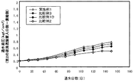
そこで、比較例1Dにおいて、第2の逆浸透装置の水回収率を次のように変動させながら比較例1Dと同様の処理を行って、第2の逆浸透装置の水回収率と詰まり(通水差圧)の関係を調査した。
(Example 1, Comparative Examples 2-3)
The second reverse osmosis device is normally operated at about 50 to 66%, and technically about 80% is the limit. However, the above findings suggest the possibility of exceeding this limit. That is, since the silica concentration naturally increases on the high concentration side, clogging may be suppressed by some interaction due to the coexistence of silica and a high-level component as described above.
Therefore, in Comparative Example 1D, the same process as in Comparative Example 1D was performed while changing the water recovery rate of the second reverse osmosis device as follows, and the water recovery rate and clogging (through the general flow rate of the second reverse osmosis device). The relationship of water differential pressure was investigated.
[比較例2]:比較例1Dとは、第2の逆浸透装置の水回収率を50%に変更した以外は同一の処理を行った。
[比較例3]:比較例1Dとは、第2の逆浸透装置の水回収率を90%に変更した以外は同一の処理を行った。
[実施例1]:比較例1Dとは、第2の逆浸透装置の水回収率を95%に変更した以外は同一の処理を行った。
[Comparative Example 2]: The same treatment as Comparative Example 1D was performed except that the water recovery rate of the second reverse osmosis device was changed to 50%.
[Comparative Example 3]: The same treatment as Comparative Example 1D was performed except that the water recovery rate of the second reverse osmosis device was changed to 90%.
[Example 1]: The same process as Comparative Example 1D was performed except that the water recovery rate of the second reverse osmosis device was changed to 95%.
この結果を図4に示した。図4に示したように、第2の逆浸透装置の水回収率を上げていくと、次第に通水差圧が上昇する傾向はあるが、詰まりの速度の上昇は水回収率の上昇に見合ったものではなく、特に、水回収率を90%程度まで上げても詰まりの程度は激しくないことが確認された。したがって、このような条件での運転においても、図1の純水製造装置は十分に実用可能であることが確認された。 The results are shown in FIG. As shown in FIG. 4, when the water recovery rate of the second reverse osmosis device is increased, the water flow differential pressure tends to increase gradually, but the increase in the clogging speed is commensurate with the increase in the water recovery rate. In particular, it was confirmed that the degree of clogging was not severe even when the water recovery rate was increased to about 90%. Accordingly, it was confirmed that the pure water production apparatus of FIG. 1 is sufficiently practical even in operation under such conditions.
このとき、第2の逆浸透装置の詰まりが激しい場合には、第2の逆浸透装置、又は第1の逆浸透装置の供給水にシリカ(水ガラス)を添加して、膜の詰まりを抑制するという運転も可能である。 At this time, when the clogging of the second reverse osmosis device is severe, silica (water glass) is added to the supply water of the second reverse osmosis device or the first reverse osmosis device to suppress clogging of the membrane. Driving is also possible.
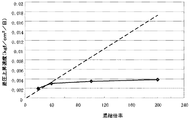
また、図4より、濃縮倍率と差圧上昇速度との関係を算出しまとめなおすと図5のように表すことができる。従来、概ね原点を通る直線(図5における点線)に近い傾向となることが予測され、実施不能と思われていたが、水回収率を上げても膜の詰まりがそれに比して大きくならない傾向が確認できた。なお、参考までに実施例1、比較例1D、比較例4で得られた透過水の水質について表4に示した。なお、比較例4は、比較例1Dと同様の装置で、第2の逆浸透装置の水回収率を98%まで向上させた場合の水質である。 Further, when the relationship between the concentration ratio and the differential pressure increase rate is calculated and summarized from FIG. 4, it can be expressed as shown in FIG. Previously, it was predicted that the trend would be close to a straight line that almost passes through the origin (dotted line in FIG. 5), and it seemed impossible to implement, but even if the water recovery rate was increased, the clogging of the membrane did not increase Was confirmed. For reference, the permeated water quality obtained in Example 1, Comparative Example 1D, and Comparative Example 4 is shown in Table 4. In addition, the comparative example 4 is a water quality | type at the time of improving the water recovery rate of a 2nd reverse osmosis apparatus to 98% by the apparatus similar to comparative example 1D.
比較例1Dの場合、図1のシステム全体での水回収率は、97.5%である。同様に、実施例1の場合には、99.5%である。したがって、排水率は、比較例2の場合、2.5%、実施例1の場合には、0.5%であり、排水の量が1/5程度に低減されるという効果があることが確認された。 In the case of Comparative Example 1D, the water recovery rate in the entire system of FIG. 1 is 97.5%. Similarly, in the case of Example 1, it is 99.5%. Therefore, the drainage rate is 2.5% in the case of Comparative Example 2 and 0.5% in the case of Example 1, and there is an effect that the amount of drainage is reduced to about 1/5. confirmed.
また、比較例1Dと実施例1では、同じポンプを使用して、水回収率のみを変えている。したがって、本発明を使用すると、水回収率を向上させる際、動力費を上げずに、水回収率を上げることが可能という効果が得られることが確認された。 In Comparative Example 1D and Example 1, only the water recovery rate is changed using the same pump. Therefore, it has been confirmed that when the present invention is used, it is possible to increase the water recovery rate without increasing the power cost when the water recovery rate is improved.
(数値範囲の検討)
実施例1、比較例1D、比較例4を比較すると、第2の逆浸透膜の水回収率は、95%の場合に、第2の逆浸透装置の透過水43のホウ素濃度が被処理水のホウ素濃度と同じになり、第1の逆浸透装置の透過水33の水質(ホウ素濃度)は、比較例1Dと同等であった。しかし比較例4の場合には、第2の逆浸透装置の透過水43のホウ素濃度が被処理水の濃度より高くなり、その結果、第1の逆浸透装置の透過水水質も悪化した。したがって、これらの条件のうち、第1の逆浸透装置で製造する純水の水質を維持し、第2の逆浸透装置の透過水を循環再利用して水回収率を向上させるには、第2の逆浸透装置の水回収率が95%の場合が最善であることが確認できた。
(Examination of numerical range)
Comparing Example 1, Comparative Example 1D, and Comparative Example 4, when the water recovery rate of the second reverse osmosis membrane is 95%, the boron concentration of the permeated
なお、ホウ素の除去率に注目する理由は、純水装置の後段における除去が最も困難な物質であることが理由である。また、実施例1、比較例1D、比較例4においては、第1の逆浸透装置の水回収率は90%であるが、第1の逆浸透装置の水回収率を変えた場合には、第2の逆浸透装置の水回収率の最善の値も変動すると考えられる。 The reason for paying attention to the removal rate of boron is that it is the most difficult substance to remove in the subsequent stage of the pure water apparatus. Moreover, in Example 1, Comparative Example 1D, and Comparative Example 4, the water recovery rate of the first reverse osmosis device is 90%, but when the water recovery rate of the first reverse osmosis device is changed, It is believed that the best value of the water recovery rate of the second reverse osmosis device will also vary.
そこで、同様にして、第1の逆浸透装置の水回収率を50%(図示せず)、85%、93%、95%、98%とした場合の第2の逆浸透装置の透過水43と被処理水のホウ素濃度が同じになる条件として、第2の逆浸透装置の水回収率を参照しながら確認した。その結果を図6に示した。
Therefore, similarly, the permeated
図6より、第2の逆浸透装置の透過水の水質と被処理水の水質が同等となる点からは、
Y=100−50.5/(100−X)
(ただし、X:逆浸透装置1の水回収率(%)、Y:逆浸透装置2の水回収率(%)を表す。)にて運転することが最善であることがわかった。
From FIG. 6, from the point that the quality of the permeated water of the second reverse osmosis device and the quality of the treated water are equivalent,
Y = 100-50.5 / (100-X)
It was found that it is best to operate at (where X: water recovery rate (%) of
次に、図6の各点における第1の逆浸透装置の透過水水質(ホウ素濃度)と第1の逆浸透装置の水回収率との関係をまとめると図7のようになる。 Next, FIG. 7 summarizes the relationship between the permeated water quality (boron concentration) of the first reverse osmosis device and the water recovery rate of the first reverse osmosis device at each point in FIG.
図7から、第1の逆浸透装置の水回収率が95%を超えると、第1の逆浸透装置の透過水のホウ素濃度が急激に増加することから、第1の逆浸透装置の透過水のホウ素濃度の観点からは、第1の逆浸透装置の水回収率は95%以下であることが良いことがわかる。また、本発明の目的は、水回収率の向上なので、第1の逆浸透装置の水回収率は90%以下にすることは好ましくない。 From FIG. 7, when the water recovery rate of the first reverse osmosis device exceeds 95%, the boron concentration of the permeated water of the first reverse osmosis device increases rapidly, so that the permeated water of the first reverse osmosis device. From the viewpoint of the boron concentration, it can be seen that the water recovery rate of the first reverse osmosis device is preferably 95% or less. Further, since the object of the present invention is to improve the water recovery rate, it is not preferable to set the water recovery rate of the first reverse osmosis device to 90% or less.
次に、図6に示した最善の水回収率の条件から、第2の逆浸透装置の水回収率のみを上げた場合に関して検討した。このとき、第1の逆浸透装置の水回収率を90%、95%とした場合の第2の逆浸透膜装置の水回収率と第1の逆浸透膜装置の透過水のホウ素濃度との関係を図8に示した。 Next, the case where only the water recovery rate of the 2nd reverse osmosis apparatus was raised from the conditions of the best water recovery rate shown in FIG. 6 was examined. At this time, the water recovery rate of the second reverse osmosis membrane device and the boron concentration of the permeated water of the first reverse osmosis membrane device when the water recovery rate of the first reverse osmosis device is 90% and 95%. The relationship is shown in FIG.
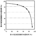
図8より、図6にて示した最善の水回収率よりも第2の逆浸透装置の水回収率を向上させることが可能であることがわかるが、水回収率が97%を超えると第1の逆浸透装置の透過水のホウ素濃度が急激に増加して水質を悪化させるので、第2の逆浸透装置の水回収率は97%が限界であることがわかった。 FIG. 8 shows that it is possible to improve the water recovery rate of the second reverse osmosis device from the best water recovery rate shown in FIG. Since the boron concentration of the permeated water of No. 1 reverse osmosis device suddenly increased and the water quality deteriorated, it was found that the water recovery rate of the second reverse osmosis device was 97%.
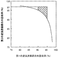
以上の検討結果から、第1の逆浸透装置及び第2の逆浸透装置の水回収率は図9で示した斜線の範囲の条件に設定することが最善であることがわかった。 From the above examination results, it was found that it is best to set the water recovery rates of the first reverse osmosis device and the second reverse osmosis device to the conditions in the shaded range shown in FIG.
(実施例2)
実施例1の装置において、第2の逆浸透装置を、日東電工社製、商品名:NTR−759HRに変更した以外は、同一の処理を行った。この場合の水質は表5に示した通りであり、表4の場合とほぼ同様であった。
(Example 2)
In the apparatus of Example 1, the same process was performed except that the second reverse osmosis apparatus was changed to Nitto Denko Corporation, trade name: NTR-759HR. The water quality in this case was as shown in Table 5 and was almost the same as in Table 4.
(実施例3)
実施例1の装置において、第2の逆浸透装置を、日東電工社製、商品名:ES−20に変更した以外は同一の処理を行った。この場合の水質は表6に示した通りであり、表4の場合とほぼ同様であった。
(Example 3)
In the apparatus of Example 1, the same treatment was performed except that the second reverse osmosis apparatus was changed to Nitto Denko Corporation, trade name: ES-20. The water quality in this case was as shown in Table 6 and was almost the same as in Table 4.
以上より、第1の逆浸透装置及び第2の逆浸透装置の水回収率を、これまで水質が極めて悪化したり、逆浸透装置の膜が詰まったりと考えられていた条件であっても、それぞれ所定の範囲とすることにより、製造する純水の水質を極端に低下させることなく、純水製造装置全体の水回収率を極めて効率的に行いながら、純水を製造することができることがわかった。 From the above, the water recovery rate of the first reverse osmosis device and the second reverse osmosis device, even under conditions where water quality has so far been extremely deteriorated or the membrane of the reverse osmosis device is clogged, It can be seen that, by setting each to a predetermined range, it is possible to produce pure water while extremely efficiently performing the water recovery rate of the entire pure water production apparatus without extremely reducing the quality of the pure water produced. It was.
1…カチオン交換樹脂装置、2…脱気装置、3…第1の逆浸透装置、4…第2の逆浸透装置、5…透過水ピット、11…被処理水ピット、12,32,42…ポンプ、41…濃縮水ピット、43…返送配管
DESCRIPTION OF
Claims (2)
前記第1の逆浸透装置における水回収率を90〜95%とし、前記第2の逆浸透装置における水回収率を97%以下で、かつ、次式(1)
Y≧100−50.5/(100−X) …(1)
(ただし、Yは第2の逆浸透装置の水回収率(%)、Xは第1の逆浸透装置の水回収率(%)を表す。)の関係を満たす範囲とすることを特徴とする純水製造方法。 The raw water is passed through an H-type cation exchange resin tower, degassed with a degassing device, and then passed through the first reverse osmosis device under alkaline conditions of pH 10 or higher to produce pure water. Pure water that passes alkaline concentrated water discharged from the first reverse osmosis device through a separately provided second reverse osmosis device and returns the permeate to the front stage of the first reverse osmosis device. A water production method,
The water recovery rate in the first reverse osmosis device is 90 to 95%, the water recovery rate in the second reverse osmosis device is 97% or less, and the following formula (1)
Y ≧ 100-50.5 / (100-X) (1)
(Where Y represents the water recovery rate (%) of the second reverse osmosis device, and X represents the water recovery rate (%) of the first reverse osmosis device). Pure water production method.
Priority Applications (1)
| Application Number | Priority Date | Filing Date | Title |
|---|---|---|---|
| JP2008191171A JP4917581B2 (en) | 2008-07-24 | 2008-07-24 | Pure water production method |
Applications Claiming Priority (1)
| Application Number | Priority Date | Filing Date | Title |
|---|---|---|---|
| JP2008191171A JP4917581B2 (en) | 2008-07-24 | 2008-07-24 | Pure water production method |
Publications (2)
| Publication Number | Publication Date |
|---|---|
| JP2010023006A true JP2010023006A (en) | 2010-02-04 |
| JP4917581B2 JP4917581B2 (en) | 2012-04-18 |
Family
ID=41729347
Family Applications (1)
| Application Number | Title | Priority Date | Filing Date |
|---|---|---|---|
| JP2008191171A Active JP4917581B2 (en) | 2008-07-24 | 2008-07-24 | Pure water production method |
Country Status (1)
| Country | Link |
|---|---|
| JP (1) | JP4917581B2 (en) |
Cited By (12)
| Publication number | Priority date | Publication date | Assignee | Title |
|---|---|---|---|---|
| JP2013105536A (en) * | 2011-11-10 | 2013-05-30 | Toyota Motor Corp | Lithium secondary battery, and method for manufacturing the same |
| JP2013535322A (en) * | 2010-07-26 | 2013-09-12 | ビーダブリューティー アクティエンゲゼルシャフト | Method and system for treating water |
| JP2013233489A (en) * | 2012-05-07 | 2013-11-21 | Miura Co Ltd | Water treatment method, and water treatment system |
| CN107459157A (en) * | 2016-06-02 | 2017-12-12 | 博乐宝科技有限公司 | Intelligent water-saving type anti-penetration water purifier and its process for purifying water with reflux |
| WO2018043462A1 (en) * | 2016-08-31 | 2018-03-08 | 東レ株式会社 | Ion exchange fiber, water purification filter and water treatment method |
| CN107789857A (en) * | 2016-08-31 | 2018-03-13 | 温州市大成药机制造有限公司 | A kind of High Pressure Difference cold extraction concentrates unit |
| CN108726638A (en) * | 2018-07-02 | 2018-11-02 | 珠海格力电器股份有限公司 | The control method of water treatment system, purifying drinking appliance and water treatment system |
| CN110498480A (en) * | 2019-09-21 | 2019-11-26 | 佛山市云米电器科技有限公司 | A kind of split type reverse osmosis filter element device and a kind of water purifier |
| CN110498479A (en) * | 2019-09-21 | 2019-11-26 | 佛山市云米电器科技有限公司 | A kind of reverse osmosis filter element device of dual-membrane type and a kind of water purifier |
| CN111003765A (en) * | 2019-12-31 | 2020-04-14 | 佛山市云米电器科技有限公司 | Water purification system and water purifier with constant proportion of pure wastewater |
| JP2021045701A (en) * | 2019-09-17 | 2021-03-25 | 野村マイクロ・サイエンス株式会社 | Ultrapure water production system and ultrapure water production method |
| CN115159622A (en) * | 2022-06-15 | 2022-10-11 | 华能八〇三热电有限公司 | Reverse osmosis is circuit connector for dense water recovery unit |
Citations (2)
| Publication number | Priority date | Publication date | Assignee | Title |
|---|---|---|---|---|
| JP2000271570A (en) * | 1999-03-25 | 2000-10-03 | Kurita Water Ind Ltd | Production of pure water |
| JP2002192152A (en) * | 2000-12-25 | 2002-07-10 | Nomura Micro Sci Co Ltd | Method and apparatus for water treatment |
-
2008
- 2008-07-24 JP JP2008191171A patent/JP4917581B2/en active Active
Patent Citations (2)
| Publication number | Priority date | Publication date | Assignee | Title |
|---|---|---|---|---|
| JP2000271570A (en) * | 1999-03-25 | 2000-10-03 | Kurita Water Ind Ltd | Production of pure water |
| JP2002192152A (en) * | 2000-12-25 | 2002-07-10 | Nomura Micro Sci Co Ltd | Method and apparatus for water treatment |
Cited By (16)
| Publication number | Priority date | Publication date | Assignee | Title |
|---|---|---|---|---|
| JP2013535322A (en) * | 2010-07-26 | 2013-09-12 | ビーダブリューティー アクティエンゲゼルシャフト | Method and system for treating water |
| JP2013105536A (en) * | 2011-11-10 | 2013-05-30 | Toyota Motor Corp | Lithium secondary battery, and method for manufacturing the same |
| JP2013233489A (en) * | 2012-05-07 | 2013-11-21 | Miura Co Ltd | Water treatment method, and water treatment system |
| CN107459157A (en) * | 2016-06-02 | 2017-12-12 | 博乐宝科技有限公司 | Intelligent water-saving type anti-penetration water purifier and its process for purifying water with reflux |
| WO2018043462A1 (en) * | 2016-08-31 | 2018-03-08 | 東レ株式会社 | Ion exchange fiber, water purification filter and water treatment method |
| CN107789857A (en) * | 2016-08-31 | 2018-03-13 | 温州市大成药机制造有限公司 | A kind of High Pressure Difference cold extraction concentrates unit |
| CN108726638A (en) * | 2018-07-02 | 2018-11-02 | 珠海格力电器股份有限公司 | The control method of water treatment system, purifying drinking appliance and water treatment system |
| CN108726638B (en) * | 2018-07-02 | 2023-07-21 | 珠海格力电器股份有限公司 | Water treatment system, water purifying and drinking machine and control method of water treatment system |
| JP7261711B2 (en) | 2019-09-17 | 2023-04-20 | 野村マイクロ・サイエンス株式会社 | Ultrapure water production system and ultrapure water production method |
| JP2021045701A (en) * | 2019-09-17 | 2021-03-25 | 野村マイクロ・サイエンス株式会社 | Ultrapure water production system and ultrapure water production method |
| CN110498479A (en) * | 2019-09-21 | 2019-11-26 | 佛山市云米电器科技有限公司 | A kind of reverse osmosis filter element device of dual-membrane type and a kind of water purifier |
| CN110498480A (en) * | 2019-09-21 | 2019-11-26 | 佛山市云米电器科技有限公司 | A kind of split type reverse osmosis filter element device and a kind of water purifier |
| CN110498480B (en) * | 2019-09-21 | 2024-03-15 | 广东栗子科技有限公司 | Split type reverse osmosis filter element device and purifier |
| CN111003765A (en) * | 2019-12-31 | 2020-04-14 | 佛山市云米电器科技有限公司 | Water purification system and water purifier with constant proportion of pure wastewater |
| CN115159622A (en) * | 2022-06-15 | 2022-10-11 | 华能八〇三热电有限公司 | Reverse osmosis is circuit connector for dense water recovery unit |
| CN115159622B (en) * | 2022-06-15 | 2024-04-12 | 华能八〇三热电有限公司 | Circuit connector for reverse osmosis concentrated water recovery device |
Also Published As
| Publication number | Publication date |
|---|---|
| JP4917581B2 (en) | 2012-04-18 |
Similar Documents
| Publication | Publication Date | Title |
|---|---|---|
| JP4917581B2 (en) | Pure water production method | |
| TWI504572B (en) | A method for treating water for activated carbon, a method for treating water containing organic matter, and a treatment device | |
| TWI461372B (en) | Processing method and processing device containing organic matter drainage | |
| KR101464022B1 (en) | Method and apparatus for treating water containing organic matter | |
| KR20140000268A (en) | Method and apparatus for treatment of water containing organic material | |
| JP5211518B2 (en) | Organic substance removing method and apparatus | |
| JP2008259961A (en) | Electrodeionizing apparatus and its operation method | |
| JPH11244853A (en) | Production of pure water | |
| WO2020184045A1 (en) | Apparatus for removing boron, method for removing boron, apparatus for producing pure water and method for producing pure water | |
| JP2007307561A (en) | High-purity water producing apparatus and method | |
| JP4850467B2 (en) | Cleaning method for membrane deaerator | |
| JP3137831B2 (en) | Membrane processing equipment | |
| JPWO2008059824A1 (en) | Water treatment apparatus and water treatment method | |
| JP2005230731A (en) | Method and apparatus for water treatment | |
| JP2716655B2 (en) | Cleaning method for reverse osmosis membrane device | |
| JP5135697B2 (en) | Surfactant-containing wastewater treatment method | |
| WO2021215099A1 (en) | Waste water treatment method, ultrapure water production method, and waste water treatment apparatus | |
| WO2020184044A1 (en) | Pure-water production device and pure-water production method | |
| JP3906855B2 (en) | Method and apparatus for treating wastewater containing organic matter and oxidizing agent | |
| JP4208270B2 (en) | Pure water production method | |
| JP2008036605A (en) | Apparatus for producing purified water and method for producing purified water | |
| WO2017145419A1 (en) | Cleaning method for ultrapure water production system | |
| JP2006122908A (en) | Pure water producing method | |
| JP6968682B2 (en) | Manufacturing method of permeated water, water treatment device and operation method of the water treatment device | |
| JP6561448B2 (en) | Method and apparatus for electrodeionization treatment of vanadium-containing water |
Legal Events
| Date | Code | Title | Description |
|---|---|---|---|
| A621 | Written request for application examination |
Free format text: JAPANESE INTERMEDIATE CODE: A621 Effective date: 20110622 |
|
| A977 | Report on retrieval |
Free format text: JAPANESE INTERMEDIATE CODE: A971007 Effective date: 20111226 |
|
| TRDD | Decision of grant or rejection written | ||
| A01 | Written decision to grant a patent or to grant a registration (utility model) |
Free format text: JAPANESE INTERMEDIATE CODE: A01 Effective date: 20120110 |
|
| A01 | Written decision to grant a patent or to grant a registration (utility model) |
Free format text: JAPANESE INTERMEDIATE CODE: A01 |
|
| A61 | First payment of annual fees (during grant procedure) |
Free format text: JAPANESE INTERMEDIATE CODE: A61 Effective date: 20120126 |
|
| FPAY | Renewal fee payment (event date is renewal date of database) |
Free format text: PAYMENT UNTIL: 20150203 Year of fee payment: 3 |
|
| R150 | Certificate of patent or registration of utility model |
Ref document number: 4917581 Country of ref document: JP Free format text: JAPANESE INTERMEDIATE CODE: R150 |
|
| R250 | Receipt of annual fees |
Free format text: JAPANESE INTERMEDIATE CODE: R250 |
|
| R250 | Receipt of annual fees |
Free format text: JAPANESE INTERMEDIATE CODE: R250 |
|
| R250 | Receipt of annual fees |
Free format text: JAPANESE INTERMEDIATE CODE: R250 |
|
| R250 | Receipt of annual fees |
Free format text: JAPANESE INTERMEDIATE CODE: R250 |
|
| R250 | Receipt of annual fees |
Free format text: JAPANESE INTERMEDIATE CODE: R250 |
|
| R250 | Receipt of annual fees |
Free format text: JAPANESE INTERMEDIATE CODE: R250 |
|
| R250 | Receipt of annual fees |
Free format text: JAPANESE INTERMEDIATE CODE: R250 |
|
| R250 | Receipt of annual fees |
Free format text: JAPANESE INTERMEDIATE CODE: R250 |
|
| R250 | Receipt of annual fees |
Free format text: JAPANESE INTERMEDIATE CODE: R250 |
|
| R250 | Receipt of annual fees |
Free format text: JAPANESE INTERMEDIATE CODE: R250 |