JP2010019294A - 車両用遊星歯車装置のキャリヤおよびその製造方法 - Google Patents
車両用遊星歯車装置のキャリヤおよびその製造方法 Download PDFInfo
- Publication number
- JP2010019294A JP2010019294A JP2008178501A JP2008178501A JP2010019294A JP 2010019294 A JP2010019294 A JP 2010019294A JP 2008178501 A JP2008178501 A JP 2008178501A JP 2008178501 A JP2008178501 A JP 2008178501A JP 2010019294 A JP2010019294 A JP 2010019294A
- Authority
- JP
- Japan
- Prior art keywords
- carrier
- cover
- planetary gear
- sintering
- carrier cover
- Prior art date
- Legal status (The legal status is an assumption and is not a legal conclusion. Google has not performed a legal analysis and makes no representation as to the accuracy of the status listed.)
- Granted
Links
Images


Classifications
-
- F—MECHANICAL ENGINEERING; LIGHTING; HEATING; WEAPONS; BLASTING
- F16—ENGINEERING ELEMENTS AND UNITS; GENERAL MEASURES FOR PRODUCING AND MAINTAINING EFFECTIVE FUNCTIONING OF MACHINES OR INSTALLATIONS; THERMAL INSULATION IN GENERAL
- F16H—GEARING
- F16H57/00—General details of gearing
- F16H57/08—General details of gearing of gearings with members having orbital motion
- F16H57/082—Planet carriers
Landscapes
- Engineering & Computer Science (AREA)
- General Engineering & Computer Science (AREA)
- Mechanical Engineering (AREA)
- Hybrid Electric Vehicles (AREA)
- General Details Of Gearings (AREA)
- Powder Metallurgy (AREA)
Abstract
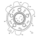
【解決手段】キャリヤカバー54のフランジ部80の外周部から軸心C1を中心とする半径方向外方へ突き出す突部82の先端において、外向きに開くように設けられた矩形状断面の加工基準溝78が設けられていることから、キャリヤカバー54の内周側のサンギヤS2とリングギヤR2との間の位置に、貫通穴76を加工するための加工基準としての貫通孔を設ける必要がないので、複数のピニオンP2と、その複数のピニオンP2間においてキャリヤ本体52およびキャリヤカバー54を相互に結合するための複数の結合部64とを、最小限の隙間を以って配置させることができるので、必要強度を確保しつつ可及的に小型軽量化されたキャリヤCA2が得られる。
【選択図】図5
Description
50:キャリヤピン
52:キャリヤ本体
54:キャリヤカバー
58、76:貫通穴
78:加工基準溝
CA1、CA2:キャリヤ
P2:ピニオン
R1、R2:リングギヤ
S1、S2:サンギヤ
p1:キャリヤカバー焼結工程
p2:キャリヤ本体焼結工程
p3:ろう付け工程
p4:機械加工工程
Claims (2)
- サンギヤとリングギヤとの間で両者に噛み合うピニオンを回転可能に支持するキャリヤピンの両端を支持するためのキャリヤ本体およびキャリヤカバーを備える車両用遊星歯車装置のキャリヤであって、
前記キャリヤカバーの外周部に、前記キャリヤピンを嵌め入れるための貫通穴を加工するための外向きに開く加工基準溝が設けられていることを特徴とする車両用遊星歯車装置のキャリヤ。 - サンギヤとリングギヤとの間で両者に噛み合うピニオンを回転可能に支持するキャリヤピンの両端を支持するためのキャリヤ本体およびキャリヤカバーを備える車両用遊星歯車装置のキャリヤの製造方法であって、
外向きに開く加工基準溝を外周部に有する形状で、金属粉体から焼結型を用いて前記キャリヤカバーを焼結により成形するキャリヤカバー焼結工程と、
金属粉体から焼結型を用いて前記キャリヤ本体を焼結により成形するキャリヤ本体焼結工程と、
焼結により得られた前記キャリヤ本体およびキャリヤカバーをろう付けにより相互に結合するろう付け工程と、
相互に結合されたキャリヤ本体およびキャリヤカバーに、該キャリヤカバーの外周部に設けられた加工基準溝を基準として前記キャリヤピンを嵌め入れる貫通穴を機械加工により形成する機械加工工程と
を、含むことを特徴とする車両用遊星歯車装置のキャリヤの製造方法。
Priority Applications (1)
| Application Number | Priority Date | Filing Date | Title |
|---|---|---|---|
| JP2008178501A JP4992840B2 (ja) | 2008-07-08 | 2008-07-08 | 車両用遊星歯車装置のキャリヤおよびその製造方法 |
Applications Claiming Priority (1)
| Application Number | Priority Date | Filing Date | Title |
|---|---|---|---|
| JP2008178501A JP4992840B2 (ja) | 2008-07-08 | 2008-07-08 | 車両用遊星歯車装置のキャリヤおよびその製造方法 |
Publications (2)
| Publication Number | Publication Date |
|---|---|
| JP2010019294A true JP2010019294A (ja) | 2010-01-28 |
| JP4992840B2 JP4992840B2 (ja) | 2012-08-08 |
Family
ID=41704413
Family Applications (1)
| Application Number | Title | Priority Date | Filing Date |
|---|---|---|---|
| JP2008178501A Active JP4992840B2 (ja) | 2008-07-08 | 2008-07-08 | 車両用遊星歯車装置のキャリヤおよびその製造方法 |
Country Status (1)
| Country | Link |
|---|---|
| JP (1) | JP4992840B2 (ja) |
Cited By (2)
| Publication number | Priority date | Publication date | Assignee | Title |
|---|---|---|---|---|
| JP2016539297A (ja) * | 2013-09-27 | 2016-12-15 | ジーケーエヌ シンター メタルズ、エル・エル・シー | 遊星歯車キャリアアセンブリおよび関連する作成方法 |
| CN107228185A (zh) * | 2016-03-24 | 2017-10-03 | 扬州保来得科技实业有限公司 | 一种汽车变速器输入排行星架 |
Citations (2)
| Publication number | Priority date | Publication date | Assignee | Title |
|---|---|---|---|---|
| JPH09229146A (ja) * | 1996-02-28 | 1997-09-02 | Aisin Aw Co Ltd | キャリヤ組立体 |
| JP2000109907A (ja) * | 1998-10-05 | 2000-04-18 | Sumitomo Electric Ind Ltd | 鑞付け接合焼結部品及び同部品の製造方法 |
-
2008
- 2008-07-08 JP JP2008178501A patent/JP4992840B2/ja active Active
Patent Citations (2)
| Publication number | Priority date | Publication date | Assignee | Title |
|---|---|---|---|---|
| JPH09229146A (ja) * | 1996-02-28 | 1997-09-02 | Aisin Aw Co Ltd | キャリヤ組立体 |
| JP2000109907A (ja) * | 1998-10-05 | 2000-04-18 | Sumitomo Electric Ind Ltd | 鑞付け接合焼結部品及び同部品の製造方法 |
Cited By (2)
| Publication number | Priority date | Publication date | Assignee | Title |
|---|---|---|---|---|
| JP2016539297A (ja) * | 2013-09-27 | 2016-12-15 | ジーケーエヌ シンター メタルズ、エル・エル・シー | 遊星歯車キャリアアセンブリおよび関連する作成方法 |
| CN107228185A (zh) * | 2016-03-24 | 2017-10-03 | 扬州保来得科技实业有限公司 | 一种汽车变速器输入排行星架 |
Also Published As
| Publication number | Publication date |
|---|---|
| JP4992840B2 (ja) | 2012-08-08 |
Similar Documents
| Publication | Publication Date | Title |
|---|---|---|
| US10630140B2 (en) | Electric vehicle drive system | |
| JP5246466B2 (ja) | ハイブリッド駆動装置 | |
| CN106794749B (zh) | 变速器装置 | |
| JP5303970B2 (ja) | キャリア組立体 | |
| JP6327396B2 (ja) | 遊星歯車機構 | |
| WO2020149411A1 (ja) | 車両用駆動装置 | |
| JP6160478B2 (ja) | ハイブリッド車両の駆動装置 | |
| JP2005312121A (ja) | 遊星歯車変速機を有する回転電機及びそれを構成する回転子支持軸の製造方法 | |
| US20100231064A1 (en) | Balance ring for a vehicular electric machine | |
| CN103373224A (zh) | 用于汽车的驱动设备 | |
| EP3783778A1 (en) | Dynamo-electric machine, and drive device for vehicle comprising dynamo-electric machine | |
| EP2210006B1 (fr) | Machine electrique comportant une liaison elastique avec un arbre primaire d'une boite de vitesses | |
| JP4992840B2 (ja) | 車両用遊星歯車装置のキャリヤおよびその製造方法 | |
| US7220207B2 (en) | Differential apparatus | |
| US7534189B2 (en) | Planetary gear train and driving unit having the same | |
| JP2019052685A (ja) | 車両用駆動装置 | |
| JP5141376B2 (ja) | 動力伝達装置 | |
| CN107709811A (zh) | 带有扭转减振器的变速器 | |
| JP2017198238A (ja) | デファレンシャルギヤケース | |
| JP2004116737A (ja) | 遊星歯車装置およびパワートレーン | |
| US12546386B2 (en) | Gearbox arrangement comprising a stepped planetary reduction, a differential, and an electrically operable axle drive train | |
| JP7800046B2 (ja) | 駆動装置 | |
| US12179570B2 (en) | Motor attachment structure for electric vehicle | |
| JP2003148595A (ja) | 支持穴の加工方法および支持構造 | |
| JP2017116092A (ja) | 差動装置 |
Legal Events
| Date | Code | Title | Description |
|---|---|---|---|
| A621 | Written request for application examination |
Free format text: JAPANESE INTERMEDIATE CODE: A621 Effective date: 20101012 |
|
| A977 | Report on retrieval |
Free format text: JAPANESE INTERMEDIATE CODE: A971007 Effective date: 20111222 |
|
| A131 | Notification of reasons for refusal |
Free format text: JAPANESE INTERMEDIATE CODE: A131 Effective date: 20120110 |
|
| A521 | Written amendment |
Free format text: JAPANESE INTERMEDIATE CODE: A523 Effective date: 20120201 |
|
| TRDD | Decision of grant or rejection written | ||
| A01 | Written decision to grant a patent or to grant a registration (utility model) |
Free format text: JAPANESE INTERMEDIATE CODE: A01 Effective date: 20120410 |
|
| A01 | Written decision to grant a patent or to grant a registration (utility model) |
Free format text: JAPANESE INTERMEDIATE CODE: A01 |
|
| A61 | First payment of annual fees (during grant procedure) |
Free format text: JAPANESE INTERMEDIATE CODE: A61 Effective date: 20120423 |
|
| FPAY | Renewal fee payment (event date is renewal date of database) |
Free format text: PAYMENT UNTIL: 20150518 Year of fee payment: 3 |
|
| R151 | Written notification of patent or utility model registration |
Ref document number: 4992840 Country of ref document: JP Free format text: JAPANESE INTERMEDIATE CODE: R151 |
|
| FPAY | Renewal fee payment (event date is renewal date of database) |
Free format text: PAYMENT UNTIL: 20150518 Year of fee payment: 3 |