JP2010018404A - Safe, bill processor, and bill handling device - Google Patents
Safe, bill processor, and bill handling device Download PDFInfo
- Publication number
- JP2010018404A JP2010018404A JP2008181508A JP2008181508A JP2010018404A JP 2010018404 A JP2010018404 A JP 2010018404A JP 2008181508 A JP2008181508 A JP 2008181508A JP 2008181508 A JP2008181508 A JP 2008181508A JP 2010018404 A JP2010018404 A JP 2010018404A
- Authority
- JP
- Japan
- Prior art keywords
- banknote
- bill
- return
- guide
- banknotes
- Prior art date
- Legal status (The legal status is an assumption and is not a legal conclusion. Google has not performed a legal analysis and makes no representation as to the accuracy of the status listed.)
- Granted
Links
- 238000000034 method Methods 0.000 description 3
- 238000009825 accumulation Methods 0.000 description 2
- 238000000151 deposition Methods 0.000 description 2
- 238000010586 diagram Methods 0.000 description 2
- 238000003780 insertion Methods 0.000 description 2
- 230000037431 insertion Effects 0.000 description 2
- 238000001514 detection method Methods 0.000 description 1
- 238000003825 pressing Methods 0.000 description 1
- 238000011084 recovery Methods 0.000 description 1
Images

Abstract
Description
本発明は例えば紙幣を入金する機能を備えた各種自動販売機、入出金装置、両替機等の紙幣取扱装置に装備される紙幣処理装置の改良に関し、特に紙幣返却時に利用者が実際に投入した紙幣を確実に把握して必要枚数だけを現物返却することができるようにした紙幣収納庫、紙幣処理装置、及び紙幣取扱装置に関する。 The present invention relates to an improvement of a banknote handling apparatus equipped in a banknote handling apparatus such as various vending machines having a function of depositing banknotes, a depositing / dispensing apparatus, a money changer, and the like. The present invention relates to a banknote storage, a banknote handling apparatus, and a banknote handling apparatus that can reliably grasp banknotes and return only the necessary number of sheets.
投入された紙幣を受け入れる入金機能や、釣り銭や払出し金として紙幣を払い出す出金機能を備えた紙幣処理装置は各種自動販売機、入出金装置、両替機等の紙幣取扱装置に装備されており、この紙幣処理装置には投入された紙幣を保管するための紙幣収納庫が装備されている。
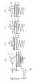
図3は従来の紙幣収納庫の概略構成、及び動作を示す図であり、この紙幣収納庫100は、正逆転可能な搬送部材(ローラや搬送ベルト)を備えた図示しない紙幣導入・返却搬送路(紙面の奥方に位置する)から導入されてきた紙幣Pを積載する昇降自在な積載台101と、積載台101の上方において昇降自在に支持され且つ導入されてきた紙幣の幅方向両端縁下面を保持するガイド片対(フォーク)102と、ガイド片対102により幅方向両端縁を保持された紙幣Pの中間部を相対的に押し下げてガイド片対を越えて積載台101上に移載する高さ固定の紙幣ガイド103と、紙幣ガイド103により回転自在に支持されて回転駆動される繰出しローラ104と、これらを駆動する駆動源と、該駆動源を制御する制御手段と、を備えている。ガイド片対102は、一枚ずつ投入された紙幣のみならず、複数枚一括して投入された紙幣も支持する。
図3(a)は紙幣導入時(入金時)の状態を示しており、図示しない紙幣導入・返却搬送路から長手方向一端部を先頭にして導入されてきた紙幣Pは紙幣受け入れ位置にあるガイド片対102の上面に載置される。この時、ガイド片対102は積載台101上に積載された紙幣P1上に接触して積載台(バネ101aにより上方に付勢されている)を最下降位置まで押し下げた状態で待機しており、紙幣ガイド103との間に紙幣の導入を妨げることがない程度の空間が形成されている。ここで利用者との取引がすべて終了すると、ガイド片対102は、(a)の最下降位置から(c)の最上昇位置まで停止することなく移動する。このときガイド片対102は(a)→(b)→(c)に示すように連続的に移動するので相対的に紙幣ガイド103がガイド片対102の中央空間内を通過することとなり、ガイド片対102上に載置された全ての紙幣Pを積載台101上(既推積紙幣P1の上面)に一括して移載することができる。
A banknote handling device with a deposit function for receiving inserted banknotes and a withdrawal function for dispensing banknotes as change or withdrawal is equipped in banknote handling devices such as various vending machines, deposit and withdrawal devices, and money changers. The banknote handling apparatus is equipped with a banknote storage for storing inserted banknotes.
FIG. 3 is a diagram showing a schematic configuration and operation of a conventional banknote storage, and this
FIG. 3A shows a state at the time of banknote introduction (payment), and a banknote P introduced from a banknote introduction / return conveyance path (not shown) with one end in the longitudinal direction at the head is a guide at the banknote receiving position. It is placed on the upper surface of the
ところで、利用者が紙幣を投入した後に返却ボタン(リジェクトボタン)をオンした場合には、紙幣処理装置の制御手段は投入された紙幣枚数を把握しているため、当該枚数分の紙幣を利用者に返却する動作を実施する。返却動作においては、ガイド片対102が(c)の最上昇位置に移動した状態で紙幣ガイドにより支持された繰出しローラ104が積載台上の紙幣P1の上面と圧接し、この状態で繰出しローラを戻し方向に回転駆動することにより紙幣導入・返却搬送路から返却することができる。
しかし、返却ボタンのオンにより返却動作を行っている過程でジャムが発生するなどして装置が停止した場合に呼び出された管理者が装置内部を確認したとしても利用者によって何枚の紙幣が投入されたのかを直ちに判別することができない。これは、(c)に示すように投入された紙幣は全て一旦積載台101上に移載されるため、返却のために繰出しローラ104が積載台101上の紙幣P1の上面と圧接した時点では、何枚の紙幣が当該利用者によって投入された紙幣であるかを目視により判別できる状態にはないためである。実際の投入枚数を正確に確認するにはログデータ解析することが必要であるが、停止した装置を再起動してログデータを読み出し解析するには時間を要するため、返却を求める利用者に対する迅速な対応が困難となる。
そのため、管理者は利用者に返却すべき紙幣枚数について利用者の申告に依存せねばならず、利用者の申告枚数よりも実際の投入枚数の方がよりも少ない場合であっても、申告枚数を返却せざるを得ないことがあった。
即ち、利用者の申告枚数と実際の投入枚数との整合性を正しく検証するにも紙幣処理装置のログデータを解析する必要があり、その為には手数と時間を要するため、利用者への速やかな返却が不可能となったり、自販機の稼働率を低下させる原因となっていた。
上記の如き構成を備えた紙幣処理装置として例えば特許文献1に開示されたものがあるが、同様の欠点を備えている。
However, even if the administrator who is called when the device is stopped due to a jam or the like during the return operation by turning on the return button checks the inside of the device, how many banknotes are inserted by the user It is not possible to immediately determine whether it has been done. This is because, as shown in (c), all the inserted bills are once transferred onto the stacking table 101, and therefore when the
Therefore, the administrator must rely on the user's declaration regarding the number of banknotes to be returned to the user, even if the actual number inserted is less than the user's declaration. I had to return it.
That is, it is necessary to analyze the log data of the banknote processing apparatus in order to correctly verify the consistency between the number of declared users and the actual number of inserted sheets, and this requires time and effort. Prompt return was impossible, and the operating rate of the vending machine was reduced.
As a banknote processing apparatus having the above configuration, for example, there is one disclosed in Patent Document 1, but it has the same drawbacks.
このように従来の紙幣収納庫にあっては、ガイド片対102は図3(a)に示した最下降位置と(c)に示した最上昇位置との2箇所でしか停止しない構成であったため、紙幣を返却する必要が発生した場合には、積載台上に移載が完了した紙幣束中から返却を行っていた。返却過程でジャムが発生するなどの不具合によって紙幣処理装置が停止すると管理者が呼び出されるが、紙幣収納庫内を開放して積載台上に堆積を完了した紙幣を見ただけでは、利用者が紙幣を投入する前の時点で積載台上に積載されていた紙幣と、実際に利用者が投入した紙幣とを区別することはできない。利用者に対して速やかに紙幣を返却するためには、利用者が申告する投入枚数を返却する必要が生じるため、不実の申告が行われた場合には投入した枚数以上の紙幣を返却することとなる。
本発明は上記に鑑みてなされたものであり、装置構成を大型化したり部品点数を増大させることなく、紙幣返却が要求された時点で、利用者が実際に投入した紙幣と、積載台上に既堆積の紙幣を物理的に分離しておくことにより、実際に投入された紙幣枚数を確実に把握して必要枚数だけを現物返却することができるようにして返却時のトラブル発生を防止するようにした紙幣収納庫、紙幣処理装置、及び紙幣取扱装置を提供することを目的としている。
Thus, in the conventional banknote storage, the
The present invention has been made in view of the above, and when a bill return is requested without increasing the size of the apparatus or increasing the number of parts, the bill actually inserted by the user and the loading platform By physically separating the banknotes that have already been deposited, it is possible to reliably grasp the number of banknotes that have been actually inserted and to return only the required number of items in order to prevent troubles during return. An object of the present invention is to provide a bill storage, a bill processing device, and a bill handling device.
上記目的を達成するため、請求項1の発明に係る紙幣収納庫は、上面に紙幣を積載する昇降自在且つ上向きに付勢された載置台と、該載置台の上方に於いて昇降自在に支持され且つ紙幣導入・返却搬送路から導入されてきた紙幣の幅方向両端縁下面を保持するガイド片対と、紙幣を保持した状態の前記ガイド片対の上昇時に前記紙幣の中間部を相対的に押し下げて前記載置台上に移載する紙幣ガイドと、該紙幣ガイドにより回転自在に支持された繰出しローラと、を備えた紙幣収納庫であって、前記ガイド片対は、前記紙幣ガイドを下側に越えた紙幣導入ポジションと、前記紙幣ガイドを上側に越えた紙幣移載ポジジョンと、前記紙幣導入ポジションと前記紙幣移載ポジジョンとの間の中間ポジジョンと、の3段階にて停止可能に構成されており、導入された紙幣を返却する際に、導入された紙幣の幅方向両端縁下面を保持した状態のまま前記ガイド片対を前記紙幣導入ポジションから前記中間ポジションへと移動することにより、前記載置台上面或いは載置台上の既堆積紙幣上面と前記繰出しローラとの間で前記ガイド片対上の紙幣を狭圧保持し、この状態で前記繰出しローラを返却方向に回転することにより、前記ガイド片対上の紙幣を前記紙幣導入・返却搬送路へ返却可能としたことを特徴とする。
投入された紙幣がガイド片対上に一旦載置されてから積載台上に移載される点では従来の装置構成、動作と同様であるが、ガイド片対上の紙幣を繰出しローラと圧接させて返却するための紙幣返却ポジションを付加したので、紙幣返却が要求された時点で、利用者が実際に投入した紙幣と、積載台上に既堆積の紙幣を物理的に分離しておくことができる。このため、装置構成を大型化したり部品点数を増大させることなく、実際に投入された紙幣枚数を確実に把握して必要枚数だけを現物返却することができるようにして返却時のトラブル発生を防止することができる。
請求項2の発明に係る紙幣処理装置は、請求項1に記載の紙幣収納庫を備えたことを特徴とする。
請求項3の発明に係る紙幣取扱装置は、請求項2に記載の紙幣処理装置を備えたことを特徴する。
In order to achieve the above object, a banknote storage according to the invention of claim 1 is supported in such a manner that it can be moved up and down and urged upward to load banknotes on the upper surface, and can be moved up and down above the mounting table. And a guide piece pair that holds the lower surfaces of both edges in the width direction of the banknote introduced from the banknote introduction / return conveyance path, and the middle part of the banknote is relatively moved when the guide piece pair that holds the banknote is raised. A banknote storage provided with a banknote guide that is pushed down and transferred onto the table, and a payout roller that is rotatably supported by the banknote guide, wherein the pair of guide pieces lowers the banknote guide. The banknote introduction position beyond the banknote, the banknote transfer position above the banknote guide, and the intermediate position between the banknote introduction position and the banknote transfer position are configured to be stopped in three stages. The When the introduced banknote is returned, the guide piece pair is moved from the banknote introduction position to the intermediate position while holding the bottom surfaces of both edges in the width direction of the introduced banknote. By holding the banknote on the pair of guide pieces narrowly between the upper surface of the placing table or the upper surface of the deposited banknotes on the placing table and the feeding roller, and rotating the feeding roller in the returning direction in this state, the guide piece It is possible to return bills on the top to the bill introduction / return conveyance path.
It is the same as the conventional apparatus configuration and operation in that the inserted bill is once placed on the guide piece pair and then transferred onto the loading table, but the bill on the guide piece pair is brought into pressure contact with the feeding roller. Since the banknote return position for returning the banknote is added, when the banknote return is requested, it is possible to physically separate the banknote actually put in by the user and the banknote already deposited on the loading table. it can. Therefore, without increasing the size of the device or increasing the number of parts, it is possible to reliably grasp the number of bills actually inserted and return only the required number of items in order to prevent problems during return. can do.
A banknote handling apparatus according to a second aspect of the present invention includes the banknote storage according to the first aspect.
A banknote handling apparatus according to a third aspect of the present invention is characterized by including the banknote handling apparatus according to the second aspect.
本発明によれば、紙幣返却が要求された時点で、利用者が実際に投入した紙幣と、積載台上に既堆積の紙幣を物理的に分離しておくことができるので、装置構成を大型化したり部品点数を増大させることなく、実際に投入された紙幣枚数を確実に把握して必要枚数だけを現物返却することができるようにして返却時のトラブル発生を防止することができる。 According to the present invention, when bill return is requested, it is possible to physically separate the bill actually inserted by the user and the bill that has already been deposited on the stacking table. Without troublesome or increasing the number of parts, it is possible to reliably grasp the number of bills actually inserted and return only the required number of items in-kind, thereby preventing troubles during return.
以下、本発明に係る紙幣収納庫(紙幣処理装置)を図面に示した実施の形態により詳細に説明する。
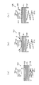
図1(a)乃至(d)は、紙幣収納庫を構成する各部品が紙幣導入ポジションにある状態を示す図、中間ポジション、ガイド片対移動中のポジション、紙幣堆積完了後のポジション(紙幣移載ポジション)を夫々示した正面図であり、図2(a)及び(b)は図1の各分図に対応した側面の状態を示す説明図である。
このような紙幣収納庫10を備えた紙幣処理装置1は、例えば各種自動販売機、入出金装置、両替機等の紙幣取扱装置に装備される。
紙幣処理装置1は、正逆転可能な搬送部材(ローラや搬送ベルト)を備えた紙幣導入・返却搬送路2と、紙幣導入・返却搬送路2から導入されてきた紙幣Pを積載する昇降自在、且つ弾性部材10aにより上向きに付勢された積載台10を備えた紙幣収納庫11と、を備えている。
紙幣収納庫11は、更に、積載台10の上方に昇降自在に支持され且つ積載台10上に積載された紙幣P1の幅方向両端線上面を押し下げつつ導入されてきた紙幣Pの幅方向両端縁下面を保持するガイド片対12と、ガイド片対12の上昇時にガイド片対により保持された紙幣Pの幅方向中間部を相対的に押し下げてガイド片対を越えて積載台上に移載する固定された紙幣ガイド13と、紙幣ガイド13により回転自在に支持されて紙幣返却方向へ回転駆動される繰出しローラ14と、を備えている。搬送部材3、ガイド片対12、及び繰出しローラ14を夫々駆動する各駆動源(モータ)20、21、22は、制御手段25により制御される。また、ガイド片対12の現在位置を検知するセンサを配置し、各センサからの検知信号に基づいて制御手段25がガイド片対の動作、停止タイミングを制御する。
ガイド片対(フォーク)12は、紙幣の幅方向両端縁を保持し得る間隔を隔てて平行に対向配置された2本のガイド片から成る。
Hereinafter, a bill storage (banknote processing device) according to the present invention will be described in detail with reference to an embodiment shown in the drawings.
FIGS. 1A to 1D are diagrams showing a state in which each component constituting the banknote storage is in the banknote introduction position, an intermediate position, a position where the guide piece pair is moving, and a position after banknote accumulation (banknote transfer). FIG. 2A and FIG. 2B are explanatory views showing the state of the side surface corresponding to each of the partial views of FIG. 1.
The banknote processing apparatus 1 provided with such a
The banknote handling apparatus 1 is freely movable up and down to load a banknote introduction / return transport path 2 provided with transportable members (rollers and transport belts) capable of rotating forward and backward, and a banknote P introduced from the banknote introduction / return transport path 2. And a banknote storage 11 provided with a loading table 10 urged upward by an
The banknote storage 11 is further supported so as to be movable up and down above the stacking table 10, and both edges in the width direction of the banknote P introduced while pressing down the upper surfaces of both ends in the width direction of the banknotes P1 stacked on the stacking table 10. The
The pair of guide pieces (forks) 12 is composed of two guide pieces arranged opposite to each other in parallel with an interval at which both edges of the bill in the width direction can be held.
本発明の特徴的な構成は、制御手段25が、各駆動源を制御してガイド片対12を所定のタイミングにて昇降させることにより、ガイド片対12を、紙幣ガイド13を下側に越えた紙幣導入ポジション(図1(a)、図2(a)実線で図示)と、紙幣ガイド13を上側に越えた紙幣移載ポジション(図1(d)、図2(a)鎖線で図示)と、紙幣導入ポジションと紙幣移載ポジションとの中間高さにある中間ポジション(図1(b)、図2(b))との3段階にて停止可能に構成した点にある。
更に、(b)の中間ポジションは、積載台10上面、或いは積載台上面の既堆積紙幣P1上面と繰出しローラ14との間でガイド片対12上の紙幣Pを挟圧保持可能となる位置にガイド片対12が留まるように設定してある。この中間ポジションで繰出しローラ14を返却方向へ回転させることによりガイド片対上の紙幣を紙幣導入・返却搬送路2へ返却することが可能である。
従来の紙幣処理装置に装備される紙幣収納庫では、ガイド片対12は図3(a)に示した最下降位置と、(c)に示した最上昇位置との二箇所でしか停止しないのに対して、本発明では、図1(b)に示した中間ポジションを含めた三箇所にて停止することにより、投入された紙幣Pを積載台上に移載するまでの間はガイド片対上に保持(積載台上の既堆積紙幣P1と物理的に隔離)しておくことが可能となる。このため、紙幣投入後に返却ボタン24が操作された場合にガイド片対上に保持された紙幣Pのみを返却することが可能となる。
The characteristic configuration of the present invention is that the control means 25 controls each drive source to raise and lower the
Further, the intermediate position of (b) is a position where the banknote P on the
In the banknote storage provided in the conventional banknote handling apparatus, the
本発明の構成及び動作を更に詳細に説明すると、図1(a)に示したガイド片対12が最下降位置にある紙幣導入ポジションでは、紙幣ガイド13との間に十分なスペースが確保されており、このスペースを利用して紙幣導入・返却搬送路2から導入されてきた一枚、又は複数枚の紙幣Pがガイド片対12上に載置される。
ここで利用者との取引がすべて終了すると、ガイド片対12上の紙幣Pを積載台10上に移載するために(b)(c)及び(d)に示すようにガイド片対12を順次上昇させる。
次に、図1(a)に示したように紙幣導入ポジションにあるガイド片対12上に紙幣が載置された状態で利用者が返却ボタン24をオンすると、制御手段25はガイド片対12を(b)に示した中間ポジションまで上昇させてから停止する。この状態では、ガイド片対12間の空間から繰出しローラ14が下方に突出しているため、弾性部材10aにより上向きに付勢された積載台10上の既堆積紙幣P1の上面との間で返却用紙幣Pの上面をニップすることができ、繰出しローラ14を返却方向へ回転させることにより返却用紙幣Pは紙幣導入・返却搬送路2へ返却される。紙幣導入・返却搬送路2を構成する搬送部材を返却方向へ回転させることにより紙幣を投入口から利用者に返却することができる。
紙幣を返却する過程でジャムが発生するなどして、紙幣処理装置が動作を停止した場合には、利用者が管理者を呼び出すこととなる。管理者は、装置内部を開放して復旧処理を行うが、利用者が投入した枚数分の紙幣はガイド片対12上か、或いは紙幣導入・返却搬送路2内に位置しているため、積載台11上の既堆積紙幣と混同する虞が皆無となる。つまり、利用者の申告を待たずに、投入された紙幣を特定し、現物を返却することが可能となる。
即ち、紙幣処理装置の稼働停止時に管理者が装置内部を開放した際に、ガイド片対12上、或いは紙幣導入・返却搬送路2上に残留した紙幣が利用者が投入した紙幣の現物であると目視で特定できるので、現物返却が可能となり、利用者との間のトラブルが解消される。
しかも、既存の紙幣収納庫、紙幣処理装置の制御手順を変更するだけで本発明の動作を得ることができるので、装置構成を大型化したり部品点数を増大させる必要がない点も大きなメリットである。
The configuration and operation of the present invention will be described in more detail. In the banknote introduction position where the
When all the transactions with the user are completed, the
Next, when the user turns on the return button 24 with the bill placed on the
When the banknote processing device stops operating due to a jam or the like in the process of returning the banknote, the user calls the manager. The administrator opens the inside of the apparatus and performs recovery processing. However, the banknotes for the number of sheets inserted by the user are located on the
That is, when the administrator opens the inside of the apparatus when the operation of the banknote processing apparatus is stopped, the banknote remaining on the
Moreover, since the operation of the present invention can be obtained simply by changing the control procedure of the existing banknote storage and banknote processing apparatus, it is also a great merit that it is not necessary to enlarge the apparatus configuration or increase the number of parts. .
1…紙幣処理装置、2…紙幣導入・返却搬送路、3…搬送部材、11…紙幣収納庫、10…積載台、10a…弾性部材、12…ガイド片対、13…紙幣ガイド、14…繰出しローラ、20、21、22…駆動源、25…制御手段 DESCRIPTION OF SYMBOLS 1 ... Banknote processing apparatus, 2 ... Banknote introduction and return conveyance path, 3 ... Conveyance member, 11 ... Banknote storage, 10 ... Loading stand, 10a ... Elastic member, 12 ... Guide piece pair, 13 ... Bill guide, 14 ... Feeding out Roller, 20, 21, 22 ... drive source, 25 ... control means
Claims (3)
前記ガイド片対は、前記紙幣ガイドを下側に越えた紙幣導入ポジションと、前記紙幣ガイドを上側に越えた紙幣移載ポジジョンと、前記紙幣導入ポジションと前記紙幣移載ポジジョンとの間の中間ポジジョンと、の3段階にて停止可能に構成されており、
導入された紙幣を返却する際に、導入された紙幣の幅方向両端縁下面を保持した状態のまま前記ガイド片対を前記紙幣導入ポジションから前記中間ポジションへと移動することにより、前記載置台上面或いは載置台上の既堆積紙幣上面と前記繰出しローラとの間で前記ガイド片対上の紙幣を狭圧保持し、この状態で前記繰出しローラを返却方向に回転することにより、前記ガイド片対上の紙幣を前記紙幣導入・返却搬送路へ返却可能としたことを特徴とする紙幣収納庫。 A loading table that can be moved up and down and urged upwards to load banknotes on the upper surface, and both edges in the width direction of the banknotes supported from above and below the loading table and introduced from the bill introduction / return conveyance path A pair of guide pieces for holding the lower surface, a banknote guide for lowering the middle part of the banknotes when the pair of guide pieces in the state of holding banknotes is raised, and transferring them onto the mounting table, and rotation by the banknote guides A bill storage provided with a feeding roller supported freely,
The pair of guide pieces includes a banknote introduction position that extends below the banknote guide, a banknote transfer position that extends above the banknote guide, and an intermediate position between the banknote introduction position and the banknote transfer position. And can be stopped in three stages,
When returning the introduced banknote, by moving the pair of guide pieces from the banknote introduction position to the intermediate position while holding the bottom surface of the both edges in the width direction of the introduced banknote, the upper surface of the mounting table described above Alternatively, by holding the banknote on the pair of guide pieces narrowly between the upper surface of the deposited banknotes on the mounting table and the feeding roller, and rotating the feeding roller in the returning direction in this state, A banknote storage, wherein the banknote can be returned to the banknote introduction / return conveyance path.
Priority Applications (1)
| Application Number | Priority Date | Filing Date | Title |
|---|---|---|---|
| JP2008181508A JP5130508B2 (en) | 2008-07-11 | 2008-07-11 | Banknote storage, banknote handling apparatus, and banknote handling apparatus |
Applications Claiming Priority (1)
| Application Number | Priority Date | Filing Date | Title |
|---|---|---|---|
| JP2008181508A JP5130508B2 (en) | 2008-07-11 | 2008-07-11 | Banknote storage, banknote handling apparatus, and banknote handling apparatus |
Publications (2)
| Publication Number | Publication Date |
|---|---|
| JP2010018404A true JP2010018404A (en) | 2010-01-28 |
| JP5130508B2 JP5130508B2 (en) | 2013-01-30 |
Family
ID=41703699
Family Applications (1)
| Application Number | Title | Priority Date | Filing Date |
|---|---|---|---|
| JP2008181508A Active JP5130508B2 (en) | 2008-07-11 | 2008-07-11 | Banknote storage, banknote handling apparatus, and banknote handling apparatus |
Country Status (1)
| Country | Link |
|---|---|
| JP (1) | JP5130508B2 (en) |
Cited By (2)
| Publication number | Priority date | Publication date | Assignee | Title |
|---|---|---|---|---|
| JP2013058072A (en) * | 2011-09-08 | 2013-03-28 | Toyo Networks & System Integration Co Ltd | Bill return device |
| CN108230576A (en) * | 2017-12-28 | 2018-06-29 | 南京怡化信息技术有限公司 | A kind of financial self-service equipment and its memory module |
Citations (2)
| Publication number | Priority date | Publication date | Assignee | Title |
|---|---|---|---|---|
| JPS61277528A (en) * | 1985-06-01 | 1986-12-08 | Matsushita Electric Ind Co Ltd | Bill delivery device |
| JP2001331841A (en) * | 2000-05-24 | 2001-11-30 | Hitachi Ltd | Device for handling paper sheets |
-
2008
- 2008-07-11 JP JP2008181508A patent/JP5130508B2/en active Active
Patent Citations (2)
| Publication number | Priority date | Publication date | Assignee | Title |
|---|---|---|---|---|
| JPS61277528A (en) * | 1985-06-01 | 1986-12-08 | Matsushita Electric Ind Co Ltd | Bill delivery device |
| JP2001331841A (en) * | 2000-05-24 | 2001-11-30 | Hitachi Ltd | Device for handling paper sheets |
Cited By (2)
| Publication number | Priority date | Publication date | Assignee | Title |
|---|---|---|---|---|
| JP2013058072A (en) * | 2011-09-08 | 2013-03-28 | Toyo Networks & System Integration Co Ltd | Bill return device |
| CN108230576A (en) * | 2017-12-28 | 2018-06-29 | 南京怡化信息技术有限公司 | A kind of financial self-service equipment and its memory module |
Also Published As
| Publication number | Publication date |
|---|---|
| JP5130508B2 (en) | 2013-01-30 |
Similar Documents
| Publication | Publication Date | Title |
|---|---|---|
| WO2005088566A1 (en) | Device for handling paper sheets or the like, automatic transaction device, and device for conveying paper sheets or the like | |
| JP2005259086A (en) | Paper sheet handling device | |
| JP5130508B2 (en) | Banknote storage, banknote handling apparatus, and banknote handling apparatus | |
| KR100893707B1 (en) | Method for detecting height of bundle of papers, and paper handling apparatus | |
| KR101591152B1 (en) | Paper sheet processing device | |
| JPH09267962A (en) | Paper sheet accumulating device and paper sheet processing device | |
| JP3172059B2 (en) | Paper binding machine | |
| JP4528081B2 (en) | Packaging coin delivery device | |
| JP4992002B2 (en) | Reflux-type banknote storage device and reflux-type banknote processing device | |
| JPS6181330A (en) | Paper sheets taking out device | |
| JP6028398B2 (en) | Medium separation apparatus and medium handling apparatus | |
| JP5791464B2 (en) | Banknote holding and separating mechanism and reflux-type banknote processing apparatus using the same | |
| JP5261815B2 (en) | Banknote handling apparatus and banknote handling apparatus | |
| KR100832050B1 (en) | Device for handling paper sheets or the like, automatic transaction device, and device for conveying paper sheets or the like | |
| JP2008269190A (en) | Paper money batch payment device | |
| JP2682822B2 (en) | Circular banknote processing method | |
| JP5101153B2 (en) | Banknote dispensing device | |
| JP3579097B2 (en) | Paper processing equipment | |
| KR20220068614A (en) | Bill deposit and withdrawal device | |
| KR20220068615A (en) | Operation method of bill deposit and withdrawal device | |
| JP6649140B2 (en) | Paper processing equipment | |
| JP2024012917A (en) | Paper sheet delivery device and paper sheet processing device | |
| JPS6347960Y2 (en) | ||
| JP4997458B2 (en) | Reflux-type banknote storage device and reflux-type banknote processing device | |
| JPS6262B2 (en) |
Legal Events
| Date | Code | Title | Description |
|---|---|---|---|
| A621 | Written request for application examination |
Free format text: JAPANESE INTERMEDIATE CODE: A621 Effective date: 20110427 |
|
| A521 | Request for written amendment filed |
Free format text: JAPANESE INTERMEDIATE CODE: A523 Effective date: 20110714 |
|
| A977 | Report on retrieval |
Free format text: JAPANESE INTERMEDIATE CODE: A971007 Effective date: 20120921 |
|
| TRDD | Decision of grant or rejection written | ||
| A01 | Written decision to grant a patent or to grant a registration (utility model) |
Free format text: JAPANESE INTERMEDIATE CODE: A01 Effective date: 20121002 |
|
| A01 | Written decision to grant a patent or to grant a registration (utility model) |
Free format text: JAPANESE INTERMEDIATE CODE: A01 |
|
| A61 | First payment of annual fees (during grant procedure) |
Free format text: JAPANESE INTERMEDIATE CODE: A61 Effective date: 20121010 |
|
| FPAY | Renewal fee payment (event date is renewal date of database) |
Free format text: PAYMENT UNTIL: 20151116 Year of fee payment: 3 |
|
| R150 | Certificate of patent or registration of utility model |
Free format text: JAPANESE INTERMEDIATE CODE: R150 Ref document number: 5130508 Country of ref document: JP Free format text: JAPANESE INTERMEDIATE CODE: R150 |
|
| S111 | Request for change of ownership or part of ownership |
Free format text: JAPANESE INTERMEDIATE CODE: R313111 |
|
| R350 | Written notification of registration of transfer |
Free format text: JAPANESE INTERMEDIATE CODE: R350 |
|
| S531 | Written request for registration of change of domicile |
Free format text: JAPANESE INTERMEDIATE CODE: R313531 |
|
| R350 | Written notification of registration of transfer |
Free format text: JAPANESE INTERMEDIATE CODE: R350 |
|
| R250 | Receipt of annual fees |
Free format text: JAPANESE INTERMEDIATE CODE: R250 |
|
| R250 | Receipt of annual fees |
Free format text: JAPANESE INTERMEDIATE CODE: R250 |
|
| R250 | Receipt of annual fees |
Free format text: JAPANESE INTERMEDIATE CODE: R250 |
|
| R250 | Receipt of annual fees |
Free format text: JAPANESE INTERMEDIATE CODE: R250 |
|
| R250 | Receipt of annual fees |
Free format text: JAPANESE INTERMEDIATE CODE: R250 |
|
| R250 | Receipt of annual fees |
Free format text: JAPANESE INTERMEDIATE CODE: R250 |
|
| R250 | Receipt of annual fees |
Free format text: JAPANESE INTERMEDIATE CODE: R250 |
|
| R250 | Receipt of annual fees |
Free format text: JAPANESE INTERMEDIATE CODE: R250 |
|
| R250 | Receipt of annual fees |
Free format text: JAPANESE INTERMEDIATE CODE: R250 |