JP2010015824A - 雷保護装置の絶縁電線側の放電部 - Google Patents
雷保護装置の絶縁電線側の放電部 Download PDFInfo
- Publication number
- JP2010015824A JP2010015824A JP2008174780A JP2008174780A JP2010015824A JP 2010015824 A JP2010015824 A JP 2010015824A JP 2008174780 A JP2008174780 A JP 2008174780A JP 2008174780 A JP2008174780 A JP 2008174780A JP 2010015824 A JP2010015824 A JP 2010015824A
- Authority
- JP
- Japan
- Prior art keywords
- insulated wire
- discharge
- discharge space
- discharge part
- protection device
- Prior art date
- Legal status (The legal status is an assumption and is not a legal conclusion. Google has not performed a legal analysis and makes no representation as to the accuracy of the status listed.)
- Granted
Links
- 238000009413 insulation Methods 0.000 title abstract description 21
- 239000011248 coating agent Substances 0.000 claims abstract description 24
- 238000000576 coating method Methods 0.000 claims abstract description 24
- 239000012212 insulator Substances 0.000 claims abstract description 22
- 238000010276 construction Methods 0.000 abstract description 10
- 150000001875 compounds Chemical class 0.000 description 11
- 238000005553 drilling Methods 0.000 description 9
- 230000015572 biosynthetic process Effects 0.000 description 2
- 238000007373 indentation Methods 0.000 description 2
- 238000000034 method Methods 0.000 description 2
- RYGMFSIKBFXOCR-UHFFFAOYSA-N Copper Chemical compound [Cu] RYGMFSIKBFXOCR-UHFFFAOYSA-N 0.000 description 1
- 229910052802 copper Inorganic materials 0.000 description 1
- 239000010949 copper Substances 0.000 description 1
- 238000009434 installation Methods 0.000 description 1
- 239000011810 insulating material Substances 0.000 description 1
- 239000002184 metal Substances 0.000 description 1
- 229910052751 metal Inorganic materials 0.000 description 1
- 229920003002 synthetic resin Polymers 0.000 description 1
- 239000000057 synthetic resin Substances 0.000 description 1
Images
Landscapes
- Thermistors And Varistors (AREA)
Abstract
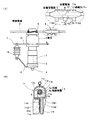
【解決手段】碍子2の接地部位に設けた限流素子側の放電部7に対して気中間隙を介して絶縁電線側に対向して設けた雷保護装置の絶縁電線側の放電部8において、大気から絶縁電線5の芯線5aに到達する放電空間路9を絶縁電線5の絶縁被覆5bに形成し、芯線5aのうち放電空間路9に面する部分が放電電極10になることを特徴とする雷保護装置の絶縁電線側の放電部。放電空間路9は穴である。
【選択図】 図1
Description
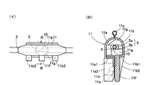
6バインド線、7限流素子側の放電部、8絶縁電線側の放電部、9放電空間路、
10放電電極、11絶縁カバー、11a左カバー、11a1底片、11a2連結片、
11b右カバー、11b1底片、11b2連結片、11c繋ぎ片、11d連結ピン、
11e連結孔、11f把持片、11g押さえ片、
12取付金物、13限流要素ユニット、14アークホーン
Claims (4)
- 碍子(2)の接地部位に設けた限流素子側の放電部(7)に対して気中間隙を介して絶縁電線側に対向して設けた雷保護装置の絶縁電線側の放電部(8)において、
大気から絶縁電線(5)の芯線(5a)に到達する放電空間路(9)を絶縁電線(5)の絶縁被覆(5b)に形成し、芯線(5a)のうち放電空間路(9)に面する部分が放電電極(10)になることを特徴とする雷保護装置の絶縁電線側の放電部。 - 放電空間路(9)は穴であることを特徴とする請求項1記載の雷保護装置の絶縁電線側の放電部。
- 放電空間路(9)は、絶縁被覆(5b)の円周方向に沿って連続する円弧状またはリング状であることを特徴とする請求項1記載の雷保護装置の絶縁電線側の放電部。
- 放電空間路(9)を覆う絶縁カバー(11)を、絶縁電線(5)の全周を囲んで固定してあることを特徴とする請求項2又は3記載の雷保護装置の絶縁電線側の放電部。
Priority Applications (1)
| Application Number | Priority Date | Filing Date | Title |
|---|---|---|---|
| JP2008174780A JP5100537B2 (ja) | 2008-07-03 | 2008-07-03 | 雷保護装置の絶縁電線側の放電部 |
Applications Claiming Priority (1)
| Application Number | Priority Date | Filing Date | Title |
|---|---|---|---|
| JP2008174780A JP5100537B2 (ja) | 2008-07-03 | 2008-07-03 | 雷保護装置の絶縁電線側の放電部 |
Publications (2)
| Publication Number | Publication Date |
|---|---|
| JP2010015824A true JP2010015824A (ja) | 2010-01-21 |
| JP5100537B2 JP5100537B2 (ja) | 2012-12-19 |
Family
ID=41701754
Family Applications (1)
| Application Number | Title | Priority Date | Filing Date |
|---|---|---|---|
| JP2008174780A Expired - Fee Related JP5100537B2 (ja) | 2008-07-03 | 2008-07-03 | 雷保護装置の絶縁電線側の放電部 |
Country Status (1)
| Country | Link |
|---|---|
| JP (1) | JP5100537B2 (ja) |
Citations (2)
| Publication number | Priority date | Publication date | Assignee | Title |
|---|---|---|---|---|
| JPS5632687A (en) * | 1979-08-27 | 1981-04-02 | Masao Tomita | Method of sealing arc extinguishing powder for continuous breakdown type flash display unit |
| JPS62192517U (ja) * | 1986-05-29 | 1987-12-07 |
-
2008
- 2008-07-03 JP JP2008174780A patent/JP5100537B2/ja not_active Expired - Fee Related
Patent Citations (2)
| Publication number | Priority date | Publication date | Assignee | Title |
|---|---|---|---|---|
| JPS5632687A (en) * | 1979-08-27 | 1981-04-02 | Masao Tomita | Method of sealing arc extinguishing powder for continuous breakdown type flash display unit |
| JPS62192517U (ja) * | 1986-05-29 | 1987-12-07 |
Also Published As
| Publication number | Publication date |
|---|---|
| JP5100537B2 (ja) | 2012-12-19 |
Similar Documents
| Publication | Publication Date | Title |
|---|---|---|
| CN105514882B (zh) | 一种电缆剥皮钳及其剥皮方法 | |
| JP5100537B2 (ja) | 雷保護装置の絶縁電線側の放電部 | |
| CN105633863B (zh) | 一种电缆剥皮钳及其剥皮方法 | |
| JP2015019497A (ja) | 接地短絡器具 | |
| KR102788799B1 (ko) | 외부 환경적 요인으로부터 전력선을 보호하는 바인드리스 라인 포스트 커버 | |
| JP5349509B2 (ja) | 縁線接続方法 | |
| CN104992798A (zh) | 低压带电装接绝缘护套 | |
| JP2017054651A (ja) | 避雷器縁線抜け防止具 | |
| JP4716888B2 (ja) | 接地棒及びその作成方法 | |
| JP2007026802A (ja) | アース線付き電線 | |
| CN210326753U (zh) | 一种高压电缆局部剥切的固定装置 | |
| CN219990815U (zh) | 一种接地线绕线装置 | |
| CN205599826U (zh) | 用于钳断屏顶带电小母线的断线钳 | |
| JP5642586B2 (ja) | 避雷器 | |
| CN204464077U (zh) | 绝缘操作杆及装置 | |
| CN104466699A (zh) | 配电设备 | |
| CN211265031U (zh) | 一种便于开剥的电缆和光缆 | |
| JP5628373B2 (ja) | 高圧カットアウト用耐塩支持碍子の保護カバー | |
| JP6488779B2 (ja) | 引下線用端末キャップ | |
| JP2023105010A (ja) | コンクリート製ポール | |
| CN205722944U (zh) | 方便安装的临时布线线缆结构 | |
| JP2006066218A (ja) | アース線付平型ケーブル | |
| CN205406162U (zh) | 一种船用火灾报警控制电缆 | |
| CN204517390U (zh) | 四合一防雷保护器 | |
| JP5955892B2 (ja) | ケーブル挿通口保護カバー |
Legal Events
| Date | Code | Title | Description |
|---|---|---|---|
| A621 | Written request for application examination |
Free format text: JAPANESE INTERMEDIATE CODE: A621 Effective date: 20110331 |
|
| A977 | Report on retrieval |
Free format text: JAPANESE INTERMEDIATE CODE: A971007 Effective date: 20120907 |
|
| TRDD | Decision of grant or rejection written | ||
| A01 | Written decision to grant a patent or to grant a registration (utility model) |
Free format text: JAPANESE INTERMEDIATE CODE: A01 Effective date: 20120919 |
|
| A01 | Written decision to grant a patent or to grant a registration (utility model) |
Free format text: JAPANESE INTERMEDIATE CODE: A01 |
|
| A61 | First payment of annual fees (during grant procedure) |
Free format text: JAPANESE INTERMEDIATE CODE: A61 Effective date: 20120925 |
|
| FPAY | Renewal fee payment (event date is renewal date of database) |
Free format text: PAYMENT UNTIL: 20151005 Year of fee payment: 3 |
|
| R150 | Certificate of patent or registration of utility model |
Free format text: JAPANESE INTERMEDIATE CODE: R150 |
|
| R250 | Receipt of annual fees |
Free format text: JAPANESE INTERMEDIATE CODE: R250 |
|
| R250 | Receipt of annual fees |
Free format text: JAPANESE INTERMEDIATE CODE: R250 |
|
| R250 | Receipt of annual fees |
Free format text: JAPANESE INTERMEDIATE CODE: R250 |
|
| LAPS | Cancellation because of no payment of annual fees |