JP2010014101A - Multiple vane pump - Google Patents

Multiple vane pump Download PDF

Info

Publication number
JP2010014101A
JP2010014101A JP2008194538A JP2008194538A JP2010014101A JP 2010014101 A JP2010014101 A JP 2010014101A JP 2008194538 A JP2008194538 A JP 2008194538A JP 2008194538 A JP2008194538 A JP 2008194538A JP 2010014101 A JP2010014101 A JP 2010014101A
Authority
JP
Japan
Prior art keywords
vane pump
pump
vane
switching valve
hydraulic
Prior art date
Legal status (The legal status is an assumption and is not a legal conclusion. Google has not performed a legal analysis and makes no representation as to the accuracy of the status listed.)
Pending
Application number
JP2008194538A
Other languages
Japanese (ja)
Inventor
Tsunefumi Arita
恒文 有田
Tomoyuki Fujita
朋之 藤田
Masamichi Sugihara
雅道 杉原
Hiroshi Shiozaki
浩 塩崎
Koichiro Akatsuka
浩一朗 赤塚
Current Assignee (The listed assignees may be inaccurate. Google has not performed a legal analysis and makes no representation or warranty as to the accuracy of the list.)
KYB Corp
Original Assignee
Kayaba Industry Co Ltd
Priority date (The priority date is an assumption and is not a legal conclusion. Google has not performed a legal analysis and makes no representation as to the accuracy of the date listed.)
Filing date
Publication date
Application filed by Kayaba Industry Co Ltd filed Critical Kayaba Industry Co Ltd
Priority to JP2008194538A priority Critical patent/JP2010014101A/en
Publication of JP2010014101A publication Critical patent/JP2010014101A/en
Pending legal-status Critical Current

Links

Images

Abstract

<P>PROBLEM TO BE SOLVED: To provide a multiple vane pump superior in pump efficiency. <P>SOLUTION: This multiple vane pump has a switching valve 26 connected by at least one vane pump among a plurality of vane pumps 101 and 102, and switching the supply of a working fluid delivered by the vane pumps 101 and 102 to a hydraulic apparatus 21 or the return of the fluid to a suction passage 8 by connecting the plurality of vane pumps 101 and 102 having a rotor 2 connected to a driving shaft 1, a plurality of vanes 3 arranged in the radial direction to the rotor 2 and a cam ring 4 for storing the rotor 2 so as to be reciprocative, and sliding a tip of the vane 3 on a cam surface 4a of the inner periphery according to the rotation of the rotor 2 in parallel by connecting the respective rotors 2 to a common driving shaft 1. The switching valve 26 performs switching operation by an output of an external driving means having ab output associated with a pump delivery flow rate. <P>COPYRIGHT: (C)2010,JPO&INPIT

Description

本発明は、油圧機器の油圧供給源として用いられ、複数のベーンポンプが並列に接続された多連式ベーンポンプに関するものである。   The present invention relates to a multiple vane pump that is used as a hydraulic pressure supply source for hydraulic equipment and in which a plurality of vane pumps are connected in parallel.

従来のベーンポンプとして、駆動軸に連結されたロータがカムリングに回転自在に収容され、ロータとカムリングとの間に画成されたポンプ室の拡縮によって作動油を給排するものが知られている。   As a conventional vane pump, a rotor connected to a drive shaft is rotatably accommodated in a cam ring, and hydraulic oil is supplied and discharged by expansion and contraction of a pump chamber defined between the rotor and the cam ring.

特許文献1には、第1ポンプと第2ポンプを備える二連式のベーンポンプにおいて、第2ポンプの吐出流量が所定値以上になると第1ポンプの吐出油をポンプ吸込通路へと逃がすアンロードバルブを備えるものが開示されている。
特開昭58−93973号公報
Patent Document 1 discloses an unload valve for releasing oil discharged from a first pump into a pump suction passage when a discharge flow rate of the second pump exceeds a predetermined value in a dual vane pump including a first pump and a second pump. What is provided is disclosed.
JP 58-93973 A

特許文献1に記載のアンロードバルブは、内部に設けられたオリフィスを第2ポンプの吐出油が通過する際の前後差圧によって作動するものであるため、アンロードバルブの作動にあたって圧力損失が大きくなる。これにより、ポンプの負荷が大きくなり、ポンプ効率が悪くなる。   Since the unload valve described in Patent Document 1 is operated by a differential pressure before and after the discharge oil of the second pump passes through an orifice provided inside, the pressure loss is large when the unload valve is operated. Become. As a result, the load on the pump increases and the pump efficiency deteriorates.

本発明は、上記の問題点に鑑みてなされたものであり、ポンプ効率の良好な多連式ベーンポンプを提供することを目的とする。   The present invention has been made in view of the above problems, and an object of the present invention is to provide a multiple vane pump with good pump efficiency.

本発明は、駆動軸に連結されたロータと、前記ロータに対して径方向に往復動可能に設けられた複数のベーンと、前記ロータを収容すると共に、前記ロータの回転に伴って内周のカム面に前記ベーンの先端部が摺動するカムリングと、前記ロータ、前記カムリング、及び隣り合う前記ベーンによって画成されたポンプ室と、を備える複数のベーンポンプが、それぞれの前記ロータが共通の前記駆動軸にて連結されることによって並列に接続された多連式ベーンポンプにおいて、前記複数のベーンポンプのうちの少なくともいずれか一つのベーンポンプに接続され、当該ベーンポンプが吐出する作動流体を油圧機器に供給するか又は吸込通路へと戻すかを切り換える切換弁を備え、前記切換弁は、外部駆動手段によって作動することを特徴とする。   The present invention includes a rotor coupled to a drive shaft, a plurality of vanes provided so as to be capable of reciprocating in the radial direction with respect to the rotor, and housing the rotor. A plurality of vane pumps including a cam ring in which a tip of the vane slides on a cam surface, and a pump chamber defined by the rotor, the cam ring, and the adjacent vane, and each of the rotors share the same In a multiple vane pump connected in parallel by being connected by a drive shaft, the working fluid connected to at least one of the plurality of vane pumps is supplied to hydraulic equipment. Or a switching valve for switching back to the suction passage, and the switching valve is actuated by an external driving means. .

本発明によれば、ベーンポンプが吐出する作動流体を油圧機器に対して供給するか又は吸込通路へと戻すかを切り換える切換弁は外部駆動手段によって作動するため、切換弁の作動にあたって圧力損失が大きくなることがなく、ポンプ効率は良好となる。   According to the present invention, since the switching valve for switching whether the working fluid discharged from the vane pump is supplied to the hydraulic equipment or returned to the suction passage is operated by the external driving means, the pressure loss is large when the switching valve is operated. The pump efficiency is good.

以下、図面を参照して、本発明の実施の形態について説明する。   Embodiments of the present invention will be described below with reference to the drawings.

本発明の多連式ベーンポンプは、車両に搭載される油圧機器、例えば、パワーステアリング装置や変速機等の油圧供給源として用いられ、複数のベーンポンプが並列に接続されたものである。本実施の形態では、ベーンポンプが2つ並列に接続された二連式ベーンポンプについて説明する。   The multiple vane pump of the present invention is used as a hydraulic pressure supply source for a hydraulic device mounted on a vehicle, for example, a power steering device or a transmission, and a plurality of vane pumps are connected in parallel. In the present embodiment, a dual vane pump in which two vane pumps are connected in parallel will be described.

(第1の実施の形態)
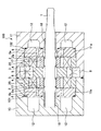
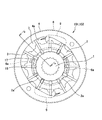
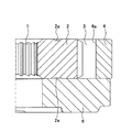
図1及び図2を参照して、本発明の第1の実施の形態に係る二連式ベーンポンプ100について説明する。図1は二連式ベーンポンプ100における駆動軸に平行な断面を示す断面図であり、図2は二連式ベーンポンプ100のポンプカートリッジの平面図である。
(First embodiment)
A double vane pump 100 according to a first embodiment of the present invention will be described with reference to FIGS. FIG. 1 is a cross-sectional view showing a cross section parallel to the drive shaft in the double vane pump 100, and FIG. 2 is a plan view of a pump cartridge of the double vane pump 100.

二連式ベーンポンプ100は、エンジン31(図3参照)の動力が伝達される共通の駆動軸1に第1ベーンポンプ101及び第2ベーンポンプ102のそれぞれのロータ2が連結され、駆動軸1の回転によって互いのロータ2が回転するものである。   In the double vane pump 100, the rotor 2 of each of the first vane pump 101 and the second vane pump 102 is connected to a common drive shaft 1 to which the power of the engine 31 (see FIG. 3) is transmitted. The mutual rotors 2 rotate.

第1ベーンポンプ101及び第2ベーンポンプ102は、ロータ2に対して径方向に往復動可能に設けられた複数のベーン3と、ロータ2を収容すると共にロータ2の回転に伴って内周のカム面4aにベーン3の先端部が摺動するカムリング4とを備える。   The first vane pump 101 and the second vane pump 102 include a plurality of vanes 3 provided so as to be capable of reciprocating in the radial direction with respect to the rotor 2, and the inner cam surface that accommodates the rotor 2 and rotates as the rotor 2 rotates. 4a includes a cam ring 4 on which the tip of the vane 3 slides.

ロータ2には、外周面に開口部を有するスリット16が所定間隔をおいて放射状に形成され、ベーン3は、スリット16に摺動自在に挿入される。   In the rotor 2, slits 16 having openings on the outer peripheral surface are radially formed at predetermined intervals, and the vanes 3 are slidably inserted into the slits 16.

スリット16の基端側には、ポンプの吐出圧が導かれる背圧室17が画成される。隣り合う背圧室17は、ロータ2に形成された円弧状の溝2aによって連通し、この溝2aにはポンプ吐出圧が常時導かれている。ベーン3は、背圧室17の圧力によってスリット16から抜け出る方向に押圧され、先端部がカムリング4の内周のカム面4aに当接する。これにより、カムリング4の内部には、ロータ2の外面、カムリングのカム面4a、及び隣り合うベーン3によって複数のポンプ室7が画成される。ロータ2、ベーン3、及びカムリング4によってポンプカートリッジ20が構成される。   A back pressure chamber 17 into which the discharge pressure of the pump is guided is defined on the proximal end side of the slit 16. Adjacent back pressure chambers 17 communicate with each other by an arc-shaped groove 2a formed in the rotor 2, and pump discharge pressure is always guided to the groove 2a. The vane 3 is pressed in the direction of coming out of the slit 16 by the pressure of the back pressure chamber 17, and the tip part comes into contact with the inner cam surface 4 a of the cam ring 4. As a result, a plurality of pump chambers 7 are defined in the cam ring 4 by the outer surface of the rotor 2, the cam surface 4 a of the cam ring, and the adjacent vanes 3. The rotor 2, the vane 3, and the cam ring 4 constitute a pump cartridge 20.

カムリング4は、内周のカム面4aが楕円形状をした環状の部材であり、ロータ2の回転に伴ってカム面4aを摺動する各ベーン3間によって仕切られるポンプ室7の容積を拡張する吸込領域と、ポンプ室7の容積を収縮する吐出領域とを有する。このように、各ポンプ室7は、ロータ2の回転に伴って拡縮する。本実施の形態では、カムリング4は、2つの吸込領域と2つの吐出領域とを有する。   The cam ring 4 is an annular member having an inner circumferential cam surface 4 a having an elliptical shape, and expands the volume of the pump chamber 7 partitioned by the vanes 3 that slide on the cam surface 4 a as the rotor 2 rotates. It has a suction region and a discharge region that contracts the volume of the pump chamber 7. Thus, each pump chamber 7 expands and contracts as the rotor 2 rotates. In the present embodiment, the cam ring 4 has two suction areas and two discharge areas.

第1ベーンポンプ101及び第2ベーンポンプ102のポンプカートリッジ20の間にはセンタープレート5が配置されると共に、それぞれのポンプカートリッジ20の側部にはサイドプレート6が配置される。このように、ポンプカートリッジ20は、センタープレート5とサイドプレート6との間に挟持され、ポンプ室7は、センタープレート5とサイドプレート6とによって密閉される。   A center plate 5 is disposed between the pump cartridges 20 of the first vane pump 101 and the second vane pump 102, and a side plate 6 is disposed on the side of each pump cartridge 20. Thus, the pump cartridge 20 is sandwiched between the center plate 5 and the side plate 6, and the pump chamber 7 is sealed by the center plate 5 and the side plate 6.

センタープレート5には、カムリング4の吸込領域に向けて開口し、ポンプ室7に作動油(作動流体)を導く吸込通路8が形成される。   The center plate 5 is formed with a suction passage 8 that opens toward the suction region of the cam ring 4 and guides hydraulic oil (working fluid) to the pump chamber 7.

サイドプレート6には、カムリング4の吐出領域に向けて開口し、ポンプ室7が吐出する作動油が導かれる円弧状の2つの吐出ポート9(図2参照)が形成される。   The side plate 6 is formed with two arc-shaped discharge ports 9 (see FIG. 2) that open toward the discharge region of the cam ring 4 and guide the hydraulic oil discharged from the pump chamber 7.

各ポンプ室7は、ロータ2の回転に伴って、カムリング4の吸込領域にて吸込通路8を通じて作動油を吸込み、カムリング4の吐出領域にて吐出ポート9を通じて作動油を吐出する。このように、各ポンプ室7は、ロータ2の回転に伴う拡縮によって作動油を給排する。   Each pump chamber 7 sucks the working oil through the suction passage 8 in the suction region of the cam ring 4 as the rotor 2 rotates, and discharges the working oil through the discharge port 9 in the discharge region of the cam ring 4. Thus, each pump chamber 7 supplies and discharges hydraulic oil by expansion and contraction accompanying the rotation of the rotor 2.

なお、二連式ベーンポンプ100は、単式のベーンポンプと比較して、ポンプカートリッジ20の幅が小さい。このため、単式のベーンポンプでは、吸い込み性能改善のため、ポンプカートリッジの両側から作動油を吸い込むのが一般的であるが、二連式ベーンポンプ100では、ポンプカートリッジ20の一方側のみから作動油を吸い込む構造で吸込性能が十分確保される。   The double vane pump 100 is smaller in the width of the pump cartridge 20 than the single vane pump. For this reason, in a single vane pump, hydraulic oil is generally sucked from both sides of the pump cartridge in order to improve the suction performance, but in the dual vane pump 100, hydraulic oil is sucked from only one side of the pump cartridge 20. The structure ensures sufficient suction performance.

駆動軸1は、ブッシュ18を介して第1ポンプボディ10及び第2ポンプボディ11に回転自在に支持される。第1ポンプボディ10に形成されたポンプ収容凹部10a内には、第1ベーンポンプ101のサイドプレート6とポンプカートリッジ20が積層して収容され、第2ポンプボディ11に形成されたポンプ収容凹部11a内には、第2ベーンポンプ102のサイドプレート6とポンプカートリッジ20と共にセンタープレート5が積層して収容される。このように、第1ポンプボディ10には第1ベーンポンプ101が収容され、第2ポンプボディ11には第2ベーンポンプ102が収容される。   The drive shaft 1 is rotatably supported by the first pump body 10 and the second pump body 11 via the bush 18. The side plate 6 of the first vane pump 101 and the pump cartridge 20 are stacked and housed in the pump housing recess 10 a formed in the first pump body 10, and inside the pump housing recess 11 a formed in the second pump body 11. The center plate 5 is stacked and accommodated together with the side plate 6 and the pump cartridge 20 of the second vane pump 102. Thus, the first pump body 10 accommodates the first vane pump 101 and the second pump body 11 accommodates the second vane pump 102.

第1ポンプボディ10と第2ポンプボディ11は、互いの開口部を有する面を当接して一体に締結され、それぞれのポンプ収容凹部10a,11aが封止される。   The first pump body 10 and the second pump body 11 are fastened together by abutting the surfaces having the openings, and the respective pump housing recesses 10a and 11a are sealed.

第1ベーンポンプ101及び第2ベーンポンプ102のカムリング4及びサイドプレート6は、センタープレート5を挿通する位置決めピン(図示省略)によって回り止めされる。位置決めピンによって、カムリング4に対するセンタープレート5とサイドプレート6の相対回転が規制され、カムリング4の吸込領域と吸込通路8との位置決め、及びカムリング4の吐出領域と吐出ポート9との位置決めが行われる。   The cam ring 4 and the side plate 6 of the first vane pump 101 and the second vane pump 102 are prevented from rotating by positioning pins (not shown) that pass through the center plate 5. The relative rotation of the center plate 5 and the side plate 6 with respect to the cam ring 4 is restricted by the positioning pin, positioning of the suction area of the cam ring 4 and the suction passage 8 and positioning of the discharge area of the cam ring 4 and the discharge port 9 are performed. .

第1ポンプボディ10及び第2ポンプボディ11には、吐出ポート9に連通し吐出ポート9から吐出された作動油が流入する高圧室12と、高圧室12に連通し高圧室12の作動油を外部の油圧機器21(図3参照)へと供給する吐出通路13(図3参照)とが形成される。   The first pump body 10 and the second pump body 11 are connected to the discharge port 9 and the high pressure chamber 12 into which the hydraulic oil discharged from the discharge port 9 flows, and the high pressure chamber 12 is connected to the high pressure chamber 12. A discharge passage 13 (see FIG. 3) for supplying to an external hydraulic device 21 (see FIG. 3) is formed.

また、高圧室12の作動油は、サイドプレート6に形成された貫通孔6aを通じてロータ2の円弧状の溝2aに導かれて各背圧室17へと導かれる。   The hydraulic oil in the high-pressure chamber 12 is guided to the arc-shaped groove 2 a of the rotor 2 through the through-hole 6 a formed in the side plate 6 and is guided to each back pressure chamber 17.

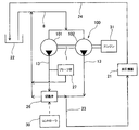
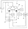
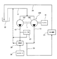
次に、図3を参照して、二連式ベーンポンプ100の油圧回路について説明する。図3は二連式ベーンポンプ100の油圧回路図である。   Next, the hydraulic circuit of the double vane pump 100 will be described with reference to FIG. FIG. 3 is a hydraulic circuit diagram of the double vane pump 100.

第1ベーンポンプ101及び第2ベーンポンプ102は、吸込通路8を通じてタンク22から作動油を吸い込み、それぞれの吐出通路13へと吐出する。吐出された作動油は、合流通路23にて合流し、油圧機器21へと供給される。   The first vane pump 101 and the second vane pump 102 suck the hydraulic oil from the tank 22 through the suction passage 8 and discharge it to the discharge passages 13. The discharged hydraulic oil joins in the joining passage 23 and is supplied to the hydraulic device 21.

油圧機器21に供給された作動油は、油圧機器21を駆動するためのアクチュエータへと供給された後、戻り通路24を通じてタンク22へと排出される。   The hydraulic oil supplied to the hydraulic device 21 is supplied to an actuator for driving the hydraulic device 21 and then discharged to the tank 22 through the return passage 24.

第1ベーンポンプ101の吐出通路13には、第1ベーンポンプ101が吐出する作動油を油圧機器21に供給するか又は吸込通路8へと戻すかを切り換える切換弁26が介装される。つまり、第1ベーンポンプ101から吐出される作動油は、切換弁26の切り換えによって合流通路23又は吸込通路8のいずれかに選択的に導かれる。   A switching valve 26 is provided in the discharge passage 13 of the first vane pump 101 for switching whether the hydraulic oil discharged from the first vane pump 101 is supplied to the hydraulic equipment 21 or returned to the suction passage 8. That is, the hydraulic oil discharged from the first vane pump 101 is selectively guided to either the merging passage 23 or the suction passage 8 by switching the switching valve 26.

切換弁26は、コントローラ30から出力される制御電流によって作動が制御される電磁式切換弁である。具体的には、コントローラ30は、入力されるエンジン回転数に応じて切換弁26を切り換える。ロータ2は駆動軸1を介してエンジン31と直接連結されている。したがって、切換弁26は、ロータ2の回転数であるポンプ回転数に応じて切り換えられることになる。   The switching valve 26 is an electromagnetic switching valve whose operation is controlled by a control current output from the controller 30. Specifically, the controller 30 switches the switching valve 26 according to the input engine speed. The rotor 2 is directly connected to the engine 31 via the drive shaft 1. Therefore, the switching valve 26 is switched according to the pump rotation speed that is the rotation speed of the rotor 2.

図3及び図4を参照して、二連式ベーンポンプ100の動作について説明する。図4は、二連式ベーンポンプ100の流量特性を示すグラフ図であり、ポンプ回転数Nに対する二連式ベーンポンプ100から油圧機器21に供給されるポンプ吐出流量Qを示すグラフ図である。   The operation of the double vane pump 100 will be described with reference to FIGS. FIG. 4 is a graph showing the flow rate characteristics of the double vane pump 100, and is a graph showing the pump discharge flow rate Q supplied from the double vane pump 100 to the hydraulic device 21 with respect to the pump rotational speed N.

二連式ベーンポンプ100の始動時には、切換弁26は、作動油を合流通路23に導くポジションに設定される。これにより、油圧機器21には、第1ベーンポンプ101と第2ベーンポンプ102の合計吐出流量が供給される。   When the double vane pump 100 is started, the switching valve 26 is set to a position for guiding the hydraulic oil to the merging passage 23. Thereby, the total discharge flow rate of the first vane pump 101 and the second vane pump 102 is supplied to the hydraulic device 21.

二連式ベーンポンプ100の吐出流量は、ポンプ回転数の上昇に伴って増加し、油圧機器21を駆動するための必要流量を超えて増加する。   The discharge flow rate of the double vane pump 100 increases as the pump rotational speed increases, and exceeds the flow rate required for driving the hydraulic device 21.

第2ベーンポンプ102単体の吐出流量が必要流量以上となるポンプ回転数N1にて、切換弁26は、作動油を吸込通路8へと戻すポジションに切り換えられ、第1ベーンポンプ101から吐出された作動油は、吸込通路8へと戻される。これにより、油圧機器21には、第2ベーンポンプ102単体の吐出流量が供給される。このとき、第2ベーンポンプ102の吐出流量は必要流量以上であるため、図4に示すように、切換弁26の切り換え後も油圧機器21に供給される作動油は、必要流量が確保される。なお、図4では、第1ベーンポンプ101と第2ベーンポンプ102の基本吐出容量が同じである場合の流量特性である。   At the pump rotation speed N1 at which the discharge flow rate of the second vane pump 102 alone becomes equal to or higher than the required flow rate, the switching valve 26 is switched to a position for returning the hydraulic oil to the suction passage 8 and the hydraulic oil discharged from the first vane pump 101 Is returned to the suction passage 8. Thus, the discharge flow rate of the second vane pump 102 alone is supplied to the hydraulic device 21. At this time, since the discharge flow rate of the second vane pump 102 is equal to or higher than the required flow rate, the required flow rate is ensured for the hydraulic oil supplied to the hydraulic device 21 even after the switching valve 26 is switched as shown in FIG. FIG. 4 shows the flow rate characteristics when the basic discharge capacities of the first vane pump 101 and the second vane pump 102 are the same.

コントローラ30には、第2ベーンポンプ102単体の吐出流量が必要流量以上となるポンプ回転数N1が予め記憶されており、エンジン回転数がN1以上となると、コントローラ30から切換弁26に対して切り換えのための制御電流が出力される。このように、コントローラ30から切換弁26に出力される制御電流は、ポンプ吐出流量に関連して出力される。   The controller 30 stores in advance a pump rotational speed N1 at which the discharge flow rate of the second vane pump 102 alone is greater than or equal to the required flow rate. When the engine rotational speed exceeds N1, the controller 30 switches the switching valve 26 to the switching valve 26. Control current is output. As described above, the control current output from the controller 30 to the switching valve 26 is output in association with the pump discharge flow rate.

第1ベーンポンプ101の吐出通路13における切換弁26の上流側には、切換弁26の切り換え時に第1ベーンポンプ101の吐出圧が所定の圧力に達したときに、その吐出圧を逃がすリリーフ弁27が介装される。   On the upstream side of the switching valve 26 in the discharge passage 13 of the first vane pump 101, there is a relief valve 27 that releases the discharge pressure when the discharge pressure of the first vane pump 101 reaches a predetermined pressure when the switching valve 26 is switched. Intervened.

切換弁26は、作動油を合流通路23に導くポジションから吸込通路8へと戻すポジションに切り換えられる際、第2ベーンポンプ102から吐出される作動油が切換弁26を通じて吸込通路8へと導かれることを防止するため、一旦全閉となってから切り換えられる。そのため、切換弁26の全閉時、第1ベーンポンプ101の吐出通路13は、閉じ込められた状態となり圧力が上昇する。この圧力が所定の圧力に達したときにリリーフ弁27は開弁動作し、吐出通路13の圧力を逃がす。リリーフ弁27を通過した作動油は、吸込通路8へと導かれる。なお、リリーフ弁27を通過した作動油を第2ベーンポンプ102の吐出通路13へと導くようにしてもよい。   When the switching valve 26 is switched from the position for guiding the hydraulic oil to the merge passage 23 to the position for returning the hydraulic oil to the suction passage 8, the hydraulic oil discharged from the second vane pump 102 is guided to the suction passage 8 through the switching valve 26. In order to prevent this, it is switched after being fully closed once. Therefore, when the switching valve 26 is fully closed, the discharge passage 13 of the first vane pump 101 becomes confined and the pressure increases. When this pressure reaches a predetermined pressure, the relief valve 27 opens to release the pressure in the discharge passage 13. The hydraulic oil that has passed through the relief valve 27 is guided to the suction passage 8. The hydraulic oil that has passed through the relief valve 27 may be guided to the discharge passage 13 of the second vane pump 102.

以上のように、二連式ベーンポンプ100は、ポンプ始動時には第1ベーンポンプ101と第2ベーンポンプ102の合計吐出流量によって、また、ポンプ回転数の上昇後は、第2ベーンポンプ102単体の吐出流量によって必要流量を確保するものであり、効率の良い運転が行われる。   As described above, the double vane pump 100 is required by the total discharge flow rate of the first vane pump 101 and the second vane pump 102 at the start of the pump, and after the pump rotation speed is increased by the discharge flow rate of the second vane pump 102 alone. The flow rate is ensured and efficient operation is performed.

また、切換弁26は、コントローラ30から出力される制御電流、つまり外部駆動手段によって作動するものであり、弁内部に設けられたオリフィスを作動油が通過する際の前後差圧によって作動するものでないため、切換弁26の作動にあたって圧力損失が大きくなることがなく、切換弁26の切り換えに伴い第1ベーンポンプ101の負荷が増加することがない。したがって、第1ベーンポンプ101のポンプ効率は、オリフィスを有する切換弁を用いる場合と比較して、非常に良好となる。   Further, the switching valve 26 is operated by a control current output from the controller 30, that is, an external driving means, and is not operated by a differential pressure before and after hydraulic fluid passes through an orifice provided inside the valve. Therefore, the pressure loss does not increase when the switching valve 26 is operated, and the load on the first vane pump 101 does not increase as the switching valve 26 is switched. Therefore, the pump efficiency of the first vane pump 101 is very good as compared with the case where a switching valve having an orifice is used.

なお、3つ以上のベーンポンプが並列に接続される多連式ベーンポンプの場合には、切換弁26は、複数のベーンポンプのうちの少なくともいずれか一つのベーンポンプに接続される。   In the case of a multiple vane pump in which three or more vane pumps are connected in parallel, the switching valve 26 is connected to at least one of the plurality of vane pumps.

また、以上では、切換弁26が作動油を吸込通路8へと戻すポジションに切り換えられた場合、第1ベーンポンプ101から吐出された作動油は、吸込通路8へと戻されると説明した。具体的には、第1ベーンポンプ101から吐出され切換弁26によって吸込通路8へと戻される作動油は、図5に示すように、切換弁26の切り換え後に作動油を油圧機器21に供給する第2ベーンポンプ102の吸込通路8へと戻すことが望ましい。これにより、第2ベーンポンプ102の吸込性能が向上する。   In the above description, it has been described that the hydraulic oil discharged from the first vane pump 101 is returned to the suction passage 8 when the switching valve 26 is switched to the position for returning the hydraulic oil to the suction passage 8. Specifically, the hydraulic fluid discharged from the first vane pump 101 and returned to the suction passage 8 by the switching valve 26 is supplied to the hydraulic equipment 21 after the switching valve 26 is switched, as shown in FIG. It is desirable to return to the suction passage 8 of the two-vane pump 102. Thereby, the suction performance of the 2nd vane pump 102 improves.

次に、図6を参照して、切換弁26の作動を切り換える外部駆動手段の他の構成について説明する。図6は二連式ベーンポンプ100の油圧回路図である。   Next, with reference to FIG. 6, another configuration of the external driving means for switching the operation of the switching valve 26 will be described. FIG. 6 is a hydraulic circuit diagram of the double vane pump 100.

切換弁26は、油圧機器21から供給されるパイロット油圧によって作動が制御されるパイロット式切換弁である。具体的には、コントローラ30には、第2ベーンポンプ102単体の吐出流量が必要流量以上となるポンプ回転数N1(図4参照)が予め記憶されており、エンジン回転数がN1以上となると、コントローラ30から油圧機器21に対して指令信号が出力される。コントローラ30から指令信号を受けた油圧機器21は、切換弁26に対して切り換えのためのパイロット油圧を供給する。このように、油圧機器21から切換弁26に供給されるパイロット油圧は、ポンプ吐出流量に関連して供給(出力)される。   The switching valve 26 is a pilot-type switching valve whose operation is controlled by a pilot hydraulic pressure supplied from the hydraulic device 21. Specifically, the controller 30 stores in advance a pump rotation speed N1 (see FIG. 4) at which the discharge flow rate of the second vane pump 102 alone is greater than or equal to the required flow rate. When the engine rotation speed is N1 or more, the controller 30 A command signal is output from 30 to the hydraulic device 21. The hydraulic device 21 that has received the command signal from the controller 30 supplies a pilot hydraulic pressure for switching to the switching valve 26. Thus, the pilot hydraulic pressure supplied from the hydraulic device 21 to the switching valve 26 is supplied (output) in relation to the pump discharge flow rate.

以上のように、切換弁26は、エンジン回転数に応じて供給されるパイロット油圧、つまり外部駆動手段によって切り換えられるため、切換弁26の切り換えに伴い第1ベーンポンプ101の負荷が増加することがなく、ポンプ効率は非常に良好となる。   As described above, since the switching valve 26 is switched by the pilot hydraulic pressure that is supplied according to the engine speed, that is, by the external driving means, the load on the first vane pump 101 does not increase with the switching of the switching valve 26. The pump efficiency will be very good.

(第2の実施の形態)
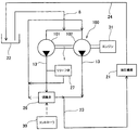
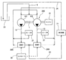
図7及び図8を参照して、本発明の第2の実施の形態に係る二連式ベーンポンプ200について説明する。図7は二連式ベーンポンプ200の油圧回路図であり、図8は二連式ベーンポンプ200の流量特性を示すグラフ図である。以下では、上記第1の実施の形態と相違する点を中心に説明する。
(Second Embodiment)
With reference to FIG.7 and FIG.8, the double-type vane pump 200 which concerns on the 2nd Embodiment of this invention is demonstrated. FIG. 7 is a hydraulic circuit diagram of the dual vane pump 200, and FIG. 8 is a graph showing the flow rate characteristics of the dual vane pump 200. Below, it demonstrates centering on the point which is different from the said 1st Embodiment.

二連式ベーンポンプ200では、第1ベーンポンプ101及び第2ベーンポンプ102の吐出通路13の双方に、ポンプが吐出する作動油を油圧機器21に対して供給するか又は吸込通路8へと戻すかを切り換える切換弁26が介装される。以下では、第1ベーンポンプ101に接続される切換弁26を「切換弁26A」、第2ベーンポンプ102に接続される切換弁26を「切換弁26B」と称する。   In the double vane pump 200, switching is made between whether the hydraulic oil discharged from the pump is supplied to the hydraulic equipment 21 or returned to the suction passage 8 to both the discharge passages 13 of the first vane pump 101 and the second vane pump 102. A switching valve 26 is interposed. Hereinafter, the switching valve 26 connected to the first vane pump 101 is referred to as “switching valve 26A”, and the switching valve 26 connected to the second vane pump 102 is referred to as “switching valve 26B”.

また、第1ベーンポンプ101及び第2ベーンポンプ102の吐出通路13の双方に、リリーフ弁27が介装される。   A relief valve 27 is interposed in both the discharge passages 13 of the first vane pump 101 and the second vane pump 102.

さらに、二連式ベーンポンプ200では、第1ベーンポンプ101と第2ベーンポンプ102の基本吐出容量が異なる。具体的には、第1ベーンポンプ101の基本吐出容量が第2ベーンポンプ102の基本吐出容量よりも大きい。各ベーンポンプの基本吐出容量は、カムリング4の形状によって変化するポンプ室7の容量によって設定される。   Further, in the dual vane pump 200, the basic discharge capacities of the first vane pump 101 and the second vane pump 102 are different. Specifically, the basic discharge capacity of the first vane pump 101 is larger than the basic discharge capacity of the second vane pump 102. The basic discharge capacity of each vane pump is set by the capacity of the pump chamber 7 that varies depending on the shape of the cam ring 4.

次に、二連式ベーンポンプ200の動作について説明する。   Next, the operation of the double vane pump 200 will be described.

二連式ベーンポンプ200の始動時には、切換弁26A及び切換弁26Bは、作動油を合流通路23に導くポジションに設定される。これにより、油圧機器21には、第1ベーンポンプ101と第2ベーンポンプ102の合計吐出流量が供給される。   At the time of starting the double vane pump 200, the switching valve 26 </ b> A and the switching valve 26 </ b> B are set to positions where the hydraulic oil is guided to the merging passage 23. Thereby, the total discharge flow rate of the first vane pump 101 and the second vane pump 102 is supplied to the hydraulic device 21.

二連式ベーンポンプ200の吐出流量は、ポンプ回転数の上昇に伴って増加し、油圧機器21を駆動するための必要流量を超えて増加する。   The discharge flow rate of the double vane pump 200 increases as the pump rotation speed increases, and increases beyond the required flow rate for driving the hydraulic device 21.

第1ベーンポンプ101単体の吐出流量が必要流量以上となるポンプ回転数N1にて、切換弁26Bは、作動油を吸込通路8へと戻すポジションに切り換えられ、第2ベーンポンプ102から吐出された作動油は、吸込通路8へと戻される。これにより、油圧機器21には、第1ベーンポンプ101単体の吐出流量が供給される。このとき、第1ベーンポンプ101の吐出流量は必要流量以上であるため、図8に示すように、切換弁26Bの切り換え後も油圧機器21に供給される作動油は、必要流量が確保される。なお、図8及び以下の説明において、切換弁26A,26Bが作動油を油圧機器21に導く場合を「ON」、作動油を吸込通路8へと戻す場合を「OFF」と称する。   At the pump rotational speed N1 at which the discharge flow rate of the first vane pump 101 alone is equal to or higher than the required flow rate, the switching valve 26B is switched to a position for returning the hydraulic oil to the suction passage 8 and is discharged from the second vane pump 102. Is returned to the suction passage 8. As a result, the discharge flow rate of the first vane pump 101 alone is supplied to the hydraulic device 21. At this time, since the discharge flow rate of the first vane pump 101 is equal to or higher than the required flow rate, the required flow rate is ensured for the hydraulic oil supplied to the hydraulic device 21 even after the switching valve 26B is switched as shown in FIG. In FIG. 8 and the following description, the case where the switching valves 26A and 26B guide the hydraulic oil to the hydraulic equipment 21 is referred to as “ON”, and the case where the hydraulic oil is returned to the suction passage 8 is referred to as “OFF”.

さらにポンプ回転数が上昇し、第2ベーンポンプ102単体の吐出流量が必要流量以上となるポンプ回転数N2にて、切換弁26Bは作動油を合流通路23に導くポジションに切り換えられると共に、切換弁26Aは作動油を吸込通路8へと戻すポジションに切り換えられる。これにより、第2ベーンポンプ102から吐出された作動油は油圧機器21に供給され、第1ベーンポンプ101から吐出された作動油は、吸込通路8へと戻される。このとき、第2ベーンポンプ102の吐出流量は必要流量以上であるため、図8に示すように、切換弁26A,26Bの切り換え後も油圧機器21に供給される作動油は、必要流量が確保される。   Further, at the pump rotational speed N2 at which the pump rotational speed rises and the discharge flow rate of the second vane pump 102 alone becomes equal to or higher than the required flow rate, the switching valve 26B is switched to a position for guiding the hydraulic oil to the merging passage 23 and the switching valve 26A. Is switched to a position for returning the hydraulic oil to the suction passage 8. Thereby, the hydraulic oil discharged from the second vane pump 102 is supplied to the hydraulic device 21, and the hydraulic oil discharged from the first vane pump 101 is returned to the suction passage 8. At this time, since the discharge flow rate of the second vane pump 102 is equal to or higher than the required flow rate, the required flow rate is ensured for the hydraulic oil supplied to the hydraulic device 21 even after the switching valves 26A and 26B are switched as shown in FIG. The

このように、二連式ベーンポンプ200は、ポンプ始動時からポンプ回転数がN1未満までは、第1ベーンポンプ101及び第2ベーンポンプ102の2台にて油圧機器21に作動油を供給し、ポンプ回転数がN1以上N2未満では、大容量の第1ベーンポンプ101単体にて油圧機器21に作動油を供給し、ポンプ回転数がN2以上では、小容量の第2ベーンポンプ102単体にて油圧機器21に作動油を供給する。このように、二連式ベーンポンプ200は、ポンプの運転パターンを3つ有し、3段階の切り換えが可能である。   As described above, the double vane pump 200 supplies hydraulic oil to the hydraulic equipment 21 by the two units of the first vane pump 101 and the second vane pump 102 until the pump rotation speed is less than N1 from the start of the pump to rotate the pump. When the number is N1 or more and less than N2, hydraulic oil is supplied to the hydraulic device 21 with a single large-capacity first vane pump 101, and when the pump speed is N2 or more, the hydraulic device 21 is supplied with a small-capacity second vane pump 102 alone. Supply hydraulic oil. Thus, the double vane pump 200 has three operation patterns of the pump and can be switched in three stages.

上記第1の実施の形態の二連式ベーンポンプ100では、第1ベーンポンプ101にしか切換弁26が接続されていないため、図8に点線にて示すように、切換弁26を切り換えるまで(ポンプ回転数N2)に、ポンプ吐出流量が必要流量を大きくオーバーしてしまう。   In the double vane pump 100 according to the first embodiment, the switching valve 26 is connected only to the first vane pump 101. Therefore, as shown by the dotted line in FIG. The pump discharge flow rate greatly exceeds the required flow rate in several N2).

これに対して、二連式ベーンポンプ200では、3段階の切り換えが可能であるため、ポンプ吐出流量が必要流量をオーバーする量が小さく、ポンプの駆動ロスが小さい。また、小容量の第2ベーンポンプ102の切換弁26Bは、ポンプ回転数N1にてOFFとし、吐出流量が必要流量以上となるポンプ回転数N2にてONとなるように制御されるため、ポンプ吐出流量が必要流量をオーバーする量を小さくすることができる。   On the other hand, the dual vane pump 200 can be switched in three stages, so that the amount by which the pump discharge flow rate exceeds the required flow rate is small, and the drive loss of the pump is small. Further, the switching valve 26B of the small capacity second vane pump 102 is controlled to be turned off at the pump rotational speed N1 and to be turned on at the pump rotational speed N2 at which the discharge flow rate is equal to or higher than the necessary flow rate. The amount by which the flow rate exceeds the required flow rate can be reduced.

なお、3つ以上のベーンポンプが並列に接続される多連式ベーンポンプの場合には、切換弁26は、複数のベーンポンプのそれぞれに接続される。例えば、三連式ベーンポンプの場合には、ポンプの運転パターンを7つ有し、7段階の切り換えが可能となる。   In the case of a multiple vane pump in which three or more vane pumps are connected in parallel, the switching valve 26 is connected to each of the plurality of vane pumps. For example, in the case of a triple vane pump, there are seven pump operation patterns, and seven stages of switching are possible.

また、上記第1の実施の形態と同様に、切換弁26によって吸込通路8へと戻される作動油は、図9に示すように、切換弁26の切り換え後に作動油を油圧機器21に供給するベーンポンプの吸込通路8へと戻すことが望ましい。これにより、ベーンポンプ101,102の吸込性能が向上する。   Similarly to the first embodiment, the hydraulic oil returned to the suction passage 8 by the switching valve 26 supplies the hydraulic oil to the hydraulic equipment 21 after the switching valve 26 is switched, as shown in FIG. It is desirable to return to the suction passage 8 of the vane pump. Thereby, the suction performance of the vane pumps 101 and 102 is improved.

(第3の実施の形態)
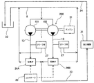
図10を参照して、本発明の第3の実施の形態に係る二連式ベーンポンプ300について説明する。図10は二連式ベーンポンプ300の油圧回路図である。以下では、上記第1及び第2の実施の形態との相違点について説明する。
(Third embodiment)
With reference to FIG. 10, a double vane pump 300 according to a third embodiment of the present invention will be described. FIG. 10 is a hydraulic circuit diagram of the double vane pump 300. Hereinafter, differences from the first and second embodiments will be described.

二連式ベーンポンプ300は、油圧機器21から排出される作動油を吸込通路8へと導く還流通路28と、還流通路28に介装されたオリフィス29とをさらに備える。   The double vane pump 300 further includes a reflux passage 28 that guides the hydraulic oil discharged from the hydraulic device 21 to the suction passage 8, and an orifice 29 interposed in the reflux passage 28.

オリフィス29は、作動油がオリフィス29を通過した直後に、吸込通路8へと合流するように、還流通路28の下流側に介装される。   The orifice 29 is interposed on the downstream side of the reflux passage 28 so that the hydraulic oil merges with the suction passage 8 immediately after passing through the orifice 29.

油圧機器21には、二連式ベーンポンプ300から供給された作動油を、油圧機器21を駆動するためのアクチュエータと還流通路28とに分配する分配弁(図示省略)が設けられる。   The hydraulic device 21 is provided with a distribution valve (not shown) that distributes the hydraulic oil supplied from the double vane pump 300 to an actuator for driving the hydraulic device 21 and the return passage 28.

還流通路28にはオリフィス29が介装されるため、油圧機器21の分配弁によって還流通路28へと導かれてオリフィス29を通過した作動油の流速は大きくなる。オリフィス29を通過した直後の流速が大きい作動油は吸込通路8に導かれるため、タンク22から吸込通路8を通じて作動油を吸い込む二連式ベーンポンプ300の吸込性能が向上し、キャビテーションの発生が防止される。   Since the return passage 28 is provided with an orifice 29, the flow rate of the hydraulic oil that is guided to the return passage 28 by the distribution valve of the hydraulic device 21 and passes through the orifice 29 increases. Since the hydraulic oil having a high flow rate immediately after passing through the orifice 29 is guided to the suction passage 8, the suction performance of the double vane pump 300 that sucks the hydraulic oil from the tank 22 through the suction passage 8 is improved, and the occurrence of cavitation is prevented. The

なお、油圧機器21から排出され吸込通路8へと導かれる作動油は、図11に示すように、第1ベーンポンプ101及び第2ベーンポンプ102のうち基本吐出容量が大きい側の第1ベーンポンプ101の吸込通路8へと導くのが望ましい。これにより、基本吐出容量が大きく吸込性能が悪い第1ベーンポンプ101の吸込性能を改善することができる。   As shown in FIG. 11, the hydraulic oil discharged from the hydraulic device 21 and guided to the suction passage 8 is sucked into the first vane pump 101 having the larger basic discharge capacity among the first vane pump 101 and the second vane pump 102. It is desirable to lead to the passage 8. Thereby, the suction performance of the 1st vane pump 101 with a large basic discharge capacity and bad suction performance can be improved.

また、第1ベーンポンプ101から吐出され切換弁26によって吸込通路8へと戻される作動油は、図12及び図13に示すように、還流流路28におけるオリフィス29の上流側へと導くのが望ましい。これにより、オリフィス29を通過する作動油の流量が多くなり、オリフィス29を通過した作動油の流速はさらに大きくなる。これにより、二連式ベーンポンプ300の吸込性能はさらに向上する。例えば、作動油中に空気が多く含有される場合においても、キャビテーションの発生を防止することができる。   Further, it is desirable that the hydraulic oil discharged from the first vane pump 101 and returned to the suction passage 8 by the switching valve 26 is guided to the upstream side of the orifice 29 in the reflux passage 28 as shown in FIGS. . As a result, the flow rate of the hydraulic oil passing through the orifice 29 is increased, and the flow rate of the hydraulic oil passing through the orifice 29 is further increased. Thereby, the suction performance of the double vane pump 300 is further improved. For example, even when a large amount of air is contained in the hydraulic oil, cavitation can be prevented from occurring.

(第4の実施の形態)
図2及び図14を参照して、本発明の第4の実施の形態について説明する。図14は図2におけるa−a断面を示す断面図である。以下では、上記第1及び第2の実施の形態との相違点について説明する。
(Fourth embodiment)
A fourth embodiment of the present invention will be described with reference to FIGS. FIG. 14 is a cross-sectional view showing an aa cross section in FIG. Hereinafter, differences from the first and second embodiments will be described.

第1ベーンポンプ101及び第2ベーンポンプ102のうちの一方のロータ2に形成された溝2aは、他方のロータ2に形成された溝2aと比較して断面積が大きく形成される。具体的には、一方の溝2aは、他方の溝2aと比較してロータ2の軸方向の深さ(図9における紙面上下方向)が深く形成される。   The groove 2 a formed in one rotor 2 of the first vane pump 101 and the second vane pump 102 has a larger cross-sectional area than the groove 2 a formed in the other rotor 2. Specifically, one groove 2a is formed deeper in the axial depth of the rotor 2 (the vertical direction in FIG. 9) than the other groove 2a.

本実施の形態によれば、溝2aの断面積が大きく形成されたベーンポンプでは、背圧室17の作動油が溝2aを通じて他の背圧室17に逃げやすいため、ベーン3が背圧室17に進入する際の抵抗が減り、ベーン3の先端部とカムリング4のカム面4aとの摺動抵抗が減少する。これにより、ポンプの駆動トルクが低減し、ポンプ効率が向上する。   According to the present embodiment, in the vane pump in which the groove 2a has a large cross-sectional area, the hydraulic oil in the back pressure chamber 17 easily escapes to the other back pressure chamber 17 through the groove 2a. The resistance at the time of entering is reduced, and the sliding resistance between the tip of the vane 3 and the cam surface 4a of the cam ring 4 is reduced. Thereby, the driving torque of the pump is reduced and the pump efficiency is improved.

また、ポンプ始動時においては、切換弁26(26A,26B)はONであり、第1ベーンポンプ101と第2ベーンポンプ102の吐出側は連通した状態である。このため、溝2aの断面積が大きく形成された一方のベーンポンプの背圧室17には、他方のベーンポンプの吐出圧が作用するため、一方のベーンポンプは問題なく始動することができる。このように、ポンプの駆動トルクを低減しつつ、ポンプ始動性は確保される。   At the time of starting the pump, the switching valve 26 (26A, 26B) is ON, and the discharge sides of the first vane pump 101 and the second vane pump 102 are in communication. For this reason, since the discharge pressure of the other vane pump acts on the back pressure chamber 17 of one vane pump in which the cross-sectional area of the groove 2a is formed large, one vane pump can be started without any problem. In this way, the pump startability is ensured while reducing the pump drive torque.

(第5の実施の形態)
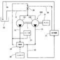
図15を参照して、本発明の第5の実施の形態に係る二連式ベーンポンプ500について説明する。図15は二連式ベーンポンプ500の油圧回路図である。以下では、上記第1の実施の形態との相違点について説明する。
(Fifth embodiment)
A double vane pump 500 according to a fifth embodiment of the present invention will be described with reference to FIG. FIG. 15 is a hydraulic circuit diagram of the double vane pump 500. Hereinafter, differences from the first embodiment will be described.

二連式ベーンポンプ500は、ポンプ始動時において、作動油の温度が所定温度以下である場合には、切換弁26は作動油を吸込通路8へと戻すポジションに切り換えられる。   In the double vane pump 500, when the temperature of the hydraulic oil is equal to or lower than a predetermined temperature when the pump is started, the switching valve 26 is switched to a position for returning the hydraulic oil to the suction passage 8.

これにより、タンク22から二連式ベーンポンプ500への吸込流量が減少し、吸込負荷が減少するため、キャビテーションの発生が防止される。   As a result, the suction flow rate from the tank 22 to the double vane pump 500 is reduced and the suction load is reduced, thereby preventing the occurrence of cavitation.

本発明は上記の実施の形態に限定されずに、その技術的な思想の範囲内において種々の変更がなしうることは明白である。   The present invention is not limited to the above-described embodiment, and it is obvious that various modifications can be made within the scope of the technical idea.

例えば、合流通路23を廃止し、第1ベーンポンプ101及び第2ベーンポンプ102の吐出通路13を、それぞれ油圧機器21に接続するようにしてもよい。その場合、切換弁26を油圧機器21内に設けるようにしてもよい。   For example, the merging passage 23 may be eliminated, and the discharge passages 13 of the first vane pump 101 and the second vane pump 102 may be connected to the hydraulic equipment 21 respectively. In that case, the switching valve 26 may be provided in the hydraulic device 21.

また、上記実施の形態では、切換弁26は吐出通路13に設けるようにしたが、2つの吐出ポート9のうちの一方のポートに切換弁26を設けるようにしてもよい。   In the above embodiment, the switching valve 26 is provided in the discharge passage 13, but the switching valve 26 may be provided in one of the two discharge ports 9.

本発明に係るベーンポンプは、車両用のパワーステアリング装置や変速機等の油圧供給源に適用することができる。   The vane pump according to the present invention can be applied to a hydraulic power supply source such as a power steering device or a transmission for a vehicle.

本発明の第1の実施の形態に係る二連式ベーンポンプにおける駆動軸に平行な断面を示す断面図である。It is sectional drawing which shows a cross section parallel to the drive shaft in the double vane pump which concerns on the 1st Embodiment of this invention. 本発明の第1の実施の形態に係る二連式ベーンポンプのポンプカートリッジの平面図である。1 is a plan view of a pump cartridge of a double vane pump according to a first embodiment of the present invention. 本発明の第1の実施の形態に係る二連式ベーンポンプの油圧回路図である。1 is a hydraulic circuit diagram of a double vane pump according to a first embodiment of the present invention. 本発明の第1の実施の形態に係る二連式ベーンポンプの流量特性を示すグラフ図である。It is a graph which shows the flow volume characteristic of the double vane pump which concerns on the 1st Embodiment of this invention. 本発明の第1の実施の形態に係る二連式ベーンポンプの他の形態を示す油圧回路図である。It is a hydraulic circuit diagram which shows the other form of the double vane pump which concerns on the 1st Embodiment of this invention. 本発明の第1の実施の形態に係る二連式ベーンポンプの油圧回路の他の形態である。It is another form of the hydraulic circuit of the double vane pump which concerns on the 1st Embodiment of this invention. 本発明の第2の実施の形態に係る二連式ベーンポンプの油圧回路図である。FIG. 5 is a hydraulic circuit diagram of a dual vane pump according to a second embodiment of the present invention. 本発明の第2の実施の形態に係る二連式ベーンポンプの流量特性を示すグラフ図である。It is a graph which shows the flow volume characteristic of the double vane pump which concerns on the 2nd Embodiment of this invention. 本発明の第2の実施の形態に係る二連式ベーンポンプの他の形態を示す油圧回路図である。It is a hydraulic circuit diagram which shows the other form of the double vane pump which concerns on the 2nd Embodiment of this invention. 本発明の第3の実施の形態に係る二連式ベーンポンプの油圧回路図である。FIG. 5 is a hydraulic circuit diagram of a dual vane pump according to a third embodiment of the present invention. 本発明の第3の実施の形態に係る二連式ベーンポンプの他の形態を示す油圧回路図である。It is a hydraulic circuit diagram which shows the other form of the double vane pump which concerns on the 3rd Embodiment of this invention. 本発明の第3の実施の形態に係る二連式ベーンポンプの他の形態を示す油圧回路図である。It is a hydraulic circuit diagram which shows the other form of the double vane pump which concerns on the 3rd Embodiment of this invention. 本発明の第3の実施の形態に係る二連式ベーンポンプの他の形態を示す油圧回路図である。It is a hydraulic circuit diagram which shows the other form of the double vane pump which concerns on the 3rd Embodiment of this invention. 図2におけるa−a断面を示す断面図である。It is sectional drawing which shows the aa cross section in FIG. 本発明の第5の実施の形態に係る二連式ベーンポンプの油圧回路図である。FIG. 10 is a hydraulic circuit diagram of a dual vane pump according to a fifth embodiment of the present invention.

符号の説明Explanation of symbols

100,200,300,500 二連式ベーンポンプ
101,102 ベーンポンプ
1 駆動軸
2 ロータ
2a 溝
3 ベーン
4 カムリング
5 センタープレート
6 サイドプレート
7 ポンプ室
8 吸込通路
9 吐出ポート
10,11 ポンプボディ
13 吐出通路
17 背圧室
20 ポンプカートリッジ
21 油圧機器
23 合流通路
26,26A,26B 切換弁
27 リリーフ弁
28 還流通路
29 オリフィス
30 コントローラ
100, 200, 300, 500 Double vane pump 101, 102 Vane pump 1 Drive shaft 2 Rotor 2a Groove 3 Vane 4 Cam ring 5 Center plate 6 Side plate 7 Pump chamber 8 Suction passage 9 Discharge port 10, 11 Pump body 13 Discharge passage 17 Back pressure chamber 20 Pump cartridge 21 Hydraulic equipment 23 Junction passage 26, 26A, 26B Switching valve 27 Relief valve 28 Recirculation passage 29 Orifice 30 Controller

Claims (13)

駆動軸に連結されたロータと、
前記ロータに対して径方向に往復動可能に設けられた複数のベーンと、
前記ロータを収容すると共に、前記ロータの回転に伴って内周のカム面に前記ベーンの先端部が摺動するカムリングと、
を備える複数のベーンポンプが、それぞれの前記ロータが共通の前記駆動軸にて連結されることによって並列に接続された多連式ベーンポンプにおいて、
前記複数のベーンポンプのうちの少なくともいずれか一つのベーンポンプに接続され、当該ベーンポンプが吐出する作動流体を油圧機器に供給するか又は吸込通路へと戻すかを切り換える切換弁を備え、
前記切換弁は、ポンプ吐出流量に関連した出力をもつ外部駆動手段の出力によって切換作動することを特徴とする多連式ベーンポンプ。
A rotor coupled to the drive shaft;
A plurality of vanes provided so as to be capable of reciprocating in the radial direction with respect to the rotor;
A cam ring that houses the rotor, and the tip of the vane slides on the cam surface of the inner periphery as the rotor rotates.
A plurality of vane pumps, wherein the rotors are connected in parallel by being connected by the common drive shaft,
A switching valve that is connected to at least one of the plurality of vane pumps and that switches whether the working fluid discharged from the vane pump is supplied to the hydraulic device or returned to the suction passage;
The multiple valve vane pump, wherein the switching valve is switched by an output of an external driving means having an output related to a pump discharge flow rate.
前記切換弁は、前記駆動軸に回転力を伝達するエンジンの回転数に応じて出力される制御電流によって切換作動する電磁式切換弁であることを特徴とする請求項1に記載の多連式ベーンポンプ。   2. The multiple switching valve according to claim 1, wherein the switching valve is an electromagnetic switching valve that is switched by a control current that is output in accordance with an engine speed that transmits a rotational force to the drive shaft. Vane pump. 前記切換弁は、前記駆動軸に回転力を伝達するエンジンの回転数に応じて供給されるパイロット液圧によって切換作動するパイロット式切換弁であることを特徴とする請求項1に記載の多連式ベーンポンプ。   2. The multiple switching valve according to claim 1, wherein the switching valve is a pilot-type switching valve that is switched by a pilot hydraulic pressure that is supplied in accordance with the rotational speed of an engine that transmits a rotational force to the drive shaft. Vane pump. 前記切換弁は、前記複数のベーンポンプのそれぞれに接続されることを特徴とする請求項1から請求項3のいずれか一つに記載の多連式ベーンポンプ。   The multiple vane pump according to any one of claims 1 to 3, wherein the switching valve is connected to each of the plurality of vane pumps. 前記複数のベーンポンプの基本吐出容量が互いに異なることを特徴とする請求項4に記載の多連式ベーンポンプ。   The multiple vane pump according to claim 4, wherein basic discharge capacities of the plurality of vane pumps are different from each other. 前記切換弁によって前記吸込通路へと戻される作動流体は、前記複数のベーンポンプのうち作動流体を油圧機器に供給しているベーンポンプの吸込通路へと戻されることを特徴とする請求項1から請求項5のいずれか一つに記載の多連式ベーンポンプ。   The working fluid returned to the suction passage by the switching valve is returned to the suction passage of the vane pump that supplies the working fluid to the hydraulic equipment among the plurality of vane pumps. The multiple vane pump according to any one of 5. 前記ベーンポンプが2つ並列に接続され、
ポンプ始動時には、大容量ベーンポンプ及び小容量ベーンポンプに接続された前記切換弁は、作動流体を前記油圧機器に供給するポジションに設定され、
ポンプ回転数の上昇に伴い、前記大容量ベーンポンプの吐出流量が前記油圧機器を駆動するための必要流量以上となった場合に、前記小容量ベーンポンプに接続された前記切換弁は、作動流体を前記吸込通路へと戻すポジションに切り換えられ、
ポンプ回転数がさらに上昇し、前記小容量ベーンポンプの吐出流量が前記必要流量以上となった場合に、前記小容量ベーンポンプに接続された前記切換弁は、作動流体を前記油圧機器に供給するポジションに切り換えられると共に、前記大容量ベーンポンプに接続された前記切換弁は、作動流体を前記吸込通路へと戻すポジションに切り換えられることを特徴とする請求項5に記載の多連式ベーンポンプ。
Two vane pumps connected in parallel;
At the time of starting the pump, the switching valve connected to the large-capacity vane pump and the small-capacity vane pump is set to a position for supplying the hydraulic fluid to the hydraulic equipment,
When the discharge flow rate of the large-capacity vane pump becomes greater than the required flow rate for driving the hydraulic equipment as the pump speed increases, the switching valve connected to the small-capacity vane pump supplies the working fluid to the hydraulic fluid. Switched to the position to return to the suction passage,
When the pump rotational speed further increases and the discharge flow rate of the small capacity vane pump exceeds the required flow rate, the switching valve connected to the small capacity vane pump is in a position to supply the working fluid to the hydraulic equipment. 6. The multiple vane pump according to claim 5, wherein the switching valve connected to the large-capacity vane pump is switched to a position for returning the working fluid to the suction passage.
前記切換弁の上流側には、前記切換弁の切り換え時に前記ベーンポンプの吐出圧が所定の圧力に達したときに、当該吐出圧を逃がすリリーフ弁が介装されることを特徴とする請求項1から請求項7のいずれか一つに記載の多連式ベーンポンプ。   2. A relief valve is provided upstream of the switching valve to release the discharge pressure when the discharge pressure of the vane pump reaches a predetermined pressure when the switching valve is switched. The multiple vane pump according to claim 7. 前記油圧機器から排出される作動流体を前記吸込通路へと導く還流通路と、
前記還流通路に介装されたオリフィスと、
をさらに備えることを特徴とする請求項1から請求項8のいずれか一つに記載の多連式ベーンポンプ。
A recirculation passage for guiding the working fluid discharged from the hydraulic equipment to the suction passage;
An orifice interposed in the reflux passage;
The multiple vane pump according to any one of claims 1 to 8, further comprising:
前記油圧機器から排出され前記吸込通路へと導かれる作動流体は、前記複数のベーンポンプのうち基本吐出容量が大きいベーンポンプの吸込通路へと導かれることを特徴とする請求項9に記載の多連式ベーンポンプ。   The multiple fluid system according to claim 9, wherein the working fluid discharged from the hydraulic device and guided to the suction passage is guided to a suction passage of a vane pump having a large basic discharge capacity among the plurality of vane pumps. Vane pump. 前記切換弁によって前記吸込通路へと戻される作動流体は、前記還流流路における前記オリフィスの上流側へと導かれることを特徴とする請求項9又は請求項10に記載の多連式ベーンポンプ。   11. The multi-type vane pump according to claim 9, wherein the working fluid returned to the suction passage by the switching valve is guided to an upstream side of the orifice in the return flow path. 前記ベーンポンプが2つ並列に接続され、
前記ロータは、
前記ベーンが摺動自在に挿入されるスリットと、
前記スリットの基端側に画成され、前記ベーンを前記スリットから抜け出る方向に押圧する背圧室と、
隣り合う前記背圧室を連通し、ポンプ吐出圧が常時導かれる円弧状の溝と、を備え、
前記2つのベーンポンプのうちの一方のベーンポンプの前記溝は、他方のベーンポンプと比較して断面積が大きいことを特徴とする請求項1から請求項11のいずれか一つに記載の多連式ベーンポンプ。
Two vane pumps connected in parallel;
The rotor is
A slit into which the vane is slidably inserted;
A back pressure chamber defined on the base end side of the slit and pressing the vane in the direction of exiting the slit;
An arc-shaped groove through which the back pressure chambers adjacent to each other are communicated and the pump discharge pressure is always guided;
The multiple vane pump according to any one of claims 1 to 11, wherein the groove of one of the two vane pumps has a cross-sectional area larger than that of the other vane pump. .
ポンプ始動時において、作動流体の温度が所定温度以下である場合には、前記切換弁は作動流体を前記吸込通路へと戻すポジションに切り換えられることを特徴とする請求項1から請求項3のいずれか一つに記載の多連式ベーンポンプ。   4. The pump according to claim 1, wherein when the temperature of the working fluid is equal to or lower than a predetermined temperature when the pump is started, the switching valve is switched to a position for returning the working fluid to the suction passage. A multiple-type vane pump according to any one of the above.
JP2008194538A 2008-06-05 2008-07-29 Multiple vane pump Pending JP2010014101A (en)

Priority Applications (1)

Application Number Priority Date Filing Date Title
JP2008194538A JP2010014101A (en) 2008-06-05 2008-07-29 Multiple vane pump

Applications Claiming Priority (2)

Application Number Priority Date Filing Date Title
JP2008148060 2008-06-05
JP2008194538A JP2010014101A (en) 2008-06-05 2008-07-29 Multiple vane pump

Publications (1)

Publication Number Publication Date
JP2010014101A true JP2010014101A (en) 2010-01-21

Family

ID=41700413

Family Applications (1)

Application Number Title Priority Date Filing Date
JP2008194538A Pending JP2010014101A (en) 2008-06-05 2008-07-29 Multiple vane pump

Country Status (1)

Country Link
JP (1) JP2010014101A (en)

Cited By (11)

* Cited by examiner, † Cited by third party
Publication number Priority date Publication date Assignee Title
JP2011163172A (en) * 2010-02-08 2011-08-25 Kyb Co Ltd Vane pump
CN102322420A (en) * 2011-08-25 2012-01-18 大连创新零部件制造公司 Sequentially controlled twin steering pump
JP2014506977A (en) * 2011-03-02 2014-03-20 マーレ インターナショナル ゲゼルシャフト ミット ベシュレンクテル ハフツング Vane pump
JP2015140744A (en) * 2014-01-29 2015-08-03 富士重工業株式会社 Fluid pump flow rate control device
WO2015141466A1 (en) * 2014-03-19 2015-09-24 カヤバ工業株式会社 Pump device
JP2016133031A (en) * 2015-01-19 2016-07-25 アイシン・エィ・ダブリュ株式会社 Transmission device
WO2016194933A1 (en) * 2015-06-02 2016-12-08 Kyb株式会社 Pump device
JP2017186970A (en) * 2016-04-06 2017-10-12 株式会社 神崎高級工機製作所 Hydraulic pump unit for clutch working oil supply
JP2020176537A (en) * 2019-04-17 2020-10-29 株式会社荏原製作所 Pump device and pump operation method
CN112446159A (en) * 2020-12-16 2021-03-05 浙江理工大学 Seawater vane pump state identification method based on parameter measurement method
WO2021111739A1 (en) * 2019-12-05 2021-06-10 Kyb株式会社 Working fluid supply system

Cited By (21)

* Cited by examiner, † Cited by third party
Publication number Priority date Publication date Assignee Title
JP2011163172A (en) * 2010-02-08 2011-08-25 Kyb Co Ltd Vane pump
JP2014506977A (en) * 2011-03-02 2014-03-20 マーレ インターナショナル ゲゼルシャフト ミット ベシュレンクテル ハフツング Vane pump
CN102322420A (en) * 2011-08-25 2012-01-18 大连创新零部件制造公司 Sequentially controlled twin steering pump
JP2015140744A (en) * 2014-01-29 2015-08-03 富士重工業株式会社 Fluid pump flow rate control device
WO2015141466A1 (en) * 2014-03-19 2015-09-24 カヤバ工業株式会社 Pump device
JP2015178791A (en) * 2014-03-19 2015-10-08 カヤバ工業株式会社 pump device
CN107110154A (en) * 2015-01-19 2017-08-29 爱信艾达株式会社 Transfer device
JP2016133031A (en) * 2015-01-19 2016-07-25 アイシン・エィ・ダブリュ株式会社 Transmission device
US10641266B2 (en) 2015-01-19 2020-05-05 Aisin Aw Co., Ltd. Transfer device
WO2016117353A1 (en) * 2015-01-19 2016-07-28 アイシン・エィ・ダブリュ株式会社 Transmission device
EP3306094A4 (en) * 2015-06-02 2019-01-16 KYB Corporation Pump device
CN107636309A (en) * 2015-06-02 2018-01-26 Kyb株式会社 Pump installation
JP2016223393A (en) * 2015-06-02 2016-12-28 Kyb株式会社 Pump unit
WO2016194933A1 (en) * 2015-06-02 2016-12-08 Kyb株式会社 Pump device
JP2017186970A (en) * 2016-04-06 2017-10-12 株式会社 神崎高級工機製作所 Hydraulic pump unit for clutch working oil supply
JP2020176537A (en) * 2019-04-17 2020-10-29 株式会社荏原製作所 Pump device and pump operation method
JP7312007B2 (en) 2019-04-17 2023-07-20 株式会社荏原製作所 Pump device and pump operation method
WO2021111739A1 (en) * 2019-12-05 2021-06-10 Kyb株式会社 Working fluid supply system
JP7389635B2 (en) 2019-12-05 2023-11-30 カヤバ株式会社 Working fluid supply system
CN112446159A (en) * 2020-12-16 2021-03-05 浙江理工大学 Seawater vane pump state identification method based on parameter measurement method
CN112446159B (en) * 2020-12-16 2024-02-02 浙江理工大学 Sea water vane pump state identification method based on parameter measurement method

Similar Documents

Publication Publication Date Title
JP2010014101A (en) Multiple vane pump
JP5345093B2 (en) Vane pump
JP2009257167A (en) Variable displacement vane pump
JP2011149334A (en) Hydraulic control device for vehicle
JP2013510975A (en) Vane pump
US9664188B2 (en) Variable displacement vane pump
JP5553204B2 (en) Vane pump
JP5371795B2 (en) Variable displacement vane pump
WO2015141466A1 (en) Pump device
US20180149153A1 (en) Pump device
WO2015072302A1 (en) Oil pump device and relief valve
JP2018071532A (en) Vane-type oil pump
KR101879663B1 (en) Electric Vane Pump with Single Suction and Double Discharge Passage
JP2010090807A (en) Double vane pump
JP2009275537A (en) Variable displacement vane pump
JP6707339B2 (en) Hydraulic device, hydraulic continuously variable transmission
JP5443427B2 (en) Variable displacement vane pump
US6478549B1 (en) Hydraulic pump with speed dependent recirculation valve
JPH07119648A (en) Variable displacement type vane pump
JP4410528B2 (en) Variable displacement vane pump
JP6491305B1 (en) Two-stage variable oil pump
JP2012202268A (en) Vane pump
JP4976221B2 (en) Variable displacement vane pump
JP7091634B2 (en) Hydraulic control valve
JP2009052525A (en) Vane pump