JP2010010609A - Electronic apparatus - Google Patents
Electronic apparatus Download PDFInfo
- Publication number
- JP2010010609A JP2010010609A JP2008171191A JP2008171191A JP2010010609A JP 2010010609 A JP2010010609 A JP 2010010609A JP 2008171191 A JP2008171191 A JP 2008171191A JP 2008171191 A JP2008171191 A JP 2008171191A JP 2010010609 A JP2010010609 A JP 2010010609A
- Authority
- JP
- Japan
- Prior art keywords
- heat
- transfer member
- wiring board
- printed wiring
- heat transfer
- Prior art date
- Legal status (The legal status is an assumption and is not a legal conclusion. Google has not performed a legal analysis and makes no representation as to the accuracy of the status listed.)
- Granted
Links
Images

Classifications
-
- H—ELECTRICITY
- H01—ELECTRIC ELEMENTS
- H01L—SEMICONDUCTOR DEVICES NOT COVERED BY CLASS H10
- H01L2924/00—Indexing scheme for arrangements or methods for connecting or disconnecting semiconductor or solid-state bodies as covered by H01L24/00
- H01L2924/0001—Technical content checked by a classifier
- H01L2924/0002—Not covered by any one of groups H01L24/00, H01L24/00 and H01L2224/00
Abstract
Description
本発明は、発熱部品を冷却する冷却構造を備える電子機器に関する。 The present invention relates to an electronic device having a cooling structure for cooling a heat-generating component.
電子機器は、筐体に内蔵されるプリント配線板に、多様な演算処理を担う演算処理装置が実装されている。演算処理装置、例えば、CPU(central processing unit)は、回路の高密度化及び演算処理の高速化に伴い発熱量が増加する傾向にある。そこで、CPUを積極的に冷却するために、冷却装置が設けられている(例えば、特許文献1参照。)。 In an electronic device, an arithmetic processing device that performs various arithmetic processes is mounted on a printed wiring board built in a housing. An arithmetic processing unit, for example, a CPU (central processing unit), tends to increase the amount of heat generated as the circuit density increases and the arithmetic processing speed increases. Therefore, in order to actively cool the CPU, a cooling device is provided (for example, see Patent Document 1).
ここで、冷却装置は、ヒートパイプとそのヒートパイプを支持する支持部材とを有している。支持部材は、各発熱部品上のヒートパイプ部分を発熱部品側にそれぞれ押圧することで、ヒートパイプを支持している。
しかしながら、従来技術によると、プリント回路板上に複数の発熱部品が存在する場合、各発熱部品上のヒートパイプ部分を発熱部品側に押圧するために、発熱部品毎に支持部材が必要となり、支持部材の部品点数が多いという問題があった。 However, according to the prior art, when a plurality of heat generating components exist on the printed circuit board, a support member is required for each heat generating component in order to press the heat pipe portion on each heat generating component to the heat generating component side. There was a problem that the number of parts of the member was large.
本発明は、このような事情を考慮してなされたもので、製作コストを低減し、効率よく熱排出を行なえる電子部品を提供することを目的とする。 The present invention has been made in view of such circumstances, and an object of the present invention is to provide an electronic component that can reduce the manufacturing cost and efficiently discharge heat.
本発明に係る電子機器は、上述した課題を解決するために、対向する第1の面及び第2の面を有したプリント配線板と、前記プリント配線板の前記第1の面上に固定された複数の発熱部品と、前記複数の発熱部品の、前記プリント配線板との固定面に対向する面に、前記複数の発熱部品とそれぞれ熱接続された複数の放熱部材と、前記複数の放熱部材の、前記発熱部品との熱接続面に対向する面に、前記複数の放熱部材に跨って配置された熱移送部材と、前記プリント配線板に支持され、前記熱移送部材を前記複数の放熱部材のうち1つの放熱部材に押圧した押圧部材と、前記熱移送部材に熱接続された熱排出部材と、を備えた。 In order to solve the above-described problem, an electronic device according to the present invention is fixed on a printed wiring board having first and second surfaces facing each other, and the first surface of the printed wiring board. A plurality of heat generating components, a plurality of heat generating components, a plurality of heat dissipating members thermally connected to the plurality of heat generating components, respectively, on a surface of the plurality of heat generating components facing a fixed surface of the printed wiring board. A heat transfer member disposed across the plurality of heat dissipating members on a surface facing a heat connection surface with the heat generating component, and supported by the printed wiring board, and the heat transfer members are disposed on the heat dissipating members. A pressing member pressed against one of the heat radiating members, and a heat exhausting member thermally connected to the heat transfer member.
本発明に係る電子機器は、上述した課題を解決するために、対向する第1の面及び第2の面を有したプリント配線板と、前記プリント配線板の前記第1の面上に固定されたパッケージと、前記パッケージの、前記プリント配線板との固定面に対向する面に固定された複数の発熱部品と、前記複数の発熱部品の、前記パッケージとの固定面に対向する面に、前記複数の発熱部品とそれぞれ熱接続される複数の放熱部材と、前記複数の放熱部材の、前記発熱部品との熱接続面に対向する面に、前記複数の放熱部材に跨って配置された熱移送部材と、前記プリント配線板に支持され、前記熱移送部材を前記複数の放熱部材のうち1つの放熱部材に押圧した押圧部材と、前記熱移送部材に熱接続された熱排出部材と、を備えた。 In order to solve the above-described problem, an electronic device according to the present invention is fixed on a printed wiring board having first and second surfaces facing each other, and the first surface of the printed wiring board. A plurality of heat generating components fixed to a surface of the package facing the fixed surface of the printed wiring board, and a surface of the plurality of heat generating components facing the fixed surface of the package, A plurality of heat dissipating members thermally connected to a plurality of heat generating components, and a heat transfer disposed across the plurality of heat dissipating members on a surface of the plurality of heat dissipating members facing a heat connecting surface with the heat generating components. A member, a pressing member supported by the printed wiring board and pressing the heat transfer member against one of the plurality of heat dissipation members, and a heat exhaust member thermally connected to the heat transfer member. It was.
本発明に係る電子機器によると、製作コストを低減し、効率よく熱排出を行なえる。 The electronic device according to the present invention can reduce the manufacturing cost and efficiently discharge heat.
本発明に係る電子機器の実施形態について、添付図面を参照して説明する。 Embodiments of an electronic apparatus according to the present invention will be described with reference to the accompanying drawings.
図1は、本実施形態の電子機器を示す概略的な外観図である。以下の説明においては、本実施形態の電子機器として、ノートブック型のパーソナルコンピュータを例に挙げて説明する。なお、本実施形態の電子機器の他の例としては、デスクトップ型パーソナルコンピュータ及びDVD(digital video disk)プレーヤ等が挙げられる。 FIG. 1 is a schematic external view showing the electronic apparatus of the present embodiment. In the following description, a notebook personal computer will be described as an example of the electronic apparatus of this embodiment. Note that other examples of the electronic apparatus of the present embodiment include a desktop personal computer and a DVD (digital video disk) player.
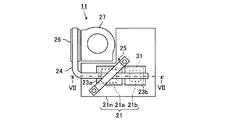
図1は、本実施形態の電子機器10を示す。その電子機器10は、コンピュータ本体11及びディスプレイユニット12を備える。
FIG. 1 shows an
コンピュータ本体11は、薄い箱型の筐体を有している。筐体の上面中央部には入力部としてのキーボード13が設けられる。なお、入力部としては、キーボード13の他に、ポインティングデバイス及び操作スイッチ等が挙げられる。
The computer
また、ディスプレイユニット12には、表示部としてのLCD(liquid crystal display)14が組み込まれている。ディスプレイユニット12は、コンピュータ本体11に対して、開閉軸15を中心として矢印Xの方向に開閉自在となるように、連結部16(ヒンジ)を介して連結される。
The
コンピュータ本体11の内部には、プリント回路板等が設けられる。プリント回路板は、いわゆるシステム基板である。
A printed circuit board or the like is provided inside the computer
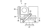
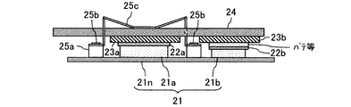
図2は、コンピュータ本体11の内部構造の第1例を示す模式図である。図3は、図2に示すコンピュータ本体11の内部構造の第1例のIII−III断面図である。
FIG. 2 is a schematic diagram showing a first example of the internal structure of the computer
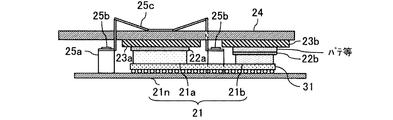
図2及び図3に示すように、コンピュータ本体11は、プリント回路板21、伝熱部材22(図3に示す22a,22b)、放熱部材としてのヒートシンク23(図2及び図3に示す23a,23b)、熱移送部材としてのヒートパイプ24、押圧部材としての板バネ25、熱排出部材としてのフィン26及びファン27によって構成される。
As shown in FIGS. 2 and 3, the computer
プリント回路板21は、対向する第1の面及び第2の面を有するプリント配線板21nと、プリント配線板21nの第1の面上に固定される2つの発熱部品、例えば、CPUチップ21a及びMCH(memory controller hub)チップ21bを備える。CPUチップ21aは、例えばOS(オペレーティングシステム)やアプリケーションソフトウェアを基に演算処理を実施する。MCHチップ21bは、CPUチップ21aとメモリチップ(図示しない)との接続を担う。
The printed
伝熱部材22としては、高熱伝導率の熱伝導グリースや相変化シート等が挙げられる。相変化シートは、室温では固体状態であるが、温度が一定値(60℃程度)以上になると軟化し、発熱部品とヒートシンク23に密着する性質を有している。相変化シートは、発熱部品交換した場合に再使用することが可能であるため、ノートブック型パーソナルコンピュータに適している。発熱部品とヒートシンク23との間に形成された空隙が伝熱部材22より埋められるため、発熱部品とヒートシンク23との間の熱伝達が向上する。 Examples of the heat transfer member 22 include a heat conductive grease having a high heat conductivity and a phase change sheet. The phase change sheet is in a solid state at room temperature, but softens when the temperature reaches a certain value (about 60 ° C.) or more, and has a property of being in close contact with the heat generating component and the heat sink 23. Since the phase change sheet can be reused when the heat-generating component is replaced, it is suitable for a notebook personal computer. Since a gap formed between the heat generating component and the heat sink 23 is filled with the heat transfer member 22, heat transfer between the heat generating component and the heat sink 23 is improved.
ヒートシンク23は、放熱のための金属製の板によって構成される。ヒートシンク23aは、CPUチップ21aの、プリント配線板21nとの固定面に対向する面に伝熱部材22aを介して熱接続され、発熱部品としてのCPUチップ21aを冷却する機能を有する。一方、ヒートシンク23bは、MCHチップ21bの固定面に対向する面に伝熱部材22bを介して熱接続され、発熱部品としてのMCHチップ21bを冷却する機能を有する。CPUチップ21a及びMCHチップ21bから吸収される熱は、ヒートシンク23a,23bの全体にそれぞれ拡散して雰囲気中に放熱されたり、ヒートパイプ24に伝えられたりする。
The heat sink 23 is configured by a metal plate for heat dissipation. The
ヒートパイプ24は、ヒートシンク23aの、CPUチップ21aとの熱接続面に対向する面に、また、ヒートシンク23bの、MCHチップ21bとの熱接続面に対向する面に、ヒートシンク23a,23bに跨って配置される。ヒートパイプ24は、ヒートシンク23a,23b等から伝えられる熱を拡散し、フィン26に移送する機能を有する。ヒートパイプ24の中には冷媒が収容され、液体の蒸発と凝縮の潜熱を利用して排熱を行なう。熱源から徐々に放熱しながら熱を拡散することにより、小さな温度差で大量の熱輸送を可能にする。
The
板バネ25は、プリント配線板21n上に支持され、ヒートパイプ24を複数の発熱部品のうち1つの発熱部品に熱接続されるヒートシンク23に押圧する。板バネ25は、ヒートパイプ24を、例えば、ヒートパイプ24を介してフィン26に最も近い発熱部品(図2及び図3ではCPUチップ21a)に熱接続されるヒートシンク23(図2及び図3ではヒートシンク23a)に押圧する。また、板バネ25は、ヒートパイプ24を、例えば、消費電力が最も高い発熱部品(図2及び図3ではCPUチップ21a)に熱接続されるヒートシンク23(図2及び図3ではヒートシンク23a)に押圧する。これにより、効率よく発熱部品を冷却することが可能になる。
The
板バネ25のプリント配線板21n上への支持方法としては、プリント配線板21n上のCPUチップ21aの1対の角部の各々の外側に固着される支持台25aに、雄ねじ部品25bを介して金属板25cを支持台25aの各々に螺着させる方法がある。支持台25a及び雄ねじ部品25bは、ヒートパイプ24の全体がプリント配線板21nの方に付勢されるように金属板25cを支持している。
As a method of supporting the
フィン26は、ヒートパイプ24に熱接続され、熱交換面積を増やすために交換面がヒレ状に塑性加工される金属によって構成される。フィン26は、ヒートパイプ24から移送される熱を排出する機能を有する。
The
ファン27は、フィン26の近傍に配置される。ファン27は、ヒートパイプ24を介してフィン26に伝えられる熱をコンピュータ本体11の外部に排出する機能を有する。
The
ここで、CPUチップ21aの厚さとMCHチップ21bの厚さとが異なる場合、ヒートパイプ24をヒートシンク23a,23bの両方に接触させることが難しい。そこで、発熱部品からヒートシンク23への熱伝達を向上させるために、厚さの小さい発熱部品(図3ではMCHチップ21b)に相当する伝熱部材22(図3では伝熱部材22b)とヒートシンク23との間にパテ、導熱ゴム部材や、グラファイトシートのような熱拡散シートを備えることが好適である。導熱ゴム部材は、熱伝導性と弾性とを有しており、弾性を備えていればゴム以外の他の部材でも構わない。
Here, when the thickness of the
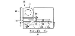
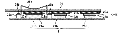
図4は、コンピュータ本体11の内部構造の第2例を示す模式図である。図5は、図4に示すコンピュータ本体11の内部構造の第2例のV−V断面図である。
FIG. 4 is a schematic diagram showing a second example of the internal structure of the computer
図4に示すコンピュータ本体11の内部構造は、図2及び図3に示すコンピュータ本体11の内部構造の第1例に対し、3つの発熱部品に相当する3つのヒートシンク23a,23b,23cに跨って配置されるヒートパイプ24を有する場合のものである。
The internal structure of the computer
プリント回路板21は、プリント配線板21nと、そのプリント配線板21nの表面に固定される3つの発熱部品、例えば、CPUチップ21a、MCHチップ21b及びメモリチップ21cを備える。
The printed
ヒートパイプ24は、ヒートシンク23a,23b,23cに跨って配置され、ヒートシンク23a,23b,23c等から伝えられる熱を拡散し、フィン26に移送する機能を有する。
The
ここで、CPUチップ21aの厚さとMCHチップ21b及びメモリチップ21cの厚さとが異なる場合、ヒートパイプ24をヒートシンク23a,23b,23cの全てに接触させることが難しい。そこで、発熱部品からヒートシンク23への熱伝達を向上させるために、厚さの小さい発熱部品(図5ではMCHチップ21b,メモリチップ21c)に相当する伝熱部材22(図5では伝熱部材22b,22c)とヒートシンク23との間にパテ、導熱ゴム部材や、グラファイトシートのような熱拡散シートを備えることが好適である。導熱ゴム部材は、熱伝導性と弾性とを有しており、弾性を備えていればゴム以外の他の部材でも構わない。
Here, when the thickness of the
なお、図2乃至図5では、コンピュータ本体11の内部構造として、2,3つの発熱部品を有するプリント回路板21を有する場合を例にとって説明するが、4つ以上の発熱部品を有するプリント回路板21を有する場合であってもよい。
2 to 5, an example in which the computer
図6は、コンピュータ本体11の内部構造の第3例を示す模式図である。図7は、図6に示すコンピュータ本体11の内部構造の第3例のVII−VII断面図である。
FIG. 6 is a schematic diagram showing a third example of the internal structure of the computer
図6及び図7に示すコンピュータ本体11のプリント回路板21は、対向する第1の面及び第2の面を有するプリント配線板21nと、プリント配線板21nの第1の面上に固定される1つのパッケージ31と、パッケージ31の、プリント配線板21nとの固定面に対向する面に固定される複数の発熱部品(シリコンダイ)とを備える。1つのパッケージ31上に複数の発熱部品が備えられる場合であっても、図2及び図3を用いて説明したように、板バネ25は、ヒートパイプ24を、パッケージ31に含まれる複数の発熱部品のうち1つの発熱部品に熱接続されるヒートシンク23に押圧する。
The printed
本実施形態の電子機器10によると、複数の発熱部品のうちCPUチップ21a上のヒートパイプ24をCPUチップ21a側に押圧してヒートパイプ24の全体をプリント配線板21nの方に付勢させることで、発熱部品の数に因らずに製作コストを低減し、効率よく熱排出を行なえる。
According to the
10 電子機器
11 コンピュータ本体
21 プリント回路板
21n プリント配線板
21a CPUチップ
21b MCHチップ
21c メモリチップ
22 伝熱部材
23 ヒートシンク
24 ヒートパイプ
25 板バネ
26 フィン
27 ファン
DESCRIPTION OF
Claims (10)
前記プリント配線板の前記第1の面上に固定された複数の発熱部品と、
前記複数の発熱部品の、前記プリント配線板との固定面に対向する面に、前記複数の発熱部品とそれぞれ熱接続された複数の放熱部材と、
前記複数の放熱部材の、前記発熱部品との熱接続面に対向する面に、前記複数の放熱部材に跨って配置された熱移送部材と、
前記プリント配線板に支持され、前記熱移送部材を前記複数の放熱部材のうち1つの放熱部材に押圧した押圧部材と、
前記熱移送部材に熱接続された熱排出部材と、
を備えたことを特徴とする電子機器。 A printed wiring board having opposing first and second surfaces;
A plurality of heat generating components fixed on the first surface of the printed wiring board;
A plurality of heat dissipating members thermally connected to the plurality of heat generating components on the surface of the plurality of heat generating components facing the fixed surface with the printed wiring board,
A heat transfer member disposed across the plurality of heat dissipating members on a surface of the plurality of heat dissipating members facing a heat connection surface with the heat generating component;
A pressing member supported by the printed wiring board and pressing the heat transfer member against one of the plurality of heat radiating members;
A heat exhaust member thermally connected to the heat transfer member;
An electronic device characterized by comprising:
前記プリント配線板の前記第1の面上に固定されたパッケージと、
前記パッケージの、前記プリント配線板との固定面に対向する面に固定された複数の発熱部品と、
前記複数の発熱部品の、前記パッケージとの固定面に対向する面に、前記複数の発熱部品とそれぞれ熱接続される複数の放熱部材と、
前記複数の放熱部材の、前記発熱部品との熱接続面に対向する面に、前記複数の放熱部材に跨って配置された熱移送部材と、
前記プリント配線板に支持され、前記熱移送部材を前記複数の放熱部材のうち1つの放熱部材に押圧した押圧部材と、
前記熱移送部材に熱接続された熱排出部材と、
を備えたことを特徴とする電子機器。 A printed wiring board having opposing first and second surfaces;
A package fixed on the first surface of the printed wiring board;
A plurality of heat generating components fixed to a surface of the package facing a surface fixed to the printed wiring board;
A plurality of heat-dissipating members thermally connected to the plurality of heat-generating components on the surface of the plurality of heat-generating components facing the fixed surface with the package;
A heat transfer member disposed across the plurality of heat dissipating members on a surface of the plurality of heat dissipating members facing a heat connection surface with the heat generating component;
A pressing member supported by the printed wiring board and pressing the heat transfer member against one of the plurality of heat radiating members;
A heat exhaust member thermally connected to the heat transfer member;
An electronic device characterized by comprising:
Priority Applications (1)
| Application Number | Priority Date | Filing Date | Title |
|---|---|---|---|
| JP2008171191A JP4987805B2 (en) | 2008-06-30 | 2008-06-30 | Electronics |
Applications Claiming Priority (1)
| Application Number | Priority Date | Filing Date | Title |
|---|---|---|---|
| JP2008171191A JP4987805B2 (en) | 2008-06-30 | 2008-06-30 | Electronics |
Publications (2)
| Publication Number | Publication Date |
|---|---|
| JP2010010609A true JP2010010609A (en) | 2010-01-14 |
| JP4987805B2 JP4987805B2 (en) | 2012-07-25 |
Family
ID=41590702
Family Applications (1)
| Application Number | Title | Priority Date | Filing Date |
|---|---|---|---|
| JP2008171191A Active JP4987805B2 (en) | 2008-06-30 | 2008-06-30 | Electronics |
Country Status (1)
| Country | Link |
|---|---|
| JP (1) | JP4987805B2 (en) |
Cited By (2)
| Publication number | Priority date | Publication date | Assignee | Title |
|---|---|---|---|---|
| US7986520B2 (en) * | 2009-06-22 | 2011-07-26 | Kabushiki Kaisha Toshiba | Electronic device |
| US10324506B2 (en) | 2015-06-05 | 2019-06-18 | Hewlett Packard Enterprise Development Lp | Thermal management apparatus |
Citations (3)
| Publication number | Priority date | Publication date | Assignee | Title |
|---|---|---|---|---|
| JP2007266518A (en) * | 2006-03-30 | 2007-10-11 | Nec Personal Products Co Ltd | Heat dissipating structure, and information processing apparatus |
| JP2007300029A (en) * | 2006-05-02 | 2007-11-15 | Sony Corp | Semiconductor device, method of manufacturing the same, and circuit substrate device |
| JP2009009316A (en) * | 2007-06-27 | 2009-01-15 | Toshiba Corp | Electronic equipment |
-
2008
- 2008-06-30 JP JP2008171191A patent/JP4987805B2/en active Active
Patent Citations (3)
| Publication number | Priority date | Publication date | Assignee | Title |
|---|---|---|---|---|
| JP2007266518A (en) * | 2006-03-30 | 2007-10-11 | Nec Personal Products Co Ltd | Heat dissipating structure, and information processing apparatus |
| JP2007300029A (en) * | 2006-05-02 | 2007-11-15 | Sony Corp | Semiconductor device, method of manufacturing the same, and circuit substrate device |
| JP2009009316A (en) * | 2007-06-27 | 2009-01-15 | Toshiba Corp | Electronic equipment |
Cited By (2)
| Publication number | Priority date | Publication date | Assignee | Title |
|---|---|---|---|---|
| US7986520B2 (en) * | 2009-06-22 | 2011-07-26 | Kabushiki Kaisha Toshiba | Electronic device |
| US10324506B2 (en) | 2015-06-05 | 2019-06-18 | Hewlett Packard Enterprise Development Lp | Thermal management apparatus |
Also Published As
| Publication number | Publication date |
|---|---|
| JP4987805B2 (en) | 2012-07-25 |
Similar Documents
| Publication | Publication Date | Title |
|---|---|---|
| TWI342486B (en) | Heat-dissipation module and electronic apparatus having the same | |
| US7295437B2 (en) | Heat dissipation device for multiple heat-generating components | |
| TWI399165B (en) | System for efficiently cooling a processor | |
| US8120917B2 (en) | Heat dissipation device | |
| JP5472955B2 (en) | Heat dissipation module | |
| JP2011198868A (en) | Cooling structure for electronic apparatus | |
| US20080291629A1 (en) | Liquid-cooled portable computer | |
| US7487825B2 (en) | Heat dissipation device | |
| US20170083061A1 (en) | Hybrid thermal solution for electronic devices | |
| JP2004047998A (en) | Heat radiator having a plurality of fin types | |
| JP4987805B2 (en) | Electronics | |
| JP4438526B2 (en) | Power component cooling system | |
| TW201916414A (en) | Semiconductor heat conduction and heat dissipation structure capable of rapidly conducting heat generated by operation of a semiconductor and dissipating it through a large area | |
| JP2006339223A (en) | Heat dissipation structure of cpu | |
| TWI745774B (en) | Remote heat exchanging module and composite thin-layered heat conduction structure | |
| US7954541B2 (en) | Heat dissipation module | |
| US7610950B2 (en) | Heat dissipation device with heat pipes | |
| JP6371245B2 (en) | Thermally conductive member, cooling structure and apparatus | |
| JP4549659B2 (en) | Heat sink, housing and cooling fan, and electronic device having heat sink | |
| JP2008091567A (en) | Heat slinger and mounting structure of heat slinger | |
| US20050201059A1 (en) | Heat dissipation device with heat pipes | |
| US20100046171A1 (en) | Fastening member | |
| JP2007165687A (en) | Heat transmission body, and electronic device using same | |
| TWI378343B (en) | A notebook having a heat sink modules | |
| TWI413889B (en) | Heat dissipation device |
Legal Events
| Date | Code | Title | Description |
|---|---|---|---|
| A621 | Written request for application examination |
Free format text: JAPANESE INTERMEDIATE CODE: A621 Effective date: 20101117 |
|
| RD01 | Notification of change of attorney |
Free format text: JAPANESE INTERMEDIATE CODE: A7421 Effective date: 20111202 |
|
| A977 | Report on retrieval |
Free format text: JAPANESE INTERMEDIATE CODE: A971007 Effective date: 20111209 |
|
| A131 | Notification of reasons for refusal |
Free format text: JAPANESE INTERMEDIATE CODE: A131 Effective date: 20120214 |
|
| A521 | Written amendment |
Free format text: JAPANESE INTERMEDIATE CODE: A523 Effective date: 20120314 |
|
| TRDD | Decision of grant or rejection written | ||
| A01 | Written decision to grant a patent or to grant a registration (utility model) |
Free format text: JAPANESE INTERMEDIATE CODE: A01 Effective date: 20120403 |
|
| A01 | Written decision to grant a patent or to grant a registration (utility model) |
Free format text: JAPANESE INTERMEDIATE CODE: A01 |
|
| A61 | First payment of annual fees (during grant procedure) |
Free format text: JAPANESE INTERMEDIATE CODE: A61 Effective date: 20120425 |
|
| R151 | Written notification of patent or utility model registration |
Ref document number: 4987805 Country of ref document: JP Free format text: JAPANESE INTERMEDIATE CODE: R151 |
|
| FPAY | Renewal fee payment (event date is renewal date of database) |
Free format text: PAYMENT UNTIL: 20150511 Year of fee payment: 3 |
|
| S111 | Request for change of ownership or part of ownership |
Free format text: JAPANESE INTERMEDIATE CODE: R313121 Free format text: JAPANESE INTERMEDIATE CODE: R313117 |
|
| R350 | Written notification of registration of transfer |
Free format text: JAPANESE INTERMEDIATE CODE: R350 |