JP2010008538A - Display device - Google Patents
Display device Download PDFInfo
- Publication number
- JP2010008538A JP2010008538A JP2008165522A JP2008165522A JP2010008538A JP 2010008538 A JP2010008538 A JP 2010008538A JP 2008165522 A JP2008165522 A JP 2008165522A JP 2008165522 A JP2008165522 A JP 2008165522A JP 2010008538 A JP2010008538 A JP 2010008538A
- Authority
- JP
- Japan
- Prior art keywords
- transistor
- line
- display
- video data
- video
- Prior art date
- Legal status (The legal status is an assumption and is not a legal conclusion. Google has not performed a legal analysis and makes no representation as to the accuracy of the status listed.)
- Granted
Links
- 239000000758 substrate Substances 0.000 claims description 13
- 239000004973 liquid crystal related substance Substances 0.000 description 40
- 239000010409 thin film Substances 0.000 description 8
- 238000010586 diagram Methods 0.000 description 7
- 229910021420 polycrystalline silicon Inorganic materials 0.000 description 5
- 239000004065 semiconductor Substances 0.000 description 5
- 229920005591 polysilicon Polymers 0.000 description 4
- 238000000034 method Methods 0.000 description 3
- 230000006870 function Effects 0.000 description 2
- 230000002093 peripheral effect Effects 0.000 description 2
- 230000000694 effects Effects 0.000 description 1
- 230000005684 electric field Effects 0.000 description 1
- 239000011159 matrix material Substances 0.000 description 1
- 238000012986 modification Methods 0.000 description 1
- 230000004048 modification Effects 0.000 description 1
Images


Classifications
-
- G—PHYSICS
- G09—EDUCATION; CRYPTOGRAPHY; DISPLAY; ADVERTISING; SEALS
- G09G—ARRANGEMENTS OR CIRCUITS FOR CONTROL OF INDICATING DEVICES USING STATIC MEANS TO PRESENT VARIABLE INFORMATION
- G09G3/00—Control arrangements or circuits, of interest only in connection with visual indicators other than cathode-ray tubes
- G09G3/20—Control arrangements or circuits, of interest only in connection with visual indicators other than cathode-ray tubes for presentation of an assembly of a number of characters, e.g. a page, by composing the assembly by combination of individual elements arranged in a matrix no fixed position being assigned to or needed to be assigned to the individual characters or partial characters
- G09G3/34—Control arrangements or circuits, of interest only in connection with visual indicators other than cathode-ray tubes for presentation of an assembly of a number of characters, e.g. a page, by composing the assembly by combination of individual elements arranged in a matrix no fixed position being assigned to or needed to be assigned to the individual characters or partial characters by control of light from an independent source
- G09G3/36—Control arrangements or circuits, of interest only in connection with visual indicators other than cathode-ray tubes for presentation of an assembly of a number of characters, e.g. a page, by composing the assembly by combination of individual elements arranged in a matrix no fixed position being assigned to or needed to be assigned to the individual characters or partial characters by control of light from an independent source using liquid crystals
- G09G3/3611—Control of matrices with row and column drivers
- G09G3/3648—Control of matrices with row and column drivers using an active matrix
- G09G3/3659—Control of matrices with row and column drivers using an active matrix the addressing of the pixel involving the control of two or more scan electrodes or two or more data electrodes, e.g. pixel voltage dependant on signal of two data electrodes
-
- G—PHYSICS
- G02—OPTICS
- G02F—OPTICAL DEVICES OR ARRANGEMENTS FOR THE CONTROL OF LIGHT BY MODIFICATION OF THE OPTICAL PROPERTIES OF THE MEDIA OF THE ELEMENTS INVOLVED THEREIN; NON-LINEAR OPTICS; FREQUENCY-CHANGING OF LIGHT; OPTICAL LOGIC ELEMENTS; OPTICAL ANALOGUE/DIGITAL CONVERTERS
- G02F1/00—Devices or arrangements for the control of the intensity, colour, phase, polarisation or direction of light arriving from an independent light source, e.g. switching, gating or modulating; Non-linear optics
- G02F1/01—Devices or arrangements for the control of the intensity, colour, phase, polarisation or direction of light arriving from an independent light source, e.g. switching, gating or modulating; Non-linear optics for the control of the intensity, phase, polarisation or colour
- G02F1/13—Devices or arrangements for the control of the intensity, colour, phase, polarisation or direction of light arriving from an independent light source, e.g. switching, gating or modulating; Non-linear optics for the control of the intensity, phase, polarisation or colour based on liquid crystals, e.g. single liquid crystal display cells
- G02F1/133—Constructional arrangements; Operation of liquid crystal cells; Circuit arrangements
- G02F1/136—Liquid crystal cells structurally associated with a semi-conducting layer or substrate, e.g. cells forming part of an integrated circuit
- G02F1/1362—Active matrix addressed cells
- G02F1/13624—Active matrix addressed cells having more than one switching element per pixel
-
- G—PHYSICS
- G09—EDUCATION; CRYPTOGRAPHY; DISPLAY; ADVERTISING; SEALS
- G09G—ARRANGEMENTS OR CIRCUITS FOR CONTROL OF INDICATING DEVICES USING STATIC MEANS TO PRESENT VARIABLE INFORMATION
- G09G2300/00—Aspects of the constitution of display devices
- G09G2300/08—Active matrix structure, i.e. with use of active elements, inclusive of non-linear two terminal elements, in the pixels together with light emitting or modulating elements
- G09G2300/0809—Several active elements per pixel in active matrix panels
- G09G2300/0823—Several active elements per pixel in active matrix panels used to establish symmetry in driving, e.g. with polarity inversion
-
- G—PHYSICS
- G09—EDUCATION; CRYPTOGRAPHY; DISPLAY; ADVERTISING; SEALS
- G09G—ARRANGEMENTS OR CIRCUITS FOR CONTROL OF INDICATING DEVICES USING STATIC MEANS TO PRESENT VARIABLE INFORMATION
- G09G2300/00—Aspects of the constitution of display devices
- G09G2300/08—Active matrix structure, i.e. with use of active elements, inclusive of non-linear two terminal elements, in the pixels together with light emitting or modulating elements
- G09G2300/0809—Several active elements per pixel in active matrix panels
- G09G2300/0842—Several active elements per pixel in active matrix panels forming a memory circuit, e.g. a dynamic memory with one capacitor
- G09G2300/0857—Static memory circuit, e.g. flip-flop
-
- G—PHYSICS
- G09—EDUCATION; CRYPTOGRAPHY; DISPLAY; ADVERTISING; SEALS
- G09G—ARRANGEMENTS OR CIRCUITS FOR CONTROL OF INDICATING DEVICES USING STATIC MEANS TO PRESENT VARIABLE INFORMATION
- G09G2330/00—Aspects of power supply; Aspects of display protection and defect management
- G09G2330/02—Details of power systems and of start or stop of display operation
- G09G2330/021—Power management, e.g. power saving
-
- G—PHYSICS
- G09—EDUCATION; CRYPTOGRAPHY; DISPLAY; ADVERTISING; SEALS
- G09G—ARRANGEMENTS OR CIRCUITS FOR CONTROL OF INDICATING DEVICES USING STATIC MEANS TO PRESENT VARIABLE INFORMATION
- G09G3/00—Control arrangements or circuits, of interest only in connection with visual indicators other than cathode-ray tubes
- G09G3/20—Control arrangements or circuits, of interest only in connection with visual indicators other than cathode-ray tubes for presentation of an assembly of a number of characters, e.g. a page, by composing the assembly by combination of individual elements arranged in a matrix no fixed position being assigned to or needed to be assigned to the individual characters or partial characters
- G09G3/34—Control arrangements or circuits, of interest only in connection with visual indicators other than cathode-ray tubes for presentation of an assembly of a number of characters, e.g. a page, by composing the assembly by combination of individual elements arranged in a matrix no fixed position being assigned to or needed to be assigned to the individual characters or partial characters by control of light from an independent source
- G09G3/36—Control arrangements or circuits, of interest only in connection with visual indicators other than cathode-ray tubes for presentation of an assembly of a number of characters, e.g. a page, by composing the assembly by combination of individual elements arranged in a matrix no fixed position being assigned to or needed to be assigned to the individual characters or partial characters by control of light from an independent source using liquid crystals
- G09G3/3611—Control of matrices with row and column drivers
- G09G3/3614—Control of polarity reversal in general
Landscapes
- Engineering & Computer Science (AREA)
- Chemical & Material Sciences (AREA)
- Crystallography & Structural Chemistry (AREA)
- Physics & Mathematics (AREA)
- Computer Hardware Design (AREA)
- General Physics & Mathematics (AREA)
- Theoretical Computer Science (AREA)
- Liquid Crystal Display Device Control (AREA)
- Control Of Indicators Other Than Cathode Ray Tubes (AREA)
- Liquid Crystal (AREA)
Abstract
Description
本発明は、液晶表示装置やEL表示装置などの表示装置に係り、特に、各表示画素毎にメモリを配置した表示装置に関する。 The present invention relates to a display device such as a liquid crystal display device or an EL display device, and more particularly to a display device in which a memory is arranged for each display pixel.
液晶表示パネル内の各表示画素にメモリ部を配置し、当該メモリ部に表示データを記憶しておき、外部からの入力信号がない場合でも、液晶表示パネルに画像が表示できる、低消費電力で、高機能の液晶表示装置が知られている。(下記、特許文献1参照)
前述の特許文献1に記載した液晶表示装置では、Xアドレス回路及びYアドレス回路を配置し、Xアドレス回路及びYアドレス回路で選択した位置の表示画素のメモリ部に映像データを書き込むものである。
さらに、前述の特許文献1に記載した液晶表示装置は、各表示画素のメモリ部と、Xアドレス回路、およびYアドレス回路とを、半導体層としてポリシリコンを用いた薄膜トランジスタ(以下、Poly-Si TFTという。)を用いて構成し、しかも、液晶表示パネルの各表示画素のメモリ部が形成されている基板と同一の基板上に、Xアドレス回路およびYアドレス回路を一体に構成したものである。
A memory unit is arranged in each display pixel in the liquid crystal display panel, display data is stored in the memory unit, and even when there is no external input signal, an image can be displayed on the liquid crystal display panel with low power consumption. High-performance liquid crystal display devices are known. (See
In the above-described liquid crystal display device described in
Further, the liquid crystal display device described in
なお、本願発明に関連する先行技術文献としては以下のものがある。
液晶表示パネルの各表示画素にメモリ部を配置した液晶表示装置において、各表示画素のメモリ部に記憶されたデータ値を読み出すことが可能であれば、読み出したデータ値を直接他の表示画素のメモリ部に書き込むことにより、ソフトウェアの助けがなくてもハードウェアのみで映像の移動やスクロールが可能である。
しかしながら、例えば、前述の特許文献1等に開示されている、液晶表示パネルの各表示画素にメモリ部を配置した液晶表示装置では、各表示画素のメモリ部に記憶されたデータ値を読み出すことができなかった。
本発明は、前記従来技術の問題点を解決するためになされたものであり、本発明の目的は、各表示画素毎にメモリ部を配置した表示装置において、各表示画素のメモリ部に記憶されたデータ値を読み出すことが可能となる技術を提供することにある。
本発明の前記ならびにその他の目的と新規な特徴は、本明細書の記述及び添付図面によって明らかにする。
In a liquid crystal display device in which a memory unit is arranged in each display pixel of a liquid crystal display panel, if the data value stored in the memory unit of each display pixel can be read, the read data value is directly stored in another display pixel. By writing in the memory section, it is possible to move and scroll the video with only hardware without the assistance of software.
However, for example, in a liquid crystal display device in which a memory unit is arranged in each display pixel of the liquid crystal display panel disclosed in the above-described
The present invention has been made to solve the problems of the prior art, and an object of the present invention is stored in the memory unit of each display pixel in a display device in which a memory unit is arranged for each display pixel. It is an object to provide a technique capable of reading out a data value.
The above and other objects and novel features of the present invention will become apparent from the description of this specification and the accompanying drawings.
本願において開示される発明のうち、代表的なものの概要を簡単に説明すれば、下記の通りである。
(1)複数の表示画素と、前記表示画素に映像データを入力する映像線とを有する表示パネルを備え、前記表示画素は、前記映像データを記憶するメモリ部を有し、前記メモリ部に記憶された前記映像データの保持状態において、前記メモリ部は、入力端子が第1のノードに接続され、出力端子が第2のノードに接続される第1のインバータ回路と、入力端子が前記第2のノードに接続され、出力端子が前記第1のノードに接続される第2のインバータ回路とで構成される表示装置であって、前記表示画素は、前記第2のインバータ回路の前記出力端子と前記映像線との間に接続される第1トランジスタと、前記第1のノードと前記映像線との間に接続される第2トランジスタを有し、前記映像データの読み出し時に、前記第2トランジスタはオフ、前記第1トランジスタはオンとなり、前記メモリ部に記憶された前記映像データを前記映像線に出力し、前記映像データの書き込み時に、前記第1トランジスタはオフ、前記第2トランジスタはオンとなり、前記映像線に供給される前記映像データを前記第1のノードに入力する。
(2)(1)において、前記表示画素は、前記第1のノードと前記第2のインバータ回路の前記出力端子との間に接続される第3トランジスタを有し、前記第3トランジスタは、前記映像データの書き込み・読み出し時にオフ、前記映像データの保存時にオンとなる。
Of the inventions disclosed in this application, the outline of typical ones will be briefly described as follows.
(1) A display panel having a plurality of display pixels and video lines for inputting video data to the display pixels, the display pixel having a memory unit for storing the video data, and storing in the memory unit In the held state of the video data, the memory unit has a first inverter circuit whose input terminal is connected to the first node and whose output terminal is connected to the second node, and whose input terminal is the second node. And a second inverter circuit having an output terminal connected to the first node, wherein the display pixel is connected to the output terminal of the second inverter circuit. A first transistor connected between the video line and a second transistor connected between the first node and the video line, and reading the video data; Off, the first transistor is turned on, the video data stored in the memory unit is output to the video line, and when the video data is written, the first transistor is turned off, the second transistor is turned on, The video data supplied to the video line is input to the first node.
(2) In (1), the display pixel includes a third transistor connected between the first node and the output terminal of the second inverter circuit, and the third transistor includes: Turned off when writing / reading video data, and turned on when saving the video data.
(3)(2)において、前記表示パネルは、論理回路と、1表示ライン毎に設けられ、前記論理回路に接続される第1走査線、第2走査線および第3走査線とを有し、前記第1走査線には第1トランジスタの制御電極が接続され、前記第2走査線には第2トランジスタの制御電極が接続され、前記第3走査線には第3トランジスタの制御電極が接続され、前記論理回路には、前記映像データの書き込み・読み出しを実行する表示ラインを選択する表示ライン選択信号と、前記映像データの読み出しを制御する読み出し制御信号が入力され、前記論理回路は、入力される前記読み出し制御信号と前記表示ライン選択信号とが有効の場合に、前記第1トランジスタをオンとする電圧を前記第1走査線に、前記第2トランジスタと前記第3トランジスタとをオフとする電圧を前記第2走査線と前記第3走査線に出力し、また、入力される前記読み出し制御信号が無効で、前記表示ライン選択信号が有効の場合に、前記第2トランジスタをオンとする電圧を前記第2走査線に、前記第1トランジスタと前記第3トランジスタとをオフとする電圧を前記第1走査線と前記第3走査線に出力する。
(4)(3)において、前記論理回路は、入力される前記読み出し制御信号と前記表示ライン選択信号とが無効の場合に、前記第3トランジスタをオンとする電圧を前記第3走査線に、前記第1トランジスタと前記第2トランジスタとをオフとする電圧を前記第1走査線と前記第2走査線に出力する。
(3) In (2), the display panel includes a logic circuit and a first scan line, a second scan line, and a third scan line provided for each display line and connected to the logic circuit. The control electrode of the first transistor is connected to the first scan line, the control electrode of the second transistor is connected to the second scan line, and the control electrode of the third transistor is connected to the third scan line. The logic circuit is supplied with a display line selection signal for selecting a display line for executing writing / reading of the video data and a read control signal for controlling reading of the video data. When the read control signal and the display line selection signal are valid, a voltage for turning on the first transistor is applied to the first scanning line, and the second transistor and the third transistor are turned on. Output the second scanning line and the third scanning line, and when the input read control signal is invalid and the display line selection signal is valid, the second scanning line is output. A voltage for turning on the transistor is output to the second scanning line, and a voltage for turning off the first transistor and the third transistor is output to the first scanning line and the third scanning line.
(4) In (3), the logic circuit applies, to the third scanning line, a voltage for turning on the third transistor when the read control signal and the display line selection signal input are invalid. A voltage for turning off the first transistor and the second transistor is output to the first scan line and the second scan line.
(5)複数の表示画素と、前記表示画素に映像データを入力する映像線とを有する表示パネルを備え、前記表示画素は、前記映像データを記憶するメモリ部を有し、前記メモリ部に記憶された前記映像データの保持状態において、前記メモリ部は、入力端子が第1のノードに接続され、出力端子が第2のノードに接続される第1のインバータ回路と、入力端子が前記第2のノードに接続され、出力端子が前記第1のノードに接続される第2のインバータ回路とで構成される表示装置であって、前記表示画素は、前記第2のインバータ回路の前記出力端子と前記第1のノードとの間に接続される第1トランジスタと、前記第1トランジスタの第1電極と前記映像線との間に接続される第2トランジスタとを有し、前記映像データの読み出し時に、前記第1トランジスタはオフ、前記第2トランジスタはオンとなり、前記メモリ部に記憶された前記映像データを前記映像線に出力し、前記映像データの書き込み時に、前記第1トランジスタと前記第2トランジスタはオンとなり、前記映像線に供給される前記映像データを前記第1のノードに入力する。
(6)(5)において、
前記表示画素は、前記第1トランジスタの第1電極と前記第2のインバータ回路の前記出力端子との間に接続される第3トランジスタを有し、前記第3トランジスタは、前記映像データの書き込み時にオフ、前記映像データの読み出し・保存時にオンとなる。
(5) A display panel having a plurality of display pixels and video lines for inputting video data to the display pixels, the display pixel having a memory unit for storing the video data, and storing in the memory unit In the held state of the video data, the memory unit has a first inverter circuit whose input terminal is connected to the first node and whose output terminal is connected to the second node, and whose input terminal is the second node. And a second inverter circuit having an output terminal connected to the first node, wherein the display pixel is connected to the output terminal of the second inverter circuit. A first transistor connected to the first node; and a second transistor connected between the first electrode of the first transistor and the video line, and reading the video data The first transistor is turned off, the second transistor is turned on, the video data stored in the memory unit is output to the video line, and when the video data is written, the first transistor and the second transistor are Turns on and inputs the video data supplied to the video line to the first node.
(6) In (5),
The display pixel includes a third transistor connected between a first electrode of the first transistor and the output terminal of the second inverter circuit, and the third transistor is configured to write the video data. Off, turned on when reading / saving the video data.
(7)(6)において、前記表示パネルは、論理回路と、1表示ライン毎に設けられ、前記論理回路に接続される第1走査線、第2走査線および第3走査線とを有し、前記第1走査線には第1トランジスタの制御電極が接続され、前記第2走査線には第2トランジスタの制御電極が接続され、前記第3走査線には第3トランジスタの制御電極が接続され、前記論理回路には、前記映像データの書き込み・読み出しを実行する表示ラインを選択する表示ライン選択信号と、前記映像データの読み出しを制御する読み出し制御信号が入力され、前記論理回路は、入力される前記読み出し制御信号と前記表示ライン選択信号とが有効の場合に、前記第2トランジスタと前記第3トランジスタとをオンとする電圧を前記第2走査線と前記第3走査線に、前記第1トランジスタをオフとする電圧を前記第1走査線に出力し、また、入力される前記読み出し制御信号が無効で、前記表示ライン選択信号が有効の場合に、前記第1トランジスタと前記第2トランジスタとをオンとする電圧を前記第1走査線と前記第2走査線に、前記第3トランジスタをオフとする電圧を前記第3走査線に出力する。
(8)(7)において、前記論理回路は、入力される前記読み出し制御信号と前記表示ライン選択信号とが無効の場合に、前記第1トランジスタと前記第3トランジスタとをオンとする電圧を前記第1走査線と前記第3走査線に、前記第2トランジスタをオフとする電圧を前記第2走査線に出力する。
(7) In (6), the display panel includes a logic circuit and a first scan line, a second scan line, and a third scan line provided for each display line and connected to the logic circuit. The control electrode of the first transistor is connected to the first scan line, the control electrode of the second transistor is connected to the second scan line, and the control electrode of the third transistor is connected to the third scan line. The logic circuit is supplied with a display line selection signal for selecting a display line for executing writing / reading of the video data and a read control signal for controlling reading of the video data. When the read control signal and the display line selection signal are valid, a voltage for turning on the second transistor and the third transistor is applied to the second scan line and the third scan line. A voltage for turning off the first transistor is output to the first scanning line, and the first transistor and the first transistor are output when the input read control signal is invalid and the display line selection signal is valid. A voltage for turning on the two transistors is output to the first scanning line and the second scanning line, and a voltage for turning off the third transistor is output to the third scanning line.
(8) In (7), the logic circuit sets the voltage for turning on the first transistor and the third transistor when the input read control signal and the display line selection signal are invalid. A voltage for turning off the second transistor is output to the second scan line to the first scan line and the third scan line.
(9)(3)、(4)、(7)、または(8)の何れかにおいて、前記表示ライン選択信号を出力する走査線シフトレジスタ回路、あるいは、走査線アドレス回路を有し、前記走査線シフトレジスタ回路、あるいは、前記走査線アドレス回路は、前記表示パネルの前記メモリ部が形成されている基板と同一の基板に一体に形成されていることを特徴とする。
(10)(9)において、前記映像データを供給すべき前記映像線を選択する映像線シフトレジスタ回路、あるいは、映像線アドレス回路を有し、前記映像線シフトレジスタ回路、あるいは、前記映像線アドレス回路は、前記表示パネルの前記メモリ部が形成されている基板と同一の基板に一体に形成されている。
(9) In any one of (3), (4), (7), and (8), the scanning line shift register circuit that outputs the display line selection signal or the scanning line address circuit is provided, and the scanning The line shift register circuit or the scanning line address circuit is integrally formed on the same substrate as the substrate on which the memory portion of the display panel is formed.
(10) In (9), the video line shift register circuit or the video line address circuit for selecting the video line to which the video data is to be supplied is provided, and the video line shift register circuit or the video line address is provided. The circuit is integrally formed on the same substrate as the substrate on which the memory portion of the display panel is formed.
本願において開示される発明のうち代表的なものによって得られる効果を簡単に説明すれば、下記の通りである。
本発明によれば、各表示画素毎にメモリ部を配置した表示装置において、各表示画素のメモリ部に記憶されたデータ値を読み出すことが可能となる。
The effects obtained by the representative ones of the inventions disclosed in the present application will be briefly described as follows.
According to the present invention, in a display device in which a memory unit is arranged for each display pixel, a data value stored in the memory unit of each display pixel can be read.
以下、図面を参照して本発明の実施例を詳細に説明する。
なお、実施例を説明するための全図において、同一機能を有するものは同一符号を付け、その繰り返しの説明は省略する。
[本発明の前提となる液晶表示装置]
図1は、本発明の前提となる液晶表示装置の概略構成を示すブロック図である。
図1において、100は表示部、120はX−アドレス回路(映像線アドレス回路ともいう)、130はY−アドレス回路(走査線アドレス回路ともいう)、10は表示画素である。
表示部100は、マトリクス状に配置される複数個の表示画素10と、各表示画素10に表示データを供給する映像線(ドレイン線ともいう)(D1,D2,D3,...,Dn)と、各表示画素10に走査信号を供給する走査線(ゲート線ともいう)(Y1,Y2,Y3,...YGm)とを有する。
X−アドレス回路120は、n個の出力端子を有し、X−アドレス回路120の各出力端子は、スイッチング素子(SW1,SW2,SW3,...,SWn)を構成する薄膜トランジスタのゲートに接続される。
選択した位置の表示画素10に映像データを書き込む場合、X−アドレス回路120により、スイッチング素子(SW1,SW2,SW3,...,SWn)の中で、選択した位置の表示画素10に対応するスイッチング素子SWをオンとし、映像データが供給されるデータ線(Data)から、映像線(D1,D2,D3,...,Dn)の中の選択した位置の表示画素10に対応する映像線に映像データを供給する。
同様に、Y−アドレス回路130により、走査線(Y1,Y2,Y3,...,Ym)の中の選択した位置の表示画素10に対応する走査線に選択走査電圧を供給する。
Hereinafter, embodiments of the present invention will be described in detail with reference to the drawings.
In all the drawings for explaining the embodiments, parts having the same functions are given the same reference numerals, and repeated explanation thereof is omitted.
[Liquid Crystal Display as a Premise of the Present Invention]
FIG. 1 is a block diagram showing a schematic configuration of a liquid crystal display device as a premise of the present invention.
In FIG. 1, 100 is a display unit, 120 is an X-address circuit (also referred to as a video line address circuit), 130 is a Y-address circuit (also referred to as a scanning line address circuit), and 10 is a display pixel.
The
The
When video data is written to the
Similarly, the Y-
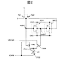
図2は、図1に示す表示画素10の等価回路を示す回路図である。
同図において、第1のインバータ回路(INV1)と、第2のインバータ回路(INV2)は、メモリ部を構成する。
第1のインバータ回路(INV1)は、入力端子がノード1(node1)に接続され、出力端子がノード2(node2)に接続される。また、第2のインバータ回路(INV2)は、入力端子がノード2(node2)に接続され、出力端子がノード1(node1)に接続される。
尚、第2のインバータ回路(INV2)の出力端子はp型トランジスタ(TM2)を介して第1のインバータ回路(INV1)の入力端子と接続されているが、このp型トランジスタ(TM2)は通常の状態、すなわち、メモリ部が保持動作の状態の時はオンになっている。
したがって、p型トランジスタ(TM2)を省略し、第2のインバータ回路(INV2)の出力端子と、第1のインバータ回路(INV1)の入力端子とを直接接続するようにしてもよい。
FIG. 2 is a circuit diagram showing an equivalent circuit of the
In the figure, a first inverter circuit (INV1) and a second inverter circuit (INV2) constitute a memory unit.
The first inverter circuit (INV1) has an input terminal connected to the node 1 (node1) and an output terminal connected to the node 2 (node2). The second inverter circuit (INV2) has an input terminal connected to the node 2 (node2) and an output terminal connected to the node 1 (node1).
The output terminal of the second inverter circuit (INV2) is connected to the input terminal of the first inverter circuit (INV1) via the p-type transistor (TM2). In this state, that is, when the memory section is in the holding operation state, it is turned on.
Therefore, the p-type transistor (TM2) may be omitted, and the output terminal of the second inverter circuit (INV2) and the input terminal of the first inverter circuit (INV1) may be directly connected.
ノード1(node1)に、n型トランジスタ(TM1)のドレインと、p型トランジスタ(TM2)のドレインとが接続され、かつ、n型トランジスタ(TM1)のゲートと、p型トランジスタ(TM2)のゲートが走査線(Y)に接続される。
したがって、走査線(Y)に選択走査電圧、例えば、Highレベル(以下、Hレベルという)が印加されると、n型トランジスタ(TM1)がオン、p型トランジスタ(TM2)がオフとなり、ノード1(node1)に映像線(D)に印加される映像データ(「1」か「0」)が書き込まれる。すなわち、書き込み動作が行われる。
また、走査線(Y)に非選択走査電圧、例えば、Lowレベル(以下、Lレベルという)が印加されると、n型トランジスタ(TM1)がオフ、p型トランジスタ(TM2)がオンとなり、ノード1(node1)に書き込まれたデータ値が、第1のインバータ回路(INV1)と第2のインバータ回路(INV2)とから成るメモリ部に保持される。すなわち、保持動作が行われる。
ゲートがノード1(node1)に接続されるn型トランジスタ(TM3)は、ノード1(node1)の電圧がHレベルの時にオンとなり、画素電極(ITO1)に第1の映像電圧(ここでは、共通電極(ITO2)に印加するVCOMの電圧)を印加する。
ゲートがノード2(node2)に接続されるn型トランジスタ(TM4)は、ノード2(node2)がHレベルの時にオンとなり、画素電極(ITO1)に第2の映像電圧(ここでは、共通電極(ITO2)に印加するVCOMの電圧をインバータで反転したVCOMBの電圧)を印加する。
The drain of the n-type transistor (TM1) and the drain of the p-type transistor (TM2) are connected to the node 1 (node1), and the gate of the n-type transistor (TM1) and the gate of the p-type transistor (TM2) Are connected to the scanning line (Y).
Therefore, when a selected scanning voltage, for example, a high level (hereinafter referred to as an H level) is applied to the scanning line (Y), the n-type transistor (TM1) is turned on and the p-type transistor (TM2) is turned off. Video data (“1” or “0”) applied to the video line (D) is written in (node1). That is, a write operation is performed.
Further, when a non-select scanning voltage, for example, a low level (hereinafter referred to as L level) is applied to the scanning line (Y), the n-type transistor (TM1) is turned off and the p-type transistor (TM2) is turned on. The data value written in 1 (node1) is held in the memory unit including the first inverter circuit (INV1) and the second inverter circuit (INV2). That is, a holding operation is performed.
The n-type transistor (TM3) whose gate is connected to the node 1 (node1) is turned on when the voltage of the node 1 (node1) is at the H level, and the first video voltage (here, common) is applied to the pixel electrode (ITO1). VCOM voltage to be applied to the electrode (ITO2).
The n-type transistor (TM4) whose gate is connected to the node 2 (node2) is turned on when the node 2 (node2) is at the H level, and the second video voltage (here, the common electrode (here, the ITO)) is applied to the pixel electrode (ITO1). The voltage VCOMB obtained by inverting the voltage VCOM applied to the ITO 2) with an inverter is applied.
ノード1(node1)とノード2(node2)との間の関係は、信号レベルが反転した関係にある。そのため、ノード1(node1)の電圧がHレベルの時、ノード2(node2)の電圧はLレベルとなり、n型トランジスタ(TM3)がオン、n型トランジスタ(TM4)はオフとなる。ノード1(node1)の電圧がLレベルの時、ノード2(node2)の電圧はHレベルとなり、n型トランジスタ(TM3)がオフ、n型トランジスタ(TM4)はオンである。
このように、スイッチ部(例えば、同一導電型の2つのトランジスタ(TM3,TM4)で構成される)は、メモリ部に記憶されたデータ(映像線(D)からメモリ部に書き込まれたデータ)に応じて、第1の映像電圧または第2の映像電圧を選択して画素電極(ITO1)に印加する。
画素電極(ITO1)と、これに対向して配置される共通電極(コモン電極、対向電極ともいう)(ITO2)との間に発生する電界によって、液晶(LC)が駆動される。なお、共通電極(ITO2)は、画素電極(ITO1)が形成された基板と同じ基板に形成されていても良いし、異なる基板に形成されていても良い。
The relationship between the node 1 (node 1) and the node 2 (node 2) is a relationship in which the signal level is inverted. Therefore, when the voltage at the node 1 (node1) is at the H level, the voltage at the node 2 (node2) is at the L level, the n-type transistor (TM3) is turned on, and the n-type transistor (TM4) is turned off. When the voltage of the node 1 (node1) is L level, the voltage of the node 2 (node2) is H level, the n-type transistor (TM3) is off, and the n-type transistor (TM4) is on.
In this way, the switch unit (for example, composed of two transistors (TM3, TM4) of the same conductivity type) is stored in the memory unit (data written from the video line (D) to the memory unit). Accordingly, the first video voltage or the second video voltage is selected and applied to the pixel electrode (ITO1).
The liquid crystal (LC) is driven by an electric field generated between the pixel electrode (ITO1) and a common electrode (also referred to as a common electrode or a counter electrode) (ITO2) disposed opposite to the pixel electrode (ITO1). Note that the common electrode (ITO2) may be formed on the same substrate as the substrate on which the pixel electrode (ITO1) is formed, or may be formed on a different substrate.
インバータ回路(INV1,INV2)を構成するトランジスタ、および、TM1,TM2,TM3,TM4のトランジスタは、半導体層としてポリシリコンを用いた薄膜トランジスタで構成される。
図1中のX−アドレス回路120とY−アドレス回路130は、液晶表示パネル内の回路であり、これらの回路は、インバータ回路(INV1,INV2)を構成するトランジスタ、および、TM1,TM2,TM3,TM4のトランジスタと同様、半導体層としてポリシリコンを用いた薄膜トランジスタで構成され、これらの薄膜トランジスタは、インバータ回路(INV1,INV2)を構成するトランジスタ等と同時に形成される。
また、走査線(Y)に非選択走査電圧が印加されると、トランジスタ(TM1)がオフ、トランジスタ(TM2)がオンとなり、ノード1(node1)に書き込まれたデータ値が、第1のインバータ回路(INV1)と第2のインバータ回路(INV2)とから成るメモリ部に保持される。これにより、画像入力がない期間内にも表示部100に画像が表示される。
例えば、ノーマリホワイトの液晶表示パネルの場合、ノード1(node1)に「1」(ノード2(node2)は「0」)が書き込まれたときに「白」、ノード1(node1)に「0」(ノード2(node2)は「1」)が書き込まれた時に「黒」となる。
画像を書き換える必要がない場合には、X−アドレス回路120やY−アドレス回路130の動作を停止できるため、消費電力の低減が可能である。
The transistors constituting the inverter circuit (INV1, INV2) and the transistors TM1, TM2, TM3, TM4 are constituted by thin film transistors using polysilicon as a semiconductor layer.
An
Further, when a non-selection scanning voltage is applied to the scanning line (Y), the transistor (TM1) is turned off and the transistor (TM2) is turned on, and the data value written in the node 1 (node1) becomes the first inverter. The data is held in a memory unit including a circuit (INV1) and a second inverter circuit (INV2). Thus, an image is displayed on the
For example, in the case of a normally white liquid crystal display panel, “1” (node 2 (node 2) is “0”) is written to node 1 (node 1), “white”, and node 1 (node 1) is “0”. "(Node 2 (node2) is" 1 ") becomes" black ".
When it is not necessary to rewrite the image, the operation of the
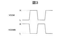
図3は、図2に示すVCOMの電圧と、VCOMの電圧を反転したバーVCOMの電圧の反転周期を説明するための図である。
図1に示す液晶表示装置の交流駆動方法としてコモン反転駆動方法が採用されるが、図1に示す液晶表示装置では、図3に示すように、VCOMの電圧(第1の映像電圧)と、VCOMの電圧を反転したVCOMBの電圧(第2の映像電圧)とを、コモン反転周期に応じて変化させるだけよい。VCOMの電圧は、コモン反転周期に応じて、Lレベル(例えば、0V)と、Hレベル(例えば、5V)との間で反転する。VCOMBの電圧は、VCOMの電圧をインバータで反転して生成することができる。VCOMの電圧がLレベルの時、VCOMBの電圧はHレベルであり、VCOMの電圧がHレベルの時、VCOMBの電圧はLレベルである。すなわち、所定の周期でVCOMの電圧の大きさとVCOMBの電圧の大きさとが互いに入れ替わる。
FIG. 3 is a diagram for explaining the VCOM voltage shown in FIG. 2 and the inversion period of the bar VCOM voltage obtained by inverting the VCOM voltage.
A common inversion driving method is adopted as an AC driving method of the liquid crystal display device shown in FIG. 1, but in the liquid crystal display device shown in FIG. 1, as shown in FIG. 3, a VCOM voltage (first video voltage), It is only necessary to change the VCOMB voltage (second video voltage) obtained by inverting the VCOM voltage in accordance with the common inversion period. The voltage of VCOM is inverted between the L level (for example, 0 V) and the H level (for example, 5 V) according to the common inversion period. The voltage VCOMB can be generated by inverting the voltage VCOM with an inverter. When the voltage of VCOM is L level, the voltage of VCOMB is H level, and when the voltage of VCOM is H level, the voltage of VCOMB is L level. That is, the magnitude of the voltage VCOM and the magnitude of the voltage VCOMB are interchanged with each other at a predetermined cycle.
[実施例1]
図4は、本発明の実施例1の液晶表示装置の概略構成を示す図である。
本実施例の液晶表示装置は、液晶表示パネル内の各表示画素にメモリ部を配置し、当該メモリ部に表示データを記憶しておき、外部からの入力信号がない場合でも、液晶表示パネルに画像が表示できる、低消費電力で、高機能の液晶表示装置において、メモリ部に記憶されたデータ値を読み出せるようにしたものである。
本実施例において、図1に示す液晶表示装置と異なる点は、以下の点である。
(1)メモリ部に記憶されたデータ値の読み出し用にトランジスタ(TM5)が追加され、このトランジスタ(TM5)は、映像線(D)と第2のインバータ回路(INV2)の出力端子との間に接続される点
(2)1表示ライン毎の走査線が1本から、G1,G2,G3の3本に変更され、トランジスタ(TM5)のゲートは第1の走査線(G1)に接続され、トランジスタ(TM1)のゲートは第2の走査線(G2)に接続され、トランジスタ(TM6)のゲートは第3の走査線(G3)に接続される点
(3)第1の走査線(G1)、第2の走査線(G2)、および、第3の走査線(G3)は、論理回路50に接続される点
(4)新たに、読み出し制御信号(RD)が追加され、論理回路50に入力される点
[Example 1]
FIG. 4 is a diagram showing a schematic configuration of the liquid crystal display device according to
In the liquid crystal display device of this embodiment, a memory unit is arranged in each display pixel in the liquid crystal display panel, display data is stored in the memory unit, and even when there is no input signal from the outside, the liquid crystal display panel In a liquid crystal display device with low power consumption and high functionality capable of displaying an image, a data value stored in a memory unit can be read.
The present embodiment is different from the liquid crystal display device shown in FIG. 1 in the following points.
(1) A transistor (TM5) is added for reading the data value stored in the memory unit, and this transistor (TM5) is connected between the video line (D) and the output terminal of the second inverter circuit (INV2). (2) The number of scanning lines for each display line is changed from one to three, G1, G2, and G3, and the gate of the transistor (TM5) is connected to the first scanning line (G1). The gate of the transistor (TM1) is connected to the second scanning line (G2), and the gate of the transistor (TM6) is connected to the third scanning line (G3). (3) The first scanning line (G1) ), The second scanning line (G2), and the third scanning line (G3) are connected to the logic circuit 50 (4). A read control signal (RD) is newly added to the
本実施例では、論理回路50は、Y−アドレス回路130から出力される表示ライン選択信号(Hレベルの選択走査電圧、あるいは、Lレベルの非選択走査電圧)(YL)と、読み出し制御信号(RD)との論理積を取って第1の走査線(G1)に出力するアンド回路33と、Y−アドレス回路130から出力される表示ライン選択信号と、インバータ回路30で反転された読み出し制御信号(RD)の反転信号との論理積を取って第2の走査線(G2)に出力するアンド回路32と、Y−アドレス回路130から出力される表示ライン選択信号を反転して第3の走査線(G3)に出力するインバータ回路31とで構成される。
なお、本実施例1、および後述する実施例2のX−アドレス回路120とY−アドレス回路130は、液晶表示パネル内の回路であり、これらの回路は、インバータ回路(INV1,INV2)を構成するトランジスタ、および、TM1,TM3,TM4,TM5,TM6のトランジスタと同様、半導体層がポリシリコン層から成る薄膜トランジスタで構成され、これらの薄膜トランジスタは、インバータ回路(INV1,INV2)を構成するトランジスタ等と同時に形成される。
また、本実施例では、図2に示すp型トランジスタ(TM2)に代えて、n型トランジスタ(TM6)が使用されが、図2と同様、p型トランジスタ(TM2)を使用することも可能である。その場合、インバータ回路31は必要ない。
また、本実施例において、X−アドレス回路120に代えて、X−シフトレジスタ回路を使用してもよく、また、Y−アドレス回路130に代えて、Y−シフトレジスタ回路を使用してもよい。
In this embodiment, the
The
In this embodiment, an n-type transistor (TM6) is used instead of the p-type transistor (TM2) shown in FIG. 2, but a p-type transistor (TM2) can also be used as in FIG. is there. In that case, the
In this embodiment, an X-shift register circuit may be used instead of the
以下、本実施例の液晶表示装置の動作を、図5のタイミングチャートを用いて説明する。 初めに、メモリ部に記憶されたデータ値の読み出しについて説明する。
メモリ部に記憶されたデータ値を読み出す時には、図5(a)に示すように、Y−アドレス回路130で読み出す表示ラインを選択する。ここでは、1番目の表示ライン(YL1)を選択し、表示ライン選択信号を有効とするため、Hレベルの選択走査電圧を出力する。
次に、図5(a)に示すように、読み出し制御信号(RD)を有効とするためHレベルとする。これにより、論理回路50内の、インバータ回路31、アンド回路32、アンド回路33から、第1の走査線(G1)、第2の走査線(G2)、および、第3の走査線(G3)に、図5(a)に示す電圧が出力される。
この時、第1の走査線(G1)はHレベル、第2の走査線(G2)と第3の走査線(G3)はLowレベルとなるので、トランジスタ(TM5)はオン、トランジスタ(TM1)とトランジスタ(TM6)はオフとなる。
したがって、映像線(D)に、メモリ部に記憶されたデータ値(第2のインバータ(INV2)の出力電圧)が読み出される。
Hereinafter, the operation of the liquid crystal display device of this embodiment will be described with reference to the timing chart of FIG. First, reading of data values stored in the memory unit will be described.
When the data value stored in the memory unit is read, the display line read by the Y-
Next, as shown in FIG. 5A, the read control signal (RD) is set to the H level to make it valid. As a result, the first scanning line (G1), the second scanning line (G2), and the third scanning line (G3) from the
At this time, the first scanning line (G1) is at the H level and the second scanning line (G2) and the third scanning line (G3) are at the low level, so that the transistor (TM5) is on and the transistor (TM1) And the transistor (TM6) is turned off.
Therefore, the data value (the output voltage of the second inverter (INV2)) stored in the memory unit is read to the video line (D).
次に、この映像線(D)に読み出されたデータ値を、他のメモリ部に書き込むには、まず、図5(b)に示すように、Y−アドレス回路130で書き込む表示ラインを選択する。ここでは、n番目の表示ライン(YLn)を選択し、表示ライン選択信号を有効とするため、Hレベルの選択走査電圧を出力する。
また、書き込み時には、図5(b)に示すように、読み出し制御信号(RD)をLレベルのままとする。これにより、論理回路50内の、インバータ回路31、アンド回路32、アンド回路33から、第1の走査線(G1)、第2の走査線(G2)、および、第3の走査線(G3)に、図5(b)に示す電圧が出力される。
この時、第2の走査線(G2)はHレベル、第1の走査線(G1)と第3の走査線(G3)はLレベルとなるので、トランジスタ(TM1)はオン、トランジスタ(TM5)とトランジスタ(TM6)はオフとなる。
これにより、読み出したデータ値(即ち、1番目の表示ライン(YL1)のメモリ部に記録されたデータ値)が、n番目の表示ライン(YLn)のメモリ部に書き込まれる。このようにして、データの移動が行なはれ、これを連続で行うことによりスクロールを行うことができる。
Next, in order to write the data value read to the video line (D) to another memory unit, first, as shown in FIG. 5B, the display line to be written by the Y-
At the time of writing, as shown in FIG. 5B, the read control signal (RD) is kept at the L level. As a result, the first scanning line (G1), the second scanning line (G2), and the third scanning line (G3) from the
At this time, since the second scanning line (G2) is at the H level and the first scanning line (G1) and the third scanning line (G3) are at the L level, the transistor (TM1) is on and the transistor (TM5) is on. And the transistor (TM6) is turned off.
As a result, the read data value (that is, the data value recorded in the memory portion of the first display line (YL1)) is written into the memory portion of the nth display line (YLn). In this way, the data can be moved and scrolling can be performed by continuously performing the data movement.
[実施例2]
図6は、本発明の実施例2の液晶表示装置の概略構成を示す図である。
本実施例において、図4に示す液晶表示装置と異なる点は、以下の点である。
(1)メモリ部に記憶されたデータ値の読み出し用に追加されたトランジスタ(TM5)が、トランジスタ(TM1)のドレインと第1のノード(node1)との間に接続される点
(2)論理回路51は、Y−アドレス回路130から出力される表示ライン選択信号(Hレベルの選択走査電圧、あるいは、Lレベルの非選択走査電圧)(YL)と、読み出し制御信号(RD)との一致を取って第3の走査線(G3)に出力する一致回路34と、読み出し制御信号(RD)を反転して第1の走査線(G1)に出力するインバータ回路33とで構成される。また、第2の走査線(G2)に対しては、Y−アドレス回路130から出力される表示ライン選択信号(YL)が出力される。
また、本実施例では、図2に示すp型トランジスタ(TM2)に代えて、n型トランジスタ(TM6)が使用されが、図2と同様、p型トランジスタ(TM2)を使用することも可能である。その場合、一致回路34に代えて、EX−OR回路を用いればよい。
また、本実施例においても、X−アドレス回路120に代えて、X−シフトレジスタ回路を使用してもよく、また、Y−アドレス回路130に代えて、Y−シフトレジスタ回路を使用してもよい。
[Example 2]
FIG. 6 is a diagram showing a schematic configuration of a liquid crystal display device according to
The present embodiment is different from the liquid crystal display device shown in FIG. 4 in the following points.
(1) The transistor (TM5) added for reading the data value stored in the memory unit is connected between the drain of the transistor (TM1) and the first node (node1). (2) Logic The
In this embodiment, an n-type transistor (TM6) is used instead of the p-type transistor (TM2) shown in FIG. 2, but a p-type transistor (TM2) can also be used as in FIG. is there. In that case, an EX-OR circuit may be used instead of the
Also in this embodiment, an X-shift register circuit may be used instead of the
以下、本実施例の液晶表示装置の動作を、図7のタイミングチャートを用いて説明する。 初めに、メモリ部に記憶されたデータ値の読み出しについて説明する。
メモリ部に記憶されたデータ値を読み出す時には、図7(a)に示すように、Y−アドレス回路130で読み出す表示ラインを選択する。ここでは、1番目の表示ライン(YL1)を選択し、表示ライン選択信号を有効とするため、Hレベルの選択走査電圧を出力する。
次に、図7(a)に示すように、読み出し制御信号(RD)を有効とするためHレベルとする。これにより、論理回路51内の、インバータ回路35、一致回路34から、第1の走査線(G1)と、第3の走査線(G3)に、図7(a)に示す電圧が出力される。また、第2の走査線(G2)には、図7(a)に示すように、Hレベルの選択走査電圧が出力される。
この時、第2の走査線(G2)と第3の走査線(G3)はHレベル、第1の走査線(G1)はLowレベルとなるので、トランジスタ(TM5)はオフ、トランジスタ(TM1)とトランジスタ(TM6)はオンとなる。
したがって、映像線(D)に、メモリ部に記憶されたデータ値(第2のインバータ(INV2)の出力電圧)が読み出される。
Hereinafter, the operation of the liquid crystal display device of this embodiment will be described with reference to the timing chart of FIG. First, reading of data values stored in the memory unit will be described.
When the data value stored in the memory unit is read, the display line read by the Y-
Next, as shown in FIG. 7A, the read control signal (RD) is set to the H level to make it valid. Thereby, the voltage shown in FIG. 7A is output from the
At this time, the second scanning line (G2) and the third scanning line (G3) are at the H level, and the first scanning line (G1) is at the low level. Therefore, the transistor (TM5) is turned off and the transistor (TM1) is turned off. And the transistor (TM6) is turned on.
Therefore, the data value (the output voltage of the second inverter (INV2)) stored in the memory unit is read to the video line (D).
次に、この映像線(D)に読み出されたデータ値を、他のメモリ部に書き込むには、まず、図7(b)に示すように、Y−アドレス回路130で書き込む表示ラインを選択する。ここでは、n番目の表示ライン(YLn)を選択し、表示ライン選択信号を有効とするため、Hレベルの選択走査電圧を出力する。
また、書き込み時には、図7(b)に示すように、読み出し制御信号(RD)をLレベルのままとする。これにより、論理回路51内の、インバータ回路35、一致回路34から、第1の走査線(G1)と、第3の走査線(G3)に、図7(b)に示す電圧が出力される。また、第2の走査線(G2)には、図7(b)に示すように、Hレベルの選択走査電圧が出力される。
この時、第1の走査線(G1)と第2の走査線(G2)はHレベル、第3の走査線(G3)はLowレベルとなるので、トランジスタ(TM6)はオフ、トランジスタ(TM1)とトランジスタ(TM5)はオンとなる。
これにより、読み出したデータ値(即ち、1番目の表示ライン(YL1)のメモリ部に記録されたデータ値)が、n番目の表示ライン(YLn)のメモリ部に書き込まれる。このようにして、データの移動が行なはれ、これを連続で行うことによりスクロールを行うことができる。
Next, in order to write the data value read to the video line (D) to another memory unit, first, as shown in FIG. 7B, the display line to be written by the Y-
At the time of writing, as shown in FIG. 7B, the read control signal (RD) is kept at the L level. Accordingly, the voltage shown in FIG. 7B is output from the
At this time, since the first scanning line (G1) and the second scanning line (G2) are at the H level and the third scanning line (G3) is at the Low level, the transistor (TM6) is turned off and the transistor (TM1) is turned off. And the transistor (TM5) is turned on.
As a result, the read data value (that is, the data value recorded in the memory portion of the first display line (YL1)) is written into the memory portion of the nth display line (YLn). In this way, the data can be moved and scrolling can be performed by continuously performing the data movement.
以上説明したように、本実施例によれば、各表示画素のメモリ部に記録されたデータ値を読み出すことができるため、それを直接他の表示画素のメモリ部に書き込むことにより、ソフトウェアの助けがなくてもハードウェアのみで映像の移動やスクロールができる。これにより、描画速度の向上や表示時の電力低減を図ることが可能となる。
なお、前述の実施例では、本発明を液晶表示装置に適用した場合について説明したが、本発明はこれに限定されるものではなく、本発明は、EL表示装置など(有機EL表示装置など)にも適用可能であることはいうまでもない。
また、前述の実施例では、周辺回路(例えば、X−アドレス回路120、あるいは、Y−アドレス回路130)を、液晶表示パネルに内蔵(液晶表示パネルの基板上に一体に形成)した場合について説明しているが、本発明はこれに限定されるものではなく、周辺回路の一部の機能を半導体チップを用いて構成しても良い。
さらに、前述の実施例では、薄膜トランジスタとしてMOSトランジスタを用いた場合について説明しているが、MOSトランジスタよりも広い概念であるMISトランジスタを用いても良い。
以上、本発明者によってなされた発明を、前記実施例に基づき具体的に説明したが、本発明は、前記実施例に限定されるものではなく、その要旨を逸脱しない範囲において種々変更可能であることは勿論である。
As described above, according to the present embodiment, since the data value recorded in the memory unit of each display pixel can be read out, it is possible to assist the software by writing it directly into the memory unit of another display pixel. Even if there is no video, you can move and scroll the video with only hardware. Thereby, it is possible to improve the drawing speed and reduce the power during display.
In the above-described embodiments, the case where the present invention is applied to a liquid crystal display device has been described. However, the present invention is not limited to this, and the present invention includes an EL display device and the like (organic EL display device and the like). Needless to say, this is also applicable.
Further, in the above-described embodiment, a case where a peripheral circuit (for example, the
Furthermore, in the above-described embodiment, the case where a MOS transistor is used as the thin film transistor has been described. However, a MIS transistor having a wider concept than the MOS transistor may be used.
As mentioned above, the invention made by the present inventor has been specifically described based on the above embodiments. However, the present invention is not limited to the above embodiments, and various modifications can be made without departing from the scope of the invention. Of course.
10 表示画素
30,31,35,INV1,INV2 インバータ回路
32,33 アンド回路
34 一致回路
50,51 論理回路
100 表示部
120 X−アドレス回路
130 Y−アドレス回路
Data データ線
D,D1,D2,D3,...,Dn 映像線
Y,Y1,Y2,Y3,...,Ym 走査線
G1 第1の走査線
G2 第2の走査線
G3 第3の走査線
SW1,SW2,SW3,...,SWn スイッチング素子
node1 ノード1
node2 ノード2
TM2 p型トランジスタ
TM1,TM3,TM4,TM5,TM6 n型トランジスタ
ITO1 画素電極
ITO2 共通電極
LC 液晶
DESCRIPTION OF
TM2 p-type transistor TM1, TM3, TM4, TM5, TM6 n-type transistor ITO1 pixel electrode ITO2 common electrode LC liquid crystal
Claims (10)
前記表示画素に映像データを入力する映像線とを有する表示パネルを備え、
前記表示画素は、前記映像データを記憶するメモリ部を有し、
前記メモリ部に記憶された前記映像データの保持状態において、前記メモリ部は、入力端子が第1のノードに接続され、出力端子が第2のノードに接続される第1のインバータ回路と、
入力端子が前記第2のノードに接続され、出力端子が前記第1のノードに接続される第2のインバータ回路とで構成される表示装置であって、
前記表示画素は、前記第2のインバータの前記出力端子と前記映像線との間に接続される第1トランジスタと、
前記第1のノードと前記映像線との間に接続される第2トランジスタを有し、
前記映像データの読み出し時に、前記第2トランジスタはオフ、前記第1トランジスタはオンとなり、前記メモリ部に記憶された前記映像データを前記映像線に出力し、
前記映像データの書き込み時に、前記第1トランジスタはオフ、前記第2トランジスタはオンとなり、前記映像線に供給される前記映像データを前記第1のノードに入力することを特徴とする表示装置。 A plurality of display pixels;
A display panel having a video line for inputting video data to the display pixel,
The display pixel has a memory unit for storing the video data,
In the holding state of the video data stored in the memory unit, the memory unit includes a first inverter circuit having an input terminal connected to the first node and an output terminal connected to the second node;
A display device including an input terminal connected to the second node and an output terminal connected to the first node;
The display pixel includes a first transistor connected between the output terminal of the second inverter and the video line;
A second transistor connected between the first node and the video line;
At the time of reading the video data, the second transistor is turned off, the first transistor is turned on, and the video data stored in the memory unit is output to the video line,
When the video data is written, the first transistor is turned off and the second transistor is turned on, and the video data supplied to the video line is input to the first node.
前記第3トランジスタは、前記映像データの書き込み・読み出し時にオフ、前記映像データの保存時にオンとなることを特徴とする請求項1に記載の表示装置。 The display pixel includes a third transistor connected between the first node and the output terminal of the second inverter circuit,
The display device according to claim 1, wherein the third transistor is turned off when the video data is written / read, and turned on when the video data is stored.
1表示ライン毎に設けられ、前記論理回路に接続される第1走査線、第2走査線および第3走査線とを有し、
前記第1走査線には第1トランジスタの制御電極が接続され、
前記第2走査線には第2トランジスタの制御電極が接続され、
前記第3走査線には第3トランジスタの制御電極が接続され、
前記論理回路には、前記映像データの書き込み・読み出しを実行する表示ラインを選択する表示ライン選択信号と、前記映像データの読み出しを制御する読み出し制御信号が入力され、
前記論理回路は、入力される前記読み出し制御信号と前記表示ライン選択信号とが有効の場合に、前記第1トランジスタをオンとする電圧を前記第1走査線に、前記第2トランジスタと前記第3トランジスタとをオフとする電圧を前記第2走査線と前記第3走査線に出力し、また、入力される前記読み出し制御信号が無効で、前記表示ライン選択信号が有効の場合に、前記第2トランジスタをオンとする電圧を前記第2走査線に、前記第1トランジスタと前記第3トランジスタとをオフとする電圧を前記第1走査線と前記第3走査線に出力することを特徴とする請求項2に記載の表示装置。 The display panel includes a logic circuit,
A first scan line, a second scan line, and a third scan line provided for each display line and connected to the logic circuit;
A control electrode of a first transistor is connected to the first scan line,
A control electrode of a second transistor is connected to the second scan line,
A control electrode of a third transistor is connected to the third scan line,
The logic circuit receives a display line selection signal for selecting a display line for performing writing / reading of the video data, and a read control signal for controlling reading of the video data,
The logic circuit applies a voltage for turning on the first transistor to the first scanning line, the second transistor, and the third transistor when the input read control signal and the display line selection signal are valid. When the voltage for turning off the transistor is output to the second scanning line and the third scanning line, and the read control signal input is invalid and the display line selection signal is valid, the second scanning line is output. A voltage for turning on a transistor is output to the second scanning line, and a voltage for turning off the first transistor and the third transistor is output to the first scanning line and the third scanning line. Item 3. The display device according to Item 2.
前記表示画素に映像データを入力する映像線とを有する表示パネルを備え、
前記表示画素は、前記映像データを記憶するメモリ部を有し、
前記メモリ部に記憶された前記映像データの保持状態において、前記メモリ部は、入力端子が第1のノードに接続され、出力端子が第2のノードに接続される第1のインバータ回路と、
入力端子が前記第2のノードに接続され、出力端子が前記第1のノードに接続される第2のインバータ回路とで構成される表示装置であって、
前記表示画素は、前記第2のインバータの前記出力端子と前記第1のノードとの間に接続される第1トランジスタと、
前記第1トランジスタの第1電極と前記映像線との間に接続される第2トランジスタとを有し、
前記映像データの読み出し時に、前記第1トランジスタはオフ、前記第2トランジスタはオンとなり、前記メモリ部に記憶された前記映像データを前記映像線に出力し、
前記映像データの書き込み時に、前記第1トランジスタと前記第2トランジスタはオンとなり、前記映像線に供給される前記映像データを前記第1のノードに入力することを特徴とする表示装置。 A plurality of display pixels;
A display panel having a video line for inputting video data to the display pixel,
The display pixel has a memory unit for storing the video data,
In the holding state of the video data stored in the memory unit, the memory unit includes a first inverter circuit having an input terminal connected to the first node and an output terminal connected to the second node;
A display device including an input terminal connected to the second node and an output terminal connected to the first node;
The display pixel includes a first transistor connected between the output terminal of the second inverter and the first node;
A second transistor connected between the first electrode of the first transistor and the video line;
At the time of reading the video data, the first transistor is turned off, the second transistor is turned on, and the video data stored in the memory unit is output to the video line,
The display device according to claim 1, wherein when the video data is written, the first transistor and the second transistor are turned on, and the video data supplied to the video line is input to the first node.
前記第3トランジスタは、前記映像データの書き込み時にオフ、前記映像データの読み出し・保存時にオンとなることを特徴とする請求項5に記載の表示装置。 The display pixel includes a third transistor connected between the first electrode of the first transistor and the output terminal of the second inverter circuit,
The display device according to claim 5, wherein the third transistor is turned off when the video data is written and turned on when the video data is read / stored.
1表示ライン毎に設けられ、前記論理回路に接続される第1走査線、第2走査線および第3走査線とを有し、
前記第1走査線には第1トランジスタの制御電極が接続され、
前記第2走査線には第2トランジスタの制御電極が接続され、
前記第3走査線には第3トランジスタの制御電極が接続され、
前記論理回路には、前記映像データの書き込み・読み出しを実行する表示ラインを選択する表示ライン選択信号と、前記映像データの読み出しを制御する読み出し制御信号が入力され、
前記論理回路は、入力される前記読み出し制御信号と前記表示ライン選択信号とが有効の場合に、前記第2トランジスタと前記第3トランジスタとをオンとする電圧を前記第2走査線と前記第3走査線に、前記第1トランジスタをオフとする電圧を前記第1走査線に出力し、また、入力される前記読み出し制御信号が無効で、前記表示ライン選択信号が有効の場合に、前記第1トランジスタと前記第2トランジスタとをオンとする電圧を前記第1走査線と前記第2走査線に、前記第3トランジスタをオフとする電圧を前記第3走査線に出力することを特徴とする請求項6に記載の表示装置。 The display panel includes a logic circuit,
A first scan line, a second scan line, and a third scan line provided for each display line and connected to the logic circuit;
A control electrode of a first transistor is connected to the first scan line,
A control electrode of a second transistor is connected to the second scan line,
A control electrode of a third transistor is connected to the third scan line,
The logic circuit receives a display line selection signal for selecting a display line for performing writing / reading of the video data, and a read control signal for controlling reading of the video data,
The logic circuit generates a voltage for turning on the second transistor and the third transistor when the input read control signal and the display line selection signal are valid. When the voltage for turning off the first transistor is output to the scanning line to the first scanning line and the read control signal input is invalid and the display line selection signal is valid, the first A voltage for turning on a transistor and the second transistor is output to the first scanning line and the second scanning line, and a voltage for turning off the third transistor is output to the third scanning line. Item 7. The display device according to Item 6.
前記走査線シフトレジスタ回路、あるいは、前記走査線アドレス回路は、前記表示パネルの前記メモリ部が形成されている基板と同一の基板に一体に形成されていることを特徴とする請求項3、請求項4、請求項7、または、請求項8のいずれか1項に記載の表示装置。 A scanning line shift register circuit that outputs the display line selection signal, or a scanning line address circuit;
4. The scanning line shift register circuit or the scanning line address circuit is integrally formed on the same substrate as the substrate on which the memory portion of the display panel is formed. The display device according to claim 4, claim 7, or claim 8.
前記映像線シフトレジスタ回路、あるいは、前記映像線アドレス回路は、前記表示パネルの前記メモリ部が形成されている基板と同一の基板に一体に形成されていることを特徴とする請求項9に記載の表示装置。 A video line shift register circuit for selecting the video line to be supplied with the video data, or a video line address circuit;
10. The video line shift register circuit or the video line address circuit is integrally formed on the same substrate as the substrate on which the memory unit of the display panel is formed. Display device.
Priority Applications (2)
| Application Number | Priority Date | Filing Date | Title |
|---|---|---|---|
| JP2008165522A JP5161670B2 (en) | 2008-06-25 | 2008-06-25 | Display device |
| US12/490,469 US8339351B2 (en) | 2008-06-25 | 2009-06-24 | Display device |
Applications Claiming Priority (1)
| Application Number | Priority Date | Filing Date | Title |
|---|---|---|---|
| JP2008165522A JP5161670B2 (en) | 2008-06-25 | 2008-06-25 | Display device |
Publications (2)
| Publication Number | Publication Date |
|---|---|
| JP2010008538A true JP2010008538A (en) | 2010-01-14 |
| JP5161670B2 JP5161670B2 (en) | 2013-03-13 |
Family
ID=41446803
Family Applications (1)
| Application Number | Title | Priority Date | Filing Date |
|---|---|---|---|
| JP2008165522A Active JP5161670B2 (en) | 2008-06-25 | 2008-06-25 | Display device |
Country Status (2)
| Country | Link |
|---|---|
| US (1) | US8339351B2 (en) |
| JP (1) | JP5161670B2 (en) |
Cited By (2)
| Publication number | Priority date | Publication date | Assignee | Title |
|---|---|---|---|---|
| WO2011102349A1 (en) * | 2010-02-19 | 2011-08-25 | シャープ株式会社 | Liquid crystal display device, display method, display programme, and computer readable recording medium |
| CN108873530A (en) * | 2018-07-30 | 2018-11-23 | 京东方科技集团股份有限公司 | A kind of array substrate, display panel and display device |
Families Citing this family (2)
| Publication number | Priority date | Publication date | Assignee | Title |
|---|---|---|---|---|
| JP2015197719A (en) * | 2014-03-31 | 2015-11-09 | シナプティクス・ディスプレイ・デバイス合同会社 | Power supply circuit, display panel driver and display device |
| CN108597468B (en) | 2018-04-26 | 2019-12-06 | 京东方科技集团股份有限公司 | Pixel circuit, driving method thereof, display panel, display device and storage medium |
Citations (7)
| Publication number | Priority date | Publication date | Assignee | Title |
|---|---|---|---|---|
| JP2002207453A (en) * | 2001-01-04 | 2002-07-26 | Hitachi Ltd | Image display device and its driving method |
| JP2002287718A (en) * | 2001-01-18 | 2002-10-04 | Sharp Corp | Display device, portable appliance and substrate |
| JP2007034095A (en) * | 2005-07-29 | 2007-02-08 | Hitachi Displays Ltd | Display device |
| JP2007041610A (en) * | 2006-09-08 | 2007-02-15 | Hitachi Ltd | Image display device and image display module |
| WO2007069715A1 (en) * | 2005-12-15 | 2007-06-21 | Sharp Kabushiki Kaisha | Display device and drive method thereof |
| JP2007199441A (en) * | 2006-01-27 | 2007-08-09 | Hitachi Displays Ltd | Image display device |
| JP2007322649A (en) * | 2006-05-31 | 2007-12-13 | Hitachi Displays Ltd | Image display device |
Family Cites Families (12)
| Publication number | Priority date | Publication date | Assignee | Title |
|---|---|---|---|---|
| JP3630489B2 (en) * | 1995-02-16 | 2005-03-16 | 株式会社東芝 | Liquid crystal display |
| US7184014B2 (en) * | 2000-10-05 | 2007-02-27 | Semiconductor Energy Laboratory Co., Ltd. | Liquid crystal display device |
| JP2002229532A (en) * | 2000-11-30 | 2002-08-16 | Toshiba Corp | Liquid crystal display and its driving method |
| TWI242085B (en) * | 2001-03-29 | 2005-10-21 | Sanyo Electric Co | Display device |
| JP4845281B2 (en) * | 2001-04-11 | 2011-12-28 | 三洋電機株式会社 | Display device |
| JP4868652B2 (en) * | 2001-04-11 | 2012-02-01 | 三洋電機株式会社 | Display device |
| JP3980910B2 (en) * | 2002-03-12 | 2007-09-26 | 東芝松下ディスプレイテクノロジー株式会社 | Liquid crystal display |
| EP1388842B1 (en) * | 2002-08-09 | 2013-10-02 | Semiconductor Energy Laboratory Co., Ltd. | Multi-window display device and method of driving the same |
| TW578125B (en) * | 2003-01-03 | 2004-03-01 | Au Optronics Corp | Method for reducing power consumption of an LCD panel in a standby mode |
| US7969400B2 (en) * | 2004-02-25 | 2011-06-28 | Hitachi Displays, Ltd. | Liquid crystal display device with decreased power consumption |
| JP2006285118A (en) | 2005-04-05 | 2006-10-19 | Hitachi Displays Ltd | Display device |
| KR101338022B1 (en) * | 2007-02-09 | 2013-12-06 | 삼성디스플레이 주식회사 | Liquid crystal display panel and liquid crystal display device having the same |
-
2008
- 2008-06-25 JP JP2008165522A patent/JP5161670B2/en active Active
-
2009
- 2009-06-24 US US12/490,469 patent/US8339351B2/en active Active
Patent Citations (7)
| Publication number | Priority date | Publication date | Assignee | Title |
|---|---|---|---|---|
| JP2002207453A (en) * | 2001-01-04 | 2002-07-26 | Hitachi Ltd | Image display device and its driving method |
| JP2002287718A (en) * | 2001-01-18 | 2002-10-04 | Sharp Corp | Display device, portable appliance and substrate |
| JP2007034095A (en) * | 2005-07-29 | 2007-02-08 | Hitachi Displays Ltd | Display device |
| WO2007069715A1 (en) * | 2005-12-15 | 2007-06-21 | Sharp Kabushiki Kaisha | Display device and drive method thereof |
| JP2007199441A (en) * | 2006-01-27 | 2007-08-09 | Hitachi Displays Ltd | Image display device |
| JP2007322649A (en) * | 2006-05-31 | 2007-12-13 | Hitachi Displays Ltd | Image display device |
| JP2007041610A (en) * | 2006-09-08 | 2007-02-15 | Hitachi Ltd | Image display device and image display module |
Cited By (4)
| Publication number | Priority date | Publication date | Assignee | Title |
|---|---|---|---|---|
| WO2011102349A1 (en) * | 2010-02-19 | 2011-08-25 | シャープ株式会社 | Liquid crystal display device, display method, display programme, and computer readable recording medium |
| JP5450784B2 (en) * | 2010-02-19 | 2014-03-26 | シャープ株式会社 | Liquid crystal display |
| US9001015B2 (en) | 2010-02-19 | 2015-04-07 | Sharp Kabushiki Kaisha | Liquid crystal display device, display method, display program, and computer readable recording medium |
| CN108873530A (en) * | 2018-07-30 | 2018-11-23 | 京东方科技集团股份有限公司 | A kind of array substrate, display panel and display device |
Also Published As
| Publication number | Publication date |
|---|---|
| US20090322731A1 (en) | 2009-12-31 |
| US8339351B2 (en) | 2012-12-25 |
| JP5161670B2 (en) | 2013-03-13 |
Similar Documents
| Publication | Publication Date | Title |
|---|---|---|
| TWI383361B (en) | Driving circuit, liquid crystal device, electronic apparatus, and method of driving liquid crystal device | |
| TWI397893B (en) | Liquid crystal device | |
| KR102285694B1 (en) | Scan driving circuit and driving method, display device | |
| US8106900B2 (en) | Control method for information display device and an information display device | |
| JP5090795B2 (en) | Display device | |
| JP2006285118A (en) | Display device | |
| JP2004062161A (en) | Electro-optical device, its driving method and scanning line selecting method, and electronic equipment | |
| JP2004309669A (en) | Active matrix type display device and its driving method | |
| JP2006201760A (en) | Driver circuit of display device and method of driving the same | |
| JP2009036945A (en) | Scanning line driving circuit, electro-optical device and electronic apparatus | |
| US8508513B2 (en) | Display device | |
| JP2005275382A (en) | Display device | |
| JP4502025B2 (en) | Liquid crystal display | |
| JP5161670B2 (en) | Display device | |
| JP5059424B2 (en) | Display device | |
| JP4241858B2 (en) | Liquid crystal device and electronic device | |
| EP2479608A1 (en) | Liquid crystal display device | |
| JP5485282B2 (en) | Display device and driving method of display device | |
| JP5465916B2 (en) | Display device | |
| US20120105407A1 (en) | Method of driving a display panel, and display device for performing the method | |
| JP2006349873A (en) | Liquid crystal driving circuit and liquid crystal display device | |
| JP2004062163A (en) | Electro-optical device, its driving method and scanning line selection method, and electronic equipment | |
| JP2007206543A (en) | Electro-optical device, driving method, and electronic equipment | |
| JP5224735B2 (en) | Liquid crystal device and electronic device | |
| JP2007218974A (en) | Display device |
Legal Events
| Date | Code | Title | Description |
|---|---|---|---|
| A711 | Notification of change in applicant |
Free format text: JAPANESE INTERMEDIATE CODE: A712 Effective date: 20110218 |
|
| RD03 | Notification of appointment of power of attorney |
Free format text: JAPANESE INTERMEDIATE CODE: A7423 Effective date: 20110218 |
|
| A621 | Written request for application examination |
Free format text: JAPANESE INTERMEDIATE CODE: A621 Effective date: 20110414 |
|
| A977 | Report on retrieval |
Free format text: JAPANESE INTERMEDIATE CODE: A971007 Effective date: 20121010 |
|
| TRDD | Decision of grant or rejection written | ||
| A01 | Written decision to grant a patent or to grant a registration (utility model) |
Free format text: JAPANESE INTERMEDIATE CODE: A01 Effective date: 20121211 |
|
| A61 | First payment of annual fees (during grant procedure) |
Free format text: JAPANESE INTERMEDIATE CODE: A61 Effective date: 20121214 |
|
| R150 | Certificate of patent or registration of utility model |
Ref document number: 5161670 Country of ref document: JP Free format text: JAPANESE INTERMEDIATE CODE: R150 Free format text: JAPANESE INTERMEDIATE CODE: R150 |
|
| FPAY | Renewal fee payment (event date is renewal date of database) |
Free format text: PAYMENT UNTIL: 20151221 Year of fee payment: 3 |
|
| R250 | Receipt of annual fees |
Free format text: JAPANESE INTERMEDIATE CODE: R250 |
|
| R250 | Receipt of annual fees |
Free format text: JAPANESE INTERMEDIATE CODE: R250 |
|
| R250 | Receipt of annual fees |
Free format text: JAPANESE INTERMEDIATE CODE: R250 |
|
| R250 | Receipt of annual fees |
Free format text: JAPANESE INTERMEDIATE CODE: R250 |
|
| R250 | Receipt of annual fees |
Free format text: JAPANESE INTERMEDIATE CODE: R250 |
|
| R250 | Receipt of annual fees |
Free format text: JAPANESE INTERMEDIATE CODE: R250 |
|
| S531 | Written request for registration of change of domicile |
Free format text: JAPANESE INTERMEDIATE CODE: R313531 |
|
| S533 | Written request for registration of change of name |
Free format text: JAPANESE INTERMEDIATE CODE: R313533 |
|
| R350 | Written notification of registration of transfer |
Free format text: JAPANESE INTERMEDIATE CODE: R350 |
|
| R250 | Receipt of annual fees |
Free format text: JAPANESE INTERMEDIATE CODE: R250 |
|
| R250 | Receipt of annual fees |
Free format text: JAPANESE INTERMEDIATE CODE: R250 |
|
| S111 | Request for change of ownership or part of ownership |
Free format text: JAPANESE INTERMEDIATE CODE: R313117 |
|
| R350 | Written notification of registration of transfer |
Free format text: JAPANESE INTERMEDIATE CODE: R350 |
|
| R250 | Receipt of annual fees |
Free format text: JAPANESE INTERMEDIATE CODE: R250 |