JP2010008415A - エンコーダのホーム位置を感知する方法及びシステム - Google Patents
エンコーダのホーム位置を感知する方法及びシステム Download PDFInfo
- Publication number
- JP2010008415A JP2010008415A JP2009149508A JP2009149508A JP2010008415A JP 2010008415 A JP2010008415 A JP 2010008415A JP 2009149508 A JP2009149508 A JP 2009149508A JP 2009149508 A JP2009149508 A JP 2009149508A JP 2010008415 A JP2010008415 A JP 2010008415A
- Authority
- JP
- Japan
- Prior art keywords
- encoder
- code
- sine wave
- amplitude
- patterns
- Prior art date
- Legal status (The legal status is an assumption and is not a legal conclusion. Google has not performed a legal analysis and makes no representation as to the accuracy of the status listed.)
- Granted
Links
- 238000000034 method Methods 0.000 title claims abstract description 13
- 230000008859 change Effects 0.000 claims description 2
- 238000012544 monitoring process Methods 0.000 claims 2
- 230000003247 decreasing effect Effects 0.000 abstract 1
- 230000003287 optical effect Effects 0.000 description 27
- 238000009877 rendering Methods 0.000 description 8
- 238000010586 diagram Methods 0.000 description 7
- 230000033001 locomotion Effects 0.000 description 6
- 230000007246 mechanism Effects 0.000 description 5
- 238000001514 detection method Methods 0.000 description 3
- 230000005540 biological transmission Effects 0.000 description 2
- 230000009467 reduction Effects 0.000 description 2
- 230000004044 response Effects 0.000 description 2
- 238000005286 illumination Methods 0.000 description 1
- 230000005428 wave function Effects 0.000 description 1
Images


Classifications
-
- G—PHYSICS
- G01—MEASURING; TESTING
- G01D—MEASURING NOT SPECIALLY ADAPTED FOR A SPECIFIC VARIABLE; ARRANGEMENTS FOR MEASURING TWO OR MORE VARIABLES NOT COVERED IN A SINGLE OTHER SUBCLASS; TARIFF METERING APPARATUS; MEASURING OR TESTING NOT OTHERWISE PROVIDED FOR
- G01D5/00—Mechanical means for transferring the output of a sensing member; Means for converting the output of a sensing member to another variable where the form or nature of the sensing member does not constrain the means for converting; Transducers not specially adapted for a specific variable
- G01D5/26—Mechanical means for transferring the output of a sensing member; Means for converting the output of a sensing member to another variable where the form or nature of the sensing member does not constrain the means for converting; Transducers not specially adapted for a specific variable characterised by optical transfer means, i.e. using infrared, visible, or ultraviolet light
- G01D5/32—Mechanical means for transferring the output of a sensing member; Means for converting the output of a sensing member to another variable where the form or nature of the sensing member does not constrain the means for converting; Transducers not specially adapted for a specific variable characterised by optical transfer means, i.e. using infrared, visible, or ultraviolet light with attenuation or whole or partial obturation of beams of light
- G01D5/34—Mechanical means for transferring the output of a sensing member; Means for converting the output of a sensing member to another variable where the form or nature of the sensing member does not constrain the means for converting; Transducers not specially adapted for a specific variable characterised by optical transfer means, i.e. using infrared, visible, or ultraviolet light with attenuation or whole or partial obturation of beams of light the beams of light being detected by photocells
- G01D5/347—Mechanical means for transferring the output of a sensing member; Means for converting the output of a sensing member to another variable where the form or nature of the sensing member does not constrain the means for converting; Transducers not specially adapted for a specific variable characterised by optical transfer means, i.e. using infrared, visible, or ultraviolet light with attenuation or whole or partial obturation of beams of light the beams of light being detected by photocells using displacement encoding scales
- G01D5/3473—Circular or rotary encoders
-
- B—PERFORMING OPERATIONS; TRANSPORTING
- B41—PRINTING; LINING MACHINES; TYPEWRITERS; STAMPS
- B41J—TYPEWRITERS; SELECTIVE PRINTING MECHANISMS, i.e. MECHANISMS PRINTING OTHERWISE THAN FROM A FORME; CORRECTION OF TYPOGRAPHICAL ERRORS
- B41J2/00—Typewriters or selective printing mechanisms characterised by the printing or marking process for which they are designed
- B41J2/435—Typewriters or selective printing mechanisms characterised by the printing or marking process for which they are designed characterised by selective application of radiation to a printing material or impression-transfer material
- B41J2/44—Typewriters or selective printing mechanisms characterised by the printing or marking process for which they are designed characterised by selective application of radiation to a printing material or impression-transfer material using single radiation source per colour, e.g. lighting beams or shutter arrangements
-
- B—PERFORMING OPERATIONS; TRANSPORTING
- B41—PRINTING; LINING MACHINES; TYPEWRITERS; STAMPS
- B41J—TYPEWRITERS; SELECTIVE PRINTING MECHANISMS, i.e. MECHANISMS PRINTING OTHERWISE THAN FROM A FORME; CORRECTION OF TYPOGRAPHICAL ERRORS
- B41J29/00—Details of, or accessories for, typewriters or selective printing mechanisms not otherwise provided for
- B41J29/38—Drives, motors, controls or automatic cut-off devices for the entire printing mechanism
- B41J29/393—Devices for controlling or analysing the entire machine ; Controlling or analysing mechanical parameters involving printing of test patterns
-
- G—PHYSICS
- G01—MEASURING; TESTING
- G01D—MEASURING NOT SPECIALLY ADAPTED FOR A SPECIFIC VARIABLE; ARRANGEMENTS FOR MEASURING TWO OR MORE VARIABLES NOT COVERED IN A SINGLE OTHER SUBCLASS; TARIFF METERING APPARATUS; MEASURING OR TESTING NOT OTHERWISE PROVIDED FOR
- G01D5/00—Mechanical means for transferring the output of a sensing member; Means for converting the output of a sensing member to another variable where the form or nature of the sensing member does not constrain the means for converting; Transducers not specially adapted for a specific variable
- G01D5/12—Mechanical means for transferring the output of a sensing member; Means for converting the output of a sensing member to another variable where the form or nature of the sensing member does not constrain the means for converting; Transducers not specially adapted for a specific variable using electric or magnetic means
- G01D5/244—Mechanical means for transferring the output of a sensing member; Means for converting the output of a sensing member to another variable where the form or nature of the sensing member does not constrain the means for converting; Transducers not specially adapted for a specific variable using electric or magnetic means influencing characteristics of pulses or pulse trains; generating pulses or pulse trains
- G01D5/24409—Interpolation using memories
-
- G—PHYSICS
- G01—MEASURING; TESTING
- G01D—MEASURING NOT SPECIALLY ADAPTED FOR A SPECIFIC VARIABLE; ARRANGEMENTS FOR MEASURING TWO OR MORE VARIABLES NOT COVERED IN A SINGLE OTHER SUBCLASS; TARIFF METERING APPARATUS; MEASURING OR TESTING NOT OTHERWISE PROVIDED FOR
- G01D5/00—Mechanical means for transferring the output of a sensing member; Means for converting the output of a sensing member to another variable where the form or nature of the sensing member does not constrain the means for converting; Transducers not specially adapted for a specific variable
- G01D5/26—Mechanical means for transferring the output of a sensing member; Means for converting the output of a sensing member to another variable where the form or nature of the sensing member does not constrain the means for converting; Transducers not specially adapted for a specific variable characterised by optical transfer means, i.e. using infrared, visible, or ultraviolet light
- G01D5/32—Mechanical means for transferring the output of a sensing member; Means for converting the output of a sensing member to another variable where the form or nature of the sensing member does not constrain the means for converting; Transducers not specially adapted for a specific variable characterised by optical transfer means, i.e. using infrared, visible, or ultraviolet light with attenuation or whole or partial obturation of beams of light
- G01D5/34—Mechanical means for transferring the output of a sensing member; Means for converting the output of a sensing member to another variable where the form or nature of the sensing member does not constrain the means for converting; Transducers not specially adapted for a specific variable characterised by optical transfer means, i.e. using infrared, visible, or ultraviolet light with attenuation or whole or partial obturation of beams of light the beams of light being detected by photocells
- G01D5/347—Mechanical means for transferring the output of a sensing member; Means for converting the output of a sensing member to another variable where the form or nature of the sensing member does not constrain the means for converting; Transducers not specially adapted for a specific variable characterised by optical transfer means, i.e. using infrared, visible, or ultraviolet light with attenuation or whole or partial obturation of beams of light the beams of light being detected by photocells using displacement encoding scales
- G01D5/34707—Scales; Discs, e.g. fixation, fabrication, compensation
-
- G—PHYSICS
- G01—MEASURING; TESTING
- G01D—MEASURING NOT SPECIALLY ADAPTED FOR A SPECIFIC VARIABLE; ARRANGEMENTS FOR MEASURING TWO OR MORE VARIABLES NOT COVERED IN A SINGLE OTHER SUBCLASS; TARIFF METERING APPARATUS; MEASURING OR TESTING NOT OTHERWISE PROVIDED FOR
- G01D5/00—Mechanical means for transferring the output of a sensing member; Means for converting the output of a sensing member to another variable where the form or nature of the sensing member does not constrain the means for converting; Transducers not specially adapted for a specific variable
- G01D5/26—Mechanical means for transferring the output of a sensing member; Means for converting the output of a sensing member to another variable where the form or nature of the sensing member does not constrain the means for converting; Transducers not specially adapted for a specific variable characterised by optical transfer means, i.e. using infrared, visible, or ultraviolet light
- G01D5/32—Mechanical means for transferring the output of a sensing member; Means for converting the output of a sensing member to another variable where the form or nature of the sensing member does not constrain the means for converting; Transducers not specially adapted for a specific variable characterised by optical transfer means, i.e. using infrared, visible, or ultraviolet light with attenuation or whole or partial obturation of beams of light
- G01D5/34—Mechanical means for transferring the output of a sensing member; Means for converting the output of a sensing member to another variable where the form or nature of the sensing member does not constrain the means for converting; Transducers not specially adapted for a specific variable characterised by optical transfer means, i.e. using infrared, visible, or ultraviolet light with attenuation or whole or partial obturation of beams of light the beams of light being detected by photocells
- G01D5/347—Mechanical means for transferring the output of a sensing member; Means for converting the output of a sensing member to another variable where the form or nature of the sensing member does not constrain the means for converting; Transducers not specially adapted for a specific variable characterised by optical transfer means, i.e. using infrared, visible, or ultraviolet light with attenuation or whole or partial obturation of beams of light the beams of light being detected by photocells using displacement encoding scales
- G01D5/34746—Linear encoders
-
- G—PHYSICS
- G01—MEASURING; TESTING
- G01D—MEASURING NOT SPECIALLY ADAPTED FOR A SPECIFIC VARIABLE; ARRANGEMENTS FOR MEASURING TWO OR MORE VARIABLES NOT COVERED IN A SINGLE OTHER SUBCLASS; TARIFF METERING APPARATUS; MEASURING OR TESTING NOT OTHERWISE PROVIDED FOR
- G01D5/00—Mechanical means for transferring the output of a sensing member; Means for converting the output of a sensing member to another variable where the form or nature of the sensing member does not constrain the means for converting; Transducers not specially adapted for a specific variable
- G01D5/26—Mechanical means for transferring the output of a sensing member; Means for converting the output of a sensing member to another variable where the form or nature of the sensing member does not constrain the means for converting; Transducers not specially adapted for a specific variable characterised by optical transfer means, i.e. using infrared, visible, or ultraviolet light
- G01D5/32—Mechanical means for transferring the output of a sensing member; Means for converting the output of a sensing member to another variable where the form or nature of the sensing member does not constrain the means for converting; Transducers not specially adapted for a specific variable characterised by optical transfer means, i.e. using infrared, visible, or ultraviolet light with attenuation or whole or partial obturation of beams of light
- G01D5/34—Mechanical means for transferring the output of a sensing member; Means for converting the output of a sensing member to another variable where the form or nature of the sensing member does not constrain the means for converting; Transducers not specially adapted for a specific variable characterised by optical transfer means, i.e. using infrared, visible, or ultraviolet light with attenuation or whole or partial obturation of beams of light the beams of light being detected by photocells
- G01D5/36—Forming the light into pulses
- G01D5/366—Particular pulse shapes
-
- G—PHYSICS
- G03—PHOTOGRAPHY; CINEMATOGRAPHY; ANALOGOUS TECHNIQUES USING WAVES OTHER THAN OPTICAL WAVES; ELECTROGRAPHY; HOLOGRAPHY
- G03G—ELECTROGRAPHY; ELECTROPHOTOGRAPHY; MAGNETOGRAPHY
- G03G15/00—Apparatus for electrographic processes using a charge pattern
- G03G15/60—Apparatus which relate to the handling of originals
- G03G15/607—Apparatus which relate to the handling of originals for detecting size, presence or position of original
-
- H—ELECTRICITY
- H03—ELECTRONIC CIRCUITRY
- H03M—CODING; DECODING; CODE CONVERSION IN GENERAL
- H03M1/00—Analogue/digital conversion; Digital/analogue conversion
- H03M1/06—Continuously compensating for, or preventing, undesired influence of physical parameters
Landscapes
- Physics & Mathematics (AREA)
- General Physics & Mathematics (AREA)
- Engineering & Computer Science (AREA)
- Theoretical Computer Science (AREA)
- Optical Transform (AREA)
- Transmission And Conversion Of Sensor Element Output (AREA)
Abstract
【解決手段】この方法では、エンコーダの1サイクルに対応する正弦波の1サイクルを伴って動くコード装置であって、コード装置に関連付けられた複数のパターンの厚さを、コード装置を通して正弦曲線の方式で変更し、直交エンコーダ読取機を利用してコード装置をモニタし、正弦波の振幅を減少させることによって、ホーム振幅信号を生成する。
【選択図】図3
Description
T=X×(1.0+90%×サイン(1回転あたりのサイクル×コードホイール周囲の角度) (1)
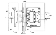
202 エミッタ部
203 レンズ
204 検出部
210 電気部品
400 コードストリップ光トラック
500 コードホイール光トラック
600 直交波形
Claims (6)
- エンコーダの1サイクルに対応する正弦波の1サイクルを伴って動くコード装置であって、前記コード装置に関連付けられた複数のパターンの厚さを、前記コード装置を通して正弦曲線の方式で変更し、
直交エンコーダ読取機を利用して前記コード装置をモニタし、前記正弦波の振幅を減少させることによって、ホーム振幅信号を生成する、
エンコーダのホーム位置を感知する方法。 - 前記コード装置は、複数の環状リングパターンと関連付けられたコードホイールを含む、請求項1に記載の方法。
- 前記コード装置は、複数の長手方向ラインパターンと関連付けられたコードストリップを含む、請求項1に記載の方法。
- 正弦波で変調された前記複数のパターンの厚さは、前記直交エンコーダ読取機の出力により歪みの少ない正弦波信号を生み、これにより、正確な位置補間及びホーム位置を示すデータを提供する、請求項1に記載の方法。
- 複数の環状リングパターンに関連付けられたコードホイールを含み、エンコーダの1サイクルに対応する正弦波の1サイクルを伴って動く、コード装置であって、コード装置に関連付けられた複数のパターンの厚さを、前記コード装置を通して正弦曲線の方式で変更し、
直交エンコーダ読取機を利用して前記コード装置をモニタし、前記正弦波の振幅を減少させることによって、ホーム振幅信号を生成する、
エンコーダのホーム位置を感知する方法。 - 複数のパターンと関連付けられ、前記複数のパターンの厚さを正弦曲線の方式で変更できると共に、エンコーダの1サイクルに対応する正弦波の1サイクルを伴って動く、コード装置と、
前記コード装置をモニタし、前記正弦波の振幅を減少させることによってホーム振幅信号を生成する、直交エンコーダ読取機と、
を備える、エンコーダのホーム位置を感知するシステム。
Applications Claiming Priority (2)
| Application Number | Priority Date | Filing Date | Title |
|---|---|---|---|
| US12/145,877 US7934657B2 (en) | 2008-06-25 | 2008-06-25 | Encoder home position sensing method and system |
| US12/145,877 | 2008-06-25 |
Publications (2)
| Publication Number | Publication Date |
|---|---|
| JP2010008415A true JP2010008415A (ja) | 2010-01-14 |
| JP5358313B2 JP5358313B2 (ja) | 2013-12-04 |
Family
ID=41446207
Family Applications (1)
| Application Number | Title | Priority Date | Filing Date |
|---|---|---|---|
| JP2009149508A Expired - Fee Related JP5358313B2 (ja) | 2008-06-25 | 2009-06-24 | エンコーダのホーム位置を感知する方法及びシステム |
Country Status (6)
| Country | Link |
|---|---|
| US (1) | US7934657B2 (ja) |
| JP (1) | JP5358313B2 (ja) |
| KR (1) | KR101506472B1 (ja) |
| CN (1) | CN101614559B (ja) |
| BR (1) | BRPI0901997A2 (ja) |
| MX (1) | MX2009006601A (ja) |
Cited By (3)
| Publication number | Priority date | Publication date | Assignee | Title |
|---|---|---|---|---|
| WO2013094818A1 (ko) * | 2011-12-23 | 2013-06-27 | 알에스오토메이션주식회사 | 광학 인코더 |
| JP2014130019A (ja) * | 2012-12-28 | 2014-07-10 | Canon Inc | スケール、変位検出装置、レンズ装置、撮像システム、および、組み立て装置 |
| CN106778992A (zh) * | 2016-11-19 | 2017-05-31 | 哈尔滨理工大学 | 基于圆周排列台阶阵列的信息解码方法 |
Families Citing this family (10)
| Publication number | Priority date | Publication date | Assignee | Title |
|---|---|---|---|---|
| JP5882590B2 (ja) | 2011-02-28 | 2016-03-09 | キヤノン株式会社 | 光学式エンコーダおよび光学式エンコーダを有する装置 |
| US9925394B2 (en) * | 2011-06-08 | 2018-03-27 | Varian Medical Systems, Inc. | Automatic health detection for motion axes in medical linear accelerators |
| US9211741B2 (en) * | 2012-07-17 | 2015-12-15 | Hewlett-Packard Development Company, L.P. | Position encoder systems |
| WO2015013823A1 (en) * | 2013-07-29 | 2015-02-05 | Ats Automation Tooling Systems Inc. | System and method for tracking a moving element in a conveyor system |
| US10352766B1 (en) * | 2014-12-10 | 2019-07-16 | Kla-Tencor Corporation | Focusing modules and methods |
| US20170174096A1 (en) * | 2015-12-17 | 2017-06-22 | Zack Z. Wang | Feedback for control of a wheel hub motor |
| JP2019018415A (ja) | 2017-07-13 | 2019-02-07 | キヤノン株式会社 | 記録装置及びその記録制御方法 |
| DE102018200449A1 (de) * | 2018-01-12 | 2019-07-18 | Dr. Johannes Heidenhain Gmbh | Positionsmesseinrichtung |
| CN109506900B (zh) * | 2018-11-05 | 2023-11-14 | 苏州工业职业技术学院 | 一种用于近红外相机的成像帧率检测系统及其检测方法 |
| CN116726415B (zh) * | 2023-08-14 | 2023-10-20 | 智维精准(北京)医疗科技有限公司 | 一种偏移补偿系统及直线加速器 |
Citations (5)
| Publication number | Priority date | Publication date | Assignee | Title |
|---|---|---|---|---|
| JPH10318790A (ja) * | 1997-04-09 | 1998-12-04 | Hewlett Packard Co <Hp> | 位置エンコーダ |
| JP2004219422A (ja) * | 2003-01-15 | 2004-08-05 | Xerox Corp | アナログ直交位相エンコーダから高品質の正弦曲線を求める方法および装置 |
| JP2005017297A (ja) * | 2003-06-26 | 2005-01-20 | Xerox Corp | 位置エンコーダの光学格子 |
| US20050156553A1 (en) * | 2004-01-20 | 2005-07-21 | Chun Young-Sun | Method and apparatus to process an analog encoder signal |
| JP2007047041A (ja) * | 2005-08-10 | 2007-02-22 | Canon Inc | 位置検出装置及び撮像装置 |
Family Cites Families (6)
| Publication number | Priority date | Publication date | Assignee | Title |
|---|---|---|---|---|
| JP2695623B2 (ja) * | 1994-11-25 | 1998-01-14 | 株式会社ミツトヨ | 光学式エンコーダ |
| JP3869991B2 (ja) * | 2000-01-31 | 2007-01-17 | アルプス電気株式会社 | 回転型エンコーダ、及びその製造方法 |
| US6972403B2 (en) * | 2003-06-26 | 2005-12-06 | Xerox Corporation | Position encoder |
| US7253395B2 (en) * | 2003-11-17 | 2007-08-07 | Gsi Group Corporation | Absolute encoder employing concatenated, multi-bit, interpolated sub-encoders |
| CN100439866C (zh) * | 2004-05-21 | 2008-12-03 | 株式会社安川电机 | 多转型绝对值编码器 |
| CN101336416B (zh) * | 2006-02-01 | 2010-08-11 | 富士通株式会社 | 奇偶生成电路、奇偶生成电路用构成电路、信息处理装置以及编码器 |
-
2008
- 2008-06-25 US US12/145,877 patent/US7934657B2/en not_active Expired - Fee Related
-
2009
- 2009-06-18 MX MX2009006601A patent/MX2009006601A/es active IP Right Grant
- 2009-06-24 KR KR1020090056308A patent/KR101506472B1/ko not_active IP Right Cessation
- 2009-06-24 BR BRPI0901997-9A patent/BRPI0901997A2/pt not_active IP Right Cessation
- 2009-06-24 JP JP2009149508A patent/JP5358313B2/ja not_active Expired - Fee Related
- 2009-06-24 CN CN200910150728.1A patent/CN101614559B/zh not_active Expired - Fee Related
Patent Citations (5)
| Publication number | Priority date | Publication date | Assignee | Title |
|---|---|---|---|---|
| JPH10318790A (ja) * | 1997-04-09 | 1998-12-04 | Hewlett Packard Co <Hp> | 位置エンコーダ |
| JP2004219422A (ja) * | 2003-01-15 | 2004-08-05 | Xerox Corp | アナログ直交位相エンコーダから高品質の正弦曲線を求める方法および装置 |
| JP2005017297A (ja) * | 2003-06-26 | 2005-01-20 | Xerox Corp | 位置エンコーダの光学格子 |
| US20050156553A1 (en) * | 2004-01-20 | 2005-07-21 | Chun Young-Sun | Method and apparatus to process an analog encoder signal |
| JP2007047041A (ja) * | 2005-08-10 | 2007-02-22 | Canon Inc | 位置検出装置及び撮像装置 |
Cited By (3)
| Publication number | Priority date | Publication date | Assignee | Title |
|---|---|---|---|---|
| WO2013094818A1 (ko) * | 2011-12-23 | 2013-06-27 | 알에스오토메이션주식회사 | 광학 인코더 |
| JP2014130019A (ja) * | 2012-12-28 | 2014-07-10 | Canon Inc | スケール、変位検出装置、レンズ装置、撮像システム、および、組み立て装置 |
| CN106778992A (zh) * | 2016-11-19 | 2017-05-31 | 哈尔滨理工大学 | 基于圆周排列台阶阵列的信息解码方法 |
Also Published As
| Publication number | Publication date |
|---|---|
| MX2009006601A (es) | 2010-01-18 |
| JP5358313B2 (ja) | 2013-12-04 |
| US7934657B2 (en) | 2011-05-03 |
| KR101506472B1 (ko) | 2015-03-27 |
| CN101614559A (zh) | 2009-12-30 |
| KR20100002157A (ko) | 2010-01-06 |
| CN101614559B (zh) | 2014-10-01 |
| BRPI0901997A2 (pt) | 2010-04-13 |
| US20090321520A1 (en) | 2009-12-31 |
Similar Documents
| Publication | Publication Date | Title |
|---|---|---|
| JP5358313B2 (ja) | エンコーダのホーム位置を感知する方法及びシステム | |
| US7304295B2 (en) | Method and system of detecting eccentricity and up/down movement of a code wheel of an optical encoder set | |
| US8525102B2 (en) | Optical encoding system and optical encoder having an array of incremental photodiodes and an index photodiode for use in an optical encoding system | |
| JP5063996B2 (ja) | 正弦波フォトディテクタ出力信号を有する光学エンコーダ | |
| JP5932285B2 (ja) | エンコーダおよびこれを備えた装置 | |
| EP2869032B1 (en) | Encoder, motor with encoder, and servo system | |
| EP3767243B1 (en) | Encoder, servo motor, and servo system | |
| JP2007078538A (ja) | モータ、回転制御装置、及び回転検出回路 | |
| US7834310B2 (en) | Position encoder's signal processing method and system | |
| JP2002039797A (ja) | エンコーダ | |
| JPH08166257A (ja) | ロータリーエンコーダとこのロータリーエンコーダに用いる回転ディスク | |
| JP2020091104A (ja) | アブソリュートロータリエンコーダ | |
| JP2013108911A (ja) | 光学式エンコーダおよびこれを備えた装置 | |
| US10914612B2 (en) | Indexed optical encoder | |
| JP2015094682A (ja) | エンコーダ、エンコーダを備えた装置、位置検出方法および位置検出処理プログラム | |
| JP2010085158A (ja) | 光電式エンコーダ、及び光電式エンコーダを用いたダブルエンコーダシステム | |
| JP2007241671A (ja) | ペン式バーコードスキャナー | |
| JPS61142469A (ja) | 回転体の回転方向および速度検出装置 | |
| JP2007210154A (ja) | 画像形成装置 |
Legal Events
| Date | Code | Title | Description |
|---|---|---|---|
| A621 | Written request for application examination |
Free format text: JAPANESE INTERMEDIATE CODE: A621 Effective date: 20120618 |
|
| A131 | Notification of reasons for refusal |
Free format text: JAPANESE INTERMEDIATE CODE: A131 Effective date: 20130507 |
|
| A521 | Request for written amendment filed |
Free format text: JAPANESE INTERMEDIATE CODE: A523 Effective date: 20130708 |
|
| TRDD | Decision of grant or rejection written | ||
| A01 | Written decision to grant a patent or to grant a registration (utility model) |
Free format text: JAPANESE INTERMEDIATE CODE: A01 Effective date: 20130806 |
|
| A61 | First payment of annual fees (during grant procedure) |
Free format text: JAPANESE INTERMEDIATE CODE: A61 Effective date: 20130902 |
|
| R150 | Certificate of patent or registration of utility model |
Ref document number: 5358313 Country of ref document: JP Free format text: JAPANESE INTERMEDIATE CODE: R150 Free format text: JAPANESE INTERMEDIATE CODE: R150 |
|
| R250 | Receipt of annual fees |
Free format text: JAPANESE INTERMEDIATE CODE: R250 |
|
| R250 | Receipt of annual fees |
Free format text: JAPANESE INTERMEDIATE CODE: R250 |
|
| R250 | Receipt of annual fees |
Free format text: JAPANESE INTERMEDIATE CODE: R250 |
|
| LAPS | Cancellation because of no payment of annual fees |