JP2010008020A - Heat exchanger - Google Patents
Heat exchanger Download PDFInfo
- Publication number
- JP2010008020A JP2010008020A JP2008170497A JP2008170497A JP2010008020A JP 2010008020 A JP2010008020 A JP 2010008020A JP 2008170497 A JP2008170497 A JP 2008170497A JP 2008170497 A JP2008170497 A JP 2008170497A JP 2010008020 A JP2010008020 A JP 2010008020A
- Authority
- JP
- Japan
- Prior art keywords
- plate
- tank body
- tank
- heat exchanger
- header
- Prior art date
- Legal status (The legal status is an assumption and is not a legal conclusion. Google has not performed a legal analysis and makes no representation as to the accuracy of the status listed.)
- Granted
Links
Images


Abstract
Description
この発明は、熱交換器に関し、さらに詳しくは、たとえばCO2などの超臨界冷媒が用いられる超臨界冷凍サイクルに使用される熱交換器に関する。 The present invention relates to a heat exchanger, and more particularly to a heat exchanger used in a supercritical refrigeration cycle in which a supercritical refrigerant such as CO 2 is used.
この明細書において、「超臨界冷凍サイクル」とは、高圧側において、冷媒が臨界圧力を超えた超臨界状態となる冷凍サイクルを意味するものとし、「超臨界冷媒」とは、超臨界冷凍サイクルに用いられる冷媒を意味するものとする。 In this specification, the “supercritical refrigeration cycle” means a refrigeration cycle in which the refrigerant reaches a supercritical state exceeding the critical pressure on the high-pressure side, and the “supercritical refrigerant” means the supercritical refrigeration cycle. It shall mean the refrigerant used in
たとえば、圧縮機、ガスクーラ、エバポレータ、減圧器、およびガスクーラから出てきた冷媒とエバポレータから出てきた冷媒とを熱交換させる中間熱交換器を備えた超臨界冷凍サイクルのガスクーラに用いられる熱交換器として、互いに間隔をおいて配置された1対のヘッダタンクと、両ヘッダタンク間に並列状に配置されかつ両端部がそれぞれ両ヘッダタンクに接続された複数の熱交換管と、ヘッダタンクに接合されたブラケットとを備えており、各ヘッダタンクが、タンク本体と、タンク本体における熱交換管側を向いた面を覆うとともにタンク本体に接合された管接続用プレートとにより構成され、タンク本体が、外側に位置する第1プレートと、第1プレートと管接続用プレートとの間に介在させられるとともに両プレートにろう付された第2プレートとよりなり、管接続用プレートの通風方向の両側縁部に、タンク本体側に突出し、タンク本体の通風方向の両側面の全体を覆う側面被覆壁が形成されるとともに、側面被覆壁の先端に第1プレート外面の通風方向の両側縁部に係合する係合壁が側面被覆壁の全長にわたって設けられ、ブラケットが、ヘッダタンクを通風方向の両側から挟持する挟持部を有しており、挟持部によりヘッダタンクを挟持した状態で、ブラケットがヘッダタンクに接合されている熱交換器が知られている(特許文献1参照)。 For example, a heat exchanger used in a gas cooler of a supercritical refrigeration cycle having a compressor, a gas cooler, an evaporator, a decompressor, and an intermediate heat exchanger that exchanges heat between the refrigerant that has come out of the gas cooler and the refrigerant that has come out of the evaporator A pair of header tanks arranged at a distance from each other, a plurality of heat exchange pipes arranged in parallel between both header tanks and connected to both header tanks at both ends, and joined to the header tank Each header tank is composed of a tank main body and a pipe connecting plate that covers the surface of the tank main body facing the heat exchange pipe and is joined to the tank main body. The first plate located outside, the first plate and the pipe connecting plate are interposed, and the two plates are brazed The side plate wall is formed on the both side edges of the pipe connection plate in the ventilation direction and protrudes toward the tank body and covers both sides of the tank body in the ventilation direction. Engagement walls that engage both side edges in the ventilation direction of the outer surface of the first plate are provided at the front end of the coating wall over the entire length of the side coating wall, and the bracket has a clamping part that clamps the header tank from both sides in the ventilation direction. In addition, there is known a heat exchanger in which a bracket is joined to a header tank in a state where the header tank is sandwiched by a sandwiching portion (see Patent Document 1).
ところで、特許文献1記載の熱交換器の製造は、各部品を組み立てて仮止めした後、各部品を一括してろう付することにより行われるが、各部品を組み立てて仮止めする際に、管接続用プレートの係合壁は、側面被覆壁に真っ直ぐに連なった係合壁形成部の状態となされており、タンク本体用の第1プレートおよび第2プレートと、管接続用プレートを重ね合わせた後、係合壁形成部が屈曲されて第1プレート外面の通風方向の両側縁部に係合する係合壁が形成されることにより3つのプレートが仮止めされる。また、各部品を組み立てて仮止めする際に、ブラケットは、上述した3つのプレートが仮止めされた後、挟持部により3つのプレートを両側から挟持することによりブラケットが仮止めされるようになっている。
By the way, manufacture of the heat exchanger described in
しかしながら、特許文献1記載の熱交換器においては、製造の際に、3つのプレートの仮止めと、ブラケットの仮止めを別の工程で行う必要があり、工程数が増えて製造コストが高くなるという問題がある。また、ブラケットの3つのプレートへの仮止めの際に、ブラケットが3つのプレートの長さ方向にずれるおそれがある。
この発明の目的は、上記問題を解決し、製造の際の工程数を減少することができるとともに、ブラケットの位置ずれを防止しうる熱交換器を提供することにある。 An object of the present invention is to provide a heat exchanger that can solve the above-described problems, reduce the number of manufacturing steps, and prevent the bracket from being displaced.
本発明は、上記目的を達成するために以下の態様からなる。 In order to achieve the above object, the present invention comprises the following aspects.
1)互いに間隔をおいて配置された1対のヘッダタンクと、両ヘッダタンク間に並列状に配置されかつ両端部がそれぞれ両ヘッダタンクに接続された複数の熱交換管と、ヘッダタンクに接合されたブラケットとを備えており、各ヘッダタンクが、タンク本体と、タンク本体における熱交換管側を向いた面を覆うとともにタンク本体に接合された管接続用プレートとにより構成され、管接続用プレートの通風方向の両側縁部に、タンク本体側に突出し、タンク本体の通風方向の両側面に沿う突出壁が形成されている熱交換器において、
タンク本体の通風方向の少なくとも一側縁部に、タンク本体の厚さ方向外面および通風方向両側面に開口し、かつタンク本体の厚さ方向にのびる凹溝が形成され、ブラケットにタンク本体の凹溝に嵌る爪が設けられ、ブラケットの爪がタンク本体の凹溝内に嵌め入れられるとともに、管接続用プレートの突出壁により通風方向内側に押さえられた状態で、ブラケットがヘッダタンクに接合されている熱交換器。
1) A pair of header tanks spaced from each other, a plurality of heat exchange pipes arranged in parallel between both header tanks and having both ends connected to both header tanks, and joined to the header tank Each header tank is composed of a tank main body and a pipe connecting plate that covers the surface of the tank main body facing the heat exchange pipe and is joined to the tank main body. In the heat exchanger in which the protruding wall along the both sides of the airflow direction of the tank body is formed on both side edges in the airflow direction of the plate,
At least one side edge in the ventilation direction of the tank body is formed with a groove that opens on the outer surface in the thickness direction of the tank body and on both sides of the ventilation direction and extends in the thickness direction of the tank body. A claw that fits into the groove is provided, the claw of the bracket is fitted into the recessed groove of the tank body, and the bracket is joined to the header tank while being pressed inward by the protruding wall of the pipe connection plate. Heat exchanger.
2)タンク本体の凹溝およびブラケットの爪が、それぞれ通風方向の両側部分に設けられている上記1)記載の熱交換器。 2) The heat exchanger according to 1) above, wherein the groove of the tank body and the claws of the bracket are provided on both side portions in the ventilation direction.
3)タンク本体の凹溝が、隣り合う熱交換管どうしの間に形成されている上記1)または2)記載の熱交換器。 3) The heat exchanger according to 1) or 2) above, wherein the concave groove of the tank body is formed between adjacent heat exchange tubes.
4)タンク本体の凹溝が、タンク本体の厚さ方向外面から同内面までのびている上記1)〜3)のうちのいずれかに記載の熱交換器。 4) The heat exchanger according to any one of 1) to 3) above, wherein the concave groove of the tank body extends from the outer surface in the thickness direction of the tank body to the inner surface.
5)管接続用プレートの突出壁がタンク本体の通風方向の両側面の全体を覆っており、突出壁の突出端縁に、通風方向内方に突出し、かつタンク本体の外面に係合する係合爪が形成され、係合爪がタンク本体外面に接合されている上記1)〜4)のうちのいずれかに記載の熱交換器。 5) The projecting wall of the pipe connecting plate covers the entire sides of the tank body in the ventilation direction. The projecting wall protrudes inward in the ventilation direction at the projecting edge of the projecting wall and engages with the outer surface of the tank body. The heat exchanger according to any one of 1) to 4) above, wherein a joint claw is formed and the engagement claw is joined to the outer surface of the tank body.
6)タンク本体が、外側に位置する第1プレートと、第1プレートと管接続用プレートとの間に介在させられるとともに両プレートにろう付された第2プレートとよりなり、凹溝が第1プレートから第2プレートにかけて形成されている上記1)〜5)のうちのいずれかに記載の熱交換器。 6) The tank body is composed of a first plate located outside, a second plate interposed between the first plate and the pipe connection plate and brazed to both plates, and the concave groove is the first. The heat exchanger according to any one of 1) to 5), which is formed from the plate to the second plate.
上記1)の熱交換器によれば、タンク本体の通風方向の少なくとも一側縁部に、タンク本体の厚さ方向外面および通風方向両側面に開口し、かつタンク本体の厚さ方向にのびる凹溝が形成され、ブラケットにタンク本体の凹溝に嵌る爪が設けられ、ブラケットの爪がタンク本体の凹溝内に嵌め入れられるとともに、管接続用プレートの突出壁により通風方向内側に押さえられた状態で、ブラケットがヘッダタンクに接合されているので、製造時に各部品を組み立てて仮止めする際に、ブラケットの爪を凹溝内に嵌め入れた後、管接続用プレートの突出壁を両側から通風方向の内側に押圧することにより、管接続用プレートをタンク本体に仮止めすることが可能になるとともに、ブラケットをタンク本体および管接続用プレートに仮止めすることが可能になる。したがって、製造時の工程数を減少することができる。また、ブラケットの爪がタンク本体の凹溝内に嵌め入れられた状態で、ブラケットがタンク本体および管接続用プレートに仮止めされるので、ブラケットのタンク本体の長さ方向への位置ずれが防止される。 According to the heat exchanger of 1) above, at least one side edge in the ventilation direction of the tank body is open to the outer surface in the thickness direction of the tank body and both sides in the ventilation direction and extends in the thickness direction of the tank body. A groove is formed, and a claw that fits into the groove of the tank body is provided on the bracket. The claw of the bracket is fitted into the groove of the tank body, and is held inward in the ventilation direction by the protruding wall of the pipe connection plate Since the bracket is joined to the header tank in the state, when assembling and temporarily fixing each part during manufacturing, after inserting the claws of the bracket into the concave groove, the protruding wall of the pipe connection plate is By pressing inward in the ventilation direction, the pipe connection plate can be temporarily fixed to the tank body, and the bracket is temporarily fixed to the tank main body and the pipe connection plate. Possible to become. Therefore, the number of processes during manufacturing can be reduced. In addition, the bracket is temporarily fixed to the tank body and pipe connection plate with the bracket's pawl fitted in the groove in the tank body, preventing the bracket from shifting in the length direction of the tank body. Is done.
上記2)の熱交換器によれば、タンク本体の凹溝およびブラケットの爪が、それぞれ通風方向の両側部分に設けられているので、製造時のブラケットのタンク本体および管接続用プレートへの仮止めが強固に行われる。 According to the heat exchanger of 2) above, the groove of the tank main body and the claws of the bracket are provided on both sides in the ventilation direction, so that the temporary attachment of the bracket to the tank main body and the pipe connection plate at the time of manufacture is possible. The stop is made firmly.
上記3)の熱交換器によれば、タンク本体の凹溝が、隣り合う熱交換管どうしの間に形成されているので、ヘッダタンクの耐圧性の低下が防止される。すなわち、上記1)の熱交換器においては、通常、管接続用プレートにおけるヘッダタンクの冷媒流路と対応する部分に、複数の管挿入穴が管接続用プレートの長さ方向に間隔をおいて貫通状に形成されるとともに、熱交換管の端部が管挿入穴に挿入されて管接続用プレートにろう付され、タンク本体に管接続用プレートの管挿入穴をヘッダ部の冷媒流路内に通じさせる連通穴が形成されるので、熱交換管と対応する位置にタンク本体の凹溝が形成されていると、タンク本体と管接続用プレートとの接合面積が減少して耐圧性が低下する。 According to the heat exchanger of the above 3), since the concave groove of the tank body is formed between the adjacent heat exchange pipes, the pressure resistance of the header tank is prevented from being lowered. That is, in the heat exchanger of 1) above, a plurality of tube insertion holes are usually spaced apart in the length direction of the pipe connection plate in the portion corresponding to the refrigerant flow path of the header tank in the pipe connection plate. The end of the heat exchange pipe is inserted into the pipe insertion hole and brazed to the pipe connection plate, and the pipe insertion hole of the pipe connection plate is connected to the tank body in the refrigerant flow path of the header section. As a communication hole is formed to communicate with the heat exchange pipe, if the tank main body has a concave groove at a position corresponding to the heat exchange pipe, the joint area between the tank main body and the pipe connection plate is reduced, and the pressure resistance is reduced. To do.
上記5)の熱交換器によれば、製造時のタンク本体と管接続用プレートとの仮止めの際には、係合爪を突出壁に真っ直ぐに連なった係合爪形成用突片の状態としておき、タンク本体と管接続用プレートとを組み合わせた後に係合爪形成用突片を通風方向内側に曲げることにより、タンク本体と管接続用プレートとを仮止めすることができるので、両者の仮止めを強固に行うことができる。しかも、係合爪形成用突片の通風方向内側への曲げは、管接続用プレートの突出壁を両側から通風方向の内側に押圧するのと同時に行うことができる。 According to the heat exchanger of 5) above, when the tank main body and the pipe connection plate are temporarily fixed at the time of manufacture, the state of the engaging claw forming protruding piece in which the engaging claw is straightly connected to the protruding wall. The tank body and the pipe connection plate can be temporarily fixed by bending the engagement claw-forming projection piece inward in the airflow direction after combining the tank body and the pipe connection plate. Temporary fixing can be performed firmly. Moreover, the bending of the engaging claw-forming projecting piece inward in the ventilation direction can be performed simultaneously with pressing the protruding walls of the pipe connection plate inward in the ventilation direction from both sides.
以下、この発明の実施形態を、図面を参照して説明する。この実施形態は、この発明による熱交換器を、超臨界冷凍サイクルのガスクーラに適用したものである。 Embodiments of the present invention will be described below with reference to the drawings. In this embodiment, the heat exchanger according to the present invention is applied to a gas cooler of a supercritical refrigeration cycle.
なお、以下の説明において、通風方向下流側(図1に矢印Xで示す方向)を前、これと反対側を後というものとし、図1および図2の上下、左右をそれぞれ上下、左右というものとする。 In the following description, the downstream side in the ventilation direction (the direction indicated by the arrow X in FIG. 1) is referred to as the front, the opposite side is referred to as the rear, and the upper and lower sides and the left and right sides in FIGS. And
さらに、以下の説明において、「アルミニウム」という用語には、純アルミニウムの他にアルミニウム合金を含むものとする。 Furthermore, in the following description, the term “aluminum” includes aluminum alloys in addition to pure aluminum.
図1および図2はこの発明による熱交換器を適用したガスクーラの全体構成を示し、図3はその要部の構成を示す。また、図4はガスクーラを製造する方法の一部の工程を示す。 1 and 2 show the overall configuration of a gas cooler to which a heat exchanger according to the present invention is applied, and FIG. 3 shows the configuration of the main part thereof. FIG. 4 shows some steps of the method of manufacturing the gas cooler.
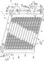
図1〜図3において、超臨界冷媒、たとえばCO2を使用する超臨界冷凍サイクルのガスクーラ(1)は、左右方向に間隔をおいて配置されかつ上下方向にのびる2つのヘッダタンク(2)(3)と、両ヘッダタンク(2)(3)間に、上下方向に間隔をおくとともに幅方向を前後方向に向けて配置された複数の扁平状熱交換管(4)と、隣接する熱交換管(4)どうしの間の通風間隙、および上下両端の熱交換管(4)の外側に配置されて熱交換管(4)にろう付されたコルゲートフィン(5)と、上下両端のコルゲートフィン(5)の外側にそれぞれ配置されてコルゲートフィン(5)にろう付されたアルミニウム製サイドプレート(6)と、各ヘッダタンク(2)(3)にろう付されかつガスクーラ(1)を車両に取り付けるのに用いられるブラケット(7)とを備えている。なお、この実施形態において、右側のヘッダタンク(2)を第1ヘッダタンク、左側のヘッダタンク(3)を第2ヘッダタンクというものとする。 1 to 3, a gas cooler (1) of a supercritical refrigeration cycle using a supercritical refrigerant, for example, CO 2 , has two header tanks (2) (2) ( 3) and a plurality of flat heat exchange pipes (4) arranged between the header tanks (2) and (3) in the vertical direction and with the width direction oriented in the front-rear direction, and adjacent heat exchange Corrugated fins (5) disposed outside the heat exchange tubes (4) at the upper and lower ends and brazed to the heat exchange tubes (4), and corrugated fins at the upper and lower ends. The aluminum side plate (6), which is placed outside (5) and brazed to the corrugated fin (5), and brazed to each header tank (2) (3) and the gas cooler (1) to the vehicle And a bracket (7) used for mounting. In this embodiment, the right header tank (2) is referred to as a first header tank, and the left header tank (3) is referred to as a second header tank.
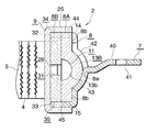
第1ヘッダタンク(2)は、アルミニウム製タンク本体(8)と、両面にろう材層を有するブレージングシート、ここではアルミニウムブレージングシートから形成され、かつタンク本体(8)の左側面を覆うようにタンク本体(8)にろう付された管接続用プレート(9)とを備えており、内部が冷媒流路(13a)となった入口ヘッダ部(13A)および内部が冷媒流路(13b)となった出口ヘッダ部(13B)が上下に並んで設けられている。 The first header tank (2) is formed of an aluminum tank body (8) and a brazing sheet having a brazing filler metal layer on both sides, here an aluminum brazing sheet, and covers the left side surface of the tank body (8). A pipe connection plate (9) brazed to the tank body (8), and an inlet header portion (13A) whose inside is a refrigerant flow path (13a) and a refrigerant flow path (13b) inside. The exit header portions (13B) thus formed are provided side by side.
タンク本体(8)は、両面にろう材層を有するブレージングシート、ここではアルミニウムブレージングシートから形成され、かつ右側(外側)に配置された第1プレート(8A)と、金属ベア材、ここではアルミニウムベア材からなり、かつ第1プレート(8A)と管接続用プレート(9)との間に介在させられて両プレート(8A)(9)にろう付された第2プレート(8B)とにより構成されている。第1プレート(8A)の前後方向の中央部に、左側(第2プレート(8B)側)に開口した横断面略U字状の外方屈曲部(8a)が全長にわたって形成されており、外方屈曲部(8a)の左側を向いた開口は第2プレート(8B)により塞がれている。また、第1プレート(8A)の外方屈曲部(8a)の前後両側部分はそれぞれ同一平面内に位置する平坦部(8b)となっている。タンク本体(8)の上下両端部および上下方向の中央部に、第1プレート(8A)の外方屈曲部(8a)内の上下方向にのびかつ上下両端が開口した内部空間(11)を塞ぐ仕切板(12)が、両プレート(8A)(8B)に跨って配置されている。そして、内部空間(11)の上下両端開口が仕切板(12)により閉鎖されるとともに、内部空間(11)が上下方向の中央部において仕切板(12)により上下両側部分(11A)(11B)に区画されている。 The tank body (8) is composed of a brazing sheet having a brazing filler metal layer on both sides, here an aluminum brazing sheet, and disposed on the right side (outside) and a metal plate, here aluminum. Consists of a second plate (8B) made of bare material and interposed between the first plate (8A) and the pipe connection plate (9) and brazed to both plates (8A) (9) Has been. An outwardly bent portion (8a) having a substantially U-shaped cross section that opens to the left side (second plate (8B) side) is formed at the center in the front-rear direction of the first plate (8A). The opening facing the left side of the fold portion (8a) is closed by the second plate (8B). The front and rear side portions of the outward bent portion (8a) of the first plate (8A) are flat portions (8b) located in the same plane. The upper and lower ends of the tank body (8) and the center of the upper and lower direction are filled with an internal space (11) extending in the vertical direction in the outward bent portion (8a) of the first plate (8A) and open at both upper and lower ends. A partition plate (12) is disposed across both plates (8A) and (8B). The upper and lower end openings of the internal space (11) are closed by the partition plate (12), and the internal space (11) is vertically separated by the partition plate (12) at the upper and lower sides (11A) (11B). It is divided into.
第1プレート(8A)の前側縁部における上下方向の中央部よりも若干下方の部分に、全厚にわたる2つの切り欠き(14)が上下方向に間隔をおいて形成されている。また、第1プレート(8A)の後側縁部における上下方向の中央部よりも若干下方の部分で、かつ前側縁部の2つの切り欠き(14)間の部分に、全厚にわたる1つの切り欠き(15)が形成されている。さらに、第1プレート(8A)の上下両端部および上下方向の中央部に、それぞれ前後方向に長くかつ一方の平坦部(8b)から他方の平坦部(8b)に至る貫通穴(16)が形成されている。 Two notches (14) extending over the entire thickness are formed at intervals in the vertical direction at a portion slightly lower than the central portion in the vertical direction at the front edge of the first plate (8A). In addition, one notch extending over the entire thickness is formed in a portion slightly lower than the central portion in the vertical direction on the rear edge of the first plate (8A) and between the two notches (14) on the front edge. A notch (15) is formed. Furthermore, through holes (16) that are long in the front-rear direction and extend from one flat part (8b) to the other flat part (8b) are formed in the upper and lower end parts and the vertical center part of the first plate (8A). Has been.
第1プレート(8A)の外方屈曲部(8a)の頂部における上端部の貫通穴(16)よりも若干下方の位置に冷媒入口(17)が形成されており、第1プレート(8A)の外面に、冷媒入口(17)に通じる冷媒流入路(19)を有する金属製、ここではアルミニウムベア材製の直方体状入口部材(18)が、第1プレート(8A)外面のろう材を利用してろう付されている。また、外方屈曲部(8a)の頂部における下端部の貫通穴(16)よりも若干上方の位置に冷媒出口(21)が形成されており、第1プレート(8A)の外面に、冷媒出口(21)に通じる冷媒流出路(23)を有する金属製、ここではアルミニウムベア材製の直方体状出口部材(22)が、第1プレート(8A)外面のろう材を利用してろう付されている。第1プレート(8A)は、両面にろう材層を有するアルミニウムブレージングシートにプレス加工を施することにより形成されている。 A refrigerant inlet (17) is formed at a position slightly below the through hole (16) at the upper end of the top of the outward bent portion (8a) of the first plate (8A), and the first plate (8A) A rectangular parallelepiped inlet member (18) made of a metal, here an aluminum bare material, having a refrigerant inflow passage (19) leading to the refrigerant inlet (17) uses a brazing material on the outer surface of the first plate (8A). It is brazed. Further, a refrigerant outlet (21) is formed at a position slightly above the through hole (16) at the lower end at the top of the outward bent portion (8a), and the refrigerant outlet is formed on the outer surface of the first plate (8A). A rectangular parallelepiped outlet member (22) made of metal having a refrigerant outflow path (23) leading to (21), here made of aluminum bare material, is brazed using a brazing material on the outer surface of the first plate (8A). Yes. The first plate (8A) is formed by pressing an aluminum brazing sheet having a brazing filler metal layer on both sides.
第1ヘッダタンク(2)の管接続用プレート(9)には、前後方向に長い複数の貫通状管挿入穴(24)が、上下方向に間隔をおいて形成されている。上半部の複数の管挿入穴(24)は、タンク本体(8)の第1プレート(8A)の内部空間(11)における上側部分(11A)の上下方向の範囲内に形成され、同じく下半部の複数の管挿入穴(24)は、タンク本体(8)の第1プレート(8A)の内部空間(11)における下側部分(11B)の上下方向の範囲内に形成されている。管挿入穴(24)の前後方向の長さは、外方屈曲部(8a)の前後方向の幅よりも若干長く、管挿入穴(24)の前後両端部は外方屈曲部(8a)の前後両側縁よりも外方に突出している。さらに、管接続用プレート(9)の前後両側縁部に、それぞれ右方に突出して先端が第1プレート(8A)の外面まで至り、かつタンク本体(8)、すなわち第1プレート(8A)および第2プレート(8B)の前後両側面の全体を覆う突出壁(25)が一体に形成され、第1プレート(8A)および第2プレート(8B)の前後両側面にろう付されている。各突出壁(25)の突出端縁の上下両端部および上下方向中央部、すなわち各貫通穴(16)と対応する位置に、それぞれ前後方向内方に突出しかつ外側プレート(8)の外面に係合する係合爪(26)が一体に形成され、係合爪(26)が外側プレート(8)にろう付されている。係合爪(26)は、外側プレート(8)の貫通穴(16)の前後両端部を覆っている。なお、図4に実線で示すように、係合爪(26)は、3つのプレート(8A)(8B)(9)を組み合わせる前の状態では、突出壁(25)に真っ直ぐに連なって左右方向外方にのびている。真っ直ぐな係合爪形成用突片を(26A)で示す。管接続用プレート(9)は、両面にろう材層を有するアルミニウムブレージングシートにプレス加工を施すことにより形成されている。 In the pipe connection plate (9) of the first header tank (2), a plurality of penetrating pipe insertion holes (24) elongated in the front-rear direction are formed at intervals in the vertical direction. A plurality of tube insertion holes (24) in the upper half are formed in the vertical range of the upper portion (11A) in the internal space (11) of the first plate (8A) of the tank body (8), and The plurality of pipe insertion holes (24) in the half are formed in the vertical range of the lower part (11B) in the internal space (11) of the first plate (8A) of the tank body (8). The length in the front-rear direction of the tube insertion hole (24) is slightly longer than the width in the front-rear direction of the outward bent portion (8a), and both front and rear ends of the tube insertion hole (24) are formed in the outer bent portion (8a). Projects outward from both front and rear edges. Furthermore, the pipe connecting plate (9) protrudes to the right and left sides of the front and back, and the tip reaches the outer surface of the first plate (8A), and the tank body (8), that is, the first plate (8A) and Projecting walls (25) that cover the entire front and rear side surfaces of the second plate (8B) are integrally formed and brazed to the front and rear side surfaces of the first plate (8A) and the second plate (8B). Projecting edges of each projecting wall (25) are projected inward in the front-rear direction and on the outer surface of the outer plate (8) at the upper and lower ends and the center in the vertical direction of the projecting edge, that is, in the positions corresponding to the through holes (16). A mating engagement claw (26) is integrally formed, and the engagement claw (26) is brazed to the outer plate (8). The engaging claw (26) covers both front and rear ends of the through hole (16) of the outer plate (8). As shown by the solid line in FIG. 4, the engaging claw (26) is connected straight to the protruding wall (25) in the left-right direction before the three plates (8A) (8B) (9) are combined. It extends outward. A straight engaging claw-forming projecting piece is indicated by (26A). The pipe connection plate (9) is formed by pressing an aluminum brazing sheet having a brazing filler metal layer on both sides.
第1ヘッダタンク(2)のタンク本体(8)の第2プレート(8B)には、前後方向に長くかつ管接続用プレート(9)の管挿入穴(24)をタンク本体(8)の第1プレート(8A)の内部空間(11)の上下両側部分(11A)(11B)内に通じさせる複数の連通穴(27)が貫通状に形成されている。各連通穴(27)は管挿入穴(24)よりも一回り大きくなっている。また、内部空間(11)の上側部分(11A)内に通じるすべての連通穴(27)は、それぞれ第2プレート(8B)における隣り合う連通穴(27)間の部分の前後方向中央部を切除することにより形成された連通部(28)により連通させられており、上側部分(11A)内に通じるすべての連通穴(27)の前後方向中央部、およびこれらの連通穴(27)を連通させる連通部(28)によって、第2プレート(8B)に、冷媒が上下方向に流れる冷媒流通部(29)が形成されている。また、内部空間(11)の下側部分(11B)内に通じるすべての連通穴(27)は、それぞれ第2プレート(8B)における隣り合う連通穴(27)間の部分の前後方向中央部を切除することにより形成された連通部(28)により連通させられており、下側部分(11B)内に通じるすべての連通穴(27)の前後方向中央部、およびこれらの連通穴(27)を連通させる連通部(28)によって、第2プレート(8B)に、冷媒が上下方向に流れる冷媒流通部(31)が形成されている。 The second plate (8B) of the tank body (8) of the first header tank (2) is long in the front-rear direction and has a pipe insertion hole (24) of the pipe connection plate (9). A plurality of communication holes (27) communicating with the upper and lower side portions (11A) (11B) of the internal space (11) of one plate (8A) are formed in a penetrating manner. Each communication hole (27) is slightly larger than the tube insertion hole (24). In addition, all the communication holes (27) leading into the upper part (11A) of the internal space (11) are cut off in the front-rear direction center of the part between the adjacent communication holes (27) in the second plate (8B). The communication part (28) formed by the communication is made, and the center part in the front-rear direction of all the communication holes (27) communicating with the upper part (11A) and the communication holes (27) are communicated. The communication part (28) forms a refrigerant circulation part (29) through which the refrigerant flows in the vertical direction on the second plate (8B). In addition, all the communication holes (27) communicating with the lower part (11B) of the internal space (11) are respectively located in the center in the front-rear direction of the part between the adjacent communication holes (27) in the second plate (8B). The communicating part (28) formed by excision communicates with the central part in the front-rear direction of all the communicating holes (27) communicating with the lower part (11B), and these communicating holes (27). The communication part (28) for communication forms a refrigerant circulation part (31) through which the refrigerant flows in the vertical direction on the second plate (8B).
第1ヘッダタンク(2)のタンク本体(8)の第2プレート(8B)の前後両側縁部における第1プレート(8A)の各切り欠き(14)(15)と対応する位置に、それぞれ全厚にわたる切り欠き(32)(33)が形成されている。そして、第1プレート(8A)の切り欠き(14)(15)と、第2プレート(8B)の切り欠き(32)(33)とによって、タンク本体(8)の前後両側縁部に、タンク本体(8)の左右方向外面(厚さ方向外面)および前後両側面(通風方向両側面)に開口し、かつ左右方向(タンク本体(8)の厚さ方向)にのびる凹溝(34)(35)が形成されている。 At the positions corresponding to the notches (14) and (15) of the first plate (8A) at the front and rear side edges of the second plate (8B) of the tank body (8) of the first header tank (2), Notches (32) and (33) extending through the thickness are formed. Then, the tank plate (8) has the notches (14) and (15) and the notches (32) and (33) of the second plate (8B) at the front and rear side edges of the tank body (8). Groove (34) (34) (opening in the left and right outer surface (thickness direction outer surface) and both front and rear side surfaces (ventilation direction both sides) and extending in the left and right direction (thickness direction of the tank body (8)) 35) is formed.
タンク本体(8)の第2プレート(8B)の上下両端部および上下方向の中央部に、第1プレート(8A)の貫通穴(16)と対応するように、それぞれ前後方向に長くかつ貫通穴(16)と同一の幅および長さを有する貫通穴(36)が形成されている。第1プレート(8A)の貫通穴(16)と第2プレート(8B)の貫通穴(36)とによって、タンク本体(8)に、貫通状の仕切板挿入穴(37)が両プレート(8A)(8B)に跨るように形成されている。各仕切板挿入穴(37)内に仕切板(12)が挿入されることによって、タンク本体(8)の第1プレート(8A)および第2プレート(8B)の上下両端部および上下方向の中央部に仕切板(12)が配置されている。 The tank body (8) is long and through-holes in the front-rear direction so as to correspond to the through-holes (16) of the first plate (8A) at the upper and lower ends of the second plate (8B) and the center in the vertical direction. A through hole (36) having the same width and length as (16) is formed. Through the through hole (16) of the first plate (8A) and the through hole (36) of the second plate (8B), a penetrating partition plate insertion hole (37) is formed in both plates (8A) on the tank body (8). ) (8B). By inserting the partition plate (12) into each partition plate insertion hole (37), the upper and lower ends of the first plate (8A) and the second plate (8B) of the tank body (8) and the center in the vertical direction. A partition plate (12) is disposed in the part.
仕切板(12)は両面にろう材層を有するアルミニウムブレージングシートにより形成されたものであって、仕切板挿入穴(37)内に、外側縁部が第1プレート(8A)の外面と面一となるように挿入され、この状態で、仕切板(12)の前後両側縁部が第1プレート(8A)および第2プレート(8B)にろう付され、同じく左右方向内側縁部が管接続用プレート(9)にろう付され、仕切板(12)の上下両面が第1プレート(8A)および第2プレート(8B)にろう付されている。 The partition plate (12) is formed of an aluminum brazing sheet having a brazing filler metal layer on both sides, and the outer edge is flush with the outer surface of the first plate (8A) in the partition plate insertion hole (37). In this state, the front and rear side edges of the partition plate (12) are brazed to the first plate (8A) and the second plate (8B), and the left and right inner edges are for pipe connection. The plate (9) is brazed, and the upper and lower surfaces of the partition plate (12) are brazed to the first plate (8A) and the second plate (8B).
第1ヘッダタンク(2)の入口ヘッダ部(13A)は、タンク本体(8)および管接続用プレート(9)、すなわち第1プレート(8A)、第2プレート(8B)および管接続用プレート(9)における上下方向中央部の仕切板(12)よりも上側の部分により形成され、同じく出口ヘッダ部(13B)は、タンク本体(8)および管接続用プレート(9)、すなわち第1プレート(8A)、第2プレート(8B)および管接続用プレート(9)における上下方向中央部の仕切板(12)よりも下側の部分により形成されている。第1ヘッダタンク(2)の入口ヘッダ部(13A)および出口ヘッダ部(13B)の冷媒流路(13a)(13b)は、第1プレート(8A)の内部空間(11)の上下両側部分(11A)(11B)と、第2プレート(8B)の上下の冷媒流通部(29)(31)とからなる。 The inlet header portion (13A) of the first header tank (2) includes a tank body (8) and a pipe connection plate (9), that is, a first plate (8A), a second plate (8B), and a pipe connection plate ( 9), the outlet header (13B) is formed by a portion above the partition plate (12) at the center in the vertical direction. Similarly, the outlet header (13B) has the tank body (8) and the pipe connection plate (9), that is, the first plate ( 8A), the second plate (8B), and the pipe connection plate (9) are formed by portions below the partition plate (12) at the center in the vertical direction. The refrigerant flow paths (13a) and (13b) of the inlet header portion (13A) and the outlet header portion (13B) of the first header tank (2) are the upper and lower side portions of the internal space (11) of the first plate (8A) ( 11A) (11B) and upper and lower refrigerant circulation portions (29), (31) of the second plate (8B).
ブラケット(7)は、第1プレート(8A)の外方屈曲部(8a)の前後方向中央部から右方に伸びかつガスクーラ(1)を車体に取り付けるためのボルト、ねじなどの締結具を通す貫通穴(41)があけられた取付本体部(40)と、取付本体部(40)の左側縁部の上下両端部に一体に形成され、かつ第1プレート(8A)外面の前側半部にろう付された2つの第1ベース部(42)と、取付本体部(40)の左側縁部における上下の第1ベース部(42)間に一体に形成され、かつ第1プレート(8A)外面の後側半部にろう付された1つの第2ベース部(43)とよりなる。各第1ベース部(42)は、第1プレート(8A)の外方屈曲部(8a)の前半部および前側平坦部(8b)の外面にろう付され、第2ベース部(43)は、第1プレート(8A)の外方屈曲部(8a)の後半部および後側平坦部(8b)の外面にろう付されている。ブラケット(7)の各第1ベース部(42)の前端部に、タンク本体(8)の前側の凹溝(34)内に嵌め入れられる爪(44)が一体に形成されている。ブラケット(7)の第2ベース部(43)の前端部の上下方向の中央部に、タンク本体(8)の後側の凹溝(35)内に嵌め入れられる爪(45)が一体に形成されている。各爪(44)(45)は、管接続用プレート(9)の突出壁(25)により前後方向外側から前後方向内側に押さえられた状態で、第1プレート(8A)、第2プレート(8B)および管接続用プレート(9)にろう付されている。 The bracket (7) extends rightward from the front-rear center of the outward bent portion (8a) of the first plate (8A) and passes fasteners such as bolts and screws for attaching the gas cooler (1) to the vehicle body. The mounting main body (40) with a through hole (41) and the upper and lower ends of the left side edge of the mounting main body (40) are formed integrally with the front half of the outer surface of the first plate (8A). An outer surface of the first plate (8A) formed integrally between the two first base parts (42) brazed and the upper and lower first base parts (42) at the left edge of the mounting body part (40). It consists of one second base part (43) brazed to the rear half part. Each first base part (42) is brazed to the outer surface of the front half part and the front flat part (8b) of the outward bent part (8a) of the first plate (8A), and the second base part (43) is The first plate (8A) is brazed to the outer surface of the rear half portion and the rear flat portion (8b) of the outward bent portion (8a). At the front end of each first base portion (42) of the bracket (7), a claw (44) that fits into the groove (34) on the front side of the tank body (8) is integrally formed. A claw (45) that fits into the groove (35) on the rear side of the tank body (8) is integrally formed at the center of the front end of the second base part (43) of the bracket (7). Has been. Each claw (44) (45) is pressed from the front-rear direction outer side to the front-rear direction inner side by the protruding wall (25) of the pipe connection plate (9), and the first plate (8A), the second plate (8B) ) And the pipe connecting plate (9).
図2に示すように、第2ヘッダタンク(3)は、第1ヘッダタンク(2)とほぼ同様な構成であり、同一物および同一部分に同一符号を付す。両ヘッダタンク(2)(3)は、管接続用プレート(9)どうしが対向するように配置されている。 As shown in FIG. 2, the second header tank (3) has substantially the same configuration as the first header tank (2), and the same components and the same parts are denoted by the same reference numerals. Both header tanks (2) and (3) are arranged so that the pipe connection plates (9) face each other.
第2ヘッダタンク(3)の第1プレート(8A)および第2プレート(8B)には上下両端部のみに仕切板(12)が配置されており、タンク本体(8)の第1プレート(8A)の内部空間(11)は、上下両端開口のみが仕切板(12)により閉鎖され、上下には区画されていない。また、第2ヘッダタンク(3)の管接続用プレート(9)のすべての管挿入穴(24)は、第1プレート(8A)の内部空間(11)の上下の範囲内に形成されており、管接続用プレート(9)のすべての管挿入穴(24)は、第2プレート(8B)のすべての連通穴(27)を介して、タンク本体(8)の第1プレート(8A)の内部空間(11)内に通じさせられている。第2プレート(8B)のすべての連通穴(27)は、第2プレート(8B)における隣り合う連通穴(27)間の部分の前後方向中央部を切除することにより形成された連通部(28)により連通させられている。その結果、連通部(28)、および連通穴(27)の前後方向中央部によって、第2プレート(8B)に冷媒が上下方向に流れる冷媒流通部(46)が形成されている。したがって、第2ヘッダタンク(3)には、第1ヘッダタンク(2)の入口ヘッダ部(13A)および出口ヘッダ部(13B)に跨るように、内部が冷媒流路(47a)となった1つの中間ヘッダ部(47)が形成されている。第2ヘッダタンク(3)の中間ヘッダ部(47)は、第1プレート(8A)、管接続用プレート(9)および第2プレート(8B)の全体により形成されている。中間ヘッダ部(47)の冷媒流路(47a)は、タンク本体(8)の第1プレート(8A)の内部空間(11)における上下両端の仕切板(12)間の部分と、第2プレート(8B)の冷媒流通部(46)とからなる。 The first plate (8A) and the second plate (8B) of the second header tank (3) are provided with partition plates (12) only at both upper and lower ends, and the first plate (8A) of the tank body (8). In the internal space (11), only the upper and lower end openings are closed by the partition plate (12) and are not partitioned vertically. In addition, all the pipe insertion holes (24) of the pipe connection plate (9) of the second header tank (3) are formed within the upper and lower ranges of the internal space (11) of the first plate (8A). , All pipe insertion holes (24) of the pipe connection plate (9) are connected to the first plate (8A) of the tank body (8) through all the communication holes (27) of the second plate (8B). It is made to communicate in the internal space (11). All the communication holes (27) of the second plate (8B) are formed by cutting the central part in the front-rear direction of the portion between the adjacent communication holes (27) in the second plate (8B) (28 ). As a result, a refrigerant flow part (46) through which the refrigerant flows in the vertical direction is formed in the second plate (8B) by the communication part (28) and the center part in the front-rear direction of the communication hole (27). Therefore, the inside of the second header tank (3) is a refrigerant flow path (47a) so as to straddle the inlet header portion (13A) and the outlet header portion (13B) of the first header tank (2). Two intermediate header portions (47) are formed. The intermediate header portion (47) of the second header tank (3) is formed by the entire first plate (8A), pipe connection plate (9), and second plate (8B). The refrigerant flow path (47a) of the intermediate header part (47) is formed between the part between the upper and lower partition plates (12) in the internal space (11) of the first plate (8A) of the tank body (8) and the second plate. (8B) refrigerant distribution section (46).
なお、第2ヘッダタンク(3)の第1プレート(8A)の外方屈曲部(8)に冷媒入口および冷媒出口が形成されていない。 Note that the refrigerant inlet and the refrigerant outlet are not formed in the outward bent portion (8) of the first plate (8A) of the second header tank (3).
また、第2ヘッダタンク(3)の上端部に、ブラケット(7)が、第1ヘッダタンク(2)のブラケット(7)と同様にしてろう付されている。 A bracket (7) is brazed to the upper end of the second header tank (3) in the same manner as the bracket (7) of the first header tank (2).
熱交換管(4)は、金属、ここではアルミニウム製押出形材からなり、前後方向に幅広の扁平状で、その内部に長さ方向にのびる複数の冷媒通路(4a)が並列状に形成されている。熱交換管(4)の両端部は、それぞれ両ヘッダタンク(2)(3)の管挿入穴(24)に挿入された状態で、管接続用プレート(9)のろう材層を利用して管接続用プレート(9)にろう付されている。なお、熱交換管(4)の両端は第2プレート(8B)の厚さ方向の中間部まで連通穴(27)内に入り込んでおり、入口ヘッダ部(13A)、出口ヘッダ部(13B)および中間ヘッダ部(47)の冷媒流路(13a)(13b)(47a)内に位置している。すべての熱交換管(4)は、右端部が第1ヘッダタンク(2)の入口ヘッダ部(13A)の冷媒流路(13a)に通じるとともに左端部が第2ヘッダタンク(3)の中間ヘッダ部(47)の冷媒流路(47a)の上半部に通じる複数の熱交換管(4)からなる熱交換管群と、右端部が第1ヘッダタンク(2)の出口ヘッダ部(13B)の冷媒流路(13b)に通じるとともに左端部が第2ヘッダタンク(3)の中間ヘッダ部(47)の冷媒流路(47a)の下半部に通じる複数の熱交換管(4)からなる熱交換管群とに分けられている。 The heat exchange pipe (4) is made of an extruded shape made of metal, here aluminum, and has a flat shape that is wide in the front-rear direction, and a plurality of refrigerant passages (4a) extending in the length direction are formed in parallel in the inside. ing. Both ends of the heat exchange pipe (4) are inserted into the pipe insertion holes (24) of both header tanks (2) and (3), respectively, using the brazing material layer of the pipe connection plate (9). It is brazed to the pipe connection plate (9). Note that both ends of the heat exchange pipe (4) enter the communication hole (27) up to the middle part in the thickness direction of the second plate (8B), and the inlet header part (13A), outlet header part (13B) and It is located in the refrigerant flow path (13a) (13b) (47a) of the intermediate header part (47). All the heat exchange pipes (4) have a right end portion which leads to a refrigerant flow path (13a) of an inlet header portion (13A) of the first header tank (2) and a left end portion which is an intermediate header of the second header tank (3). A heat exchange pipe group consisting of a plurality of heat exchange pipes (4) communicating with the upper half of the refrigerant flow path (47a) of the section (47), and an outlet header section (13B) of the first header tank (2) at the right end. A plurality of heat exchange pipes (4) that communicate with the refrigerant flow path (13b) of the second header tank (3) and that communicate with the lower half of the refrigerant flow path (47a) of the intermediate header section (47) of the second header tank (3). It is divided into heat exchange tube groups.
ガスクーラ(1)はすべての部品を組み合わせて適当な手段で仮止めし、一括ろう付することにより製造される。 The gas cooler (1) is manufactured by combining all the parts, temporarily fastening them with appropriate means, and brazing them together.
以下、ガスクーラ(1)の製造時における3つのプレート(8A)(8B)(9)の仮止め、仕切板(12)の仮止めおよびブラケット(7)の仮止めについて、図4を参照して述べる。なお、仮止め前の管接続用プレート(9)には、曲がった係合爪(26)は形成されておらず、突出壁(25)に真っ直ぐに連なった係合爪形成用突片(26A)が形成されている。 Hereinafter, the temporary fixing of the three plates (8A), (8B) and (9), the temporary fixing of the partition plate (12) and the temporary fixing of the bracket (7) at the time of manufacturing the gas cooler (1) will be described with reference to FIG. State. The pipe connection plate (9) before being temporarily fixed is not formed with the bent engagement claw (26), but the engagement claw forming protrusion (26A) straightly connected to the protruding wall (25). ) Is formed.
まず、3つのプレート(8A)(8B)(9)を積層状に組み合わせる。ついで、第1および第2プレート(8A)(8B)の貫通穴(16)(36)からなる仕切板挿入穴(37)内に仕切板(12)を外側から挿入するとともに、第1および第2プレート(8A)(8B)の切り欠き(14)(32)および(15)(33)からなる凹溝(34)(35)内にブラケット(7)の爪(44)(45)を外側から嵌め入れる。ついで、管接続用プレート(9)の両突出壁(25)を前後方向内側に押圧して爪(42)(43)を両突出壁(25)と第1および第2プレート(8A)(8B)により挟着することによってブラケット(7)を仮止めし、これと同時に真っ直ぐな係合爪形成用突片(26A)を前後方向内方に曲げて係合爪(26)を形成することによって3つのプレート(8A)(8B)(9)を仮止めするとともに、仕切板(12)を仮止めする。こうして、3つのプレート(8A)(8B)(9)の仮止め、仕切板(12)の仮止めおよびブラケット(7)の仮止めが行われる。 First, three plates (8A), (8B), and (9) are combined in a laminated form. Next, the partition plate (12) is inserted from the outside into the partition plate insertion hole (37) composed of the through holes (16) and (36) of the first and second plates (8A) and (8B). The claws (44) (45) of the bracket (7) are placed outside in the grooves (34) (35) consisting of the notches (14) (32) and (15) (33) of the two plates (8A) (8B). Insert from. Next, both projecting walls (25) of the pipe connecting plate (9) are pressed inward in the front-rear direction, and the claws (42) and (43) are disposed on both projecting walls (25) and the first and second plates (8A) (8B). ) To temporarily fix the bracket (7), and at the same time, the straight engaging claw-forming projection piece (26A) is bent inward in the front-rear direction to form the engaging claw (26). The three plates (8A), (8B), and (9) are temporarily fixed, and the partition plate (12) is temporarily fixed. Thus, the three plates (8A), (8B), and (9) are temporarily fixed, the partition plate (12) is temporarily fixed, and the bracket (7) is temporarily fixed.
その後は、適当な方法により熱交換管(4)と、コルゲートフィン(5)と、サイドプレート(6)と、入口部材(18)と、出口部材(22)とを組み合わせて適当な手段で仮止めし、これらを一括ろう付することによりガスクーラ(1)が製造される。 Thereafter, the heat exchange pipe (4), the corrugated fin (5), the side plate (6), the inlet member (18), and the outlet member (22) are combined by an appropriate method using a suitable means. The gas cooler (1) is manufactured by stopping and brazing them together.
ガスクーラ(1)は、圧縮機、エバポレータ、減圧器およびガスクーラから出てきた冷媒とエバポレータから出てきた冷媒とを熱交換させる中間熱交換器とともに超臨界冷凍サイクルを構成し、カーエアコンとして車両、たとえば自動車に搭載される。 The gas cooler (1) constitutes a supercritical refrigeration cycle together with an intermediate heat exchanger that exchanges heat between the refrigerant that has come out of the compressor and the evaporator, the decompressor and the gas cooler and the refrigerant that has come out of the evaporator. For example, it is installed in a car.
上述したガスクーラ(1)において、圧縮機を通過したCO2 が、入口部材(18)の冷媒流入路(19)を通って冷媒入口(17)から第1ヘッダタンク(2)の入口ヘッダ部(13A)内の冷媒流路(13a)に入り、冷媒流路(13a)内を下方に流れながら分流して上側熱交換管群の熱交換管(4)の冷媒通路(4a)内に流入する。冷媒通路(4a)内に流入したCO2は、冷媒通路(4a)内を左方に流れて第2ヘッダタンク(3)の中間ヘッダ部(47)内の冷媒流路(47a)の上半部に流入する。中間ヘッダ部(47)内の冷媒流路(47a)の上半部に流入したCO2は、冷媒流路(47a)内を下方に流れ、分流して下側熱交換管群の熱交換管(4)の冷媒通路(4a)内に流入し、流れ方向を変えて冷媒通路(4a)内を右方に流れて第1ヘッダタンク(2)の出口ヘッダ部(13B)内の冷媒流路(13b)に入る。その後、CO2は、出口ヘッダ部(13B)の冷媒流路(13b)内を下方に流れ、冷媒出口(21)および出口部材(22)の冷媒流出路(23)を通って流出する。そして、CO2が熱交換管(4)の冷媒通路(4a)内を流れる間に、通風間隙を図1に矢印Xで示す方向に流れる空気と熱交換し、冷却される。 In the gas cooler (1) described above, the CO 2 that has passed through the compressor passes through the refrigerant inflow path (19) of the inlet member (18) from the refrigerant inlet (17) to the inlet header portion (1) of the first header tank (2). 13A) enters the refrigerant flow path (13a), diverts while flowing downward in the refrigerant flow path (13a), and flows into the refrigerant passage (4a) of the heat exchange pipe (4) of the upper heat exchange pipe group. . The CO 2 that has flowed into the refrigerant passage (4a) flows leftward in the refrigerant passage (4a), and the upper half of the refrigerant passage (47a) in the intermediate header portion (47) of the second header tank (3). Flows into the section. The CO 2 that has flowed into the upper half of the refrigerant flow path (47a) in the intermediate header section (47) flows downward in the refrigerant flow path (47a), and is divided to be a heat exchange pipe of the lower heat exchange pipe group. The refrigerant flow path (4) flows into the refrigerant path (4a), changes the flow direction, flows right in the refrigerant path (4a), and flows in the outlet header section (13B) of the first header tank (2). Enter (13b). Thereafter, CO 2 flows downward in the refrigerant flow path (13b) of the outlet header portion (13B), and flows out through the refrigerant outlet (21) and the refrigerant outlet path (23) of the outlet member (22). Then, while CO 2 flows through the refrigerant passage (4a) of the heat exchange pipe (4), the ventilation gap is heat-exchanged with the air flowing in the direction indicated by the arrow X in FIG.
上記実施形態においては、ヘッダタンク(2)(3)は3枚のプレート(8A)(8B)(9)により形成されているが、管接続用プレート(9)と第2プレート(8B)との間に、さらに1枚以上のプレートが介在させられていてもよい。当該プレートは、第2プレート(8B)と同様な構成である。 In the above embodiment, the header tanks (2) and (3) are formed by three plates (8A), (8B) and (9), but the pipe connection plate (9) and the second plate (8B) In addition, one or more plates may be interposed between the two. The plate has the same configuration as the second plate (8B).
また、上記の実施形態においては、超臨界冷凍サイクルの超臨界冷媒として、CO2が使用されているが、これに限定されるものではなく、エチレン、エタン、酸化窒素などが使用可能である。 In the above embodiment, CO 2 is used as the supercritical refrigerant in the supercritical refrigeration cycle. However, the present invention is not limited to this, and ethylene, ethane, nitric oxide, and the like can be used.
また、上記の実施形態においては、熱交換管(4)は、アルミニウム押出形材からなるが、これに両面にろう材層を有するアルミニウムブレージングシートからなる管製造用金属板を曲げた折り曲げ体からなるものであってもよい。 Further, in the above embodiment, the heat exchange pipe (4) is made of an extruded aluminum material, but from a bent body obtained by bending a metal plate for tube production made of an aluminum brazing sheet having a brazing filler metal layer on both sides thereof. It may be.
さらに、上記の実施形態においては、この発明の熱交換器が超臨界冷凍サイクルのガスクーラに適用されているが、これに限定されるものではなく、他の熱交換器、たとえば超臨界冷凍サイクルのエバポレータに適用することも可能である。 Furthermore, in the above embodiment, the heat exchanger of the present invention is applied to a gas cooler of a supercritical refrigeration cycle. However, the present invention is not limited to this, and other heat exchangers such as a supercritical refrigeration cycle are used. It is also possible to apply to an evaporator.
(1):ガスクーラ(熱交換器)
(2)(3):ヘッダタンク
(4):熱交換管
(7):ブラケット
(8):タンク本体
(8A):第1プレート
(8B):第2プレート
(9):管接続用プレート
(25):突出壁
(26):係合爪
(34)(35):凹溝
(44)(45):爪
(1): Gas cooler (heat exchanger)
(2) (3): Header tank
(4): Heat exchange pipe
(7): Bracket
(8): Tank body
(8A): 1st plate
(8B): Second plate
(9): Pipe connection plate
(25): Protruding wall
(26): engaging claw
(34) (35): Groove
(44) (45): Nail
Claims (6)
タンク本体の通風方向の少なくとも一側縁部に、タンク本体の厚さ方向外面および通風方向両側面に開口し、かつタンク本体の厚さ方向にのびる凹溝が形成され、ブラケットにタンク本体の凹溝に嵌る爪が設けられ、ブラケットの爪がタンク本体の凹溝内に嵌め入れられるとともに、管接続用プレートの突出壁により通風方向内側に押さえられた状態で、ブラケットがヘッダタンクに接合されている熱交換器。 A pair of header tanks spaced apart from each other, a plurality of heat exchange pipes arranged in parallel between both header tanks and having both ends connected to both header tanks, and joined to the header tank Each header tank is composed of a tank main body and a pipe connecting plate that covers the surface of the tank main body facing the heat exchange pipe side and is joined to the tank main body. In the heat exchanger in which the protruding wall along the both sides of the airflow direction of the tank body is formed on both side edges in the airflow direction,
At least one side edge in the ventilation direction of the tank body is formed with a groove that opens on the outer surface in the thickness direction of the tank body and on both sides of the ventilation direction and extends in the thickness direction of the tank body. A claw that fits into the groove is provided, the claw of the bracket is fitted into the recessed groove of the tank body, and the bracket is joined to the header tank while being pressed inward by the protruding wall of the pipe connection plate. Heat exchanger.
Priority Applications (1)
| Application Number | Priority Date | Filing Date | Title |
|---|---|---|---|
| JP2008170497A JP5070144B2 (en) | 2008-06-30 | 2008-06-30 | Heat exchanger |
Applications Claiming Priority (1)
| Application Number | Priority Date | Filing Date | Title |
|---|---|---|---|
| JP2008170497A JP5070144B2 (en) | 2008-06-30 | 2008-06-30 | Heat exchanger |
Publications (2)
| Publication Number | Publication Date |
|---|---|
| JP2010008020A true JP2010008020A (en) | 2010-01-14 |
| JP5070144B2 JP5070144B2 (en) | 2012-11-07 |
Family
ID=41588731
Family Applications (1)
| Application Number | Title | Priority Date | Filing Date |
|---|---|---|---|
| JP2008170497A Expired - Fee Related JP5070144B2 (en) | 2008-06-30 | 2008-06-30 | Heat exchanger |
Country Status (1)
| Country | Link |
|---|---|
| JP (1) | JP5070144B2 (en) |
Cited By (3)
| Publication number | Priority date | Publication date | Assignee | Title |
|---|---|---|---|---|
| WO2019207806A1 (en) * | 2018-04-27 | 2019-10-31 | 日立ジョンソンコントロールズ空調株式会社 | Refrigerant distributor, heat exchanger, and air conditioner |
| WO2019207838A1 (en) * | 2018-04-27 | 2019-10-31 | 日立ジョンソンコントロールズ空調株式会社 | Refrigerant distributor, heat exchanger, and air conditioner |
| WO2024018833A1 (en) * | 2022-07-19 | 2024-01-25 | サンデン株式会社 | Heat exchanger |
Citations (3)
| Publication number | Priority date | Publication date | Assignee | Title |
|---|---|---|---|---|
| JP2002168584A (en) * | 2000-11-30 | 2002-06-14 | Toyo Radiator Co Ltd | Bracket mounting structure of heat exchanger |
| JP2005061708A (en) * | 2003-08-11 | 2005-03-10 | Calsonic Kansei Corp | Bracket installing structure to header tank of heat exchanger |
| JP2008020174A (en) * | 2006-06-12 | 2008-01-31 | Showa Denko Kk | Heat exchanger |
-
2008
- 2008-06-30 JP JP2008170497A patent/JP5070144B2/en not_active Expired - Fee Related
Patent Citations (3)
| Publication number | Priority date | Publication date | Assignee | Title |
|---|---|---|---|---|
| JP2002168584A (en) * | 2000-11-30 | 2002-06-14 | Toyo Radiator Co Ltd | Bracket mounting structure of heat exchanger |
| JP2005061708A (en) * | 2003-08-11 | 2005-03-10 | Calsonic Kansei Corp | Bracket installing structure to header tank of heat exchanger |
| JP2008020174A (en) * | 2006-06-12 | 2008-01-31 | Showa Denko Kk | Heat exchanger |
Cited By (5)
| Publication number | Priority date | Publication date | Assignee | Title |
|---|---|---|---|---|
| WO2019207806A1 (en) * | 2018-04-27 | 2019-10-31 | 日立ジョンソンコントロールズ空調株式会社 | Refrigerant distributor, heat exchanger, and air conditioner |
| WO2019207838A1 (en) * | 2018-04-27 | 2019-10-31 | 日立ジョンソンコントロールズ空調株式会社 | Refrigerant distributor, heat exchanger, and air conditioner |
| CN112005074A (en) * | 2018-04-27 | 2020-11-27 | 日立江森自控空调有限公司 | Refrigerant distributor, heat exchanger, and air conditioner |
| JPWO2019207838A1 (en) * | 2018-04-27 | 2020-12-10 | 日立ジョンソンコントロールズ空調株式会社 | Refrigerant distributor, heat exchanger and air conditioner |
| WO2024018833A1 (en) * | 2022-07-19 | 2024-01-25 | サンデン株式会社 | Heat exchanger |
Also Published As
| Publication number | Publication date |
|---|---|
| JP5070144B2 (en) | 2012-11-07 |
Similar Documents
| Publication | Publication Date | Title |
|---|---|---|
| JP4724433B2 (en) | Heat exchanger | |
| JP4774238B2 (en) | Refrigeration cycle refrigerant distribution part connection structure | |
| JP6002421B2 (en) | Heat exchanger | |
| JP2010139088A (en) | Heat exchanger | |
| JP2011064379A (en) | Heat exchanger | |
| JP5070144B2 (en) | Heat exchanger | |
| JP5002798B2 (en) | Heat exchanger | |
| JP4972488B2 (en) | Heat exchanger | |
| WO2011049015A1 (en) | Evaporator | |
| JP2010054066A (en) | Heat exchanger | |
| JP5002796B2 (en) | Heat exchanger | |
| JP2008249241A (en) | Heat exchanger | |
| JP2008008603A (en) | Heat exchanger | |
| JP2009257719A (en) | Heat exchanger | |
| JP2009287907A (en) | Heat exchanger | |
| JP2008089188A (en) | Heat exchanger | |
| JP2009299923A (en) | Heat exchanger | |
| JP2009008347A (en) | Heat exchanger | |
| JP2010019436A (en) | Heat exchanger | |
| JP2007071432A (en) | Heat exchanger and its manufacturing method | |
| JP2006275372A (en) | Heat exchanger | |
| JP2010121794A (en) | Heat exchanger | |
| JP5525805B2 (en) | Heat exchanger | |
| JP2008020174A (en) | Heat exchanger | |
| JP2008281270A (en) | Heat exchanger |
Legal Events
| Date | Code | Title | Description |
|---|---|---|---|
| A621 | Written request for application examination |
Free format text: JAPANESE INTERMEDIATE CODE: A621 Effective date: 20110301 |
|
| A977 | Report on retrieval |
Free format text: JAPANESE INTERMEDIATE CODE: A971007 Effective date: 20120717 |
|
| TRDD | Decision of grant or rejection written | ||
| A01 | Written decision to grant a patent or to grant a registration (utility model) |
Free format text: JAPANESE INTERMEDIATE CODE: A01 Effective date: 20120724 |
|
| A01 | Written decision to grant a patent or to grant a registration (utility model) |
Free format text: JAPANESE INTERMEDIATE CODE: A01 |
|
| A61 | First payment of annual fees (during grant procedure) |
Free format text: JAPANESE INTERMEDIATE CODE: A61 Effective date: 20120820 |
|
| FPAY | Renewal fee payment (event date is renewal date of database) |
Free format text: PAYMENT UNTIL: 20150824 Year of fee payment: 3 |
|
| R150 | Certificate of patent or registration of utility model |
Free format text: JAPANESE INTERMEDIATE CODE: R150 |
|
| S111 | Request for change of ownership or part of ownership |
Free format text: JAPANESE INTERMEDIATE CODE: R313113 |
|
| R350 | Written notification of registration of transfer |
Free format text: JAPANESE INTERMEDIATE CODE: R350 |
|
| R250 | Receipt of annual fees |
Free format text: JAPANESE INTERMEDIATE CODE: R250 |
|
| R250 | Receipt of annual fees |
Free format text: JAPANESE INTERMEDIATE CODE: R250 |
|
| R250 | Receipt of annual fees |
Free format text: JAPANESE INTERMEDIATE CODE: R250 |
|
| LAPS | Cancellation because of no payment of annual fees |