JP6002421B2 - Heat exchanger - Google Patents
Heat exchanger Download PDFInfo
- Publication number
- JP6002421B2 JP6002421B2 JP2012084815A JP2012084815A JP6002421B2 JP 6002421 B2 JP6002421 B2 JP 6002421B2 JP 2012084815 A JP2012084815 A JP 2012084815A JP 2012084815 A JP2012084815 A JP 2012084815A JP 6002421 B2 JP6002421 B2 JP 6002421B2
- Authority
- JP
- Japan
- Prior art keywords
- vertical wall
- wall portion
- tank
- ventilation direction
- header
- Prior art date
- Legal status (The legal status is an assumption and is not a legal conclusion. Google has not performed a legal analysis and makes no representation as to the accuracy of the status listed.)
- Expired - Fee Related
Links
Images


Classifications
-
- F—MECHANICAL ENGINEERING; LIGHTING; HEATING; WEAPONS; BLASTING
- F28—HEAT EXCHANGE IN GENERAL
- F28F—DETAILS OF HEAT-EXCHANGE AND HEAT-TRANSFER APPARATUS, OF GENERAL APPLICATION
- F28F1/00—Tubular elements; Assemblies of tubular elements
-
- F—MECHANICAL ENGINEERING; LIGHTING; HEATING; WEAPONS; BLASTING
- F28—HEAT EXCHANGE IN GENERAL
- F28D—HEAT-EXCHANGE APPARATUS, NOT PROVIDED FOR IN ANOTHER SUBCLASS, IN WHICH THE HEAT-EXCHANGE MEDIA DO NOT COME INTO DIRECT CONTACT
- F28D1/00—Heat-exchange apparatus having stationary conduit assemblies for one heat-exchange medium only, the media being in contact with different sides of the conduit wall, in which the other heat-exchange medium is a large body of fluid, e.g. domestic or motor car radiators
- F28D1/02—Heat-exchange apparatus having stationary conduit assemblies for one heat-exchange medium only, the media being in contact with different sides of the conduit wall, in which the other heat-exchange medium is a large body of fluid, e.g. domestic or motor car radiators with heat-exchange conduits immersed in the body of fluid
- F28D1/04—Heat-exchange apparatus having stationary conduit assemblies for one heat-exchange medium only, the media being in contact with different sides of the conduit wall, in which the other heat-exchange medium is a large body of fluid, e.g. domestic or motor car radiators with heat-exchange conduits immersed in the body of fluid with tubular conduits
- F28D1/053—Heat-exchange apparatus having stationary conduit assemblies for one heat-exchange medium only, the media being in contact with different sides of the conduit wall, in which the other heat-exchange medium is a large body of fluid, e.g. domestic or motor car radiators with heat-exchange conduits immersed in the body of fluid with tubular conduits the conduits being straight
- F28D1/0535—Heat-exchange apparatus having stationary conduit assemblies for one heat-exchange medium only, the media being in contact with different sides of the conduit wall, in which the other heat-exchange medium is a large body of fluid, e.g. domestic or motor car radiators with heat-exchange conduits immersed in the body of fluid with tubular conduits the conduits being straight the conduits having a non-circular cross-section
- F28D1/05366—Assemblies of conduits connected to common headers, e.g. core type radiators
- F28D1/05391—Assemblies of conduits connected to common headers, e.g. core type radiators with multiple rows of conduits or with multi-channel conduits combined with a particular flow pattern, e.g. multi-row multi-stage radiators
-
- F—MECHANICAL ENGINEERING; LIGHTING; HEATING; WEAPONS; BLASTING
- F28—HEAT EXCHANGE IN GENERAL
- F28F—DETAILS OF HEAT-EXCHANGE AND HEAT-TRANSFER APPARATUS, OF GENERAL APPLICATION
- F28F9/00—Casings; Header boxes; Auxiliary supports for elements; Auxiliary members within casings
- F28F9/02—Header boxes; End plates
- F28F9/0202—Header boxes having their inner space divided by partitions
- F28F9/0204—Header boxes having their inner space divided by partitions for elongated header box, e.g. with transversal and longitudinal partitions
- F28F9/0214—Header boxes having their inner space divided by partitions for elongated header box, e.g. with transversal and longitudinal partitions having only longitudinal partitions
-
- F—MECHANICAL ENGINEERING; LIGHTING; HEATING; WEAPONS; BLASTING
- F28—HEAT EXCHANGE IN GENERAL
- F28F—DETAILS OF HEAT-EXCHANGE AND HEAT-TRANSFER APPARATUS, OF GENERAL APPLICATION
- F28F9/00—Casings; Header boxes; Auxiliary supports for elements; Auxiliary members within casings
- F28F9/02—Header boxes; End plates
- F28F9/0219—Arrangements for sealing end plates into casing or header box; Header box sub-elements
- F28F9/0224—Header boxes formed by sealing end plates into covers
-
- F—MECHANICAL ENGINEERING; LIGHTING; HEATING; WEAPONS; BLASTING
- F28—HEAT EXCHANGE IN GENERAL
- F28F—DETAILS OF HEAT-EXCHANGE AND HEAT-TRANSFER APPARATUS, OF GENERAL APPLICATION
- F28F9/00—Casings; Header boxes; Auxiliary supports for elements; Auxiliary members within casings
- F28F9/02—Header boxes; End plates
- F28F9/026—Header boxes; End plates with static flow control means, e.g. with means for uniformly distributing heat exchange media into conduits
-
- F—MECHANICAL ENGINEERING; LIGHTING; HEATING; WEAPONS; BLASTING
- F28—HEAT EXCHANGE IN GENERAL
- F28D—HEAT-EXCHANGE APPARATUS, NOT PROVIDED FOR IN ANOTHER SUBCLASS, IN WHICH THE HEAT-EXCHANGE MEDIA DO NOT COME INTO DIRECT CONTACT
- F28D21/00—Heat-exchange apparatus not covered by any of the groups F28D1/00 - F28D20/00
- F28D2021/0019—Other heat exchangers for particular applications; Heat exchange systems not otherwise provided for
- F28D2021/008—Other heat exchangers for particular applications; Heat exchange systems not otherwise provided for for vehicles
- F28D2021/0085—Evaporators
-
- Y—GENERAL TAGGING OF NEW TECHNOLOGICAL DEVELOPMENTS; GENERAL TAGGING OF CROSS-SECTIONAL TECHNOLOGIES SPANNING OVER SEVERAL SECTIONS OF THE IPC; TECHNICAL SUBJECTS COVERED BY FORMER USPC CROSS-REFERENCE ART COLLECTIONS [XRACs] AND DIGESTS
- Y10—TECHNICAL SUBJECTS COVERED BY FORMER USPC
- Y10T—TECHNICAL SUBJECTS COVERED BY FORMER US CLASSIFICATION
- Y10T29/00—Metal working
- Y10T29/49—Method of mechanical manufacture
- Y10T29/4935—Heat exchanger or boiler making
Landscapes
- Engineering & Computer Science (AREA)
- Physics & Mathematics (AREA)
- Thermal Sciences (AREA)
- Mechanical Engineering (AREA)
- General Engineering & Computer Science (AREA)
- Heat-Exchange Devices With Radiators And Conduit Assemblies (AREA)
- Details Of Heat-Exchange And Heat-Transfer (AREA)
Description
この発明は、たとえば自動車に搭載される冷凍サイクルであるカーエアコンに用いられる熱交換器に関する。 The present invention relates to a heat exchanger for use in a car air conditioner is a refrigeration cycle, for example mounted on an automobile.
たとえばカーエアコンのエバポレータに用いられる熱交換器として、間隔をおいて配置されかつ風上側および風下側ヘッダ部を有する1対のヘッダタンクと、両ヘッダタンク間に配置されるとともに両端部が両ヘッダタンクに接続された複数の熱交換管とを備えており、両ヘッダタンクが、熱交換管が接続された第1タンク構成部材と、第1タンク構成部材に接合されかつ第1タンク構成部材における熱交換管とは反対側を覆う第2タンク構成部材と、第1タンク構成部材と第2タンク構成部材との間に配置された第3タンク構成部材とを有し、第1タンク構成部材に、風上側および風下側ヘッダ部のヘッダ部本体の熱交換管側部分を形成する2つのヘッダ形成部、および両ヘッダ形成部を連結する連結部が設けられ、第2タンク構成部材に、風上側および風下側ヘッダ部のヘッダ部本体の外側部分を形成する2つのヘッダ形成部、および両ヘッダ形成部を連結する連結部が設けられ、第3タンク構成部材に、風上側および風下側ヘッダ部のヘッダ部本体内を上下2つの空間に仕切る仕切部、および両仕切部を連結する連結部が設けられ、両ヘッダタンクの通風方向両側縁部に、各タンク構成部材の通風方向両側縁部に形成された縦壁部が重なり合った積層部が設けられ、当該積層部が、第1タンク構成部材に設けられかつ最も外側に位置する垂直状外側縦壁部、第2タンク構成部材に設けられかつ最も内側に位置する垂直状内側縦壁部、および第3タンク構成部材に設けられかつ中間に位置する垂直状中間縦壁部からなる熱交換器が知られている(特許文献1参照)。 For example, as a heat exchanger used in an evaporator of a car air conditioner, a pair of header tanks arranged at intervals and having an upwind side and a leeward side header portion, and disposed between both header tanks, and both end portions are both headers. A plurality of heat exchange pipes connected to the tank, wherein both header tanks are joined to the first tank constituent member to which the heat exchange pipe is connected, and the first tank constituent member and A second tank constituent member that covers the opposite side of the heat exchange pipe, and a third tank constituent member that is disposed between the first tank constituent member and the second tank constituent member. , Two header forming portions that form the heat exchange pipe side portion of the header body of the windward and leeward header portions, and a connecting portion that connects both header forming portions are provided in the second tank component Two header forming portions that form the outer portions of the header body of the windward and leeward header portions, and a connecting portion that connects both header forming portions are provided, and the third tank component member is provided with the windward and leeward headers. The partition part which divides the inside of the header part main body of a part into two upper and lower spaces, and the connection part which connects both partition parts are provided, and the both sides edge part of the ventilation direction of each tank constituent member is provided in the ventilation direction both side edge part of both header tanks The stacked portion is formed by overlapping the vertical wall portions formed on the first tank constituent member, and the stacked portion is provided on the outermost vertical outer vertical wall portion and the second tank constituent member. And the heat exchanger which consists of the vertical inner vertical wall part located in the innermost part, and the vertical intermediate | middle vertical wall part provided in the 3rd tank structural member and located in the middle is known (refer patent document 1).
特許文献1記載の熱交換器は、第1〜第3タンク構成部材を、垂直状外側縦壁部、垂直状内側縦壁部および垂直状中間縦壁部が積層するように組み合わせ、3つのタンク構成部材を、連結部においてかしめて仮止めすることを含む方法によって製造されている。
In the heat exchanger described in
しかしながら、特許文献1記載の熱交換器を製造する方法においては、外側縦壁部、内側縦壁部および中間縦壁部が垂直状であるから、第1〜第3タンク構成部材を、外側縦壁部、内側縦壁部および中間縦壁部が積層するように組み合わせるために、外側縦壁部および内側縦壁部と中間縦壁部との間に組み合わせ用クリアランスを設けておく必要がある。したがって、3つのタンク構成部材を連結部においてかしめた際に、横断面において、中間縦壁部の通風方向外面と外側縦壁部の通風方向内面、および中間縦壁部の通風方向内面と内側縦壁部の通風方向外面とが交わることがない場合が生じる。その結果、後工程のろう付によって外側縦壁部および内側縦壁部と中間縦壁部との間に形成されたフィレットが、外側縦壁部および内側縦壁部と中間縦壁部との間の隙間を埋めきれず、外側縦壁部および内側縦壁部と中間縦壁部とが完全にろう付されないおそれがある。
However, in the method of manufacturing the heat exchanger described in
この発明の目的は、上記問題を解決し、ヘッダタンクの第1〜第3タンク構成部材の外側縦壁部および内側縦壁部と中間縦壁部とが完全にろう付された熱交換器を提供することにある。 An object of the present invention is to solve the above-mentioned problem and to provide a heat exchanger in which the outer vertical wall portion and the inner vertical wall portion and the intermediate vertical wall portion of the first to third tank constituent members of the header tank are completely brazed. It is to provide.
本発明は、上記目的を達成するために以下の態様からなる。 In order to achieve the above object, the present invention comprises the following aspects.
1)幅方向を通風方向に向けるとともに間隔をおいて配置された1対のヘッダタンクと、両ヘッダタンク間に配置されるとともに両端部が両ヘッダタンクに接続された複数の熱交換管とを備えており、少なくともいずれか一方のヘッダタンクが、熱交換管が接続された第1タンク構成部材と、第1タンク構成部材に接合されかつ第1タンク構成部材における熱交換管とは反対側を覆う第2タンク構成部材と、第1タンク構成部材と第2タンク構成部材との間に配置された第3タンク構成部材とを有し、3つのタンク構成部材を有するヘッダタンクの通風方向両側縁部に、各タンク構成部材の通風方向両側縁部に形成された縦壁部が重なり合った積層部が設けられ、当該積層部が、最も外側に位置する外側縦壁部、最も内側に位置する内側縦壁部、および中間に位置する中間縦壁部からなり、第1タンク構成部材および第2タンク構成部材のうちいずれか一方に外側縦壁部が設けられるとともに、同他方に内側縦壁部が設けられ、第3タンク構成部材に中間縦壁部が設けられている熱交換器であって、
第3タンク構成部材の中間縦壁部が、先端側に向かって通風方向外側に傾斜しており、横断面において、中間縦壁部の通風方向外面と外側縦壁部の通風方向内面、および中間縦壁部の通風方向内面と内側縦壁部の通風方向外面とが、それぞれ鋭角をなすように交わっており、中間縦壁部の通風方向外面と外側縦壁部の通風方向内面との間、および中間縦壁部の通風方向内面と内側縦壁部の通風方向外面との間にフィレットが形成され、中間縦壁部の通風方向外面に、外側縦壁部の先端面の通風方向内側縁部が当接し、中間縦壁部の通風方向内面に、内側縦壁部の先端面の通風方向外側縁部が当接している熱交換器。
1) A pair of header tanks that are oriented in the width direction in the ventilation direction and spaced from each other, and a plurality of heat exchange tubes that are arranged between the header tanks and that are connected at both ends to the header tanks. And at least one of the header tanks is connected to the first tank constituent member to which the heat exchange pipe is connected, and the opposite side of the first tank constituent member to the heat exchange pipe in the first tank constituent member. A second tank constituent member to be covered, a third tank constituent member disposed between the first tank constituent member and the second tank constituent member, and both side edges of the header tank having three tank constituent members in the ventilation direction Is provided with a laminated portion in which vertical wall portions formed on both side edges of each tank constituent member are overlapped, and the laminated portion is an outer vertical wall portion located on the outermost side, an inner side located on the innermost side. Vertical wall And an intermediate vertical wall portion located in the middle, an outer vertical wall portion is provided on one of the first tank constituent member and the second tank constituent member, and an inner vertical wall portion is provided on the other, A heat exchanger in which an intermediate vertical wall is provided on the three tank components,
The intermediate vertical wall portion of the third tank component member is inclined outward in the ventilation direction toward the distal end side, and in the cross section, the intermediate vertical wall portion in the ventilation direction outer surface and the outer vertical wall portion in the ventilation direction inner surface, and the intermediate The ventilation direction inner surface of the vertical wall portion and the ventilation direction outer surface of the inner vertical wall portion intersect each other so as to form an acute angle, and between the ventilation direction outer surface of the intermediate vertical wall portion and the ventilation direction inner surface of the outer vertical wall portion, And a fillet is formed between the ventilation direction inner surface of the middle vertical wall part and the ventilation direction outer surface of the inner vertical wall part, and the ventilation direction inner edge part of the front end surface of the outer vertical wall part on the ventilation direction outer surface of the intermediate vertical wall part but abuts, in the ventilating direction inner surface of the intermediate vertical wall portion, the heat exchanger airflow direction outer edge portion of the front end face of the inner vertical wall portion is in contact.
2)外側縦壁部が第1タンク構成部材に設けられるとともに、内側縦壁部が第2タンク構成部材に設けられている上記1)記載の熱交換器。 2) with the outer vertical wall unit is provided in the first tank constituting member, the above-mentioned heat exchanger 1), wherein the inner vertical wall portion is provided in the second tank constituting member.
上記1)および2)の熱交換器によれば、第3タンク構成部材の中間縦壁部が、先端側に向かって通風方向外側に傾斜しており、横断面において、中間縦壁部の通風方向外面と外側縦壁部の通風方向内面、および中間縦壁部の通風方向内面と内側縦壁部の通風方向外面とが、それぞれ鋭角をなすように交わっており、中間縦壁部の通風方向外面と外側縦壁部の通風方向内面との間、および中間縦壁部の通風方向内面と内側縦壁部の通風方向外面との間にフィレットが形成されているので、外側縦壁部および内側縦壁部と中間縦壁部とが完全にろう付されることになり、ヘッダタンクからの洩れを防止することができる。 According to the heat exchangers 1) and 2) above, the intermediate vertical wall portion of the third tank component member is inclined outward in the ventilation direction toward the tip side, and the ventilation of the intermediate vertical wall portion in the cross section The air flow direction inner surface of the intermediate vertical wall portion and the air flow direction inner surface of the intermediate vertical wall portion and the air flow direction outer surface of the inner vertical wall portion intersect each other so as to form an acute angle. Since the fillet is formed between the outer surface and the inner surface of the outer vertical wall, and between the inner surface of the intermediate vertical wall and the outer surface of the inner vertical wall, the outer vertical wall and the inner The vertical wall portion and the intermediate vertical wall portion are completely brazed, and leakage from the header tank can be prevented.
以下、この発明の実施形態を、図面を参照して説明する。以下に述べる実施形態は、この発明による熱交換器を、カーエアコンを構成する冷凍サイクルのエバポレータに適用したものである。 Embodiments of the present invention will be described below with reference to the drawings. In the embodiment described below, the heat exchanger according to the present invention is applied to an evaporator of a refrigeration cycle constituting a car air conditioner.
なお、以下の説明において、「アルミニウム」という用語には、純アルミニウムの他にアルミニウム合金を含むものとする。 In the following description, the term “aluminum” includes aluminum alloys in addition to pure aluminum.
また、以下の説明において、隣接する熱交換管どうしの間の通風間隙を流れる空気の下流側(図面に矢印Xで示す方向)を前、これと反対側を後というものとし、前側から後側を見た際の上下、左右、すなわち図1の上下、左右を上下、左右というものとする。 In the following description, the downstream side (direction indicated by arrow X in the drawing) of the air flowing through the ventilation gap between adjacent heat exchange tubes is referred to as the front, and the opposite side is referred to as the rear. 1 are referred to as up and down, left and right in FIG.
図1はこの発明の熱交換器を適用したエバポレータの全体構成を示し、図2および図3はその要部の構成を示す。 FIG. 1 shows the overall configuration of an evaporator to which the heat exchanger of the present invention is applied, and FIGS. 2 and 3 show the configuration of the main part thereof.
図1および図2において、エバポレータ(1)は、幅方向を通風方向に向けるとともに長手方向を左右方向に向けた状態で、上下方向に間隔をおいて配置されたアルミニウム製上ヘッダタンク(2)およびアルミニウム製下ヘッダタンク(3)と、両ヘッダタンク(2)(3)の間に設けられた熱交換コア部(4)とを備えている。 1 and 2, the evaporator (1) is an aluminum upper header tank (2) arranged in the vertical direction with the longitudinal direction oriented in the horizontal direction and the longitudinal direction in the horizontal direction. And an aluminum lower header tank (3) and a heat exchange core section (4) provided between the header tanks (2) and (3).
上ヘッダタンク(2)は、風下側(前側)に位置しかつ長手方向を左右方向に向けた風下側ヘッダ部(5)と、風上側(後側)に位置しかつ長手方向を左右方向に向けた風上側ヘッダ部(6)と、両ヘッダ部(5)(6)を相互に連結一体化する連結部(7)とを備えている。下ヘッダタンク(3)は、風下側(前側)に位置しかつ長手方向を左右方向に向けた風下側ヘッダ部(8)と、風上側(後側)に位置しかつ長手方向を左右方向に向けた風上側ヘッダ部(9)と、両ヘッダ部(8)(9)を相互に連結一体化する連結部(11)とを備えている。以下の説明において、上ヘッダタンク(2)の風下側ヘッダ部(5)を風下側上ヘッダ部、下ヘッダタンク(3)の風下側ヘッダ部(8)を風下側下ヘッダ部、上ヘッダタンク(2)の風上側ヘッダ部(6)を風上側上ヘッダ部、下ヘッダタンク(3)の風上側ヘッダ部(9)を風上側下ヘッダ部というものとする。風下側上ヘッダ部(5)の右端部に冷媒入口(12)が設けられ、風上側上ヘッダ部(6)の右端部に冷媒出口(13)が設けられている。 The upper header tank (2) is located on the leeward side (front side) and the leeward header part (5) with the longitudinal direction facing the left and right direction, and located on the windward side (rear side) and the longitudinal direction in the left and right direction The windward header section (6) is directed and a connection section (7) that connects and integrates both header sections (5) and (6). The lower header tank (3) is located on the leeward side (front side) and the leeward side header section (8) with the longitudinal direction facing the left and right direction, and located on the windward side (rear side) and the longitudinal direction in the left and right direction A windward header section (9) directed toward the head, and a coupling section (11) that couples and integrates the header sections (8) and (9). In the following description, the leeward header portion (5) of the upper header tank (2) is the leeward upper header portion, the leeward header portion (8) of the lower header tank (3) is the leeward lower header portion, and the upper header tank. The windward header section (6) of (2) is referred to as the windward upper header section, and the windward header section (9) of the lower header tank (3) is referred to as the windward lower header section. A refrigerant inlet (12) is provided at the right end of the leeward upper header portion (5), and a refrigerant outlet (13) is provided at the right end of the leeward upper header portion (6).
熱交換コア部(4)は、長手方向を上下方向に向けるとともに幅方向を通風方向に向けた状態で左右方向に間隔をおいて配置された複数のアルミニウム押出形材製扁平状熱交換管(14)からなる管列(15)(16)が、前後方向に並んで2列設けられ、各管列(15)(16)の隣接する熱交換管(14)どうしの間の通風間隙および左右両端の熱交換管(14)の外側に、それぞれ前後両管列(15)(16)の熱交換管(14)に跨るようにアルミニウム製コルゲートフィン(17)が配置されて熱交換管(14)にろう付され、左右両端のコルゲートフィン(17)の外側にそれぞれアルミニウム製サイドプレート(18)が配置されてコルゲートフィン(17)にろう付されることにより構成されている。風下側管列(15)の熱交換管(14)の上下両端部は、風下側上下両ヘッダ部(5)(8)内に突出するように挿入された状態で両ヘッダ部(5)(8)に連通状に接続され、風上側管列(16)の熱交換管(14)の上下両端部は、風上側上下両ヘッダ部(6)(9)内に突出するように挿入された状態で両ヘッダ部(6)(9)に連通状に接続されている。なお、風下側管列(15)の熱交換管(14)の数と風上側管列(16)の熱交換管(14)の数とは等しくなっている。コルゲートフィン(17)は、風下側管列(15)および風上側管列(16)を構成する前後の熱交換管(14)に共有されている。 The heat exchange core part (4) has a flat heat exchange tube made of a plurality of aluminum extruded sections arranged at intervals in the left-right direction with the longitudinal direction oriented in the vertical direction and the width direction directed in the ventilation direction ( 14) are arranged in two rows in the front-rear direction, and the ventilation gap between the adjacent heat exchange tubes (14) of each tube row (15) (16) and the left and right Aluminum corrugated fins (17) are arranged outside the heat exchange tubes (14) at both ends so as to straddle the heat exchange tubes (14) of both the front and rear tube rows (15) and (16). ), And aluminum side plates (18) are arranged on the outer sides of the corrugated fins (17) at both the left and right ends, respectively, and brazed to the corrugated fins (17). Both header portions (5) (5) (5) (5) (8) in the state where the upper and lower end portions of the heat exchange pipe (14) of the leeward side tube row (15) are inserted so as to protrude into the upper and lower header portions (5) (8) 8) are connected in a continuous manner, and the upper and lower ends of the heat exchange pipe (14) of the windward side tube row (16) are inserted so as to protrude into the windward upper and lower header parts (6) (9). In the state, it is connected to both header parts (6) and (9) in a continuous manner. The number of heat exchange tubes (14) in the leeward side tube row (15) is equal to the number of heat exchange tubes (14) in the leeward side tube row (16). The corrugated fin (17) is shared by the heat exchange tubes (14) before and after the leeward side tube row (15) and the windward side tube row (16).
上ヘッダタンク(2)は、風下側上ヘッダ部(5)および風上側上ヘッダ部(6)の下部を形成し、かつ両管列(15)(16)の熱交換管(14)が接続されたアルミニウム製第1タンク構成部材(20)と、第1タンク構成部材(20)にろう付されかつ第1タンク構成部材(20)における熱交換管(14)とは反対側(上側)を覆って風下側上ヘッダ部(5)および風上側上ヘッダ部(6)の上部を形成するアルミニウム製第2タンク構成部材(21)と、第1タンク構成部材(20)と第2タンク構成部材(21)との間に配置され、かつ風下側上ヘッダ部(5)内および風上側上ヘッダ部(6)内をそれぞれ上下両空間(5a)(5b)(6a)(6b)に仕切る前後両仕切部(23)(24)を有するアルミニウム製第3タンク構成部材(22)と、冷媒入口(12)および冷媒出口(13)が設けられかつ第1〜第3タンク構成部材(20)(21)(22)の右端部にろう付されたアルミニウム製エンド部材(25)とを備えている。風下側上ヘッダ部(5)の上下両空間(5a)(5b)は、前側仕切部(23)に形成された貫通穴(23a)により通じさせられ、風上側上ヘッダ部(6)の上下両空間(6a)(6b)は、後仕切部(24)に形成された貫通穴(24a)により通じさせられている。 The upper header tank (2) forms the lower part of the leeward upper header part (5) and the windward upper header part (6), and the heat exchange pipes (14) of both pipe rows (15) (16) are connected. The aluminum first tank component member (20), and the first tank component member (20) brazed to the opposite side (upper side) of the heat exchange pipe (14) in the first tank component member (20) An aluminum second tank component (21), a first tank component (20), and a second tank component that cover and form the upper part of the leeward upper header (5) and the windward upper header (6) Before and after partitioning the upper and lower spaces (5a), (5b), (6a), and (6b) in the leeward upper header part (5) and the leeward upper header part (6). A third tank component (22) made of aluminum having both partitions (23) and (24), a refrigerant inlet (12) and a refrigerant outlet (13) are provided, and the first to third tank components (20) ( 21) Brazed a on the right end of (22) And a ruminium end member (25). The upper and lower spaces (5a) and (5b) of the leeward upper header section (5) are communicated by through holes (23a) formed in the front partition section (23), and the upper and lower spaces of the leeward upper header section (6). Both spaces (6a) and (6b) are connected by a through hole (24a) formed in the rear partition (24).
第1タンク構成部材(20)は、両面にろう材層を有するアルミニウムブレージングシートにプレス加工を施すことにより形成されており、風下側上ヘッダ部(5)の下側部分(熱交換管(14)側部分)を形成する横断面略上向きU字状の第1ヘッダ形成部(26)、風上側上ヘッダ部(6)の下側部分(熱交換管(14)側部分)を形成する横断面略上向きU字状の第2ヘッダ形成部(27)、および両ヘッダ形成部(26)(27)どうしを連結しかつ連結部(7)の下側部分を構成する連結壁(28)を備えている。第1タンク構成部材(20)の第1ヘッダ形成部(26)の前側縁部(通風方向下流側縁部)および同じく第2ヘッダ形成部(27)の後側縁部(通風方向上流側縁部)に、それぞれ第3タンク構成部材(22)の両仕切部(23)(24)よりも上方(垂直方向外方)に突出した垂直状の縦壁部(29)が一体に形成されている。また、第1タンク構成部材(20)の両ヘッダ形成部(26)(27)に、それぞれ前後方向に長い管挿入穴(30)が、左右方向に間隔をおくとともに左右方向の同一部分に位置するように形成されており、熱交換管(14)の上端部が管挿入穴(30)に挿入されて第1タンク構成部材(20)のろう材層を利用して第1タンク構成部材(20)にろう付されている。 The first tank component (20) is formed by pressing an aluminum brazing sheet having a brazing filler metal layer on both sides, and the lower part of the leeward side upper header part (5) (heat exchange pipe (14 ) Side section) forming a substantially U-shaped first header forming section (26), and a cross section forming a lower section (heat exchange pipe (14) side section) of the upwind header section (6) A U-shaped second header forming portion (27) having a substantially upward surface, and a connecting wall (28) for connecting the header forming portions (26) and (27) to each other and constituting the lower portion of the connecting portion (7). I have. Front edge (first downstream edge) of the first header forming part (26) of the first tank component (20) and rear edge (second upstream edge of the second header forming part (27)). The vertical vertical wall portion (29) projecting upward (vertically outward) from the partition portions (23) and (24) of the third tank component member (22) is formed integrally with each other. Yes. In addition, in both header forming portions (26) and (27) of the first tank component (20), pipe insertion holes (30) that are long in the front-rear direction are spaced apart in the left-right direction and are located in the same part in the left-right direction. The upper end portion of the heat exchange pipe (14) is inserted into the pipe insertion hole (30), and the first tank constituent member (20) is utilized using the brazing material layer of the first tank constituent member (20). 20) is brazed.
第2タンク構成部材(21)は、両面にろう材層を有するアルミニウムブレージングシートにプレス加工を施すことにより形成されており、風下側上ヘッダ部(5)の上側部分(熱交換管(14)とは反対側部分)を形成する横断面略下向きU字状の第1ヘッダ形成部(31)、風上側上ヘッダ部(6)の上側部分(熱交換管(14)とは反対側部分)を形成する横断面略下向きU字状の第2ヘッダ形成部(32)、および両ヘッダ形成部(31)(32)どうしを連結しかつ連結部(7)の上側部分を構成する連結壁(33)よりなる。第2タンク構成部材(21)の第1ヘッダ形成部(31)の前側縁部(通風方向下流側縁部)および同じく第2ヘッダ形成部(32)の後側縁部(通風方向上流側縁部)に、それぞれ下端面が第3タンク構成部材(22)の両仕切部(23)(24)に当接した垂直状の縦壁部(34)が、第1タンク構成部材(20)の縦壁部(29)の通風方向内側に間隔をおくように一体に形成されている。 The second tank component (21) is formed by pressing an aluminum brazing sheet having a brazing filler metal layer on both sides, and the upper part of the leeward upper header part (5) (the heat exchange pipe (14) The first header forming part (31) with a substantially U-shaped transverse cross section that forms the upper part of the windward upper header part (6) (the part opposite to the heat exchange pipe (14)) A second header forming portion (32) having a substantially U-shaped transverse section and a connecting wall that connects the header forming portions (31) and (32) and constitutes the upper portion of the connecting portion (7) 33). Front edge of the first header forming part (31) of the second tank component (21) (downstream edge in the ventilation direction) and rear edge of the second header forming part (32) (upstream edge of the ventilation direction) Vertical vertical wall portions (34) whose lower end surfaces are in contact with both partition portions (23) and (24) of the third tank component member (22), respectively, of the first tank component member (20). The vertical wall portion (29) is integrally formed so as to be spaced inside the ventilation direction.
第3タンク構成部材(22)は、両面にろう材層を有するアルミニウムブレージングシートにプレス加工を施すことにより形成されており、前後両仕切部(23)(24)どうしは、第1タンク構成部材(20)の連結壁(28)と第2タンク構成部材(21)の連結壁(33)との間に介在させられて両連結壁(28)(33)にろう付され、かつ連結部(7)の上下方向の中央部を形成する連結壁(35)によって連結一体化されている。ここでは、両仕切部(23)(24)と連結壁(35)とは同一平面上に位置している。第3タンク構成部材(22)の前側仕切部(23)の前側縁部(通風方向下流側縁部)および同じく後側仕切部(24)の後側縁部(通風方向上流側縁部)に、それぞれ上方に突出して第1タンク構成部材(20)の縦壁部(29)と第2タンク構成部材(21)の縦壁部(34)との間に介在させられた縦壁部(36)が一体に形成されている。縦壁部(36)の上端部(垂直方向外端部)に、通風方向外側に突出した外方突出部(37)が一体に形成されている。 The third tank component (22) is formed by pressing an aluminum brazing sheet having a brazing filler metal layer on both sides, and the front and rear partitions (23) and (24) are connected to each other by the first tank component. The connecting wall (28) of (20) and the connecting wall (33) of the second tank component (21) are interposed between the connecting walls (28) and (33) and brazed. 7) is connected and integrated by a connecting wall (35) that forms the center in the vertical direction. Here, both partition parts (23) and (24) and the connecting wall (35) are located on the same plane. On the front edge (the downstream edge of the ventilation direction) of the front partition part (23) of the third tank component (22) and the rear edge (the upstream edge of the ventilation direction) of the rear partition part (24) The vertical wall portion (36) that protrudes upward and is interposed between the vertical wall portion (29) of the first tank constituent member (20) and the vertical wall portion (34) of the second tank constituent member (21). ) Are integrally formed. An outward projecting portion (37) projecting outward in the ventilation direction is formed integrally with an upper end portion (vertical outer end portion) of the vertical wall portion (36).
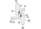
したがって、上ヘッダタンク(2)の前後両側縁部(通風方向両側縁部)に、第1〜第3タンク構成部材(20)(21)(22)の前後両側縁部に形成された縦壁部(29)(34)(36)が重なり合った積層部(38)が設けられている。積層部(38)においては、第1タンク構成部材(20)の縦壁部(29)が最も外側に位置する外側縦壁部となり、第2タンク構成部材(21)の縦壁部(34)が最も内側に位置する内側縦壁部となり、第3タンク構成部材(22)の縦壁部(36)が中間に位置する中間縦壁部となっている。 Therefore, the vertical walls formed on the front and rear side edges of the first to third tank components (20), (21) and (22) on the front and rear side edges (both sides in the ventilation direction) of the upper header tank (2) A laminated portion (38) in which the portions (29), (34), and (36) overlap is provided. In the laminated portion (38), the vertical wall portion (29) of the first tank component member (20) is the outermost vertical wall portion located on the outermost side, and the vertical wall portion (34) of the second tank component member (21). Is the inner vertical wall portion located on the innermost side, and the vertical wall portion (36) of the third tank constituting member (22) is an intermediate vertical wall portion located in the middle.
図3に詳細に示すように、第3タンク構成部材(22)の中間縦壁部(36)は、先端側に向かって通風方向外側に傾斜しており、横断面において、中間縦壁部(36)の通風方向外面と第1タンク構成部材(20)の外側縦壁部(29)の通風方向内面、および中間縦壁部(36)の通風方向内面と第2タンク構成部材(21)の内側縦壁部(34)の通風方向外面とが、それぞれ鋭角をなすように交わっている。そして、中間縦壁部(36)の通風方向外面と外側縦壁部(29)の通風方向内面との間、および中間縦壁部(36)の通風方向内面と内側縦壁部(34)の通風方向外面との間にフィレット(39)が形成されている。また、第3タンク構成部材(22)における中間縦壁部(36)の基端に連なった部分、すなわち両仕切部(23)(24)の通風方向外側縁部に、内側縦壁部(34)の先端面が当接してろう付され、中間縦壁部(36)の先端に設けられた外方突出部(37)に、外側縦壁部(29)の先端面が当接してろう付されている。 As shown in detail in FIG. 3, the intermediate vertical wall portion (36) of the third tank component (22) is inclined outward in the ventilation direction toward the distal end side, and the intermediate vertical wall portion ( 36), the outer surface of the first tank component member (20), the inner surface of the outer vertical wall portion (29), the inner surface of the intermediate vertical wall portion (36), and the second tank component member (21). The outer vertical surface of the inner vertical wall portion (34) intersects with each other so as to form an acute angle. And between the ventilation direction outer surface of the intermediate vertical wall part (36) and the ventilation direction inner surface of the outer vertical wall part (29), and between the ventilation direction inner surface of the intermediate vertical wall part (36) and the inner vertical wall part (34). A fillet (39) is formed between the outer surface in the ventilation direction. Further, the inner vertical wall portion (34) is connected to the portion of the third tank component (22) connected to the base end of the intermediate vertical wall portion (36), that is, the outer edge in the ventilation direction of the partition portions (23), (24). ) And the outer vertical wall (29) is in contact with the outer protrusion (37) provided at the tip of the intermediate vertical wall (36). Has been.
下ヘッダタンク(3)は上ヘッダタンク(2)とほぼ同様な構成であり、上ヘッダタンク(2)とは上下逆向きに配置されている。下ヘッダタンク(3)における上ヘッダタンク(2)と同一部分には同一符号を付す。なお、下ヘッダタンク(3)には冷媒入口(12)および冷媒出口(13)は設けられておらず、したがってエンド部材(25)も備えていない。そして、第1タンク構成部材(20)が風下側下ヘッダ部(8)および風上側下ヘッダ部(9)の上部を形成し、第2タンク構成部材(21)が第1タンク構成部材(20)における熱交換管(14)とは反対側(下側)を覆って風下側下ヘッダ部(8)および風上側下ヘッダ部(9)の下部を形成する。また、第3タンク構成部材(22)の前側仕切部(23)が風下側下ヘッダ部(8)内を上下方向に2つの空間(8b)(8a)に仕切り、後側仕切部(24)が風上側下ヘッダ部(9)内を上下方向に2つの空間(9b)(9a)に仕切る。風下側下ヘッダ部(8)の上下両空間(8b)(8a)は、前側仕切部(23)に形成された貫通穴(23a)により通じさせられ、風上側下ヘッダ部(9)の上下両空間(9b)(9a)は、後仕切部(24)に形成された貫通穴(24a)により通じさせられている。 The lower header tank (3) has substantially the same configuration as the upper header tank (2), and is disposed upside down with respect to the upper header tank (2). The same parts as those of the upper header tank (2) in the lower header tank (3) are denoted by the same reference numerals. The lower header tank (3) is not provided with the refrigerant inlet (12) and the refrigerant outlet (13), and therefore does not include the end member (25). The first tank component (20) forms the upper part of the leeward lower header part (8) and the windward lower header part (9), and the second tank component (21) is the first tank component (20). ) To cover the opposite side (lower side) of the heat exchange pipe (14) to form the leeward lower header part (8) and the lower part of the windward lower header part (9). The front partition (23) of the third tank component (22) partitions the leeward lower header (8) vertically into two spaces (8b) (8a), and the rear partition (24). Divides the windward lower header portion (9) into two spaces (9b) and (9a) in the vertical direction. The upper and lower spaces (8b) and (8a) of the leeward lower header section (8) are communicated by through holes (23a) formed in the front partition section (23), and the upper and lower spaces of the leeward lower header section (9). Both spaces (9b) and (9a) are connected by a through hole (24a) formed in the rear partitioning part (24).
上述したエバポレータ(1)において、圧縮機で圧縮されてコンデンサおよび膨張弁を通過した低圧の気液混相の2相冷媒が、冷媒入口(12)を通ってエバポレータ(1)の風下側上ヘッダ部(5)内に入り、全冷媒流通管(14)を通って風上側上ヘッダ部(6)の冷媒出口(13)から流出する。そして、冷媒が冷媒流通管(14)内を流れる間に、左右方向に隣り合う熱交換管(14)間の通風間隙を通過する空気と熱交換をし、冷媒は気相となって流出する。 In the evaporator (1) described above, the low-pressure gas-liquid mixed-phase two-phase refrigerant that has been compressed by the compressor and passed through the condenser and the expansion valve passes through the refrigerant inlet (12) and is on the leeward upper header portion of the evaporator (1) (5) Enters and flows out from the refrigerant outlet (13) of the windward upper header section (6) through the entire refrigerant circulation pipe (14). While the refrigerant flows in the refrigerant circulation pipe (14), heat exchange is performed with the air passing through the ventilation gap between the heat exchange pipes (14) adjacent in the left-right direction, and the refrigerant flows out as a gas phase. .
次に、上述したエバポレータ(1)の製造方法を、図4を参照して説明する。 Next, a method for manufacturing the above-described evaporator (1) will be described with reference to FIG.
第1〜第3タンク構成部材(20)(21)(22)、エンド部材(25)、熱交換管(14)、コルゲートフィン(17)およびサイドプレート(18)を用意する。さらに、第1〜第3タンク構成部材(20)(21)(22)以外の上ヘッダタンク(2)および下ヘッダタンク(3)を形成する部品を用意する。 First to third tank components (20), (21), (22), end members (25), heat exchange tubes (14), corrugated fins (17), and side plates (18) are prepared. Further, parts for forming the upper header tank (2) and the lower header tank (3) other than the first to third tank constituent members (20), (21) and (22) are prepared.
このとき、第3タンク構成部材(20)の両中間縦壁部(36)を、垂直方向外端側に向かって通風方向外側に傾斜させておき、両外側縦壁部(29)の垂直方向外端部(先端部)の内面間の間隔(L1)を、両中間縦壁部(36)の垂直方向外端部(先端部)の外面間の間隔(L2)よりも小さくするとともに、両内側縦壁部(34)の垂直方向内端部(先端部)の外面間の間隔(L3)を、両中間縦壁部(36)の垂直方向内端部(基端部)の内面間の間隔(L4)よりも大きくしておく。なお、両外側縦壁部(29)の垂直方向外端部の内面間の間隔(L1)は、両中間縦壁部(36)の垂直方向内端部の外面間の間隔よりも大きく、両内側縦壁部(34)の垂直方向内端部の外面間の間隔(L3)は、両中間縦壁部(36)の垂直方向外端部の内面間の間隔よりも小さい、。 At this time, the intermediate vertical wall portions (36) of the third tank component member (20) are inclined outwardly in the ventilation direction toward the outer end in the vertical direction, and the vertical direction of the outer vertical wall portions (29) is set. The distance (L1) between the inner surfaces of the outer ends (tips) is made smaller than the interval (L2) between the outer surfaces of the vertical outer ends (tips) of both intermediate vertical walls (36). The distance (L3) between the outer surfaces of the inner vertical wall (34) in the vertical inner end (tip) is defined as the distance between the inner surfaces of the inner vertical walls (36) in the vertical inner end (base). It is set larger than the interval (L4). Note that the distance (L1) between the inner surfaces of the vertical outer ends of both outer vertical walls (29) is larger than the distance between the outer surfaces of the inner inner vertical walls of both intermediate vertical walls (36). The distance (L3) between the outer surfaces of the inner vertical wall portions (34) in the vertical inner end is smaller than the distance between the inner surfaces of the vertical outer end portions of both intermediate vertical walls (36).
そして、第1〜第3タンク構成部材(20)(21)(22)を、両外側縦壁部(29)、両内側縦壁部(34)および両中間縦壁部(36)が積層するように組み合わせた後、第1〜第3タンク構成部材(20)(21)(22)を連結壁(28)(33)(35)においてかしめる。このとき、両外側縦壁部(29)が通風方向外側に若干開くように弾性変形するとともに、両内側縦壁部(34)が通風方向内側に若干閉じるように弾性変形し、さらに両中間縦壁部(36)が若干垂直状に近づくように弾性変形する。その結果、第3タンク構成部材(22)の仕切部(23)(24)における中間縦壁部(36)の基端に連なった部分に、内側縦壁部(34)の先端面が当接し、中間縦壁部(36)の先端部に設けられ外方突出部(37)に、外側縦壁部(29)の先端面が当接する。しかも、両外側縦壁部(29)、両内側縦壁部(34)および両中間縦壁部(36)が弾性変形することにより生じる弾性力によって、仕切部(23)(24)における中間縦壁部(36)の基端に連なった部分に、内側縦壁部(34)の先端面が押し付けられ、中間縦壁部(36)の先端部に設けられ外方突出部(37)に、外側縦壁部(29)の先端面が押し付けられることになる。 Then, the first to third tank constituent members (20), (21), and (22) are laminated on both outer vertical wall portions (29), both inner vertical wall portions (34), and both intermediate vertical wall portions (36). After the combination, the first to third tank components (20), (21), and (22) are caulked at the connecting walls (28), (33), and (35). At this time, both outer vertical wall portions (29) are elastically deformed so as to slightly open outward in the ventilation direction, and both inner vertical wall portions (34) are elastically deformed so as to be slightly closed in the ventilation direction inner side. The wall portion (36) is elastically deformed so as to be slightly vertical. As a result, the distal end surface of the inner vertical wall portion (34) comes into contact with the portion of the partition portion (23) (24) of the third tank component member (22) that is connected to the base end of the intermediate vertical wall portion (36). The distal end surface of the outer vertical wall portion (29) comes into contact with the outward projecting portion (37) provided at the distal end portion of the intermediate vertical wall portion (36). Moreover, the intermediate vertical walls in the partition portions (23) and (24) are caused by the elastic force generated by elastic deformation of the outer vertical wall portions (29), the inner vertical wall portions (34), and the intermediate vertical wall portions (36). The front end surface of the inner vertical wall portion (34) is pressed against the portion connected to the base end of the wall portion (36), and is provided at the front end portion of the intermediate vertical wall portion (36). The front end surface of the outer vertical wall portion (29) is pressed.
また、第1〜第3タンク構成部材(20)(21)(22)を組み合わせる際に、第1〜第3タンク構成部材(20)(21)(22)以外の上ヘッダタンク(2)および下ヘッダタンク(3)を形成する部品を組み合わせる。さらに、エンド部材(25)、熱交換管(14)、コルゲートフィン(17)およびサイドプレート(18)を組み合わせて全部品を仮止めする。 Further, when the first to third tank constituent members (20), (21), and (22) are combined, the upper header tank (2) other than the first to third tank constituent members (20), (21), and (22) and Combine the parts that form the lower header tank (3). Further, the end member (25), the heat exchange pipe (14), the corrugated fin (17) and the side plate (18) are combined to temporarily fix all the parts.
その後、第1〜第3タンク構成部材(20)(21)(22)、およびその他のタンク構成部品をろう付して上下両ヘッダタンク(2)(3)をつくると同時に、エンド部材(25)、熱交換管(14)、コルゲートフィン(17)およびサイドプレート(18)をろう付する。こうして、エバポレータ(1)が製造される。 Thereafter, the upper and lower header tanks (2) and (3) are made by brazing the first to third tank components (20), (21) and (22) and other tank components, and at the same time, the end members (25 ), A heat exchange pipe (14), a corrugated fin (17) and a side plate (18). Thus, the evaporator (1) is manufactured.
図5はエバポレータのヘッダタンクの変形例の要部の構成を示す。 FIG. 5 shows a configuration of a main part of a modified example of the header tank of the evaporator.
図5に示すヘッダタンクの場合、第1〜第3タンク構成部材(20)(21)(22)の縦壁部(29)(34)(36)が重なり合った積層部(38)においては、第3タンク構成部材(22)の中間縦壁部(36)の通風方向外面に、第1タンク構成部材(20)の外側縦壁部(29)の先端面の通風方向内側縁部が当接し、同じく中間縦壁部(36)の通風方向内面に、第2タンク構成部材(21)の内側縦壁部(34)の先端面の通風方向外側縁部が当接している。 In the case of the header tank shown in FIG. 5, in the laminated portion (38) in which the vertical wall portions (29), (34), and (36) of the first to third tank constituent members (20), (21), and (22) overlap, The ventilation direction inner edge of the front end surface of the outer vertical wall (29) of the first tank component (20) abuts on the outer surface of the intermediate vertical wall (36) of the third tank component (22). Similarly, the outer edge in the ventilation direction of the front end surface of the inner vertical wall (34) of the second tank component (21) is in contact with the inner surface of the intermediate vertical wall (36) in the ventilation direction.
そして、横断面において、中間縦壁部(36)の通風方向外面と第1タンク構成部材(20)の外側縦壁部(29)の通風方向内面、および中間縦壁部(36)の通風方向内面と第2タンク構成部材(21)の内側縦壁部(34)の通風方向外面とが、それぞれ鋭角をなすように交わっており、中間縦壁部(36)の通風方向外面と外側縦壁部(29)の通風方向内面との間、および中間縦壁部(36)の通風方向内面と内側縦壁部(34)の通風方向外面との間にフィレット(39)が形成されている。 And in the cross section, the ventilation direction outer surface of the intermediate vertical wall portion (36), the ventilation direction inner surface of the outer vertical wall portion (29) of the first tank component (20), and the ventilation direction of the intermediate vertical wall portion (36). The inner surface and the outer vertical wall of the inner vertical wall (34) of the second tank component (21) intersect each other so as to form an acute angle, and the outer vertical wall and the outer vertical wall of the intermediate vertical wall (36). A fillet (39) is formed between the ventilation direction inner surface of the portion (29) and between the ventilation direction inner surface of the intermediate vertical wall portion (36) and the ventilation direction outer surface of the inner vertical wall portion (34).
上記実施形態においては、第1タンク構成部材(20)の縦壁部(29)が第3タンク構成部材(22)の中間縦壁部(36)の外側に位置し、第2タンク構成部材(21)の縦壁部(34)が第3タンク構成部材(22)の中間縦壁部(36)の内側に位置しているが、これとは逆に、第1タンク構成部材(20)の縦壁部(29)が第3タンク構成部材(22)の中間縦壁部(36)の内側に位置し、第2タンク構成部材(21)の縦壁部(34)が第3タンク構成部材(22)の中間縦壁部(36)の外側に位置していてもよい。この場合、第3タンク構成部材(22)の中間縦壁部(36)を、仕切部(23)(24)に対して垂直方向内側、すなわち上ヘッダタンク(2)においては下側、下ヘッダタンク(3)においては上側に突出させるとともに、先端側に向かって通風方向外側に傾斜させる。そうすると、横断面において、中間縦壁部(36)の通風方向外面と第1タンク構成部材(20)の外側縦壁部(29)の通風方向内面、および中間縦壁部(36)の通風方向内面と第2タンク構成部材(21)の内側縦壁部(34)の通風方向外面とが、それぞれ鋭角をなすように交わる。 In the said embodiment, the vertical wall part (29) of a 1st tank structural member (20) is located in the outer side of the intermediate | middle vertical wall part (36) of a 3rd tank structural member (22), and a 2nd tank structural member ( The vertical wall portion (34) of 21) is located inside the intermediate vertical wall portion (36) of the third tank component (22), but conversely, the first tank component (20) The vertical wall portion (29) is located inside the intermediate vertical wall portion (36) of the third tank component member (22), and the vertical wall portion (34) of the second tank component member (21) is the third tank component member. It may be located outside the intermediate vertical wall (36) of (22). In this case, the intermediate vertical wall portion (36) of the third tank component (22) is vertically inward of the partition portions (23) and (24), that is, the lower and lower headers in the upper header tank (2). The tank (3) protrudes upward and is inclined outward in the ventilation direction toward the tip side. Then, in the cross section, the ventilation direction outer surface of the intermediate vertical wall portion (36), the ventilation direction inner surface of the outer vertical wall portion (29) of the first tank component (20), and the ventilation direction of the intermediate vertical wall portion (36). The inner surface and the outer surface in the ventilation direction of the inner vertical wall portion (34) of the second tank component (21) intersect each other so as to form an acute angle.
この発明による熱交換器は、カーエアコンを構成する冷凍サイクルのエバポレータとして好適に用いられる。 The heat exchanger according to the present invention is suitably used as an evaporator of a refrigeration cycle constituting a car air conditioner.
(1):エバポレータ(熱交換器)
(2):上ヘッダタンク
(3):下ヘッダタンク
(14):熱交換管
(20):第1タンク構成部材
(21):第2タンク構成部材
(22):第3タンク構成部材
(23)(24):仕切部
(29):外側縦壁部
(34):内側縦壁部
(36):中間縦壁部
(37):外方突出部
(38):積層部
(39):フィレット
(1): Evaporator (heat exchanger)
(2): Upper header tank
(3): Lower header tank
(14): Heat exchange pipe
(20): First tank component
(21): Second tank component
(22): Third tank component
(23) (24): Partition
(29): Outside vertical wall
(34): Inside vertical wall
(36): Middle vertical wall
(37): Outward protrusion
(38): Laminated part
(39): Fillet
Claims (2)
第3タンク構成部材の中間縦壁部が、先端側に向かって通風方向外側に傾斜しており、横断面において、中間縦壁部の通風方向外面と外側縦壁部の通風方向内面、および中間縦壁部の通風方向内面と内側縦壁部の通風方向外面とが、それぞれ鋭角をなすように交わっており、中間縦壁部の通風方向外面と外側縦壁部の通風方向内面との間、および中間縦壁部の通風方向内面と内側縦壁部の通風方向外面との間にフィレットが形成され、中間縦壁部の通風方向外面に、外側縦壁部の先端面の通風方向内側縁部が当接し、中間縦壁部の通風方向内面に、内側縦壁部の先端面の通風方向外側縁部が当接している熱交換器。 A pair of header tanks that are oriented in the width direction in the ventilation direction and spaced apart from each other, and a plurality of heat exchange pipes that are arranged between the header tanks and are connected at both ends to the header tanks. And at least one of the header tanks is connected to the first tank constituent member to which the heat exchange pipe is connected, and the first tank constituent member is joined to the first tank constituent member and covers the opposite side of the first tank constituent member from the heat exchange pipe. Two tank constituent members, and a third tank constituent member disposed between the first tank constituent member and the second tank constituent member, and on both side edges of the ventilation direction of the header tank having three tank constituent members , A laminated portion in which vertical wall portions formed on both side edges of each tank constituent member are overlapped is provided, and the laminated portion is an outer vertical wall portion located on the outermost side, an inner vertical wall located on the innermost side. Part, And an intermediate vertical wall portion located in the middle, an outer vertical wall portion is provided on one of the first tank constituent member and the second tank constituent member, and an inner vertical wall portion is provided on the other, A heat exchanger in which an intermediate vertical wall is provided on the three tank components,
The intermediate vertical wall portion of the third tank component member is inclined outward in the ventilation direction toward the distal end side, and in the cross section, the intermediate vertical wall portion in the ventilation direction outer surface and the outer vertical wall portion in the ventilation direction inner surface, and the intermediate The ventilation direction inner surface of the vertical wall portion and the ventilation direction outer surface of the inner vertical wall portion intersect each other so as to form an acute angle, and between the ventilation direction outer surface of the intermediate vertical wall portion and the ventilation direction inner surface of the outer vertical wall portion, And a fillet is formed between the ventilation direction inner surface of the middle vertical wall part and the ventilation direction outer surface of the inner vertical wall part, and the ventilation direction inner edge part of the front end surface of the outer vertical wall part on the ventilation direction outer surface of the intermediate vertical wall part Is in contact with the air flow direction inner surface of the intermediate vertical wall portion and the air flow direction outer edge of the front end surface of the inner vertical wall portion .
Priority Applications (5)
| Application Number | Priority Date | Filing Date | Title |
|---|---|---|---|
| JP2012084815A JP6002421B2 (en) | 2012-04-03 | 2012-04-03 | Heat exchanger |
| US13/851,966 US9523540B2 (en) | 2012-04-03 | 2013-03-28 | Heat exchanger with header tank including tank constituting members |
| DE102013205763A DE102013205763A1 (en) | 2012-04-03 | 2013-04-02 | Heat exchanger and method for producing the same |
| CN201310122278.1A CN103363727B (en) | 2012-04-03 | 2013-04-02 | Heat exchanger and its manufacture method |
| CN2013201926287U CN203216160U (en) | 2012-04-03 | 2013-04-02 | Heat exchanger |
Applications Claiming Priority (1)
| Application Number | Priority Date | Filing Date | Title |
|---|---|---|---|
| JP2012084815A JP6002421B2 (en) | 2012-04-03 | 2012-04-03 | Heat exchanger |
Publications (3)
| Publication Number | Publication Date |
|---|---|
| JP2013213636A JP2013213636A (en) | 2013-10-17 |
| JP2013213636A5 JP2013213636A5 (en) | 2015-04-30 |
| JP6002421B2 true JP6002421B2 (en) | 2016-10-05 |
Family
ID=49205687
Family Applications (1)
| Application Number | Title | Priority Date | Filing Date |
|---|---|---|---|
| JP2012084815A Expired - Fee Related JP6002421B2 (en) | 2012-04-03 | 2012-04-03 | Heat exchanger |
Country Status (4)
| Country | Link |
|---|---|
| US (1) | US9523540B2 (en) |
| JP (1) | JP6002421B2 (en) |
| CN (2) | CN203216160U (en) |
| DE (1) | DE102013205763A1 (en) |
Families Citing this family (7)
| Publication number | Priority date | Publication date | Assignee | Title |
|---|---|---|---|---|
| JP2014124971A (en) * | 2012-12-25 | 2014-07-07 | Keihin Thermal Technology Corp | Evaporator with cold storage function |
| JP2015157507A (en) * | 2014-02-21 | 2015-09-03 | 株式会社ケーヒン・サーマル・テクノロジー | Air conditioner for vehicle |
| EP2960609B1 (en) * | 2014-06-26 | 2022-10-05 | Valeo Autosystemy SP. Z.O.O. | Manifold, in particular for use in a cooler of a cooling system |
| US10670349B2 (en) * | 2017-07-18 | 2020-06-02 | General Electric Company | Additively manufactured heat exchanger |
| DE102018220139A1 (en) * | 2018-11-23 | 2020-05-28 | Mahle International Gmbh | Collecting pipe for a heat exchanger |
| DE102018220143A1 (en) | 2018-11-23 | 2020-05-28 | Mahle International Gmbh | Collecting pipe for a heat exchanger |
| DE102018220142A1 (en) | 2018-11-23 | 2020-05-28 | Mahle International Gmbh | Collecting pipe for a heat exchanger |
Family Cites Families (18)
| Publication number | Priority date | Publication date | Assignee | Title |
|---|---|---|---|---|
| USRE35098E (en) * | 1979-12-20 | 1995-11-28 | Modine Manufacturing Co. | Method of making a heat exchanger |
| FR2503346B2 (en) * | 1980-11-24 | 1986-02-21 | Chausson Usines Sa | MECHANICALLY ASSEMBLED HEAT EXCHANGER OF THE TUBE AND VANE TYPE |
| JPS58107492U (en) * | 1982-01-08 | 1983-07-21 | カルソニックカンセイ株式会社 | radiator |
| JPS6066987U (en) * | 1983-10-14 | 1985-05-13 | 本田技研工業株式会社 | Joint structure of plate and tank in radiator |
| JP2504832Y2 (en) * | 1988-10-07 | 1996-07-24 | 東洋ラジエーター 株式会社 | Brazing structure of heat exchanger tank |
| FR2690230B1 (en) * | 1992-04-21 | 1994-06-03 | Valeo Thermique Moteur Sa | HEAT EXCHANGER COMPRISING A FIXED TUBE BEAM IMMOBILIZED IN RELATION TO A COLLECTOR-WATER BOX ASSEMBLY. |
| US5934365A (en) * | 1997-08-21 | 1999-08-10 | Ford Motor Company | Heat exchanger |
| JP4164145B2 (en) * | 1998-03-30 | 2008-10-08 | 昭和電工株式会社 | Heat exchanger and car air conditioner using the same |
| US6615488B2 (en) * | 2002-02-04 | 2003-09-09 | Delphi Technologies, Inc. | Method of forming heat exchanger tube |
| DE10316756A1 (en) * | 2003-04-10 | 2004-10-28 | Behr Gmbh & Co. Kg | Heat exchangers, in particular intercoolers for motor vehicles |
| CN1950664B (en) * | 2004-05-11 | 2010-10-20 | 昭和电工株式会社 | Heat exchangers |
| US7343966B2 (en) * | 2005-06-17 | 2008-03-18 | Newfield Technology Corporation | Stamped manifold for a heat exchanger and method for making same |
| WO2007084996A2 (en) * | 2006-01-19 | 2007-07-26 | Modine Manufacturing Company | Flat tube, flat tube heat exchanger, and method of manufacturing same |
| DK2212639T3 (en) * | 2007-10-12 | 2016-09-19 | Carrier Corp | Heat exchange with baffelforgreninger |
| JP4945399B2 (en) * | 2007-10-16 | 2012-06-06 | 昭和電工株式会社 | Heat exchanger |
| EP2159528B1 (en) * | 2008-09-02 | 2015-11-04 | Calsonic Kansei Corporation | Heat exchanger made of aluminum alloy |
| JP2010112695A (en) | 2008-10-07 | 2010-05-20 | Showa Denko Kk | Evaporator |
| JP2011064379A (en) * | 2009-09-16 | 2011-03-31 | Showa Denko Kk | Heat exchanger |
-
2012
- 2012-04-03 JP JP2012084815A patent/JP6002421B2/en not_active Expired - Fee Related
-
2013
- 2013-03-28 US US13/851,966 patent/US9523540B2/en active Active
- 2013-04-02 CN CN2013201926287U patent/CN203216160U/en not_active Expired - Fee Related
- 2013-04-02 DE DE102013205763A patent/DE102013205763A1/en not_active Withdrawn
- 2013-04-02 CN CN201310122278.1A patent/CN103363727B/en active Active
Also Published As
| Publication number | Publication date |
|---|---|
| CN103363727A (en) | 2013-10-23 |
| US20130255926A1 (en) | 2013-10-03 |
| DE102013205763A1 (en) | 2013-10-10 |
| JP2013213636A (en) | 2013-10-17 |
| CN103363727B (en) | 2017-09-26 |
| US9523540B2 (en) | 2016-12-20 |
| CN203216160U (en) | 2013-09-25 |
Similar Documents
| Publication | Publication Date | Title |
|---|---|---|
| JP6002421B2 (en) | Heat exchanger | |
| JP6035089B2 (en) | Heat exchanger | |
| JP2005326135A (en) | Heat exchanger | |
| JP6050978B2 (en) | Evaporator | |
| WO2011049015A1 (en) | Evaporator | |
| JP2006078163A (en) | Flat tube, plate body for manufacturing flat tube, and heat exchanger | |
| JP2011163666A (en) | Heat exchanger | |
| JP2011163666A5 (en) | ||
| JP5990402B2 (en) | Heat exchanger | |
| JP2013024517A (en) | Laminated heat exchanger | |
| JP4972488B2 (en) | Heat exchanger | |
| JP4898672B2 (en) | Heat exchanger | |
| JP2011185562A (en) | Condenser | |
| JP5070144B2 (en) | Heat exchanger | |
| JP5574737B2 (en) | Heat exchanger | |
| JP2009113625A (en) | Evaporator | |
| JP2011163700A5 (en) | ||
| JP2009299923A (en) | Heat exchanger | |
| JP2009287907A (en) | Heat exchanger | |
| JP2011163700A (en) | Heat exchanger | |
| JP2008089188A (en) | Heat exchanger | |
| JP2009008347A (en) | Heat exchanger | |
| JP2005090946A (en) | Heat exchanger and evaporator | |
| JP2007178017A (en) | Heat exchanger | |
| JP2006029765A (en) | Heat exchanger |
Legal Events
| Date | Code | Title | Description |
|---|---|---|---|
| A521 | Request for written amendment filed |
Free format text: JAPANESE INTERMEDIATE CODE: A523 Effective date: 20150317 |
|
| A621 | Written request for application examination |
Free format text: JAPANESE INTERMEDIATE CODE: A621 Effective date: 20150317 |
|
| A977 | Report on retrieval |
Free format text: JAPANESE INTERMEDIATE CODE: A971007 Effective date: 20160112 |
|
| A131 | Notification of reasons for refusal |
Free format text: JAPANESE INTERMEDIATE CODE: A131 Effective date: 20160209 |
|
| A521 | Request for written amendment filed |
Free format text: JAPANESE INTERMEDIATE CODE: A523 Effective date: 20160324 |
|
| TRDD | Decision of grant or rejection written | ||
| A01 | Written decision to grant a patent or to grant a registration (utility model) |
Free format text: JAPANESE INTERMEDIATE CODE: A01 Effective date: 20160809 |
|
| A61 | First payment of annual fees (during grant procedure) |
Free format text: JAPANESE INTERMEDIATE CODE: A61 Effective date: 20160905 |
|
| R150 | Certificate of patent or registration of utility model |
Ref document number: 6002421 Country of ref document: JP Free format text: JAPANESE INTERMEDIATE CODE: R150 |
|
| R250 | Receipt of annual fees |
Free format text: JAPANESE INTERMEDIATE CODE: R250 |
|
| R250 | Receipt of annual fees |
Free format text: JAPANESE INTERMEDIATE CODE: R250 |
|
| S533 | Written request for registration of change of name |
Free format text: JAPANESE INTERMEDIATE CODE: R313533 |
|
| R350 | Written notification of registration of transfer |
Free format text: JAPANESE INTERMEDIATE CODE: R350 |
|
| LAPS | Cancellation because of no payment of annual fees |