JP2010001017A - Vehicle - Google Patents
Vehicle Download PDFInfo
- Publication number
- JP2010001017A JP2010001017A JP2009184679A JP2009184679A JP2010001017A JP 2010001017 A JP2010001017 A JP 2010001017A JP 2009184679 A JP2009184679 A JP 2009184679A JP 2009184679 A JP2009184679 A JP 2009184679A JP 2010001017 A JP2010001017 A JP 2010001017A
- Authority
- JP
- Japan
- Prior art keywords
- unit
- lid member
- state
- energy
- energy source
- Prior art date
- Legal status (The legal status is an assumption and is not a legal conclusion. Google has not performed a legal analysis and makes no representation as to the accuracy of the status listed.)
- Granted
Links
- 230000007246 mechanism Effects 0.000 claims abstract description 106
- 239000000446 fuel Substances 0.000 claims description 44
- 230000007935 neutral effect Effects 0.000 claims description 26
- 239000003990 capacitor Substances 0.000 claims description 22
- 238000004804 winding Methods 0.000 claims description 16
- 238000005259 measurement Methods 0.000 claims description 10
- 238000001514 detection method Methods 0.000 claims description 9
- 239000002828 fuel tank Substances 0.000 claims description 9
- 239000007788 liquid Substances 0.000 claims description 5
- 238000009825 accumulation Methods 0.000 claims description 4
- 230000008878 coupling Effects 0.000 claims 1
- 238000010168 coupling process Methods 0.000 claims 1
- 238000005859 coupling reaction Methods 0.000 claims 1
- 239000003502 gasoline Substances 0.000 abstract description 7
- 238000000034 method Methods 0.000 description 54
- 230000008569 process Effects 0.000 description 48
- 238000012545 processing Methods 0.000 description 48
- 238000010586 diagram Methods 0.000 description 23
- 238000003780 insertion Methods 0.000 description 22
- 230000037431 insertion Effects 0.000 description 22
- 238000012840 feeding operation Methods 0.000 description 5
- 230000004048 modification Effects 0.000 description 5
- 238000012986 modification Methods 0.000 description 5
- 238000002485 combustion reaction Methods 0.000 description 4
- 230000004308 accommodation Effects 0.000 description 3
- 239000007789 gas Substances 0.000 description 3
- 101150049032 ACL1 gene Proteins 0.000 description 2
- 101100448894 Arabidopsis thaliana GLR3.1 gene Proteins 0.000 description 2
- 101100054598 Hordeum vulgare ACL1.2 gene Proteins 0.000 description 2
- UFHFLCQGNIYNRP-UHFFFAOYSA-N Hydrogen Chemical compound [H][H] UFHFLCQGNIYNRP-UHFFFAOYSA-N 0.000 description 2
- 230000002159 abnormal effect Effects 0.000 description 2
- 230000005856 abnormality Effects 0.000 description 2
- 101150023061 acpP gene Proteins 0.000 description 2
- 238000007599 discharging Methods 0.000 description 2
- 239000001257 hydrogen Substances 0.000 description 2
- 229910052739 hydrogen Inorganic materials 0.000 description 2
- 229910052751 metal Inorganic materials 0.000 description 2
- 239000002184 metal Substances 0.000 description 2
- VNWKTOKETHGBQD-UHFFFAOYSA-N methane Chemical compound C VNWKTOKETHGBQD-UHFFFAOYSA-N 0.000 description 2
- HBBGRARXTFLTSG-UHFFFAOYSA-N Lithium ion Chemical compound [Li+] HBBGRARXTFLTSG-UHFFFAOYSA-N 0.000 description 1
- 230000008859 change Effects 0.000 description 1
- 230000000694 effects Effects 0.000 description 1
- 230000005611 electricity Effects 0.000 description 1
- 230000007613 environmental effect Effects 0.000 description 1
- 239000000945 filler Substances 0.000 description 1
- 230000009931 harmful effect Effects 0.000 description 1
- 230000001939 inductive effect Effects 0.000 description 1
- 230000002452 interceptive effect Effects 0.000 description 1
- 230000016507 interphase Effects 0.000 description 1
- 229910001416 lithium ion Inorganic materials 0.000 description 1
- 229910052987 metal hydride Inorganic materials 0.000 description 1
- 239000003345 natural gas Substances 0.000 description 1
- 229910052759 nickel Inorganic materials 0.000 description 1
- PXHVJJICTQNCMI-UHFFFAOYSA-N nickel Substances [Ni] PXHVJJICTQNCMI-UHFFFAOYSA-N 0.000 description 1
- -1 nickel metal hydride Chemical class 0.000 description 1
- 230000002093 peripheral effect Effects 0.000 description 1
- 230000009467 reduction Effects 0.000 description 1
- 230000001172 regenerating effect Effects 0.000 description 1
Images


Classifications
-
- B—PERFORMING OPERATIONS; TRANSPORTING
- B60—VEHICLES IN GENERAL
- B60W—CONJOINT CONTROL OF VEHICLE SUB-UNITS OF DIFFERENT TYPE OR DIFFERENT FUNCTION; CONTROL SYSTEMS SPECIALLY ADAPTED FOR HYBRID VEHICLES; ROAD VEHICLE DRIVE CONTROL SYSTEMS FOR PURPOSES NOT RELATED TO THE CONTROL OF A PARTICULAR SUB-UNIT
- B60W20/00—Control systems specially adapted for hybrid vehicles
-
- B—PERFORMING OPERATIONS; TRANSPORTING
- B60—VEHICLES IN GENERAL
- B60K—ARRANGEMENT OR MOUNTING OF PROPULSION UNITS OR OF TRANSMISSIONS IN VEHICLES; ARRANGEMENT OR MOUNTING OF PLURAL DIVERSE PRIME-MOVERS IN VEHICLES; AUXILIARY DRIVES FOR VEHICLES; INSTRUMENTATION OR DASHBOARDS FOR VEHICLES; ARRANGEMENTS IN CONNECTION WITH COOLING, AIR INTAKE, GAS EXHAUST OR FUEL SUPPLY OF PROPULSION UNITS IN VEHICLES
- B60K1/00—Arrangement or mounting of electrical propulsion units
- B60K1/04—Arrangement or mounting of electrical propulsion units of the electric storage means for propulsion
-
- B—PERFORMING OPERATIONS; TRANSPORTING
- B60—VEHICLES IN GENERAL
- B60K—ARRANGEMENT OR MOUNTING OF PROPULSION UNITS OR OF TRANSMISSIONS IN VEHICLES; ARRANGEMENT OR MOUNTING OF PLURAL DIVERSE PRIME-MOVERS IN VEHICLES; AUXILIARY DRIVES FOR VEHICLES; INSTRUMENTATION OR DASHBOARDS FOR VEHICLES; ARRANGEMENTS IN CONNECTION WITH COOLING, AIR INTAKE, GAS EXHAUST OR FUEL SUPPLY OF PROPULSION UNITS IN VEHICLES
- B60K15/00—Arrangement in connection with fuel supply of combustion engines or other fuel consuming energy converters, e.g. fuel cells; Mounting or construction of fuel tanks
- B60K15/03—Fuel tanks
- B60K15/04—Tank inlets
- B60K15/05—Inlet covers
-
- B—PERFORMING OPERATIONS; TRANSPORTING
- B60—VEHICLES IN GENERAL
- B60K—ARRANGEMENT OR MOUNTING OF PROPULSION UNITS OR OF TRANSMISSIONS IN VEHICLES; ARRANGEMENT OR MOUNTING OF PLURAL DIVERSE PRIME-MOVERS IN VEHICLES; AUXILIARY DRIVES FOR VEHICLES; INSTRUMENTATION OR DASHBOARDS FOR VEHICLES; ARRANGEMENTS IN CONNECTION WITH COOLING, AIR INTAKE, GAS EXHAUST OR FUEL SUPPLY OF PROPULSION UNITS IN VEHICLES
- B60K6/00—Arrangement or mounting of plural diverse prime-movers for mutual or common propulsion, e.g. hybrid propulsion systems comprising electric motors and internal combustion engines ; Control systems therefor, i.e. systems controlling two or more prime movers, or controlling one of these prime movers and any of the transmission, drive or drive units Informative references: mechanical gearings with secondary electric drive F16H3/72; arrangements for handling mechanical energy structurally associated with the dynamo-electric machine H02K7/00; machines comprising structurally interrelated motor and generator parts H02K51/00; dynamo-electric machines not otherwise provided for in H02K see H02K99/00
- B60K6/20—Arrangement or mounting of plural diverse prime-movers for mutual or common propulsion, e.g. hybrid propulsion systems comprising electric motors and internal combustion engines ; Control systems therefor, i.e. systems controlling two or more prime movers, or controlling one of these prime movers and any of the transmission, drive or drive units Informative references: mechanical gearings with secondary electric drive F16H3/72; arrangements for handling mechanical energy structurally associated with the dynamo-electric machine H02K7/00; machines comprising structurally interrelated motor and generator parts H02K51/00; dynamo-electric machines not otherwise provided for in H02K see H02K99/00 the prime-movers consisting of electric motors and internal combustion engines, e.g. HEVs
- B60K6/22—Arrangement or mounting of plural diverse prime-movers for mutual or common propulsion, e.g. hybrid propulsion systems comprising electric motors and internal combustion engines ; Control systems therefor, i.e. systems controlling two or more prime movers, or controlling one of these prime movers and any of the transmission, drive or drive units Informative references: mechanical gearings with secondary electric drive F16H3/72; arrangements for handling mechanical energy structurally associated with the dynamo-electric machine H02K7/00; machines comprising structurally interrelated motor and generator parts H02K51/00; dynamo-electric machines not otherwise provided for in H02K see H02K99/00 the prime-movers consisting of electric motors and internal combustion engines, e.g. HEVs characterised by apparatus, components or means specially adapted for HEVs
- B60K6/36—Arrangement or mounting of plural diverse prime-movers for mutual or common propulsion, e.g. hybrid propulsion systems comprising electric motors and internal combustion engines ; Control systems therefor, i.e. systems controlling two or more prime movers, or controlling one of these prime movers and any of the transmission, drive or drive units Informative references: mechanical gearings with secondary electric drive F16H3/72; arrangements for handling mechanical energy structurally associated with the dynamo-electric machine H02K7/00; machines comprising structurally interrelated motor and generator parts H02K51/00; dynamo-electric machines not otherwise provided for in H02K see H02K99/00 the prime-movers consisting of electric motors and internal combustion engines, e.g. HEVs characterised by apparatus, components or means specially adapted for HEVs characterised by the transmission gearings
- B60K6/365—Arrangement or mounting of plural diverse prime-movers for mutual or common propulsion, e.g. hybrid propulsion systems comprising electric motors and internal combustion engines ; Control systems therefor, i.e. systems controlling two or more prime movers, or controlling one of these prime movers and any of the transmission, drive or drive units Informative references: mechanical gearings with secondary electric drive F16H3/72; arrangements for handling mechanical energy structurally associated with the dynamo-electric machine H02K7/00; machines comprising structurally interrelated motor and generator parts H02K51/00; dynamo-electric machines not otherwise provided for in H02K see H02K99/00 the prime-movers consisting of electric motors and internal combustion engines, e.g. HEVs characterised by apparatus, components or means specially adapted for HEVs characterised by the transmission gearings with the gears having orbital motion
-
- B—PERFORMING OPERATIONS; TRANSPORTING
- B60—VEHICLES IN GENERAL
- B60K—ARRANGEMENT OR MOUNTING OF PROPULSION UNITS OR OF TRANSMISSIONS IN VEHICLES; ARRANGEMENT OR MOUNTING OF PLURAL DIVERSE PRIME-MOVERS IN VEHICLES; AUXILIARY DRIVES FOR VEHICLES; INSTRUMENTATION OR DASHBOARDS FOR VEHICLES; ARRANGEMENTS IN CONNECTION WITH COOLING, AIR INTAKE, GAS EXHAUST OR FUEL SUPPLY OF PROPULSION UNITS IN VEHICLES
- B60K6/00—Arrangement or mounting of plural diverse prime-movers for mutual or common propulsion, e.g. hybrid propulsion systems comprising electric motors and internal combustion engines ; Control systems therefor, i.e. systems controlling two or more prime movers, or controlling one of these prime movers and any of the transmission, drive or drive units Informative references: mechanical gearings with secondary electric drive F16H3/72; arrangements for handling mechanical energy structurally associated with the dynamo-electric machine H02K7/00; machines comprising structurally interrelated motor and generator parts H02K51/00; dynamo-electric machines not otherwise provided for in H02K see H02K99/00
- B60K6/20—Arrangement or mounting of plural diverse prime-movers for mutual or common propulsion, e.g. hybrid propulsion systems comprising electric motors and internal combustion engines ; Control systems therefor, i.e. systems controlling two or more prime movers, or controlling one of these prime movers and any of the transmission, drive or drive units Informative references: mechanical gearings with secondary electric drive F16H3/72; arrangements for handling mechanical energy structurally associated with the dynamo-electric machine H02K7/00; machines comprising structurally interrelated motor and generator parts H02K51/00; dynamo-electric machines not otherwise provided for in H02K see H02K99/00 the prime-movers consisting of electric motors and internal combustion engines, e.g. HEVs
- B60K6/42—Arrangement or mounting of plural diverse prime-movers for mutual or common propulsion, e.g. hybrid propulsion systems comprising electric motors and internal combustion engines ; Control systems therefor, i.e. systems controlling two or more prime movers, or controlling one of these prime movers and any of the transmission, drive or drive units Informative references: mechanical gearings with secondary electric drive F16H3/72; arrangements for handling mechanical energy structurally associated with the dynamo-electric machine H02K7/00; machines comprising structurally interrelated motor and generator parts H02K51/00; dynamo-electric machines not otherwise provided for in H02K see H02K99/00 the prime-movers consisting of electric motors and internal combustion engines, e.g. HEVs characterised by the architecture of the hybrid electric vehicle
- B60K6/44—Series-parallel type
- B60K6/445—Differential gearing distribution type
-
- B—PERFORMING OPERATIONS; TRANSPORTING
- B60—VEHICLES IN GENERAL
- B60L—PROPULSION OF ELECTRICALLY-PROPELLED VEHICLES; SUPPLYING ELECTRIC POWER FOR AUXILIARY EQUIPMENT OF ELECTRICALLY-PROPELLED VEHICLES; ELECTRODYNAMIC BRAKE SYSTEMS FOR VEHICLES IN GENERAL; MAGNETIC SUSPENSION OR LEVITATION FOR VEHICLES; MONITORING OPERATING VARIABLES OF ELECTRICALLY-PROPELLED VEHICLES; ELECTRIC SAFETY DEVICES FOR ELECTRICALLY-PROPELLED VEHICLES
- B60L15/00—Methods, circuits, or devices for controlling the traction-motor speed of electrically-propelled vehicles
- B60L15/007—Physical arrangements or structures of drive train converters specially adapted for the propulsion motors of electric vehicles
-
- B—PERFORMING OPERATIONS; TRANSPORTING
- B60—VEHICLES IN GENERAL
- B60L—PROPULSION OF ELECTRICALLY-PROPELLED VEHICLES; SUPPLYING ELECTRIC POWER FOR AUXILIARY EQUIPMENT OF ELECTRICALLY-PROPELLED VEHICLES; ELECTRODYNAMIC BRAKE SYSTEMS FOR VEHICLES IN GENERAL; MAGNETIC SUSPENSION OR LEVITATION FOR VEHICLES; MONITORING OPERATING VARIABLES OF ELECTRICALLY-PROPELLED VEHICLES; ELECTRIC SAFETY DEVICES FOR ELECTRICALLY-PROPELLED VEHICLES
- B60L50/00—Electric propulsion with power supplied within the vehicle
- B60L50/10—Electric propulsion with power supplied within the vehicle using propulsion power supplied by engine-driven generators, e.g. generators driven by combustion engines
- B60L50/16—Electric propulsion with power supplied within the vehicle using propulsion power supplied by engine-driven generators, e.g. generators driven by combustion engines with provision for separate direct mechanical propulsion
-
- B—PERFORMING OPERATIONS; TRANSPORTING
- B60—VEHICLES IN GENERAL
- B60L—PROPULSION OF ELECTRICALLY-PROPELLED VEHICLES; SUPPLYING ELECTRIC POWER FOR AUXILIARY EQUIPMENT OF ELECTRICALLY-PROPELLED VEHICLES; ELECTRODYNAMIC BRAKE SYSTEMS FOR VEHICLES IN GENERAL; MAGNETIC SUSPENSION OR LEVITATION FOR VEHICLES; MONITORING OPERATING VARIABLES OF ELECTRICALLY-PROPELLED VEHICLES; ELECTRIC SAFETY DEVICES FOR ELECTRICALLY-PROPELLED VEHICLES
- B60L50/00—Electric propulsion with power supplied within the vehicle
- B60L50/50—Electric propulsion with power supplied within the vehicle using propulsion power supplied by batteries or fuel cells
- B60L50/60—Electric propulsion with power supplied within the vehicle using propulsion power supplied by batteries or fuel cells using power supplied by batteries
- B60L50/61—Electric propulsion with power supplied within the vehicle using propulsion power supplied by batteries or fuel cells using power supplied by batteries by batteries charged by engine-driven generators, e.g. series hybrid electric vehicles
-
- B—PERFORMING OPERATIONS; TRANSPORTING
- B60—VEHICLES IN GENERAL
- B60L—PROPULSION OF ELECTRICALLY-PROPELLED VEHICLES; SUPPLYING ELECTRIC POWER FOR AUXILIARY EQUIPMENT OF ELECTRICALLY-PROPELLED VEHICLES; ELECTRODYNAMIC BRAKE SYSTEMS FOR VEHICLES IN GENERAL; MAGNETIC SUSPENSION OR LEVITATION FOR VEHICLES; MONITORING OPERATING VARIABLES OF ELECTRICALLY-PROPELLED VEHICLES; ELECTRIC SAFETY DEVICES FOR ELECTRICALLY-PROPELLED VEHICLES
- B60L53/00—Methods of charging batteries, specially adapted for electric vehicles; Charging stations or on-board charging equipment therefor; Exchange of energy storage elements in electric vehicles
- B60L53/10—Methods of charging batteries, specially adapted for electric vehicles; Charging stations or on-board charging equipment therefor; Exchange of energy storage elements in electric vehicles characterised by the energy transfer between the charging station and the vehicle
- B60L53/12—Inductive energy transfer
- B60L53/124—Detection or removal of foreign bodies
-
- B—PERFORMING OPERATIONS; TRANSPORTING
- B60—VEHICLES IN GENERAL
- B60L—PROPULSION OF ELECTRICALLY-PROPELLED VEHICLES; SUPPLYING ELECTRIC POWER FOR AUXILIARY EQUIPMENT OF ELECTRICALLY-PROPELLED VEHICLES; ELECTRODYNAMIC BRAKE SYSTEMS FOR VEHICLES IN GENERAL; MAGNETIC SUSPENSION OR LEVITATION FOR VEHICLES; MONITORING OPERATING VARIABLES OF ELECTRICALLY-PROPELLED VEHICLES; ELECTRIC SAFETY DEVICES FOR ELECTRICALLY-PROPELLED VEHICLES
- B60L53/00—Methods of charging batteries, specially adapted for electric vehicles; Charging stations or on-board charging equipment therefor; Exchange of energy storage elements in electric vehicles
- B60L53/10—Methods of charging batteries, specially adapted for electric vehicles; Charging stations or on-board charging equipment therefor; Exchange of energy storage elements in electric vehicles characterised by the energy transfer between the charging station and the vehicle
- B60L53/12—Inductive energy transfer
- B60L53/126—Methods for pairing a vehicle and a charging station, e.g. establishing a one-to-one relation between a wireless power transmitter and a wireless power receiver
-
- B—PERFORMING OPERATIONS; TRANSPORTING
- B60—VEHICLES IN GENERAL
- B60L—PROPULSION OF ELECTRICALLY-PROPELLED VEHICLES; SUPPLYING ELECTRIC POWER FOR AUXILIARY EQUIPMENT OF ELECTRICALLY-PROPELLED VEHICLES; ELECTRODYNAMIC BRAKE SYSTEMS FOR VEHICLES IN GENERAL; MAGNETIC SUSPENSION OR LEVITATION FOR VEHICLES; MONITORING OPERATING VARIABLES OF ELECTRICALLY-PROPELLED VEHICLES; ELECTRIC SAFETY DEVICES FOR ELECTRICALLY-PROPELLED VEHICLES
- B60L53/00—Methods of charging batteries, specially adapted for electric vehicles; Charging stations or on-board charging equipment therefor; Exchange of energy storage elements in electric vehicles
- B60L53/10—Methods of charging batteries, specially adapted for electric vehicles; Charging stations or on-board charging equipment therefor; Exchange of energy storage elements in electric vehicles characterised by the energy transfer between the charging station and the vehicle
- B60L53/14—Conductive energy transfer
- B60L53/16—Connectors, e.g. plugs or sockets, specially adapted for charging electric vehicles
-
- B—PERFORMING OPERATIONS; TRANSPORTING
- B60—VEHICLES IN GENERAL
- B60L—PROPULSION OF ELECTRICALLY-PROPELLED VEHICLES; SUPPLYING ELECTRIC POWER FOR AUXILIARY EQUIPMENT OF ELECTRICALLY-PROPELLED VEHICLES; ELECTRODYNAMIC BRAKE SYSTEMS FOR VEHICLES IN GENERAL; MAGNETIC SUSPENSION OR LEVITATION FOR VEHICLES; MONITORING OPERATING VARIABLES OF ELECTRICALLY-PROPELLED VEHICLES; ELECTRIC SAFETY DEVICES FOR ELECTRICALLY-PROPELLED VEHICLES
- B60L53/00—Methods of charging batteries, specially adapted for electric vehicles; Charging stations or on-board charging equipment therefor; Exchange of energy storage elements in electric vehicles
- B60L53/20—Methods of charging batteries, specially adapted for electric vehicles; Charging stations or on-board charging equipment therefor; Exchange of energy storage elements in electric vehicles characterised by converters located in the vehicle
- B60L53/22—Constructional details or arrangements of charging converters specially adapted for charging electric vehicles
-
- B—PERFORMING OPERATIONS; TRANSPORTING
- B60—VEHICLES IN GENERAL
- B60L—PROPULSION OF ELECTRICALLY-PROPELLED VEHICLES; SUPPLYING ELECTRIC POWER FOR AUXILIARY EQUIPMENT OF ELECTRICALLY-PROPELLED VEHICLES; ELECTRODYNAMIC BRAKE SYSTEMS FOR VEHICLES IN GENERAL; MAGNETIC SUSPENSION OR LEVITATION FOR VEHICLES; MONITORING OPERATING VARIABLES OF ELECTRICALLY-PROPELLED VEHICLES; ELECTRIC SAFETY DEVICES FOR ELECTRICALLY-PROPELLED VEHICLES
- B60L53/00—Methods of charging batteries, specially adapted for electric vehicles; Charging stations or on-board charging equipment therefor; Exchange of energy storage elements in electric vehicles
- B60L53/20—Methods of charging batteries, specially adapted for electric vehicles; Charging stations or on-board charging equipment therefor; Exchange of energy storage elements in electric vehicles characterised by converters located in the vehicle
- B60L53/24—Using the vehicle's propulsion converter for charging
-
- B—PERFORMING OPERATIONS; TRANSPORTING
- B60—VEHICLES IN GENERAL
- B60W—CONJOINT CONTROL OF VEHICLE SUB-UNITS OF DIFFERENT TYPE OR DIFFERENT FUNCTION; CONTROL SYSTEMS SPECIALLY ADAPTED FOR HYBRID VEHICLES; ROAD VEHICLE DRIVE CONTROL SYSTEMS FOR PURPOSES NOT RELATED TO THE CONTROL OF A PARTICULAR SUB-UNIT
- B60W10/00—Conjoint control of vehicle sub-units of different type or different function
- B60W10/04—Conjoint control of vehicle sub-units of different type or different function including control of propulsion units
- B60W10/08—Conjoint control of vehicle sub-units of different type or different function including control of propulsion units including control of electric propulsion units, e.g. motors or generators
-
- B—PERFORMING OPERATIONS; TRANSPORTING
- B60—VEHICLES IN GENERAL
- B60W—CONJOINT CONTROL OF VEHICLE SUB-UNITS OF DIFFERENT TYPE OR DIFFERENT FUNCTION; CONTROL SYSTEMS SPECIALLY ADAPTED FOR HYBRID VEHICLES; ROAD VEHICLE DRIVE CONTROL SYSTEMS FOR PURPOSES NOT RELATED TO THE CONTROL OF A PARTICULAR SUB-UNIT
- B60W10/00—Conjoint control of vehicle sub-units of different type or different function
- B60W10/24—Conjoint control of vehicle sub-units of different type or different function including control of energy storage means
- B60W10/26—Conjoint control of vehicle sub-units of different type or different function including control of energy storage means for electrical energy, e.g. batteries or capacitors
-
- E—FIXED CONSTRUCTIONS
- E05—LOCKS; KEYS; WINDOW OR DOOR FITTINGS; SAFES
- E05B—LOCKS; ACCESSORIES THEREFOR; HANDCUFFS
- E05B81/00—Power-actuated vehicle locks
- E05B81/12—Power-actuated vehicle locks characterised by the function or purpose of the powered actuators
- E05B81/14—Power-actuated vehicle locks characterised by the function or purpose of the powered actuators operating on bolt detents, e.g. for unlatching the bolt
-
- E—FIXED CONSTRUCTIONS
- E05—LOCKS; KEYS; WINDOW OR DOOR FITTINGS; SAFES
- E05B—LOCKS; ACCESSORIES THEREFOR; HANDCUFFS
- E05B83/00—Vehicle locks specially adapted for particular types of wing or vehicle
- E05B83/28—Locks for glove compartments, console boxes, fuel inlet covers or the like
- E05B83/34—Locks for glove compartments, console boxes, fuel inlet covers or the like for fuel inlet covers essentially flush with the vehicle surface
-
- B—PERFORMING OPERATIONS; TRANSPORTING
- B60—VEHICLES IN GENERAL
- B60K—ARRANGEMENT OR MOUNTING OF PROPULSION UNITS OR OF TRANSMISSIONS IN VEHICLES; ARRANGEMENT OR MOUNTING OF PLURAL DIVERSE PRIME-MOVERS IN VEHICLES; AUXILIARY DRIVES FOR VEHICLES; INSTRUMENTATION OR DASHBOARDS FOR VEHICLES; ARRANGEMENTS IN CONNECTION WITH COOLING, AIR INTAKE, GAS EXHAUST OR FUEL SUPPLY OF PROPULSION UNITS IN VEHICLES
- B60K1/00—Arrangement or mounting of electrical propulsion units
- B60K1/02—Arrangement or mounting of electrical propulsion units comprising more than one electric motor
-
- B—PERFORMING OPERATIONS; TRANSPORTING
- B60—VEHICLES IN GENERAL
- B60K—ARRANGEMENT OR MOUNTING OF PROPULSION UNITS OR OF TRANSMISSIONS IN VEHICLES; ARRANGEMENT OR MOUNTING OF PLURAL DIVERSE PRIME-MOVERS IN VEHICLES; AUXILIARY DRIVES FOR VEHICLES; INSTRUMENTATION OR DASHBOARDS FOR VEHICLES; ARRANGEMENTS IN CONNECTION WITH COOLING, AIR INTAKE, GAS EXHAUST OR FUEL SUPPLY OF PROPULSION UNITS IN VEHICLES
- B60K1/00—Arrangement or mounting of electrical propulsion units
- B60K1/04—Arrangement or mounting of electrical propulsion units of the electric storage means for propulsion
- B60K2001/0405—Arrangement or mounting of electrical propulsion units of the electric storage means for propulsion characterised by their position
- B60K2001/0416—Arrangement in the rear part of the vehicle
-
- B—PERFORMING OPERATIONS; TRANSPORTING
- B60—VEHICLES IN GENERAL
- B60K—ARRANGEMENT OR MOUNTING OF PROPULSION UNITS OR OF TRANSMISSIONS IN VEHICLES; ARRANGEMENT OR MOUNTING OF PLURAL DIVERSE PRIME-MOVERS IN VEHICLES; AUXILIARY DRIVES FOR VEHICLES; INSTRUMENTATION OR DASHBOARDS FOR VEHICLES; ARRANGEMENTS IN CONNECTION WITH COOLING, AIR INTAKE, GAS EXHAUST OR FUEL SUPPLY OF PROPULSION UNITS IN VEHICLES
- B60K15/00—Arrangement in connection with fuel supply of combustion engines or other fuel consuming energy converters, e.g. fuel cells; Mounting or construction of fuel tanks
- B60K15/03—Fuel tanks
- B60K15/04—Tank inlets
- B60K15/05—Inlet covers
- B60K2015/0546—Arrangements for checking the position of the inlet cover
-
- B—PERFORMING OPERATIONS; TRANSPORTING
- B60—VEHICLES IN GENERAL
- B60K—ARRANGEMENT OR MOUNTING OF PROPULSION UNITS OR OF TRANSMISSIONS IN VEHICLES; ARRANGEMENT OR MOUNTING OF PLURAL DIVERSE PRIME-MOVERS IN VEHICLES; AUXILIARY DRIVES FOR VEHICLES; INSTRUMENTATION OR DASHBOARDS FOR VEHICLES; ARRANGEMENTS IN CONNECTION WITH COOLING, AIR INTAKE, GAS EXHAUST OR FUEL SUPPLY OF PROPULSION UNITS IN VEHICLES
- B60K15/00—Arrangement in connection with fuel supply of combustion engines or other fuel consuming energy converters, e.g. fuel cells; Mounting or construction of fuel tanks
- B60K15/03—Fuel tanks
- B60K15/04—Tank inlets
- B60K15/05—Inlet covers
- B60K2015/0561—Locking means for the inlet cover
- B60K2015/0576—Locking means for the inlet cover with actuator fixed to the vehicle body
-
- B—PERFORMING OPERATIONS; TRANSPORTING
- B60—VEHICLES IN GENERAL
- B60L—PROPULSION OF ELECTRICALLY-PROPELLED VEHICLES; SUPPLYING ELECTRIC POWER FOR AUXILIARY EQUIPMENT OF ELECTRICALLY-PROPELLED VEHICLES; ELECTRODYNAMIC BRAKE SYSTEMS FOR VEHICLES IN GENERAL; MAGNETIC SUSPENSION OR LEVITATION FOR VEHICLES; MONITORING OPERATING VARIABLES OF ELECTRICALLY-PROPELLED VEHICLES; ELECTRIC SAFETY DEVICES FOR ELECTRICALLY-PROPELLED VEHICLES
- B60L2210/00—Converter types
- B60L2210/10—DC to DC converters
- B60L2210/14—Boost converters
-
- B—PERFORMING OPERATIONS; TRANSPORTING
- B60—VEHICLES IN GENERAL
- B60L—PROPULSION OF ELECTRICALLY-PROPELLED VEHICLES; SUPPLYING ELECTRIC POWER FOR AUXILIARY EQUIPMENT OF ELECTRICALLY-PROPELLED VEHICLES; ELECTRODYNAMIC BRAKE SYSTEMS FOR VEHICLES IN GENERAL; MAGNETIC SUSPENSION OR LEVITATION FOR VEHICLES; MONITORING OPERATING VARIABLES OF ELECTRICALLY-PROPELLED VEHICLES; ELECTRIC SAFETY DEVICES FOR ELECTRICALLY-PROPELLED VEHICLES
- B60L2210/00—Converter types
- B60L2210/40—DC to AC converters
-
- B—PERFORMING OPERATIONS; TRANSPORTING
- B60—VEHICLES IN GENERAL
- B60L—PROPULSION OF ELECTRICALLY-PROPELLED VEHICLES; SUPPLYING ELECTRIC POWER FOR AUXILIARY EQUIPMENT OF ELECTRICALLY-PROPELLED VEHICLES; ELECTRODYNAMIC BRAKE SYSTEMS FOR VEHICLES IN GENERAL; MAGNETIC SUSPENSION OR LEVITATION FOR VEHICLES; MONITORING OPERATING VARIABLES OF ELECTRICALLY-PROPELLED VEHICLES; ELECTRIC SAFETY DEVICES FOR ELECTRICALLY-PROPELLED VEHICLES
- B60L2220/00—Electrical machine types; Structures or applications thereof
- B60L2220/50—Structural details of electrical machines
- B60L2220/54—Windings for different functions
-
- B—PERFORMING OPERATIONS; TRANSPORTING
- B60—VEHICLES IN GENERAL
- B60L—PROPULSION OF ELECTRICALLY-PROPELLED VEHICLES; SUPPLYING ELECTRIC POWER FOR AUXILIARY EQUIPMENT OF ELECTRICALLY-PROPELLED VEHICLES; ELECTRODYNAMIC BRAKE SYSTEMS FOR VEHICLES IN GENERAL; MAGNETIC SUSPENSION OR LEVITATION FOR VEHICLES; MONITORING OPERATING VARIABLES OF ELECTRICALLY-PROPELLED VEHICLES; ELECTRIC SAFETY DEVICES FOR ELECTRICALLY-PROPELLED VEHICLES
- B60L2240/00—Control parameters of input or output; Target parameters
- B60L2240/80—Time limits
-
- B—PERFORMING OPERATIONS; TRANSPORTING
- B60—VEHICLES IN GENERAL
- B60L—PROPULSION OF ELECTRICALLY-PROPELLED VEHICLES; SUPPLYING ELECTRIC POWER FOR AUXILIARY EQUIPMENT OF ELECTRICALLY-PROPELLED VEHICLES; ELECTRODYNAMIC BRAKE SYSTEMS FOR VEHICLES IN GENERAL; MAGNETIC SUSPENSION OR LEVITATION FOR VEHICLES; MONITORING OPERATING VARIABLES OF ELECTRICALLY-PROPELLED VEHICLES; ELECTRIC SAFETY DEVICES FOR ELECTRICALLY-PROPELLED VEHICLES
- B60L2250/00—Driver interactions
- B60L2250/10—Driver interactions by alarm
-
- B—PERFORMING OPERATIONS; TRANSPORTING
- B60—VEHICLES IN GENERAL
- B60L—PROPULSION OF ELECTRICALLY-PROPELLED VEHICLES; SUPPLYING ELECTRIC POWER FOR AUXILIARY EQUIPMENT OF ELECTRICALLY-PROPELLED VEHICLES; ELECTRODYNAMIC BRAKE SYSTEMS FOR VEHICLES IN GENERAL; MAGNETIC SUSPENSION OR LEVITATION FOR VEHICLES; MONITORING OPERATING VARIABLES OF ELECTRICALLY-PROPELLED VEHICLES; ELECTRIC SAFETY DEVICES FOR ELECTRICALLY-PROPELLED VEHICLES
- B60L2250/00—Driver interactions
- B60L2250/16—Driver interactions by display
-
- B—PERFORMING OPERATIONS; TRANSPORTING
- B60—VEHICLES IN GENERAL
- B60L—PROPULSION OF ELECTRICALLY-PROPELLED VEHICLES; SUPPLYING ELECTRIC POWER FOR AUXILIARY EQUIPMENT OF ELECTRICALLY-PROPELLED VEHICLES; ELECTRODYNAMIC BRAKE SYSTEMS FOR VEHICLES IN GENERAL; MAGNETIC SUSPENSION OR LEVITATION FOR VEHICLES; MONITORING OPERATING VARIABLES OF ELECTRICALLY-PROPELLED VEHICLES; ELECTRIC SAFETY DEVICES FOR ELECTRICALLY-PROPELLED VEHICLES
- B60L2270/00—Problem solutions or means not otherwise provided for
- B60L2270/30—Preventing theft during charging
- B60L2270/32—Preventing theft during charging of electricity
-
- B—PERFORMING OPERATIONS; TRANSPORTING
- B60—VEHICLES IN GENERAL
- B60L—PROPULSION OF ELECTRICALLY-PROPELLED VEHICLES; SUPPLYING ELECTRIC POWER FOR AUXILIARY EQUIPMENT OF ELECTRICALLY-PROPELLED VEHICLES; ELECTRODYNAMIC BRAKE SYSTEMS FOR VEHICLES IN GENERAL; MAGNETIC SUSPENSION OR LEVITATION FOR VEHICLES; MONITORING OPERATING VARIABLES OF ELECTRICALLY-PROPELLED VEHICLES; ELECTRIC SAFETY DEVICES FOR ELECTRICALLY-PROPELLED VEHICLES
- B60L2270/00—Problem solutions or means not otherwise provided for
- B60L2270/30—Preventing theft during charging
- B60L2270/34—Preventing theft during charging of parts
-
- B—PERFORMING OPERATIONS; TRANSPORTING
- B60—VEHICLES IN GENERAL
- B60W—CONJOINT CONTROL OF VEHICLE SUB-UNITS OF DIFFERENT TYPE OR DIFFERENT FUNCTION; CONTROL SYSTEMS SPECIALLY ADAPTED FOR HYBRID VEHICLES; ROAD VEHICLE DRIVE CONTROL SYSTEMS FOR PURPOSES NOT RELATED TO THE CONTROL OF A PARTICULAR SUB-UNIT
- B60W50/00—Details of control systems for road vehicle drive control not related to the control of a particular sub-unit, e.g. process diagnostic or vehicle driver interfaces
- B60W50/08—Interaction between the driver and the control system
- B60W50/14—Means for informing the driver, warning the driver or prompting a driver intervention
- B60W2050/146—Display means
-
- Y—GENERAL TAGGING OF NEW TECHNOLOGICAL DEVELOPMENTS; GENERAL TAGGING OF CROSS-SECTIONAL TECHNOLOGIES SPANNING OVER SEVERAL SECTIONS OF THE IPC; TECHNICAL SUBJECTS COVERED BY FORMER USPC CROSS-REFERENCE ART COLLECTIONS [XRACs] AND DIGESTS
- Y02—TECHNOLOGIES OR APPLICATIONS FOR MITIGATION OR ADAPTATION AGAINST CLIMATE CHANGE
- Y02T—CLIMATE CHANGE MITIGATION TECHNOLOGIES RELATED TO TRANSPORTATION
- Y02T10/00—Road transport of goods or passengers
- Y02T10/60—Other road transportation technologies with climate change mitigation effect
- Y02T10/62—Hybrid vehicles
-
- Y—GENERAL TAGGING OF NEW TECHNOLOGICAL DEVELOPMENTS; GENERAL TAGGING OF CROSS-SECTIONAL TECHNOLOGIES SPANNING OVER SEVERAL SECTIONS OF THE IPC; TECHNICAL SUBJECTS COVERED BY FORMER USPC CROSS-REFERENCE ART COLLECTIONS [XRACs] AND DIGESTS
- Y02—TECHNOLOGIES OR APPLICATIONS FOR MITIGATION OR ADAPTATION AGAINST CLIMATE CHANGE
- Y02T—CLIMATE CHANGE MITIGATION TECHNOLOGIES RELATED TO TRANSPORTATION
- Y02T10/00—Road transport of goods or passengers
- Y02T10/60—Other road transportation technologies with climate change mitigation effect
- Y02T10/64—Electric machine technologies in electromobility
-
- Y—GENERAL TAGGING OF NEW TECHNOLOGICAL DEVELOPMENTS; GENERAL TAGGING OF CROSS-SECTIONAL TECHNOLOGIES SPANNING OVER SEVERAL SECTIONS OF THE IPC; TECHNICAL SUBJECTS COVERED BY FORMER USPC CROSS-REFERENCE ART COLLECTIONS [XRACs] AND DIGESTS
- Y02—TECHNOLOGIES OR APPLICATIONS FOR MITIGATION OR ADAPTATION AGAINST CLIMATE CHANGE
- Y02T—CLIMATE CHANGE MITIGATION TECHNOLOGIES RELATED TO TRANSPORTATION
- Y02T10/00—Road transport of goods or passengers
- Y02T10/60—Other road transportation technologies with climate change mitigation effect
- Y02T10/70—Energy storage systems for electromobility, e.g. batteries
-
- Y—GENERAL TAGGING OF NEW TECHNOLOGICAL DEVELOPMENTS; GENERAL TAGGING OF CROSS-SECTIONAL TECHNOLOGIES SPANNING OVER SEVERAL SECTIONS OF THE IPC; TECHNICAL SUBJECTS COVERED BY FORMER USPC CROSS-REFERENCE ART COLLECTIONS [XRACs] AND DIGESTS
- Y02—TECHNOLOGIES OR APPLICATIONS FOR MITIGATION OR ADAPTATION AGAINST CLIMATE CHANGE
- Y02T—CLIMATE CHANGE MITIGATION TECHNOLOGIES RELATED TO TRANSPORTATION
- Y02T10/00—Road transport of goods or passengers
- Y02T10/60—Other road transportation technologies with climate change mitigation effect
- Y02T10/7072—Electromobility specific charging systems or methods for batteries, ultracapacitors, supercapacitors or double-layer capacitors
-
- Y—GENERAL TAGGING OF NEW TECHNOLOGICAL DEVELOPMENTS; GENERAL TAGGING OF CROSS-SECTIONAL TECHNOLOGIES SPANNING OVER SEVERAL SECTIONS OF THE IPC; TECHNICAL SUBJECTS COVERED BY FORMER USPC CROSS-REFERENCE ART COLLECTIONS [XRACs] AND DIGESTS
- Y02—TECHNOLOGIES OR APPLICATIONS FOR MITIGATION OR ADAPTATION AGAINST CLIMATE CHANGE
- Y02T—CLIMATE CHANGE MITIGATION TECHNOLOGIES RELATED TO TRANSPORTATION
- Y02T10/00—Road transport of goods or passengers
- Y02T10/60—Other road transportation technologies with climate change mitigation effect
- Y02T10/72—Electric energy management in electromobility
-
- Y—GENERAL TAGGING OF NEW TECHNOLOGICAL DEVELOPMENTS; GENERAL TAGGING OF CROSS-SECTIONAL TECHNOLOGIES SPANNING OVER SEVERAL SECTIONS OF THE IPC; TECHNICAL SUBJECTS COVERED BY FORMER USPC CROSS-REFERENCE ART COLLECTIONS [XRACs] AND DIGESTS
- Y02—TECHNOLOGIES OR APPLICATIONS FOR MITIGATION OR ADAPTATION AGAINST CLIMATE CHANGE
- Y02T—CLIMATE CHANGE MITIGATION TECHNOLOGIES RELATED TO TRANSPORTATION
- Y02T90/00—Enabling technologies or technologies with a potential or indirect contribution to GHG emissions mitigation
- Y02T90/10—Technologies relating to charging of electric vehicles
- Y02T90/12—Electric charging stations
-
- Y—GENERAL TAGGING OF NEW TECHNOLOGICAL DEVELOPMENTS; GENERAL TAGGING OF CROSS-SECTIONAL TECHNOLOGIES SPANNING OVER SEVERAL SECTIONS OF THE IPC; TECHNICAL SUBJECTS COVERED BY FORMER USPC CROSS-REFERENCE ART COLLECTIONS [XRACs] AND DIGESTS
- Y02—TECHNOLOGIES OR APPLICATIONS FOR MITIGATION OR ADAPTATION AGAINST CLIMATE CHANGE
- Y02T—CLIMATE CHANGE MITIGATION TECHNOLOGIES RELATED TO TRANSPORTATION
- Y02T90/00—Enabling technologies or technologies with a potential or indirect contribution to GHG emissions mitigation
- Y02T90/10—Technologies relating to charging of electric vehicles
- Y02T90/14—Plug-in electric vehicles
-
- Y—GENERAL TAGGING OF NEW TECHNOLOGICAL DEVELOPMENTS; GENERAL TAGGING OF CROSS-SECTIONAL TECHNOLOGIES SPANNING OVER SEVERAL SECTIONS OF THE IPC; TECHNICAL SUBJECTS COVERED BY FORMER USPC CROSS-REFERENCE ART COLLECTIONS [XRACs] AND DIGESTS
- Y10—TECHNICAL SUBJECTS COVERED BY FORMER USPC
- Y10S—TECHNICAL SUBJECTS COVERED BY FORMER USPC CROSS-REFERENCE ART COLLECTIONS [XRACs] AND DIGESTS
- Y10S903/00—Hybrid electric vehicles, HEVS
- Y10S903/902—Prime movers comprising electrical and internal combustion motors
- Y10S903/903—Prime movers comprising electrical and internal combustion motors having energy storing means, e.g. battery, capacitor
- Y10S903/93—Conjoint control of different elements
Abstract
Description
本発明は、車両に関し、特に複数種類のエネルギ源が供給される車両に関する。 The present invention relates to a vehicle, and more particularly to a vehicle supplied with a plurality of types of energy sources.
近年、環境問題に配慮されたハイブリッド車両や燃料電池車両等が各種提案されている。たとえば、特許第3016349号公報には、燃料使用制限式ハイブリッド車両が提案されている。この燃料使用制限式ハイブリッド車両は、外部充電しうるバッテリと、このバッテリからの電力により車輪を駆動しうる駆動用電動機と、この駆動電動機へ電力を供給しうる発電機を駆動する内燃機関とを備えている。そして、この燃料使用制限式ハイブリッド車両は、外部充電手段によって充電されてからの内燃機関による燃料使用量の変化を検出する燃料使用量検出手段を備える。この燃料使用量検出手段からのパラメータが所定値となると、電動機の出力を制限することで、ドライバが内燃機関に頼らないで走行するように案内する。 In recent years, various types of hybrid vehicles, fuel cell vehicles, and the like in consideration of environmental problems have been proposed. For example, Japanese Patent No. 3016349 proposes a fuel use-restricted hybrid vehicle. This fuel use-restricted hybrid vehicle includes a battery that can be externally charged, a drive motor that can drive wheels by the power from the battery, and an internal combustion engine that drives a generator that can supply power to the drive motor. I have. The fuel use-restricted hybrid vehicle includes fuel use amount detection means for detecting a change in fuel use amount by the internal combustion engine after being charged by the external charging means. When the parameter from the fuel usage amount detecting means reaches a predetermined value, the driver is guided so as to travel without depending on the internal combustion engine by limiting the output of the electric motor.
特開2005−93316号公報に記載され燃料電池車両は、燃料タンクから供給される燃料および空気供給源から供給される空気により燃料電池で電気を発生させる燃料電池装置と、バッテリと、モータとを備えている。 A fuel cell vehicle described in Japanese Patent Application Laid-Open No. 2005-93316 includes a fuel cell device that generates electricity in a fuel cell using fuel supplied from a fuel tank and air supplied from an air supply source, a battery, and a motor. I have.
さらに、特開平6−135302号公報には、電気自動車やガソリン自動車の給油設備と、電気自動車の充電設備とを備えた自動車のサービスステーションが提案されている。このサービスステーションにおいては、エアカーテンを設けると共に、充電中に発生するガスを上部に排出する排出口を備えている。これにより、このサービスステーションにおいては、給油中に生じる気化ガスや、充電中に生じるガスを排出することができる。 Further, Japanese Patent Application Laid-Open No. 6-135302 proposes an automobile service station provided with a fueling facility for an electric vehicle or a gasoline vehicle and a charging facility for the electric vehicle. In this service station, an air curtain is provided and a discharge port for discharging gas generated during charging to the upper portion is provided. Thereby, in this service station, vaporized gas generated during refueling and gas generated during charging can be discharged.
なお、特開平11−78527号公報には、スライドドアがフューエルリッドや給油ガンと干渉することが抑制された車両が記載されている。 Japanese Patent Application Laid-Open No. 11-78527 describes a vehicle in which the sliding door is suppressed from interfering with a fuel lid or a fuel gun.
しかし、上記ハイブリッド車両においては、充電口に外部充電手段を挿入しつつ、給油口に給油ガンを挿入することができる。そして、充電作業や給油作業を行う作業者が、給油作業と充電作業とを同時に行った場合には、各種作業を同時に行う必要が生じて、作業者による作業ミスが頻発するおそれがある。さらに、特開2005−93316号公報および特開平6−135302号公報のいずれにおいても、充電、給油作業を行う作業者の作業ミスの低減との観点から何等提案も示唆もされていない。 However, in the hybrid vehicle, the fuel gun can be inserted into the fuel filler port while the external charging means is inserted into the charge port. When an operator who performs a charging operation or a refueling operation performs the refueling operation and the charging operation at the same time, it is necessary to perform various operations at the same time, and there is a risk of frequent operation errors by the operator. Furthermore, neither Japanese Patent Application Laid-Open No. 2005-93316 and Japanese Patent Application Laid-Open No. Hei 6-135302 make any suggestion or suggestion from the viewpoint of reducing work mistakes of workers who perform charging and refueling operations.
本発明は、上記のような課題に鑑みてなされたものであって、その目的は、充電作業や給油作業を行う作業者によって引き起こされる作業ミスの低減が図られた車両を提供することである。 The present invention has been made in view of the above problems, and an object of the present invention is to provide a vehicle in which a work error caused by a worker who performs a charging operation or a refueling operation is reduced. .
本発明に係る車両は、第1エネルギ源によって、駆動される第1駆動部と、第1エネルギ源を蓄積可能な第1蓄積部と、第1エネルギ供給部が着脱可能に接続され、第1エネル
ギ源が供給される第1エネルギ受入部と、第1エネルギ受入部を収容する第1収容室の開口部を開閉する第1蓋部材と、第1エネルギ受入部に接続され、第1エネルギ受入部に供給された第1エネルギ源を第1蓄積部に導く第1接続部とを備える。そして、この車両は、上記第1エネルギ源と異なる第2エネルギ源によって駆動する第2駆動部と、第2エネルギ源を蓄積する第2蓄積部と、第2エネルギ供給部が着脱可能に接続され、第2エネルギ源が供給される第2エネルギ受入部と、第2エネルギ受入部を収容する第2収容室の開口部を開閉可能とする第2蓋部材と、第2エネルギ受入部に接続され、第2エネルギ受入部に供給された第2エネルギ源が流通する第2接続部とを備える。さらに、この車両は、上記第1蓋部材と第2蓋部材との一方が開状態とされたときに、他方を閉状態に維持する開閉制御機構を備える。
In the vehicle according to the present invention, a first drive unit driven by a first energy source, a first accumulation unit capable of accumulating the first energy source, and a first energy supply unit are detachably connected to each other. A first energy receiving unit to which an energy source is supplied; a first lid member that opens and closes an opening of a first storage chamber that houses the first energy receiving unit; and a first energy receiving unit that is connected to the first energy receiving unit. And a first connection part for guiding the first energy source supplied to the part to the first storage part. In this vehicle, a second drive unit that is driven by a second energy source different from the first energy source, a second accumulation unit that accumulates the second energy source, and a second energy supply unit are detachably connected. A second energy receiving unit to which a second energy source is supplied; a second lid member capable of opening and closing an opening of a second storage chamber that houses the second energy receiving unit; and a second energy receiving unit. And a second connection part through which the second energy source supplied to the second energy receiving part flows. The vehicle further includes an opening / closing control mechanism that maintains the other closed state when one of the first lid member and the second lid member is opened.
好ましくは、上記開閉制御機構は、第1蓋部材の開閉状態を検出する第1検出部と、第2蓋部材の開閉状態を検出する第2検出部と、第1蓋部材を閉状態に維持する第1ロック部とを備える。さらに、上記開閉制御機構は、第2蓋部材を閉状態に維持する第2ロック部と、第1ロック部による第1蓋部材の閉状態を解除可能な第1解除部と、第2ロック部による第2蓋部材の閉状態を解除可能な第2解除部と、第1検出部が第1蓋部材の開状態を検出したときに、第2解除部の駆動を禁止し、第2検出部が第2蓋部材の開状態を検出したときに、第1解除部の駆動を禁止する制御部とを含む。 Preferably, the opening / closing control mechanism maintains a first detection unit that detects an open / closed state of the first lid member, a second detection unit that detects an open / closed state of the second lid member, and the first lid member in a closed state. And a first lock portion. Further, the opening / closing control mechanism includes a second lock portion that maintains the second lid member in a closed state, a first release portion that can release the closed state of the first lid member by the first lock portion, and a second lock portion. A second release part capable of releasing the closed state of the second lid member by the first and the second detection part prohibiting driving of the second release part when the first detection part detects the open state of the first lid member; Includes a control unit that prohibits driving of the first release unit when the open state of the second lid member is detected.
好ましくは、上記第1エネルギ源は燃料とされ、第1蓄積部は、液体状の燃料を蓄積する燃料タンクとされ、第1接続部は、液体状の燃料を第1エネルギ受入部から燃料タンクに導く管路とされる。さらに、上記第2エネルギ源は電力とされ、第2蓄積部は、直流電力として、第2エネルギ源を蓄積する蓄電器とされ、第2接続部は、電力が流通する配線とされる。 Preferably, the first energy source is a fuel, the first accumulation unit is a fuel tank that accumulates liquid fuel, and the first connection unit is a fuel tank that stores liquid fuel from the first energy receiving unit. It is considered as a conduit that leads to Further, the second energy source is electric power, the second accumulating unit is a capacitor for accumulating the second energy source as DC power, and the second connecting unit is a wiring through which electric power flows.
好ましくは、上記第2駆動部は、交流電力としての第2エネルギ源によって駆動される回転電機とされ、回転電機は、第1多相巻線と該第1多相巻線の第1中性点とを有する第1回転電機と、第2多相巻線と該第2多相巻線の第2中性点とを有する第2回転電機とを含む。さらに、上記第2接続部は、第1中性点に接続された第1配線と、第2中性点に接続された第2配線とを含み、記蓄電器からの直流電力としての第2エネルギ源を交流電力としての第2エネルギ源に変換して第1回転電機に供給する第1インバータと、蓄電器からの直流電力としての第2エネルギ源を交流電力としての第2エネルギ源に変換して第2回転電機に供給する第2インバータと、第1および第2インバータを制御するインバータ制御部とをさらに備える。そして、上記ンバータ制御部は、第2接続部から第1および第2中性点に与えられる交流電力を直流電力に変換して、蓄電器に供給するように第1および第2インバータを制御する。 Preferably, the second drive unit is a rotating electrical machine driven by a second energy source as AC power, and the rotating electrical machine includes a first multiphase winding and a first neutral of the first multiphase winding. A first rotating electrical machine having a point, and a second rotating electrical machine having a second multiphase winding and a second neutral point of the second multiphase winding. Further, the second connection portion includes a first wiring connected to the first neutral point and a second wiring connected to the second neutral point, and the second energy as DC power from the storage battery. A first inverter that converts the power source into a second energy source as AC power and supplies it to the first rotating electrical machine, and a second energy source that functions as DC power from the capacitor is converted into a second energy source as AC power A second inverter supplied to the second rotating electrical machine and an inverter control unit for controlling the first and second inverters are further provided. The inverter control unit controls the first and second inverters so as to convert the AC power applied from the second connection unit to the first and second neutral points into DC power and supply the DC power.
好ましくは、上記第2駆動部は、交流電力としての第2エネルギ源によって駆動される回転電機とされ、回転電機は、第1多相巻線と該第1多相巻線の第1中性点とを有する第1回転電機と、第2多相巻線と該第2多相巻線の第2中性点とを有する第2回転電機とを含む。そして、上記第2接続部は、第1中性点に接続された第1配線と、第2中性点に接続された第2配線とを含み、蓄電器からの直流電力としての第2エネルギ源を交流電力としての第2エネルギ源に変換して第1回転電機に供給する第1インバータと、蓄電器に直流電力としての第2エネルギ源を交流電力としての第2エネルギ源に変換して第1回転電機に供給する第2インバータと、第1および第2インバータを制御するインバータ制御部とをさらに備える。そして、上記インバータ制御部は、蓄電器から第1インバータおよび第2インバータに供給される直流電力を交流電力に変換して、第2接続部から外部負荷に供給するように第1インバータおよび第2インバータを制御する。 Preferably, the second drive unit is a rotating electrical machine driven by a second energy source as AC power, and the rotating electrical machine includes a first multiphase winding and a first neutral of the first multiphase winding. A first rotating electrical machine having a point, and a second rotating electrical machine having a second multiphase winding and a second neutral point of the second multiphase winding. The second connection portion includes a first wiring connected to the first neutral point and a second wiring connected to the second neutral point, and a second energy source as DC power from the capacitor. Is converted into a second energy source as AC power and supplied to the first rotating electrical machine, and a second energy source as DC power is converted into a second energy source as AC power in the capacitor and is converted into a first energy source. A second inverter supplied to the rotating electrical machine and an inverter control unit for controlling the first and second inverters are further provided. The inverter control unit converts the DC power supplied from the battery to the first inverter and the second inverter into AC power, and supplies the AC power to the external load from the second connection unit. To control.
好ましくは、上記開閉制御機構は、第1蓋部材と第2蓋部材とを連結して、第1蓋部材
と第2蓋部材と連動させて、第1蓋部材および第2蓋部材とのいずれもが開状態となることを抑制する連結部材を含む。
Preferably, the opening / closing control mechanism connects the first lid member and the second lid member and interlocks with the first lid member and the second lid member, so that either the first lid member or the second lid member is connected. The connection member which suppresses that an open state will be included.
好ましくは、上記連結部材は、第1蓋部材と第2蓋部材とを連結するワイヤを含む。好ましくは、上記開閉制御機構は、第1蓋部材を開閉可能状態とすると共に、第2蓋部材を閉状態とする第1状態と、第2蓋部材を開閉可能状態とすると共に、第1蓋部材を閉状態とする第2状態とに切り替え可能な操作機構を含む。そして、上記操作機構は、使用者によって切替操作可能な操作部と、操作部および第1蓋部材を連結する第1操作用連結部材と、操作部および第2蓋部材を連結する第2操作用連結部材とを含む。そして、上記操作機構が第1状態とされることで、第1操作用連結部材に延び代を設けて、第1蓋部材を開閉可能とすると共に、第2操作用連結部材の延び代を低減させて、第2蓋部材を閉状態とする。また、上記操作部が第2状態とされることで、第1操作用連結部材の延び代を低減して、第2蓋部材を閉状態とすると共に、第2操作用連結部材に延び代を設けて、第2蓋部材を開閉可能とする。 Preferably, the connection member includes a wire for connecting the first lid member and the second lid member. Preferably, the open / close control mechanism has a first lid member in a state where the first lid member can be opened and closed, a first state where the second lid member is closed, and a second lid member which is openable and closable. An operation mechanism that can be switched to a second state in which the member is closed is included. The operation mechanism includes an operation unit that can be switched by a user, a first operation connecting member that connects the operation unit and the first lid member, and a second operation unit that connects the operation unit and the second lid member. A connecting member. When the operation mechanism is in the first state, an extension margin is provided in the first operation connecting member so that the first lid member can be opened and closed, and the extension margin of the second operation connecting member is reduced. Then, the second lid member is closed. In addition, since the operation portion is in the second state, the extension margin of the first operation connecting member is reduced, the second lid member is closed, and the extension margin of the second operation connecting member is increased. The second lid member can be opened and closed.
好ましくは、上記操作部は、回転可能に設けられた回転部材と、回転部材を回転可能に支持する軸部とを含む。そして、上記第1操作用連結部材は、回転部材のうち、軸部から離れた位置に接続され、第2操作用連結部材は、回転部材のうち、軸部に対して、第1操作用連結部が接続された部分と反対側に位置する部分に接続する。 Preferably, the operation unit includes a rotation member that is rotatably provided and a shaft portion that rotatably supports the rotation member. The first operation connecting member is connected to a position away from the shaft portion of the rotating member, and the second operation connecting member is connected to the shaft portion of the rotating member. The part is connected to the part located on the opposite side of the connected part.
本発明に係る車両は、第1エネルギ源によって、駆動される第1駆動部と、第1エネルギ源を蓄積可能な第1蓄積部と、第1エネルギを供給可能な第1エネルギ供給部が着脱可能に接続され、第1エネルギ源が供給される第1エネルギ受入部と、第1エネルギ受入部を収容する第1収容室の開口部を開閉する第1蓋部材と、第1エネルギ受入部に接続され、第1エネルギ受入部に供給された第1エネルギ源を第1蓄積部に導く第1接続部と、第1エネルギ源と異なる第2エネルギ源によって駆動する第2駆動部と、第2エネルギ源を蓄積する第2蓄積部と、第2エネルギ供給部が着脱可能に接続され、第2エネルギ源が供給される第2エネルギ受入部と、第2エネルギ受入部を収容する第2収容室の開口部を開閉可能とする第2蓋部材と、第2エネルギ受入部に接続され、第2エネルギ受入部に供給された第2エネルギ源が流通する第2接続部と、第1蓋部材および第2蓋部材との開閉制御を行う開閉制御装置と、警告動作を行う警告部を含む出力部とを備える。そして、上記開閉制御装置は、第1蓋部材および第2蓋部材の開閉状態を判定する蓋開閉判定部と、蓋開閉判定部からの開閉情報に基づいて、出力部を駆動する出力部駆動部とを含む。さらに、上記出力部駆動部は、第1蓋部材および第2蓋部材の少なくとも一方が開状態のときに、警告部を駆動し、第1蓋部材および第2蓋部材のいずれもが閉状態となると、警告部の駆動を停止する。 The vehicle according to the present invention includes a first drive unit driven by a first energy source, a first storage unit capable of storing the first energy source, and a first energy supply unit capable of supplying the first energy. A first energy receiving portion connected to the first energy source; a first lid member for opening and closing an opening of the first storage chamber for storing the first energy receiving portion; and a first energy receiving portion. A first connection part that leads the first energy source connected to the first energy receiving part to the first storage part, a second drive part that is driven by a second energy source different from the first energy source, and a second A second storage section that stores the energy source, a second energy supply section that is detachably connected to the second energy supply section, and that is supplied with the second energy source, and a second storage chamber that stores the second energy reception section. A second lid member capable of opening and closing the opening of the second lid member; A second connection unit connected to the energy receiving unit and through which the second energy source supplied to the second energy receiving unit circulates; an open / close control device that controls opening and closing of the first lid member and the second lid member; And an output unit including a warning unit for performing an operation. The open / close control device includes a lid open / close determining unit that determines open / closed states of the first lid member and the second lid member, and an output unit driving unit that drives the output unit based on the open / close information from the lid open / close determining unit. Including. Further, the output unit driving unit drives the warning unit when at least one of the first lid member and the second lid member is in an open state, and both the first lid member and the second lid member are in a closed state. Then, the driving of the warning unit is stopped.
好ましくは、上記出力部は、開状態の第1蓋部材を駆動して閉状態とする第1蓋駆動部と、開状態の第2蓋部材を駆動して閉状態とする第2蓋駆動部とを含む。そして、上記開閉制御装置は、第1エネルギ受入部における第1エネルギ供給部の接続状態、および第2エネルギ受入部おける第2エネルギ供給部の接続状態を判定し、出力部駆動部に接続情報を送る接続状態判定部を含む。さらに、上記出力部駆動部は、第1蓋部材および第2蓋部材が開状態であって、第1エネルギ受入部に第1エネルギ供給部が接続されておらず、第2エネルギ受入部に第2エネルギ供給部が接続されていないときに、第1および第2蓋駆動部を駆動する。 Preferably, the output unit drives a first lid member in an open state to be closed, and a second lid drive unit to drive and close a second lid member in an open state. Including. The opening / closing control device determines a connection state of the first energy supply unit in the first energy receiving unit and a connection state of the second energy supply unit in the second energy reception unit, and provides connection information to the output unit driving unit. A connection state determination unit to be sent is included. Further, in the output unit driving unit, the first lid member and the second lid member are in an open state, the first energy supply unit is not connected to the first energy receiving unit, and the second energy receiving unit is connected to the second energy receiving unit. When the two energy supply units are not connected, the first and second lid driving units are driven.
さらに、上記出力部駆動部は、第1蓋部材および第2蓋部材が開状態であって、第1エネルギ受入部に第1エネルギ供給部が接続されておらず、第2エネルギ受入部に第2エネルギ供給部が接続されているときに、第1蓋駆動部を駆動する。上記出力部駆動部は、第1蓋部材および第2蓋部材が開状態であって、第1エネルギ受入部に第1エネルギ供給部
が接続されており、第2エネルギ受入部に第2エネルギ供給部が接続されていないときに、第2蓋駆動部を駆動する。
Further, in the output unit driving unit, the first lid member and the second lid member are in an open state, the first energy supply unit is not connected to the first energy receiving unit, and the second energy receiving unit is connected to the second energy receiving unit. When the two energy supply units are connected, the first lid driving unit is driven. In the output unit drive unit, the first lid member and the second lid member are in an open state, the first energy supply unit is connected to the first energy reception unit, and the second energy supply unit is supplied to the second energy reception unit. When the unit is not connected, the second lid driving unit is driven.
好ましくは、上記開閉制御装置は、第1蓋部材の開状態の期間を測定し、第1測定情報を出力部駆動部に送る第1測定部と、第2蓋部材の開状態の期間を測定し、第2測定情報を出力部駆動部に送る第2測定部とを含む。さらに、上記出力部は、第1蓋部材を駆動して閉状態とする第1蓋駆動部、および第2蓋部材を駆動して閉状態とする第2蓋駆動部を含む。そして、上記開閉制御装置は、第1エネルギ受入部における第1エネルギ供給部の接続状態、および第2エネルギ受入部おける第2エネルギ供給部の接続状態を判定し、出力部駆動部に接続情報を送る接続状態判定部を含む。さらに、上記出力部駆動部は、第1蓋部材が開状態、第2蓋部材が閉状態、および第1エネルギ受入部に第1エネルギ供給部が接続されていない状態が所定期間継続したときに、第1蓋駆動部を駆動する。そして、上記出力部駆動部は、第2蓋部材が開状態、第1蓋部材が閉状態、および第2エネルギ受入部に第2エネルギ供給部が接続されていない状態が所定期間継続したときに、第2蓋駆動部を駆動する。 Preferably, the opening / closing control device measures the period of the open state of the first lid member, measures the first measurement unit that sends the first measurement information to the output unit driving unit, and measures the period of the open state of the second lid member And a second measuring unit that sends the second measurement information to the output unit driving unit. Further, the output unit includes a first lid driving unit that drives the first lid member to be in a closed state, and a second lid driving unit that drives the second lid member to be in a closed state. The opening / closing control device determines a connection state of the first energy supply unit in the first energy receiving unit and a connection state of the second energy supply unit in the second energy reception unit, and provides connection information to the output unit driving unit. A connection state determination unit for sending is included. Further, the output unit drive unit is configured to perform a predetermined period of time when the first lid member is in the open state, the second lid member is in the closed state, and the first energy supply unit is not connected to the first energy receiving unit. The first lid driving unit is driven. When the second lid member is in an open state, the first lid member is in a closed state, and a state in which the second energy supply unit is not connected to the second energy receiving unit is continued for a predetermined period. The second lid driving unit is driven.
好ましくは、上記開閉制御装置は、第1蓋駆動部の駆動時間を測定し、第3測定情報を出力部駆動部に送る第3測定部と、第2蓋駆動部の駆動時間を測定し、第4測定情報を出力部駆動部に送る第4測定部とを含む。そして、上記出力部駆動部は、第1駆動部の駆動時間が所定時間より長くなると、第1駆動部の駆動を停止して、警告部を駆動する。さらに、上記出力部駆動部は、第2駆動部の駆動時間が所定時間より長くなると、第2駆動部の駆動を停止して、警告部を駆動する。 Preferably, the open / close control device measures a driving time of the first lid driving unit, measures a driving time of the second lid driving unit, a third measuring unit that sends third measurement information to the output unit driving unit, And a fourth measurement unit that sends the fourth measurement information to the output unit drive unit. Then, when the driving time of the first driving unit becomes longer than the predetermined time, the output unit driving unit stops driving the first driving unit and drives the warning unit. Furthermore, when the driving time of the second driving unit becomes longer than a predetermined time, the output unit driving unit stops driving the second driving unit and drives the warning unit.
本発明に係る車両によれば、作業者が給油作業と充電作業と同時に行うことを抑制することができ、作業者の作業ミスの低減を図ることができる。 According to the vehicle according to the present invention, it is possible to suppress the worker from performing the refueling operation and the charging operation at the same time, and to reduce the operator's work mistakes.
本実施の形態に係る車両について、図1から図24を用いて説明する。
なお、以下に説明する実施の形態において、個数、量などに言及する場合、特に記載がある場合を除き、本発明の範囲は必ずしもその個数、量などに限定されない。また、以下の実施の形態において、各々の構成要素は、特に記載がある場合を除き、本発明にとって必ずしも必須のものではない。また、以下に複数の実施の形態が存在する場合、特に記載がある場合を除き、各々の実施の形態の特徴部分を適宜組合わせることは、当初から予定されている。
A vehicle according to the present embodiment will be described with reference to FIGS.
Note that in the embodiments described below, when referring to the number, amount, and the like, the scope of the present invention is not necessarily limited to the number, amount, and the like unless otherwise specified. In the following embodiments, each component is not necessarily essential for the present invention unless otherwise specified. In addition, when there are a plurality of embodiments below, it is planned from the beginning to appropriately combine the features of each embodiment unless otherwise specified.
(実施の形態1)
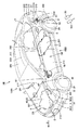
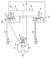
図1から図5を用いて、本発明の実施の形態1に係るハイブリッド車両100について説明する。図1は、本発明の実施の形態1に係るハイブリッド車両100の概略構成を示す斜視図である。
(Embodiment 1)
A
図1において、ハイブリッド車両100は、ボディと外装部品とから形成された車両本体200と、ハイブリッド車両100の進行方向D前方側に設けられた一対の前輪(車輪)2Fと、進行方向D後方側に設けられた後輪(車輪)2Rとを備えている。
In FIG. 1, a
車両本体200は、ハイブリッド車両100の進行方向前方Dに設けられたエンジンコンパートメントERと、このエンジンコンパートメントERに対して進行方向D後方側に隣接する乗員収容室CRと、乗員収容室CRに対して進行方向D後方側に隣接する荷物室LRとを備えている。
The vehicle
そして、車両本体200のボディとしては、たとえば、モノコックボディ(monocoque body)が採用されている。このボディの表面に、複数の外装部品を装着して、車両本体200が構成されている。
For example, a monocoque body is used as the body of the
外装部品としては、たとえば、車両本体200の前方側に設けられたフロントバンパ300と、フロントフェンダ301と、回動可能に設けられたフロントドア312およびリアドア313とを備えている。
As exterior parts, for example, a
また、外装部品としては、エンジンコンパートメントERの上蓋としてのフード307と、リアドア313に対して進行方向D後方側に設けられたリヤフェンダ303と、リヤフェンダ303の下方に設けられたリアバンパ304とを備えている。
The exterior parts include a
そして、乗員収容室CR内の後部座席下に位置する部分には、ガソリン等の液体燃料(第1エネルギ源)が蓄積されるフューエルタンク201が設けられている。また、後部座席よりハイブリッド車両100の後方側には、電力(第2エネルギ源)を充放電可能な2次電池や大容量のキャパシタ等のバッテリBが配置されている。
A
エンジンコンパートメントER内には、トランスアクスルTRと、前輪2Fを駆動する動力を発生する内燃機関としてのエンジン4とを備えている。
The engine compartment ER includes a transaxle TR and an engine 4 serving as an internal combustion engine that generates power for driving the
トランスアクスルTRは、前輪2Fを駆動するモータとして機能したり、発電機として機能する回転電機(モータジェネレータ)MG1,MG2と、昇圧コンバータ20と、インバータ30,40と、プラネタリギヤ等の動力分割機構3とを含む。昇圧コンバータ20は、バッテリBからの電力を昇圧して、インバータ30,40を介して、回転電機MG1,MG2に電力を供給したり、回転電機MG1,MG2によって発電された電力を降圧して、バッテリBに充電したりする。
The transaxle TR functions as a motor that drives the
インバータ30,40は、バッテリBからの直流電力を3相の交流電力に変換して、回転電機MG1,MG2に供給したり、回転電機MG1,MG2が発電した電力を直流電力に変換したりする。
The
乗員収容室CR内には、ECU(Electronic Control Unit)などの制御装置70が設
けられており、インバータ30,40は、この制御装置70からの信号PWMによって駆動する。
A
ハイブリッド車両100の周面のうち、運転席DR側の側面100Aに対して、ハイブリッド車両100の幅方向に対向する側面100Bには、充電・給電部(第2エネルギ源受入部)90と、給油部(第1エネルギ受入部)213とが設けられている。なお、この図1に示す例においては、充電・給電部90と給油部213とが同一の側面100Bに設けられているが、これに限られず、それぞれが異なる側面100A,100Bに設けるようにしてもよい。さらに、充電・給電部90と給油部213との一方をフロントフェンダ301に設け、他方をリヤフェンダ303に配置してもよい。
Of the peripheral surface of the
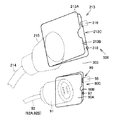
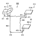
図2は、充電・給電部90および給油部213を示す斜視図である。この図2に示すように、給油部(第1エネルギ源供給部)213は、車両本体200に設けられ、給油コネクタ191のノズル部を受け入れ可能なノズル受入部215と、このノズル受入部215とフューエルタンク201とに接続された接続管214とを備えている。さらに、この給油部213は、リヤフェンダ303に設けられた蓋部材213Aとを備えている。ノズル受入部215は、車両本体200に形成され、リヤフェンダ303に開口部213Bを有する収容室213C内に収容されている。そして、蓋部材213Aは、開口部213Bを
開閉可能なように、リヤフェンダ303に回動可能に設けられている。
FIG. 2 is a perspective view showing the charging /
充電・給電部90は、車両本体200に設けられた挿入部91と、リヤフェンダ303に設けられ、挿入部91を外方に露出したり、車両本体200内に収容したりする蓋部材90Aとを備えている。さらに、充電・給電部90は、挿入部91に接続され、図1に示す回転電機MG1,MG2の各中性点に接続された、配線92A,92Bとを備えている。そして、挿入部91には、コネクタ(第2エネルギ供給部)190が接続可能とされている。この挿入部91は、リヤフェンダ303に形成された開口部90Bを有する収容室90C内に収容されている。蓋部材90Aは、開口部90Bを開閉可能なようにリヤフェンダ303に回動可能に設けられている。
The charging /
そして、ハイブリッド車両100は、蓋部材90Aと蓋部材213Aとの一方が開状態とされたときに、他方を閉状態とする開閉制御機構500を備えている。
The
この開閉制御機構500は、制御装置70と、制御装置70によって駆動が制御され、蓋部材213Aの閉状態を維持するロック機構216と、蓋部材213Aの開閉状態を検知可能なセンサ218と、運転席DRに設けられ、ロック機構216のロック状態を解除して、蓋部材213Aを回動可能とする開操作部217とを備えている。
The opening /
そして、たとえば、給油作業を行う際には、図1に示す開操作部217を操作して、蓋部材213Aのロック状態を解除する。その後、作業者が蓋部材213Aを回動して、ノズル受入部215に給油コネクタ191を挿入して燃料が供給される。給油部213から給油されたガソリンなどの燃料は、接続管214を介して、フューエルタンク201に貯留される。なお、本実施の形態1においては、ガソリンが用いられているが、これに限られず、たとえば、軽油、CNG(Compressed Natural Gas)、水素のいずれでもよい。
For example, when performing a refueling operation, the
さらに、開閉制御機構500は、制御装置70によって駆動が制御され、蓋部材90Aの閉状態を維持するロック機構95と、蓋部材90Aの開閉状態を検知するセンサ97と、運転席DRに設けられ、ロック機構95のロック状態を解除して、蓋部材90Aを回動可能とする開操作部96とを備えている。
Further, the opening /
なお、挿入部91に接続されるコネクタ190としては、充電用のコネクタと、給電用のコネクタと、充電・給電用コネクタのいずれも含む。そして、充電用のコネクタとしては、商用電源(たとえば、日本では単相交流100V)から供給される電力を充電するためのコネクタである。この充電用のコネクタとしては、たとえば、一般の家庭用電源に接続されたコンセントなどが挙げられる。
The
給電用のコネクタは、ハイブリッド車両100からの電力(たとえば、日本では単相交流100V)を外部負荷へ供給するためのコネクタである。さらに、充電・給電用コネクタは、上記充電用コネクタおよび給電用コネクタのいずれの機能をも有するコネクタであり、商用電源から供給される電力を充電可能であるとともに、ハイブリッド車両100からの電力を外部負荷に供給可能なコネクタである。
The power supply connector is a connector for supplying electric power from the hybrid vehicle 100 (for example, single-phase AC 100V in Japan) to an external load. Furthermore, the charging / power feeding connector is a connector having both functions of the charging connector and the power feeding connector, can be charged with power supplied from a commercial power source, and can be supplied with power from the
なお、コネクタ190と充電・給電部90との間における電力に授受方法としては、コネクタ190の一部と充電・給電部90の少なくとも一部とが直接接触する接触型(コンタクティブ)であってもよいし、また、非接触型(インダクティブ)であってもよい。なお、コネクタ190と給油コネクタ191とは、互いに別個独立部材とされている。
In addition, as a method of transmitting and receiving power between the
そして、バッテリBを充電したり、バッテリBに蓄積された電力を外部負荷に供給する際には、まず、開操作部96を操作して、蓋部材90Aのロック状態を解除して、作業者
が蓋部材90Aを回動する。その後に、挿入部91にコネクタ190を接続して、図1に示す回転電機MG1,MG2およびインバータ30,40を介して、バッテリBを充電したり、バッテリBからの電力で外部負荷を充電したりする。
When charging the battery B or supplying the electric power stored in the battery B to the external load, first, the
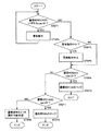
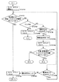
図3は、ロック機構95およびロック機構216の制御フローを示すフロー図である。この図3において、制御装置70は、センサ97、218からの信号に基づいて、各蓋部材90A,213Aの開閉状態を判断する。
FIG. 3 is a flowchart showing a control flow of the
まず、制御装置70は、蓋部材90A,213Aのいずれもが開状態か否かを判断する(STEP1)。そして、蓋部材90A,213Aのいずれも、開状態と判断すると、警告音を発したり、警告ランプを点燈させたりする警告動作を行う。
First, the
その一方で、蓋部材90A,213Aの少なくとも一方が閉状態とされていると判断すると、警告動作が継続しているか否かを判断する(STEP2)。そして、警告動作が継続している場合には、警告動作を中止する(STEP4)。
On the other hand, if it is determined that at least one of the
そして、蓋部材90Aが開状態か否かを判断する(STEP5)。蓋部材90Aが開いていると判断すると、制御装置70は、開操作部217の操作を禁止して、ロック機構216による蓋部材213Aのロック状態を維持させる(STEP6)。なお、開操作部217の操作を禁止する方法としては、たとえば、運転者が開操作部217の操作レバーなどを回動しようとしても、操作レバーが回動しないようにロックしたり、操作レバーを操作したとしても、ロック機構216のロック状態が解除されないようにする方法等が挙げられる。
Then, it is determined whether or not the
その一方で、蓋部材90Aが閉状態であると判断すると、蓋部材213Aが開状態であるか否かを判断する(STEP7)。そして、蓋部材213Aが開状態であると判断すると、蓋部材90Aをロックして、蓋部材90Aの閉状態を維持する(STEP8)。この蓋部材90Aの閉状態を維持する方法としては、ロック機構95が蓋部材90Aをロックし、さらに、開操作部96の操作レバーを運転者が回動操作しようとしても操作レバーが回動しないようにロックされたり、操作レバーを操作したとしても、ロック機構216のロック状態が解除されないようにする方法等が挙げられる。
On the other hand, if it is determined that the
その一方で、蓋部材213Aも閉状態であると判断すると、制御装置70は、開操作部96,217により、蓋部材90Aと蓋部材213Aとを開操作可能とする(STEP9)。なお、この際、蓋部材90Aと蓋部材213Aとの一方を開操作可能となっており、蓋部材90Aと蓋部材213Aのいずれをも開操作することができないようになっている。
On the other hand, when it is determined that the
このように、蓋部材90Aと蓋部材213Aの開閉状態を制御することで、蓋部材90Aと蓋部材213Aのいずれもが開状態となることを抑制することができる。このように、蓋部材213Aと蓋部材90Aとが開状態となることを抑制することで、充電や給油作業を行う作業者が、充電・給電作業と、給油作業を同時に行うことを抑制することができ、充電・給電作業と給油作業とを同時に行うことに起因して、作業ミスが生じることを抑制することができる。
Thus, by controlling the open / closed state of the
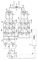
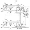
図4は、本発明の実施の形態1によるハイブリッド車両100の概略ブロック図である。この図4を用いて、コネクタ190からの交流電流をバッテリBに充電する方法について説明する。バッテリBの正電極は、正極線PL1に接続され、バッテリBの負電極は、負極線NL1に接続される。コンデンサC1は、正極線PL1と負極線NL1との間に接続される。昇圧コンバータ20は、正極線PL1および負極線NL1と正極線PL2およ
び負極線NL2との間に接続される。コンデンサC2は、正極線PL2と負極線NL2との間に接続される。インバータ30は、正極線PL2および負極線NL2と回転電機MG1との間に接続される。インバータ40は、正極線PL2および負極線NL2と回転電機MG2との間に接続される。
FIG. 4 is a schematic block diagram of
回転電機MG1は、3相コイル11をステータコイルとして備え、回転電機MG2は、3相コイル12をステータコイルとして備える。
The rotating electrical machine MG1 includes a three-
昇圧コンバータ20は、リアクトルL1と、NPNトランジスタQ1,Q2と、ダイオードD1,D2とを含む。
インバータ30は、U相アーム31と、V相アーム32と、W相アーム33とから成る。U相アーム31、V相アーム32、およびW相アーム33は、正極線PL2と負極線NL2との間に並列に設けられる。U相アーム31は、直列接続されたNPNトランジスタQ3,Q4から成り、V相アーム32は、直列接続されたNPNトランジスタQ5,Q6から成り、W相アーム33は、直列接続されたNPNトランジスタQ7,Q8から成る。また、各NPNトランジスタQ3〜Q8のコレクタ−エミッタ間には、エミッタ側からコレクタ側へ電流を流すダイオードD3〜D8がそれぞれ接続されている。
インバータ30の各相アームの中間点は、回転電機MG1に含まれる3相コイル11の各相コイルの各相端に接続されている。すなわち、回転電機MG1は、3相の永久磁石モータであり、U,V,W相の3つのコイルの一端が中性点M1に共通接続されて構成され、U相コイルの他端がNPNトランジスタQ3,Q4の中間点に、V相コイルの他端がNPNトランジスタQ5,Q6の中間点に、W相コイルの他端がNPNトランジスタQ7,Q8の中間点にそれぞれ接続されている。
An intermediate point of each phase arm of
インバータ40は、コンデンサC2の両端にインバータ30と並列に接続される。そして、インバータ40は、U相アーム41と、V相アーム42と、W相アーム43とからなる。U相アーム41、V相アーム42、W相アーム43は、正極線PL2と負極線NL2との間に並列に設けられる。
The
U相アーム41は、直列接続されたNPNトランジスタQ9,Q10から成り、V相アーム42は、直列接続されたNPNトランジスタQ11,Q12から成り、W相アーム43は、直列接続されたNPNトランジスタQ13,Q14から成る。NPNトランジスタQ9〜Q14は、それぞれ、インバータ30のNPNトランジスタQ3〜Q8に相当する。つまり、インバータ40は、インバータ30と同じ構成からなる。そして、NPNトランジスタQ9〜Q14のコレクタ−エミッタ間には、エミッタ側からコレクタ側へ電流を流すダイオードD9〜D14がそれぞれ接続されている。
The
インバータ40の各相アームの中間点は、回転電機MG2に含まれる3相コイル12の各相コイルの各相端に接続されている。すなわち、回転電機MG2も、3相の永久磁石モータであり、U,V,W相の3つのコイルの一端が中性点M2に共通接続されて構成され、U相コイルの他端がNPNトランジスタQ9,Q10の中間点に、V相コイルの他端がNPNトランジスタQ11,Q12の中間点に、W相コイルの他端がNPNトランジスタQ13,Q14の中間点にそれぞれ接続されている。
An intermediate point of each phase arm of
バッテリBは、ニッケル水素またはリチウムイオン等の二次電池から成る。電圧センサー10は、バッテリBから出力されるバッテリ電圧Vbを検出し、その検出したバッテリ電圧Vbを制御装置70へ出力する。システムリレーSR1,SR2は、制御装置70からの信号SEによりオン/オフされる。昇圧コンバータ20は、コンデンサC1から供給
された直流電圧を昇圧してコンデンサC2へ供給する。
The battery B is composed of a secondary battery such as nickel metal hydride or lithium ion.
コンデンサC2は、昇圧コンバータ20からの直流電圧を平滑化し、その平滑化した直流電圧をインバータ30,40へ供給する。
Capacitor C2 smoothes the DC voltage from
インバータ30は、コンデンサC2から直流電圧が供給されると制御装置70からの信号PWM1に基づいて直流電圧を交流電圧に変換して回転電機MG1を駆動する。また、インバータ30は、動力出力装置が搭載されたハイブリッド自動車の回生制動時、回転電機MG1が発電した交流電圧を制御装置70からの信号PWM1に基づいて直流電圧に変換し、その変換した直流電圧をコンデンサC2を介して昇圧コンバータ20へ供給する。
When a DC voltage is supplied from capacitor C2,
インバータ40は、コンデンサC2から直流電圧が供給されると制御装置70からの信号PWM2に基づいて直流電圧を交流電圧に変換して回転電機MG2を駆動する。
When the DC voltage is supplied from the capacitor C2, the
ここで、三相ブリッジ回路から成る各インバータ30,40においては、6個のトランジスタのオン/オフの組合わせは8パターン存在する。その8つのスイッチングパターンのうち2つは相間電圧が零となり、そのような電圧状態は零電圧ベクトルと称される。零電圧ベクトルについては、上アームの3つのトランジスタは互いに同じスイッチング状態(全てオンまたはオフ)とみなすことができ、また、下アームの3つのトランジスタも互いに同じスイッチング状態とみなすことができる。したがって、この図4では、インバータ30の上アームの3つのトランジスタは上アーム30Aとしてまとめて示され、インバータ30の下アームの3つのトランジスタは下アーム30Bとしてまとめて示されている。同様に、インバータ40の上アームの3つのトランジスタは上アーム40Aとしてまとめて示され、インバータ40の下アームの3つのトランジスタは下アーム40Bとしてまとめて示されている。
Here, in each of the
図4に示されるように、零相等価回路は、コネクタ190の電力入力線ACL1,ACL2および配線92A,92Bを介して中性点M1,M2に与えられる単相交流電力を入力とする単相PWMコンバータとみることができる。そこで、インバータ30,40の各々において零電圧ベクトルを変化させ、インバータ30,40を単相PWMコンバータのアームとして動作するようにスイッチング制御することによって、電力入力線ACL1,ACL2から入力される交流電力を直流電力に変換して正極線PL2へ出力することができる。その変換した直流電圧をコンデンサC2を介して昇圧コンバータ20へ供給し、バッテリBに充電する。
As shown in FIG. 4, the zero-phase equivalent circuit has a single-phase AC power input to the neutral points M1 and M2 via the power input lines ACL1 and ACL2 of the
図5は、ハイブリッド車両の概略ブロック図であり、外部充電を説明するブロック図である。このハイブリッド車両100においては、充電・給電部90に接続されるコネクタ190は、バッテリBに充電された電力を外部負荷に供給することができる外部給電用コネクタである。
FIG. 5 is a schematic block diagram of the hybrid vehicle, and is a block diagram for explaining external charging. In this
外部給電用コネクタは、ハイブリッド車両100からの電力(たとえば、日本では、単相交流100V)を外部負荷に供給するためのコネクタである。 The external power supply connector is a connector for supplying electric power from the hybrid vehicle 100 (for example, single-phase AC 100V in Japan) to an external load.
そして、図5において、インバータ30、40は、制御装置70からの信号PWM1、PWM2に応じて、昇圧コンバータ20を介して、バッテリBから供給される直流電力を商用電源用の交流電力に変換して、充電・給電部90から出力可能なように回転電機MG1、MG2を駆動する。
In FIG. 5,
充電・給電部90は、1次コイル51と2次コイル52とを含む。1次コイル51は、回転電機MG1に含まれる3相コイル11の中性点M1と回転電機MG2に含まれる3相
コイル12の中性点M2との間に接続される。そして、充電・給電部90は、回転電機MG1の中性点M1と回転電機MG2の中性点M2との間に生じた交流電圧を商用電源用の交流電圧に変換して充電・給電部90の端子61,62から出力する。
Charging /
なお、上記のように図1から図5に示す例においては、ハイブリッド車両に適用した場合について説明したが、これに限られず、たとえば、燃料電池車両にも適用することができる。 In the example shown in FIGS. 1 to 5 as described above, the case where the present invention is applied to a hybrid vehicle has been described. However, the present invention is not limited thereto, and can be applied to, for example, a fuel cell vehicle.
すなわち、燃料電池車両の場合においても、水素を生成するための燃料と、バッテリBに電力を供給したり、バッテリBに蓄積された電力を外部負荷に供給するため、燃料を供給するコネクタと電気が流れるコネクタとが接続される。 That is, even in the case of a fuel cell vehicle, a fuel supply connector and an electric power supply are provided to supply hydrogen to the battery B and to supply electric power to the battery B or supply electric power stored in the battery B to an external load. Is connected to the connector through which the current flows.
このため、作業者が、燃料の供給作業と充電・給電作業を行う際に、燃料の供給作業と充電・給電作業と作業者が同時に行うことを抑制することができる。 For this reason, when the worker performs the fuel supply work and the charging / power feeding work, it is possible to prevent the worker from simultaneously performing the fuel supply work, the charging / power feeding work, and the worker.
図6は、開閉制御機構の変形例を示す回路図である。この図6に示す例においては、開閉制御機構500Aは、蓋部材213Aを閉状態を維持可能なロック機構220と、このロック機構220にロック状態を解除可能な解除機構229と、蓋部材90Aの閉状態を維持可能なロック機構230と、このロック機構230のロック状態を解除可能な解除機構239とを備えている。蓋部材213Aは、車両本体200に回転可能に設けられており、蓋部材213Aは、コイルバネなどの弾性部材225によって、開くように付勢されている。
FIG. 6 is a circuit diagram showing a modification of the opening / closing control mechanism. In the example shown in FIG. 6, the opening /
そして、ロック機構220は、蓋部材213Aに形成された穴部224内に一部が挿入される鉤部材221と、鉤部材221を付勢する付勢部材222とを備えている。鉤部材221は、車両本体200に回転可能に設けられており、付勢部材222によって、穴部224内に一部が入り込むように付勢されている。
The
この鉤部材221の上面は、湾曲面状に形成されている。そして、蓋部材213Aが開いた状態から閉じるように回動して、蓋部材213Aの端部が鉤部材221の上面に当接すると、鉤部材221は付勢部材222からの付勢力に抗して、蓋部材213Aから退避するように回転する。
The upper surface of the
そして、蓋部材213Aが回動して、鉤部材221の先端部に穴部224が位置することで、鉤部材221の先端部が穴部224内に入り込み、蓋部材213Aが閉じた状態でロックされる。
Then, the
また、同様に、ロック機構230も、蓋部材90Aに形成された穴部234内に先端部が挿入される鉤部材231と、鉤部材231を付勢する付勢部材232とを備えている。鉤部材231は、車両本体200に回転可能に設けられており、付勢部材232によって、穴部234内に先端部入り込むように付勢されている。
Similarly, the
この鉤部材231の上面は、湾曲面状に形成されており、蓋部材90Aが開いた状態から閉じるように回動して、蓋部材90Aの端部が鉤部材231の上面に当接すると、鉤部材231は付勢部材232からの付勢力に抗して、蓋部材90Aから退避するように回転する。
The upper surface of the
そして、蓋部材90Aがさらに回動して、鉤部材231の先端部に穴部234が位置することで、付勢部材232からの付勢力によって、鉤部材231が回転して、鉤部材231の先端部が穴部234内に入り込み、蓋部材90Aが閉じた状態でロックされる。
The
解除機構229は、蓄電器252からの電力によって鉤部材221を付勢部材222の付勢力に抗して、鉤部材221を回転させる電磁石223と、電磁石223と蓄電器252との接続状態を切り替えるスイッチ227とを備えている。
The
電磁石223は、電力が供給されることで、鉤部材221を引き付けて、鉤部材221の先端部が穴部224から抜き出される。これにより、蓋部材213Aのロック状態が解除され、さらに、弾性部材225からの付勢力によって、蓋部材213Aは、半開き状態となる。
When the
また、解除機構239は、蓄電器252からの電力によって鉤部材221を付勢部材222の付勢力に抗して、鉤部材231を回転させる電磁石233と、電磁石233と蓄電器252との接続状態を切り替えるスイッチ237とを備えている。
In addition, the
電磁石233は、電力が供給されることで、鉤部材231を引き付けて、鉤部材231の先端部が穴部234から抜き出される。これにより、蓋部材213Aのロック状態が解除され、さらに、弾性部材235からの付勢力によって、蓋部材213Aは、半開き状態となる。
When the
ここで、蓋部材213Aには、端子部226が設けられており、蓋部材213Aが開くことで、電磁石233と蓄電器252との電気的な接続状態が切断される。これにより、蓋部材213Aが開いた状態で、スイッチ237を接続したとしても、電磁石233に電力は導通されず、蓋部材90Aの閉状態が維持される。そして、蓋部材213Aを開状態から閉状態とすることで、再度、電磁石233の配線と、端子部226とが電気的に接続される。
Here, the
同様に、蓋部材90Aには、端子部236が設けられており、蓋部材90Aが開くことで、電磁石223と蓄電器252との電気的な接続が切断される。これにより、蓋部材90Aが開いた状態で、スイッチ237を接続したとしても、電磁石233に電力が供給されない。これにより、蓋部材90Aの閉状態が維持される。
Similarly, the
なお、ハイブリッド車両100は、蓋部材90Aおよび蓋部材213Aのいずれもが開状態となったときには、警告音を発したり、警告灯を点燈させる警告装置270を備えている。この警告装置270は、警告音を発する音響装置や警告灯を有する警告器260と、この警告器260に供給する電力が蓄積された蓄電器251と、蓄電器251と警告器260との間の接続状態を切り替える切替機構265とを備えている。
The
切替機構265は、蓄電器252および端子部226に接続された電磁石240と、蓄電器252および端子部236に接続された電磁石250と、この電磁石240,250からの付勢力によって、配線261から切り離される金属製の接続片262と、この接続片262を配線261に接続するように接続片262を付勢する弾性部材263とを備えている。
The
ここで、電磁石240は、蓋部材213Aに設けられた端子部226を介して、蓄電器252に接続され、電磁石241は、蓋部材90Aに設けられた端子部236を介して、蓄電器252に接続されている。
Here, the
このため、蓋部材213Aが閉状態のときには、電磁石240と蓄電器252との接続状態は維持され、さらに、蓋部材90Aが閉状態のときには、電磁石241と蓄電器252との接続状態が維持される。そして、電磁石240と電磁石250との少なくとも一方
が蓄電器252に接続されることで、電磁石240と電磁石250との少なくとも一方の電磁力によって、接続片262を配線261から切り離す。
For this reason, when
すなわち、蓋部材90Aと蓋部材213Aとの少なくとも一方が、閉状態とされているときには、警告器260に蓄電器251からの電力が供給されない。その一方で、蓋部材90Aおよび蓋部材213Aのいずれも開状態とされたときには、電磁石240,250から接続片262に電磁力が加えられず、接続片262は、弾性部材263からの付勢力によって配線261に接続される。このように、蓋部材90Aおよび蓋部材213Aのいずれもが開状態となったときには、警告器260に電力が供給され、警告音が鳴ったり、警告ランプが点燈したりする。
That is, when at least one of the
このように、蓋部材90Aおよび蓋部材213Aのいずれもが開状態となることが抑制されているので、充電・給電作業と、給油作業とを作業者が同時に行うことを抑制することができ、作業者の作業ミスの低減を図ることができる。
As described above, since both the
(実施の形態2)
図7から図13を用いて、本発明の実施の形態2について説明する。なお、図7から図13において、上記図1から図12に示された構成と同一または相当する構成については、同一の符号を付してその説明を省略する。
(Embodiment 2)
A second embodiment of the present invention will be described with reference to FIGS. 7 to 13, the same or corresponding components as those shown in FIGS. 1 to 12 are designated by the same reference numerals and the description thereof is omitted.
図7は、ハイブリッド車両100に搭載された開閉制御機構500の概略構成を示す模式図である。この図7に示すように、開閉制御機構500は、給油部213の開口部を開閉する開口部213Bと、充電・給電部90の蓋部材90Aと、蓋部材213Aおよび蓋部材90Aに接続されたワイヤー(連結部材)460とを備えている。
FIG. 7 is a schematic diagram showing a schematic configuration of the opening /
このため、ワイヤー460は、蓋部材213Aと蓋部材90Aとを連動させることができ、ワイヤー460は、蓋部材213Aが開状態とされたときに、蓋部材90Aを閉状態とし、蓋部材90Aが開いたときには、蓋部材213Aを閉状態とする。このため、ワイヤー460によって、蓋部材90Aと蓋部材213Aとが同時に開状態となることを抑制することができる。
For this reason, the
そして、蓋部材213Aおよび蓋部材90Aのいずれもが閉状態とされているときには、ワイヤー460に弛み(延び代)が生じるように、ワイヤー460の長さが調整されている。そして、蓋部材213Aおよび蓋部材90Aの一方が開かれると、ワイヤー460は引っ張られ、ワイヤー460の弛みがなくなり、引張状態となる。このため、蓋部材213Aおよび蓋部材90Aの他方の蓋部材を開状態とすることは困難なものとなっている。このように、蓋部材213Aおよび蓋部材90Aのいずれもが開状態となることを抑制することができるので、作業者が給油作業と充電作業とを同時に行うことを抑制することができる。これにより、作業者による作業ミスの低減を図ることができる。
And when both
なお、この実施の形態2において、蓋部材213Aの開状態とは、給油部213に給油コネクタ191を装着することができる程度に蓋部材213Aが開くことを意味し、蓋部材90Aの開状態とは、充電・給電部90にコネクタ190を装着可能な程度に開くことを意味する。
In the second embodiment, the open state of the
なお、ワイヤー460は、車両本体に回転可能に設けられたローラ470によって、蓋部材213Aから蓋部材90Aにまで案内されている。ここで、ワイヤー460に図8に示すようなテンション機構を設けてもよい。
The
このテンション機構は、一方の端部が車両に固定されたコイルバネ等の弾性部材475
と、弾性部材475の他方の端部に設けられ、ワイヤー460の引張状態に合わせて変位可能に設けられたテンションローラ474とを備えている。
This tension mechanism has an
And a
このテンション機構を備えることで、蓋部材213Aおよび蓋部材90Aのいずれもが閉じられた状態においては、弾性部材475が収縮して、ワイヤー460に弛みが生じることを抑制する。そして、たとえば、蓋部材213Aまたは蓋部材90Aのいずれかが、開かれて、ワイヤー460が引っ張られると、弾性部材475が伸びる。このように、ワイヤー460の引張状態を維持することで、ワイヤー460がローラ470等から外れることを抑制することができる。
By providing this tension mechanism, the
そして、蓋部材213Aおよび蓋部材90Aのいずれもが閉状態の際には、蓋部材213Aおよび蓋部材90Aの一方が開状態となる程度のワイヤー460の延び代を確保することができる。
When both the
図7において、開閉制御機構500は、たとえば、蓋部材213Aを開閉可能状態にすると共に、蓋部材90Aを閉状態にする第1状態と、蓋部材90Aを開閉可能状態にすると共に、蓋部材213Aを閉状態にする第2状態とに切替可能な切替機構420を備えている。この切替機構420は、運転手によって操作され、切替片411および切替片412を含む操作部410と、切替片412と蓋部材90Aとを連結するワイヤー462と、蓋部材213Aと切替片411と連結するワイヤー461とを備えており、切替機構420は、運転者によって操作されることで、蓋部材213Aまたは蓋部材90Aの一方を選択的に開くことを許容する。
In FIG. 7, for example, the opening /
ここで、操作部410は、軸部413を中心に回動可能に設けられており、たとえば、室内に配置されており、たとえば、運転席側のダッシュボード等に設けられている。そして、操作部410は、屈曲するように曲げられており、切替片411と、この切替片411に対して屈曲するように連設する切替片412とを備えている。
Here, the
ここで、切替片411が、ダッシュボードの表面に沿うように変位すると、切替片412は、ダッシュボードの表面から浮き上がるように変位し、切替片412がダッシュボードの表面に沿うように変位すると、切替片411がダッシュボードの表面から浮き上がるように変位する。
Here, when the
そして、蓋部材213Aが閉じられた状態において、運転手等によって、切替片411がONとされて、切替片411がダッシュボードの表面に沿うように切り替えられると、ワイヤー461の蓋部材213A側の端部と切替片411側の端部との間の距離が縮まり、ワイヤー461に弛み(延び代)が生じる。これにより、蓋部材213Aを開くことが可能となる。
When the
その一方で、切替片412が上記のように変位することで、ワイヤー462のうち、切替片412側の接続端部と、蓋部材90A側の接続端部との間の距離が長くなり、ワイヤー462が引張状態となる。このため、蓋部材90Aが開かれることを抑制することができる。このため、切替片411がONとなり、切替片412がOFFとなることで、蓋部材90Aが開くことが抑制され、蓋部材213Aが開くことが許容される。
On the other hand, when the
図9は、切替片411をONとすると共に、切替片412をOFFとして、蓋部材213Aを開いたときの開閉制御機構500を示す模式図である。
FIG. 9 is a schematic diagram showing the opening /
この図9に示すように、切替片411がONとされた状態で蓋部材213Aを開くことで、給油コネクタ191をノズル受入部215に接続することが可能となる。その一方で
、ワイヤー460は、蓋部材213Aが開かれることで引張状態となり、ワイヤー462も、引張状態となることで、蓋部材90Aが開くことが抑制されている。
As shown in FIG. 9, the
図10は、切替片411をOFFとすると共に、切替片412をONとして、蓋部材213Aおよび蓋部材90Aのいずれもが閉じられたときの開閉制御機構500を示す模式図である。この図10に示すように、切替片412がダッシュボードの表面に沿うように切り替えられ、切替片411がダッシュボードの表面から浮き上がるように位置している。
FIG. 10 is a schematic diagram showing the opening /
このように、操作部410を切り替えることで、ワイヤー462の切替片412側の接続端部と、蓋部材90A側の接続端部との間の距離が縮まり、ワイヤー462に弛みが生じる。これにより、蓋部材90Aが開くことが許容される。その一方で、ワイヤー461の切替片411側の接続端部と、蓋部材213A側の接続端部との間の距離が長くなり、ワイヤー461が引張状態となる。これにより、蓋部材213Aが開くことが抑制される。図11は、切替片411をOFFとすると共に、切替片412をONとして、蓋部材90Aを開いた状態における開閉制御機構500の模式図である。
Thus, by switching the
この図11に示すように、蓋部材90Aが開かれると、ワイヤー460は、引張状態となる。これにより、蓋部材213Aが開かれることを抑制することができる。このように、本実施の形態2に係る開閉制御機構500によれば、蓋部材213Aと蓋部材90Aとが同時に開かれることを抑制することができる。
As shown in FIG. 11, when the
図12を用いて、本発明の実施の形態2に係る開閉制御機構500の変形例を示す。この図12に示すように、開閉制御機構500は、開状態とする蓋部材を選択する操作部410と、蓋部材213Aの閉状態をロックするロック機構220と、ロック機構220によるロック状態を解除可能な解除機構229と、蓋部材90Aの閉状態を維持するロック機構230と、ロック機構230によるロック状態を解除可能な解除機構239と、蓄電器252とを備えている。
A modification of the opening /
開閉制御機構500は、開状態の蓋部材213Aを回転駆動して、蓋部材213Aを閉状態とする閉塞機構450と、開状態の蓋部材90Aを回転して、蓋部材90Aを閉状態とする閉塞機構451とを備えている。
The opening /
ロック機構220は、先端部が蓋部材213Aに形成された穴部224に挿入される鉤部材221と、鉤部材221を付勢する付勢部材222とを備えている。付勢部材222は、鉤部材221の先端部が穴部224内に入り込むように、鉤部材221を付勢している。なお、蓋部材213Aは、一方の辺部で軸支されている。穴部224は、蓋部材213Aのうち、上記一方の辺部に対して反対側に辺部に形成されている。
The
ロック機構230は、先端部が蓋部材90Aに形成された穴部234内に挿入される鉤部材231と、鉤部材231を付勢する付勢部材232とを備えている。付勢部材232は、鉤部材231の先端部が穴部234内に入り込むように鉤部材231を付勢している。
The
解除機構229は、電磁石223と、蓋部材90Aに設けられた端子部236とを備えている。ここで、端子部236は、電磁石223と蓄電器252とを電気的に接続する回路内に設けられており、蓋部材90Aが開状態となると電磁石223と蓄電器252との接続状態を切断可能となっている。また、同様に、解除機構239は、電磁石233と、蓋部材213Aが開状態となることで電磁石233と蓄電器252との電気的な接続状態を切断可能な端子部226とを備えている。
The
開閉制御機構500は、警告装置640を備えている。警告装置640は、蓋部材213Aが開いている際に、駆動可能とされた警告部481と、蓋部材90Aが開いているときに駆動可能とされた警告部482とを備えている。さらに、警告装置640は、警告部480および警告部483を含む。
The opening /
ここで、警告部481は、スイッチ441を介して、蓄電器252に接続されている。スイッチ441は、警告部481に接続された配線と蓄電器252に接続された配線とを接続する接続片と、上記各配線同士を接続するように上記接続片を付勢する付勢部材とを備えている。
Here, the
そして、蓋部材213Aには、突起部440が設けられており、この突起部440は、蓋部材213Aが閉状態の際に、接続片を押圧して、警告部481と蓄電器252との間の電気的な接続を切断可能とされている。このため、蓋部材213Aが閉状態の際には、警告部481は駆動しない。
The
その一方で、蓋部材213Aが開状態となると、付勢部材からの付勢力によって、上記接続片は、蓄電器252に接続された配線と、警告部481に接続された配線とを電気的に接続する。これにより、蓋部材213Aが開状態の際には、警告部481が駆動する。
On the other hand, when the
警告部482は、スイッチ443を介して、蓄電器252に接続されている。スイッチ443は、警告部482に接続された配線と、蓄電器252に接続された配線とを接続する接続片と、上記の配線同士を接続するように上記接続片を付勢する付勢部材とを備えている。
The
そして、蓋部材90Aには、突起部442が設けられており、この突起部442は、蓋部材90Aの閉状態の際に、接続片を押圧して、警告部482と蓄電器252との電気的な接続が切断されている。このため、蓋部材90Aが閉状態の際には、警告部482は駆動しない。
The
その一方で、蓋部材90Aが開状態となると、付勢部材からの付勢力によって、上記接続片は、蓄電器252に接続された配線と、警告部482に接続された配線とを電気的に接続する。これにより、蓋部材90Aが開状態の際には、警告部482が駆動する。
On the other hand, when the
このように、この図12に示す例においては、蓋部材213Aおよび蓋部材90Aの少なくとも一方が開状態の際には、警告動作が行われ、運転手や作業者に対して、蓋部材が開いている旨の注意を喚起させることができる。
As described above, in the example shown in FIG. 12, when at least one of the
図13は、操作部410の概略構成を示す模式図である。この図13に示すように、操作部410は、切替スイッチ430を含み、この切替スイッチ430は、切替片438と、この切替片438に対して屈曲するように配置された切替片437と、切替片437と切替片438との連結部に設けられた軸部434とを備えている。ここで、切替スイッチ430は、運転席およびその近傍のダッシュボード等に回転可能に設けられており、軸部434を中心に回転可能に設けられている。
FIG. 13 is a schematic diagram illustrating a schematic configuration of the
ここで、切替片438が選択されてONとなると、電磁石223が駆動して、鉤部材221を穴部224から引き抜く。これにより、蓋部材213Aのロック状態が解除され、蓋部材213Aを開けることができる。その一方で、蓋部材213Aが開くと、端子部226によって、電磁石233と蓄電器252との接続が切断され、蓋部材90Aの閉状態を維持することができる。
Here, when the
そして、切替片437が選択されて、ON状態となると、電磁石233が駆動して、鉤部材231が鉤部材231を穴部234から引き抜く。これにより、蓋部材90Aのロック状態が解除され、蓋部材90Aを開くことができる。そして、蓋部材90Aが開状態となると、電磁石223と蓄電器252とが電気的に切断され、電磁石223が駆動することを防止することができる。これにより、蓋部材213Aの閉状態を維持することができる。
When the
閉塞機構450は、開状態の蓋部材213Aを閉めるように回転させるモータ446を含み、閉塞機構451は、開状態の蓋部材90Aを閉めるように回転させるモータ445を含む。
The
ここで、モータ446は、操作部410によってON/OFFが切り替えられるスイッチ435、および蓋部材213Aの開閉状態によってON/OFFが切り替えられるスイッチ441を介して、蓄電器252に接続されている。
Here, the
そして、モータ445は、操作部410によってON/OFFが切り替えられるスイッチ436、および蓋部材90Aの開閉状態によってON/OFFが切り替えられるスイッチ443を介して、蓄電器252に接続されている。
The
ここで、図12および図13に示すように、警告部480およびモータ446は、蓄電器252に対して直列に接続されており、モータ445と警告部483とは、蓄電器252に対して、直列に接続されている。スイッチ435は、警告部480およびモータ446に接続された配線と、蓄電器252に接続された配線とを接続可能な接続片452、および上記配線同士を接続するように接続片452を付勢する付勢部材454とを備えている。
Here, as shown in FIGS. 12 and 13, the
そして、切替片438には、接続片452を押圧可能な突起部431が形成されており、切替片438側がONとされているときには、接続片452は、突起部431に押圧されることで、上記各配線から離れる。このように、蓋部材213Aのロックを解除するために選択される切替片438が選択されて、ON状態となると、警告部480とモータ446とは、駆動しない。
The
スイッチ436は、警告部483およびモータ445に接続された配線と、蓄電器252に接続された配線とを接続可能な接続片453と、上記配線同士を接続するように接続片453を付勢する付勢部材455とを備えている。なお、接続片453は、切替片437に形成された突起部433によって押圧可能とされている。
The
そして、切替片438が選択されると、切替片437に形成された突起部433は、接続片453から離間して、接続片453は、上記配線同士を接続する。ここで、スイッチ443は、モータ445および警告部483に接続された配線と、蓄電器252に接続された配線とを接続可能な接続片と、上記各配線同士を接続するように接続片を付勢する付勢部材とを含む。この接続片は、蓋部材90Aに形成された突起部442によって押圧されることで、各配線から離間可能とされており、突起部442から押圧されなくなると、各配線同士を接続可能とされている。
When the
このため、切替スイッチ430において、切替片438が選択された状態で、蓋部材90Aが開状態の際には、スイッチ443およびスイッチ436は、ON状態となっており、警告部483およびモータ445には、蓄電器252からの電力が供給される。
Therefore, when the switching
これにより、警告部483による警告動作がなされる。さらに、モータ445は、蓋部材90Aが閉状態となるように駆動する。そして、蓋部材90Aが閉状態となると、スイッチ443がOFFとなり、警告部483および警告部482の駆動が停止する。なお、この際、電磁石223には、電力が供給されておらず、蓋部材90Aが閉状態となると、ロック機構230によって、蓋部材90Aは、ロックされる。
Thereby, a warning operation by the
なお、蓋部材90Aが開状態の際には、切替スイッチ430の切替片438が選択されても、解除機構229は駆動せず、蓋部材213Aのロック状態を維持することができる。これにより、蓋部材90Aが開状態の際に、蓋部材213Aが開けられることは抑制されている。
When the
切替片437が選択されると、切替片438に形成された突起部431は接続片452から離間して、接続片452は、上記各配線同士を電気的に接続する。ここで、スイッチ441は、モータ446および警告部480に接続された配線と、蓄電器252に接続された配線とを接続可能な接続片と、上記各配線同士を接続するように接続片を付勢する付勢部材とを備えている。
When the
このため、切替片437が選択された状態で、蓋部材213Aが開状態の際には、スイッチ441およびスイッチ435は、いずれも、ON状態となり、警告部480およびモータ446が駆動する。これにより、蓋部材213Aは、モータ446によって閉まるように回動され、蓋部材213Aが閉状態となると、ロック機構220によってロックされる。なお、蓋部材213Aが開状態の際には、電磁石223には、電力が供給されず、蓋部材90Aを開状態とすることは抑制されている。
Therefore, when the
さらに、切替スイッチ430において、切替片438および切替片437のいずれも選択されていない状態では、突起部433および突起部431は、いずれも、各接続片453および接続片452から離間しており、スイッチ435およびスイッチ436は、いずれもON状態となっている。
Further, in the state in which neither the
このため、非選択の状態で、蓋部材213Aが開状態の際には、スイッチ441がON状態となり、警告部480およびモータ446が駆動する。そして、モータ446の駆動によって蓋部材213Aが閉状態となる。
For this reason, when
さらに、非選択の状態で、蓋部材90Aが開状態の際には、スイッチ443がON状態となり、警告部483およびモータ445が駆動する。そして、モータ445の駆動によって、蓋部材90Aが閉状態となる。
Further, when the
このように、この図12に示す例においても、蓋部材213Aおよび蓋部材90Aのいずれもが開状態となることを抑制することができる。
As described above, also in the example shown in FIG. 12, it is possible to prevent both the
(実施の形態3)
図14から図23を用いて、本発明の実施の実施の形態3に係る車両に搭載される開閉制御機構500について説明する。なお、図14から図23において、上記図1から図13に示された構成と同一または相当する構成については、同一の符号を付して、その説明を省略する場合がある。
(Embodiment 3)
An opening /
図14は、本発明の実施の形態に係る車両に搭載される開閉制御機構500のブロック図である。この図14に示すように、開閉制御機構500は、蓋部材90Aの開閉状態をセンシングするセンサ97、および蓋部材213Aの開閉状態をセンシング可能なセンサ218を含む検出部と、蓋部材90Aが開状態であることを警告する警告表示642、お
よび蓋部材213Aが開状態であることを警告する警告表示641を含む出力部とを備えている。
FIG. 14 is a block diagram of an opening /
そして、開閉制御機構500は、センサ97およびセンサ218からの開閉信号P1,P2に基づいて、警告表示641および警告表示642を駆動する蓋開閉判定部610を含む制御装置70を備えている。
The open /
開閉制御機構500は、給油コネクタ191が、給油部213のノズル受入部215内に挿入されているか否かをセンシングする挿入センサ601と、充電・給電部90の挿入部91にコネクタ190が装着されているか否かをセンシングする挿入センサ602とを、検出部として含んでいる。
In the opening /
さらに、開閉制御機構500は、開状態の蓋部材213Aを閉状態とするためのモータ603と、開状態の蓋部材213Aを閉状態とするための挿入センサ602とを出力部として備えている。
Further, the opening /
制御装置70は、挿入センサ602からの挿入信号P3および挿入センサ601からの挿入信号P4をに基づいて、充電・給電部90におけるコネクタ190の接続状態および給油部213における給油コネクタ191の接続状態を判定するプラグ挿入判定部620を備える。
Based on the insertion signal P3 from the
そして、制御装置70は、蓋開閉判定部610からの開閉情報P10と、プラグ挿入判定部620からの挿入情報P11とに基づいて、警告表示641,642、挿入センサ602、602および警告装置640などを駆動する駆動制御部630を備えている。
Based on the opening / closing information P10 from the lid opening /
ここで、駆動制御部630は、開閉情報P10および挿入情報P11に基づいて、そのときにおける蓋部材90Aおよび蓋部材213Aの開閉状態およびコネクタ190および給油コネクタ191の着脱状態を判定する初期状態判定部633を含む。
Here, based on the opening / closing information P10 and the insertion information P11, the
そして、たとえば、蓋部材90Aと蓋部材213Aとの少なくとも一方の蓋部材が開状態であると共に、他方が閉状態であって、コネクタ190および給油コネクタ191のいずれも装着されていない場合には、給油作業や充電・給電作業の途中であるのか、または、単に蓋の閉め忘れなのかを見極める必要がある。
For example, when at least one lid member of the
そして、所定の期間、当該蓋部材が開状態が維持され、かつ、給油コネクタ191およびコネクタ190が非接続状態であることが継続されている場合には、単に蓋部材の閉め忘れであると考えることができる。
Then, if the lid member is kept open for a predetermined period and the
そこで、駆動制御部630は、初期状態で1つの蓋部材が開状態で、かつ、この開状態の蓋部材にコネクタが装着されていない状態が所定期間継続しているか否かを判定する所定時間状態判定部631を備えている。
Accordingly, the
その一方で、蓋部材90Aおよび蓋部材213Aのいずれもが開状態であって、いずれにもコネクタ190および給油コネクタ191が装着されていない場合には、蓋部材90Aおよび蓋部材213Aのいずれも閉状態として、給油作業と充電・給電作業が同時に行われることを防止する必要がある。
On the other hand, when both the
さらに、蓋部材90Aおよび蓋部材213Aのいずれも開状態であって、給油コネクタ191が挿入されている場合においても、給油作業と充電・給電作業のいずれもが同時に行われる可能性が高いため、蓋部材90Aを閉じる必要がある。
Furthermore, since both the
また、蓋部材90Aおよび蓋部材213Aのいずれもが開状態であって、コネクタ190が装着されている場合においても、給油作業と充電・給電作業のいずれもが同時に行われる可能性が高いため、蓋部材213Aを閉じる必要がある。
In addition, even when both the
これらの場合には、各状態に合わせて、モータ603,604および警告装置640を駆動する必要がある。
In these cases, it is necessary to drive the
そこで、駆動制御部630は、各状態に合わせて、モータ603,604および警告装置640、さらに、警告表示641および警告表示642を適宜駆動する最終処理部632を備えている。
Therefore, the
この場合、駆動情報P35が初期状態判定部633から最終処理部632に送信され、この駆動情報P35に基づいて、最終処理部632は、各出力部を駆動する。
In this case, drive information P35 is transmitted from the initial
さらに、上記所定時間状態判定部631において、蓋部材の閉め忘れの状態が維持されていると判断された場合においても、所定時間状態判定部631から駆動情報P30が
最終処理部632に送信され、最終処理部632は、この駆動情報P30に基づいて、各出力部を駆動する。
Further, even when the predetermined time
さらに、最終処理部632には、選択された開状態の蓋部材90Aまたは蓋部材213Aを閉状態とする際に、所定時間内に選択された蓋部材90Aまたは蓋部材213Aが閉状態となったかを判定する閉状態判定部634を備えている。
Furthermore, when the selected
すなわち、閉動作を開始した蓋部材90Aまたは蓋部材213Aが所定時間内に、閉状態が完了しない場合には、当該蓋部材と車両の筐体との間に異物が挟まれていることが考えられる。この場合には、閉状態判定部634は、異常発生を周囲に知らせる警告動作を行う。
That is, when the
なお、図15は、開閉制御機構500を構成する各部材を模式的に示す模式図である。この図15に示すように、警告装置640、警告表示641および警告表示642は、運転手から容易に観察可能なように、ダッシュボードおよびその近傍に配置する。
FIG. 15 is a schematic diagram schematically showing each member constituting the opening /
ここで、図16から図23を用いて、各処理について具体的に説明する。
図16は、蓋開閉判定部610における処理のフローを示すフロー図である。この図16に示すように、まず、蓋開閉判定部610は、蓋部材213Aが開状態か否かを判定する(STEP1)。そして、蓋部材213Aが開状態であると判定すると、蓋部材90Aが開状態であるかを判定する(STEP2)。蓋部材90Aが開状態であると判定すると、警告表示641および警告表示642をON状態とする(STEP3)。
Here, each process will be specifically described with reference to FIGS. 16 to 23.
FIG. 16 is a flowchart showing a process flow in the lid opening /
そして、蓋部材213Aおよび蓋部材90Aのいずれもが開状態のときには、コネクタ190および給油コネクタ191が装着されているか否かを判定する(A−2)。
When both the
図17は、初期状態判定部633において、蓋部材90Aおよび蓋部材213Aのいずれも開状態であるときに、コネクタ190および給油コネクタ191が装着されているかを判定するフローを示すフロー図である。
FIG. 17 is a flowchart showing a flow in the initial
この図17に示すように、まず、給油部213に給油コネクタ191が接続されているかを判定する(STEP4)。そして、給油コネクタ191が装着されていると判定した場合には、充電・給電部90にコネクタ190が接続されているかを判定する(STEP
5)。
As shown in FIG. 17, first, it is determined whether or not the
5).
そして、コネクタ190が接続されていないと判定した場合には、蓋部材213Aおよび蓋部材90Aのいずれもが開状態であって、給油部213のみに給油コネクタ191が装着されていることになる。このような場合には、コネクタ190が装着されていない充電・給電部90の蓋部材90Aを閉状態とする処理(B−1)を行う。
When it is determined that the
そして、初期状態判定部633は、上記の駆動情報P35を最終処理部632に送信する。
Then, the initial
図18は、最終処理部632が、蓋部材90Aを閉状態とするためのフローを示すフロー図である。この図18に示すように、最終処理部632は、まず、タイマ280のカウントを開始する(STEP6)。
FIG. 18 is a flowchart showing a flow for the
モータ604を駆動して、蓋部材90Aを閉状態とするように、モータ604を駆動する(STEP7)。
The
そして、所定期間経過するまでに、蓋部材90Aが閉状態となったか否かを判定し、所定期間以内に閉状態となっていないと判定すると、警告装置640を駆動させる。具体的には、まず、蓋部材90Aが開状態であるかを判定する(STEP8)。
Then, it is determined whether or not the
蓋部材90Aが開状態であると判定すると、タイマ280のカウントT2が、予め設定された所定時間T02よりも大きいかを判定する(STEP9)。
If it is determined that the
そして、カウントT2が、所定時間T02以下と判定すると、再度、STEP8に戻り、蓋部材90Aが開状態かどうかを判定する(STEP8)。
When the count T2 is determined to be equal to or less than the predetermined time T02, the process returns to STEP 8 again to determine whether or not the
そして、蓋部材90Aが開状態であると判定すると、再度、タイマ280のカウントT2が所定時間T02より大きいかを判定する(STEP9)。
If it is determined that the
このSTEP9において、カウントT2が所定時間T02よりも大きいと判定すると、蓋部材90Aと車両のボディとの間に異物が挟まれているなどの弊害が生じていることが考えられる。そこで、運転手や作業者に異常事態が発生していることを注意するための警告モードとなるような処理が行われる(E−1)。なお、この図18に示すフロー図には、示されていないが、この場合には、ステップE−1に行く前に、蓋部材90Aに異常発生等の表示を行う処理を加えてもよい。
If it is determined in STEP 9 that the count T2 is greater than the predetermined time T02, it is considered that there is a problem such as a foreign object being sandwiched between the
図19は、最終処理部632が、警告処理を行うときのフローを示すフロー図である。この図19に示すように、最終処理部632が警告処理を行うときには、まず、モータ604およびモータ603の駆動を停止させる(STEP10)。
FIG. 19 is a flowchart showing a flow when the
そして、警告装置640を駆動して、周囲の注意を喚起する(STEP11)。その後
、タイマ280のカウントをリセットして(STEP12)、上記STEP1に戻る(リターン)。
Then, the
そして、上記図18に示すSTEP8において、蓋部材90Aが開状態ではなく、閉状態であると判定した場合には、警告表示642をOFFとする(STEP13)。
Then, in STEP 8 shown in FIG. 18, when it is determined that the
このように、蓋部材90Aが閉状態となると、給油部213からガソリン等を供給する給油作業のみが行われていることなる。このように、正常な状態となると、正常運転モー
ドになるような処理が行われる(C)。
Thus, when
図20は、最終処理部632が、正常モードに切り替えるときの処理のフローを示すフロー図である。この図20に示すように、最終処理部632は、まず、モータ603およびモータ604の駆動を停止させる(STEP14)。
FIG. 20 is a flowchart showing a processing flow when the
そして、警告表示641および警告表示642をOFFとする(STEP15)。そして、警告装置640の駆動を停止させる(STEP16)。そして、タイマ280のカウントをリセットする(STEP17)。そして、上記STEP1に戻る。
Then, the
図17に示す、STEP5にて、充電・給電部90にコネクタ190が接続されていると、判定した場合には、蓋部材213Aおよび蓋部材90Aのいずれも開状態で、給油部213に給油コネクタ191が接続され、さらに、充電・給電部90にコネクタ190が接続されていることになる。
In STEP 5 shown in FIG. 17, when it is determined that the
この場合には、給油作業と、充電・給電作業とが同時になされていると考えられる。さらに、コネクタ190および給油コネクタ191のいずれも接続されているので、いずれの蓋部材90Aおよび蓋部材213Aについても閉めることができない。
In this case, it is considered that the refueling work and the charging / power feeding work are performed at the same time. Furthermore, since both the
そこで、初期状態判定部633は、最終処理部632に対して駆動情報P35を送信して、最終処理部632は、上記のような警告処理を行う(E−1)。
Therefore, the initial
図17に示す(STEP4)において、給油部213に給油コネクタ191が接続されていないと判定すると、初期状態判定部633は、充電・給電部90にコネクタ190が接続されているかを判定する(STEP18)。
In (STEP 4) shown in FIG. 17, when it is determined that the
そして、初期状態判定部633が、充電・給電部90にコネクタ190が接続されていないと判定した場合には、蓋部材90Aおよび蓋部材213Aは、いずれも開状態であって、充電・給電部90のみに、コネクタ190が接続されている状態となっている。
When the initial
このような状態においても、充電・給電作業と、給油作業とが同時に行われるおそれがあるため、蓋部材213Aを閉状態とする処理(B−2)を行う。
Even in such a state, since there is a possibility that the charging / power feeding operation and the refueling operation may be performed at the same time, the process (B-2) for closing the
そこで、初期状態判定部633は、最終処理部632に対して、駆動情報P35が送信する。
Therefore, the initial
図21は、最終処理部632が、蓋部材213Aを閉状態とするためのフローを示すフロー図である。この図21に示すように、最終処理部632は、まず、タイマ280のカウントを開始する(STEP19)。
FIG. 21 is a flowchart showing a flow for the
モータ603を駆動して、蓋部材213Aを閉状態とするように、モータ603を駆動する(STEP20)。
The
そして、所定期間経過するまでに、蓋部材213Aが閉状態となったか否かを判定し、所定期間以内に閉状態となっていないと判定すると、警告装置640を駆動させる。具体的には、まず、蓋部材213Aが開状態であるかを判定する(STEP21)。
Then, it is determined whether or not the
蓋部材213Aが開状態であると判定すると、タイマ280のカウントT2が、予め設定された所定時間T02よりも大きいかを判定する(STEP22)。
If it is determined that the
そしてカウントT2が、所定時間T02以下と判定すると、再度、STEP21に戻り、蓋部材213Aが開状態かどうかを判定する(STEP21)。
When the count T2 is determined to be equal to or less than the predetermined time T02, the process returns to STEP 21 again to determine whether or not the
そして、蓋部材213Aが開状態であると判定すると、再度、タイマ280のカウントT2が所定時間T02より大きいかを判定する(STEP22)。
When it is determined that the
このSTEP22において、カウントT2が所定時間T02よりも大きいと判定すると、蓋部材213Aと車両のボディとの間に異物が挟まれているなどの弊害が生じていることが考えられる。そこで、運転手や作業者に異常事態が発生していることを注意するための警告モードとなるような処理が行われる(E−1)。
If it is determined in STEP 22 that the count T2 is greater than the predetermined time T02, it is considered that there is a problem such as a foreign object being sandwiched between the
そして、(STEP21)において、蓋部材213Aが閉状態であると判定した場合には、警告表示641をOFFとする(STEP23)。この場合には、充電・給電部90において、充電または給電作業のみが行われており、正常に作業が行われていると判断できる。そこで、最終処理部632は、正常処理(C)を行う。
In (STEP 21), when it is determined that the
ここで、上記図17に示す(STEP18)において、充電・給電部90にコネクタ190が接続されているかを判定したときに、コネクタ190が接続されていないと判定した場合には、蓋部材213Aおよび蓋部材90Aが開状態であって、コネクタ190および給油コネクタ191のいずれも接続されていない状態である。
Here, in (STEP 18) shown in FIG. 17 above, when it is determined that the
このような状態では、充電・給電作業と給油作業とが同時に行われるおそれがある。そして、初期状態判定部633は、最終処理部632に対して、蓋部材90Aおよび蓋部材213Aのいずれも、閉じる処理を行うように、駆動情報P35を送信する。
In such a state, there is a possibility that the charging / power feeding operation and the refueling operation are performed simultaneously. Then, the initial
そして、最終処理部632は、蓋部材90Aおよび蓋部材213Aのいずれも、閉じる処理(B−3)を行う。
Then, the
図23は、最終処理部632が、蓋部材90Aおよび蓋部材213Aのいずれも閉状態とするときの処理を示すフロー図である。
FIG. 23 is a flowchart showing processing when the
この図23に示すように、まず、初期状態判定部633は、タイマ280のカウントを開始する(STEP24)。モータ603およびモータ604を駆動する(STEP25、26)。そして、各モータ603およびモータ604を駆動して、各蓋部材90Aおよび蓋部材213Aを閉状態とする際に、蓋部材90Aとボディとの間や蓋部材213Aとボディとの間に異物等が挟まりこんでいる等の弊害が生じているか否かを判定する。
As shown in FIG. 23, first, the initial
具体的には、モータ603およびモータ604の駆動を開始してから、所定期間内に、蓋部材90Aおよび蓋部材213Aが閉状態となっているかを判定し、蓋部材90Aおよび蓋部材213Aのいずれもが閉状態となった場合には、正常処理(C)を行い、蓋部材90Aおよび蓋部材213Aの少なくとも一方が開状態であるときには、警告処理(E−1)を行う。
Specifically, after starting to drive the
具体的には、最終処理部632は、まず蓋部材213Aが開状態であるかを判定する(STEP27)。そして、蓋部材213Aが閉状態であると判定すると、蓋部材90Aが開じ状態であるかを判定する(STEP28)。そして、蓋部材90Aが閉状態であると判定すると、蓋部材90Aおよび蓋部材213Aのいずれもが閉状態であるので、正常処理を行う処理を行う(C)。
Specifically, the
その一方で、上記(STEP28)において、蓋部材90Aが開状態であると判定する
と、最終処理部632は、警告表示641をOFF状態とすると共に、警告表示642をON状態とする(STEP29)。
On the other hand, when it is determined in the above (STEP 28) that the
そして、最終処理部632は、カウンタT2が所定時間T02よりも大きいかを判定する(STEP30)。最終処理部632が、カウンタT2が所定時間T02以下と判定すると、上記(STEP27)に戻る。その一方で、カウントT2が所定時間T02を経過していると、判定した場合には、蓋部材90Aが所定期間の間に閉じることができず、蓋部材90Aとボディとの間に、異物が挟まりこんでいることが考えられる。このため、最終処理部632は、警告処理(E−1)を行う。
Then, the
そして、上記(STEP27)において、蓋部材213Aが開状態であると判定した場合には、最終処理部632は、蓋部材90Aが開状態であるかを判定する(STEP31)。そして、蓋部材90Aが開状態であると、判定すると、警告表示641および警告表示642をON状態とする(STEP32)。
If it is determined in (STEP 27) that the
そして、カウントT2が所定時間T02より大きいと判定すると(STEP30)、警告処理(E−1)を行い、カウントT2が所定時間T02以下と判定すると、再度上記(STEP27)に戻る。 When it is determined that the count T2 is greater than the predetermined time T02 (STEP 30), a warning process (E-1) is performed. When the count T2 is determined to be equal to or less than the predetermined time T02, the process returns to (STEP 27) again.
その一方で、上記(STEP31)において、蓋部材90Aが閉状態であると判定すると、警告表示641をONとし、警告表示642をOFFとする(STEP33)。そして、タイマ280のカウントT2が所定時間T02よりも大きいかを判定する(STEP30)。ここで、カウントT2が所定時間T02より大きいと判定すると、最終処理部632は、警告処理(E−1)を行い、カウントT2が所定時間T02以下と判定すると、上記(STEP27)に戻る。
On the other hand, if it is determined in the above (STEP 31) that the
ここで、図1に示す(STEP2)において、初期状態判定部633が蓋部材90Aは閉状態であると判定した場合には、蓋部材213Aのみが開状態であると判断することができる。
Here, in (STEP 2) shown in FIG. 1, when the initial
この場合には、給油部213に給油コネクタ191が接続されることで、正常に給油作業が行われることになる一方で、給油コネクタ191が所定時間内に挿入されない場合には、蓋部材213Aが開けられた状態で、放置されていることになり、蓋部材213Aを閉める必要が生じる。
In this case, the
そこで、蓋部材213Aおよび蓋部材90Aの開閉状態およびコネクタ190および給油コネクタ191の接続状態を所定期間検出し、蓋部材213Aが開状態、蓋部材90Aが閉状態、コネクタ190および給油コネクタ191が接続されていない状態が所定期間継続されているかを判定する処理を行う(A−1)。
Therefore, the open / closed state of
なお、蓋開閉判定部610は、警告表示641をON状態とし、警告表示642をOFF状態とする(STEP34−1)。
The lid open /
そして、蓋開閉判定部610は、初期状態判定部633に信号を送信し、初期状態判定部633は、所定時間状態判定部631に開閉信号P20を送信する。
Then, lid open /
図22は、蓋部材213Aが開状態であって、蓋部材90Aが閉状態、コネクタ190および給油コネクタ191が接続されていない状態が継続されているかを判定する処理を示すフロー図である。この図22に示すように、まず、所定時間状態判定部631は、タイマ280のカウントを開始する(STEP34)。
FIG. 22 is a flowchart showing a process of determining whether the
そして、給油部213に給油コネクタ191が接続されているか否かを判定する(STEP35)。ここで、給油部213に給油コネクタ191が接続されていると判定すると、タイマ280のカウントをリセットする(STEP36)。
And it is determined whether the
このように、蓋部材213Aのみが開状態であって、給油部213に給油コネクタ191が接続されると、正常に給油作業がなされていると判定することができる。そこで、この場合には、(STEP1)に戻る。
As described above, when only the
その一方で、(STEP35)において、給油部213に給油コネクタ191が接続されていないと判定すると、所定時間状態判定部631は、上記タイマ280のカウントT3が、所定時間T03よりも大きいかを判定する(STEP37)。
On the other hand, when it is determined in (STEP 35) that the
ここで、所定時間状態判定部631が、タイマ280のカウントT3が、所定時間T03以下と判定すると、所定時間状態判定部631は、蓋部材90Aが開状態であるかを判定する(STEP38)。
Here, when the predetermined time
ここで、所定時間状態判定部631は、蓋部材90Aが開かれていないと判定すると、蓋部材213Aが開状態であるかを判定する(STEP39)。ここで、蓋部材90Aが閉状態であると判定できた場合には、蓋部材213Aが開状態、蓋部材90Aが閉状態で、コネクタ190および給油コネクタ191が非接続状態であることが継続している判断することができる。
If the predetermined time
そして、所定時間状態判定部631は、蓋部材213Aが開状態であると判定すると、所定時間状態判定部631は、(STEP35)に戻る。
If the predetermined time
そして、再度、(STEP35)にて、給油部213に給油コネクタ191が接続されているかを判定し、接続されていないと判定すると、所定時間が経過しているかを判定する(STEP37)。
Then, again, in (STEP 35), it is determined whether the
ここで、所定時間状態判定部631が、カウントT3が所定時間T03よりも大きいと判定した場合には、蓋部材213Aが開状態、蓋部材90Aが閉状態、コネクタ190および給油コネクタ191が接続されていない状態が所定期間継続されていることが分かる。
Here, when the predetermined time
この場合には、蓋部材213Aが閉め忘れられていると判断することができるので、蓋部材213Aを閉める処理を行う必要が生じる。
In this case, since it can be determined that the
そこで、所定時間状態判定部631は、タイマ280のカウントをリセットする(STEP40)。そして、所定時間状態判定部631は、最終処理部632に対して、駆動情報を送信する。そして、図21に示すように、蓋部材213Aを閉める処理が最終処理部632にて行われる(B−2)。
Therefore, the predetermined time
ここで、(STEP37)にて、カウントT3が所定時間T03以下と判定すると、蓋部材90Aが開状態であるかを判定する(STEP38)。
Here, if it is determined in (STEP 37) that the count T3 is equal to or less than the predetermined time T03, it is determined whether the
ここで、蓋部材90Aが開状態である場合には、当該処理A−1中において、蓋部材213Aが開いた状態において、作業者等により、蓋部材90Aが別途開かれたと判断することができる。
Here, when the
この場合、まず、所定時間状態判定部631は、警告表示642をON状態とする(STEP41)とし、タイマ280のカウントをリセットする(STEP42)。充電・給電部90に、コネクタ190が接続されているかを判定する(STEP43)。
In this case, first, the
ここで、充電・給電部90にコネクタ190が接続されている場合には、蓋部材213Aを閉状態とする必要がある。そこで、この場合には、最終処理部632にて、図21に示すように、蓋部材213Aを閉状態とする処理(B−2)が行われる。
Here, when the
その一方で、充電・給電部90に、コネクタ190が接続されていないと判定した場合には、蓋部材90Aおよび蓋部材213Aおのいずれもが開状態であって、コネクタ190および給油コネクタ191がいずれにも接続されていなという状態であることが分かる。このような状態においては、作業者によって、充電・給電作業および給油作業が同時に行われるおそれがある。そこで、蓋部材90Aおよび蓋部材213Aのいずれも閉状態とする必要が生じる。そこで、所定時間状態判定部631は、最終処理部632に対して、蓋部材90Aおよび蓋部材213Aのいずれも、閉状態とするように、駆動情報P30を送信し、最終処理部632は、図23に示すように、蓋部材90Aおよび蓋部材213Aのいずれもが閉状態とするための処理(B−3)を行う。
On the other hand, if it is determined that the
ここで、上記(STEP39)において、蓋部材213Aが閉状態であると判定すると、蓋部材213Aおよび蓋部材90Aのいずれも、閉状態となり、開状態であった蓋部材213Aが運転手や作業者によって閉じられたと判断することができる。
Here, when it is determined in the above (STEP 39) that the
そこで、所定時間状態判定部631は、警告表示641をOFFとし(STEP44)し、タイマ280のカウントをリセットする(STEP36)。(STEP1)に戻り、再度蓋部材213Aおよび蓋部材90Aの開閉状態を判定する。
Therefore, the predetermined time
ここで、図16に示す(STEP1)において、蓋部材213Aが閉状態であると判定した場合には、蓋開閉判定部610は、蓋部材90Aが開状態であるかを判定する(STEP45)。ここで、蓋開閉判定部610が、蓋部材90Aが閉状態であると判定した場合には、蓋部材90Aのみが開状態であると判断することができる。
Here, in (STEP 1) shown in FIG. 16, when it is determined that the
このような状態においては、作業者が充電・給電作業を行う途中段階、蓋部材90Aの閉め忘れのいずれかが想定することができる。
In such a state, it can be assumed that the operator is in the middle of performing the charging / power feeding operation or forgetting to close the
そこで、蓋開閉判定部610は、警告表示641をOFF状態とし、警告表示642をON状態とする(STEP45−1)。
Therefore, the lid open /
そこで、蓋開閉判定部610は、初期状態判定部633に開閉情報P10を送信して、初期状態判定部633は、所定時間状態判定部631に所定期間、蓋部材90Aのみが開状態、蓋部材213Aが閉状態、コネクタ190が接続されていない状態が所定期間継続するかを判定するように、駆動情報P20を送信する。
Therefore, the lid open / close determining
図24は、所定期間、蓋部材90Aのみが開状態、蓋部材213Aが閉状態、コネクタ190が接続されていない状態が所定期間継続するかを判定する処理を示すフロー図である。
FIG. 24 is a flowchart showing a process of determining whether only the
この所定時間状態判定部631は、まず、タイマ280のカウントを開始する(STEP46)。
The predetermined time
そして、充電・給電部90にコネクタ190が接続されているか否かを判定する(ST
EP47)。ここで、充電・給電部90にコネクタ190が接続されていると判定すると、タイマ280のカウントをリセットする(STEP48)。このように、蓋部材90Aのみが開状態であって、充電・給電部90にコネクタ190が接続されると、正常に給油作業がなされていると判定することができる。そこで、この場合には、(STEP1)に戻る。
Then, it is determined whether or not the
EP47). If it is determined that the
その一方で、(STEP47)において、充電・給電部90にコネクタ190が接続されていないと判定すると、所定時間状態判定部631は、上記タイマ280のカウントT3が、所定時間T03よりも大きいかを判定する(STEP49)。ここで、所定時間状態判定部631が、タイマ280のカウントT3が、所定時間T03以下と判定すると、所定時間状態判定部631は、蓋部材213Aが開状態であるかを判定する(STEP50)。
On the other hand, if it is determined in (STEP 47) that the
ここで、所定時間状態判定部631は、蓋部材213Aが開かれていないと判定すると、蓋部材90Aが開状態であるかを判定する(STEP51)。ここで、蓋部材90Aが開状態であると判定できた場合には、蓋部材90Aが開状態、蓋部材213Aが閉状態で、コネクタ190および給油コネクタ191が非接続状態であることが継続している判断することができる。
Here, if it is determined that the
そして、所定時間状態判定部631は、蓋部材90Aが開状態であると判定すると、所定時間状態判定部631は、(STEP47)に戻る。そして、再度、(STEP47)にて、充電・給電部90にコネクタ190が接続されているかを判定し、接続されていないと判定すると、所定時間が経過しているかを判定する(STEP49)。
If the predetermined time
ここで、所定時間状態判定部631が、カウントT3が所定時間T03よりも大きいと判定した場合には、蓋部材90Aが開状態、蓋部材213Aが閉状態、コネクタ190および給油コネクタ191が接続されていない状態が所定期間継続されていることが分かる。
Here, when the predetermined time
この場合には、蓋部材90Aを閉め忘れていると判断することができるので、蓋部材90Aを閉める処理を行う必要が生じる。そこで、所定時間状態判定部631は、タイマ280のカウントをリセットする(STEP52)。そして、所定時間状態判定部631は、最終処理部632に対して、駆動情報を送信する。そして、図18に示すように、蓋部材90Aを閉める処理が最終処理部632にて行われる(B−1)。
In this case, since it can be determined that the
ここで、(STEP49)にて、カウントT3が所定時間T03以下と判定すると、蓋部材213Aが開状態であるかを判定する。ここで、蓋部材213Aが開状態である場合には、当該処理A−1中において、蓋部材90Aが開いた状態において、作業者等により、蓋部材213Aが別途開かれたと判断することができる。
Here, if it is determined in (STEP 49) that the count T3 is equal to or less than the predetermined time T03, it is determined whether or not the
この場合、まず、所定時間状態判定部631は、警告表示641をON状態とする(STEP53)とし、タイマ280のカウントをリセットする(STEP54)。給油部213に、給油コネクタ191が接続されているかを判定する(STEP55)。
In this case, first, the
ここで、給油部213に給油コネクタ191が接続されている場合には、蓋部材90Aを閉状態とする必要がある。そこで、この場合には、最終処理部632にて、図18に示すように、蓋部材90Aを閉状態とする処理(B−1)が行われる。
Here, when the
その一方で、給油部213に、給油コネクタ191が接続されていないと判定した場合には、蓋部材90Aおよび蓋部材213Aおのいずれもが開状態であって、コネクタ19
0および給油コネクタ191がいずれにも接続されていなという状態であることが分かる。このような状態においては、作業者によって、充電・給電作業および給油作業が同時に行われるおそれがある。そこで、蓋部材90Aおよび蓋部材213Aのいずれも閉状態とする必要が生じる。そこで、所定時間状態判定部631は、最終処理部632に対して、蓋部材90Aおよび蓋部材213Aのいずれも、閉状態とするように、駆動情報P30を送信し、最終処理部632は、図23に示すように、蓋部材90Aおよび蓋部材213Aのいずれもが閉状態とするための処理(B−3)を行う。
On the other hand, if it is determined that the
It can be seen that 0 and the
ここで、上記(STEP51)において、蓋部材90Aが閉状態であると判定すると、蓋部材213Aおよび蓋部材90Aのいずれも、閉状態となり、開状態であった蓋部材213Aが運転手や作業者によって閉じられたと判断することができる。
Here, if it is determined in the above (STEP 51) that the
そこで、所定時間状態判定部631は、警告表示642をOFFとし(STEP56)し、タイマ280のカウントをリセットする(STEP48)。そして、(STEP1)に戻る。
Accordingly, the predetermined time
ここで、上記図16に示す(STEP45)において、蓋部材90Aが閉状態であると、蓋開閉判定部610が判定すると、蓋部材90Aおよび蓋部材213Aのいずれも閉状態であるので、再度、(STEP1)に戻る。
Here, in (STEP 45) shown in FIG. 16 above, when the lid open / close determining
このように開閉制御機構500を備えた車両においては、給油作業と、充電・給電作業とが同時に行われることを抑制することができる。
In the vehicle including the opening /
以上のように本発明の実施の形態について説明を行なったが、今回開示された実施の形態はすべての点で例示であって制限的なものではないと考えられるべきである。本発明の範囲は特許請求の範囲によって示され、特許請求の範囲と均等の意味および範囲内でのすべての変更が含まれることが意図される。さらに、上記数値などは、例示であり、上記数値および範囲にかぎられない。 Although the embodiment of the present invention has been described above, it should be considered that the embodiment disclosed this time is illustrative and not restrictive in all respects. The scope of the present invention is defined by the terms of the claims, and is intended to include any modifications within the scope and meaning equivalent to the terms of the claims. Furthermore, the above numerical values are examples, and are not limited to the above numerical values and ranges.
本発明に係る車両は、複数種類のエネルギ源が供給される車両に好適である。 The vehicle according to the present invention is suitable for a vehicle to which a plurality of types of energy sources are supplied.
2F 前輪、3 動力分割機構、4 エンジン、10 電圧センサー、20 昇圧コンバータ、30,40 インバータ、61,62 端子、70 制御装置、90 充電・給電部、90C 収容室、95 ロック機構、96,217 開操作部、97 センサ、100 ハイブリッド車両、100A,100B 側面、190 コネクタ、191 給油コネクタ、200 車両本体、201 フューエルタンク、213 給油部、213A 蓋部材、213B 開口部、213C 収容室、214 接続管、215 ノズル受入部、216 ロック機構、217 開操作部、218 センサ、220,230 ロック機構、221,231 鉤部材、222,232,454,455 付勢部材、223,233,240,250 電磁石、224,234 穴部、225,235,475 弾性部材、226,236 端子部、227,237,435,436,441,443 スイッチ、229,239 解除機構、251,252 蓄電器、260 警告器、261 配線、262,452,453,453 接続片、263 弾性部材、265 切替機構、270 警告装置、280 タイマ、300 フロントバンパ、301 フロントフェンダ、303 リヤフェンダ、304 リアバンパ、307 フード、312 フロントドア、313 リアドア、410 操作部、411,412,437,438 切替片、413,434 軸部、420,430 切替スイッチ、431,433,440,442 突起部、445,446 モータ、450,451 閉塞機構、460,461,462 ワイヤー、470 ローラ、474 テンションローラ、480,481,482,483 警告部、500,500A 開閉制御機構、601,602 挿入センサ、603,604 モータ、610 蓋開閉判定部、620 プラグ挿入判定部、630 駆動制御部、631 所定時間状態判定部、632 最終処理部、633 初期状態判定部、634 閉状態判定部、641,642 警告表示。 2F front wheel, 3 power split mechanism, 4 engine, 10 voltage sensor, 20 boost converter, 30, 40 inverter, 61, 62 terminal, 70 control device, 90 charging / feeding unit, 90C accommodation room, 95 lock mechanism, 96, 217 Open operation part, 97 sensor, 100 hybrid vehicle, 100A, 100B side face, 190 connector, 191 oil supply connector, 200 vehicle body, 201 fuel tank, 213 oil supply part, 213A lid member, 213B opening part, 213C accommodation chamber, 214 connection pipe 215 Nozzle receiving portion, 216 lock mechanism, 217 opening operation portion, 218 sensor, 220, 230 lock mechanism, 221, 231 scissors member, 222, 232, 454, 455 biasing member, 223, 233, 240, 250 electromagnet, 224, 234 hole 225, 235, 475 elastic member, 226, 236 terminal part, 227, 237, 435, 436, 441, 443 switch, 229, 239 release mechanism, 251, 252 battery, 260 warning device, 261 wiring, 262, 452, 453 , 453 connection piece, 263 elastic member, 265 switching mechanism, 270 warning device, 280 timer, 300 front bumper, 301 front fender, 303 rear fender, 304 rear bumper, 307 hood, 312 front door, 313 rear door, 410 operation unit, 411 412, 437, 438 Switching piece, 413, 434 Shaft, 420, 430 Changeover switch, 431, 433, 440, 442 Protrusion, 445, 446 Motor, 450, 451 Closure mechanism, 460, 461, 462 Wire 470 roller, 474 tension roller, 480, 481, 482, 483 warning unit, 500, 500A open / close control mechanism, 601, 602 insertion sensor, 603, 604 motor, 610 lid open / close determination unit, 620 plug insertion determination unit, 630 drive Control unit, 631 Predetermined time state determination unit, 632 Final processing unit, 633 Initial state determination unit, 634 Closed state determination unit, 641, 642 Warning display.
Claims (13)
前記第1エネルギ源を蓄積可能な第1蓄積部と、
第1エネルギ供給部が着脱可能に接続され、前記第1エネルギ源が供給される第1エネルギ受入部と、
前記第1エネルギ受入部を収容する第1収容室の開口部を開閉可能とする第1蓋部材と、
前記第1エネルギ受入部に接続され、前記第1エネルギ受入部に供給された前記第1エネルギ源を前記第1蓄積部に導く第1接続部と、
前記第1エネルギ源と異なる第2エネルギ源によって駆動される第2駆動部と、
前記第2エネルギ源を蓄積する第2蓄積部と、
第2エネルギ供給部が着脱可能に接続され、前記第2エネルギ源が供給される第2エネルギ受入部と、
前記第2エネルギ受入部を収容する第2収容室の開口部を開閉可能とする第2蓋部材と、
前記第2エネルギ受入部に接続され、前記第2エネルギ受入部に供給された前記第2エネルギ源を前記第2蓄積部に導く第2接続部と、
前記第1蓋部材と前記第2蓋部材との一方が開状態とされたときに、他方を閉状態に維持する開閉制御機構と、
を備えた、車両。 A first drive unit driven by a first energy source;
A first storage unit capable of storing the first energy source;
A first energy receiving unit to which a first energy supply unit is detachably connected, and the first energy source is supplied;
A first lid member capable of opening and closing an opening of a first storage chamber that houses the first energy receiving portion;
A first connecting portion connected to the first energy receiving portion and guiding the first energy source supplied to the first energy receiving portion to the first storage portion;
A second drive unit driven by a second energy source different from the first energy source;
A second storage section for storing the second energy source;
A second energy receiving unit to which a second energy supply unit is detachably connected and to which the second energy source is supplied;
A second lid member capable of opening and closing the opening of the second storage chamber for storing the second energy receiving portion;
A second connecting part connected to the second energy receiving part and guiding the second energy source supplied to the second energy receiving part to the second storage part;
An opening / closing control mechanism that maintains one of the first lid member and the second lid member in a closed state when one of the first lid member and the second lid member is in an open state;
With a vehicle.
前記第1蓋部材の開閉状態を検出する第1検出部と、
前記第2蓋部材の開閉状態を検出する第2検出部と、
前記第1蓋部材を閉状態に維持する第1ロック部と、
前記第2蓋部材を閉状態に維持する第2ロック部と、
前記第1ロック部による前記第1蓋部材の閉状態を解除可能な第1解除部と、
前記第2ロック部による前記第2蓋部材の閉状態を解除可能な第2解除部と、
前記第1検出部が前記第1蓋部材の開状態を検出したときに、前記第2解除部の駆動を禁止し、前記第2検出部が前記第2蓋部材の開状態を検出したときに、前記第1解除部の駆動を禁止する制御部と含む、請求項1に記載の車両。 The opening / closing control mechanism includes:
A first detector for detecting an open / closed state of the first lid member;
A second detector for detecting an open / closed state of the second lid member;
A first lock portion for maintaining the first lid member in a closed state;
A second lock portion for maintaining the second lid member in a closed state;
A first release part capable of releasing the closed state of the first lid member by the first lock part;
A second release part capable of releasing the closed state of the second lid member by the second lock part;
When the first detection unit detects the open state of the first lid member, the second release unit is prohibited from being driven, and when the second detection unit detects the open state of the second lid member The vehicle according to claim 1, further comprising a control unit that prohibits driving of the first release unit.
前記第1蓄積部は、前記液体状の燃料を蓄積する燃料タンクとされ、
前記第1接続部は、前記液体状の燃料を前記第1エネルギ受入部から前記燃料タンクに導く管路とされ、
前記第2エネルギ源は電力とされ、
前記第2蓄積部は、直流電力として、前記第2エネルギ源を蓄積する蓄電器とされ、
前記第2接続部は、電力が流通する配線とされた、
請求項1または請求項2に記載の車両。 The first energy source is fuel;
The first accumulation unit is a fuel tank that accumulates the liquid fuel,
The first connection portion is a conduit that guides the liquid fuel from the first energy receiving portion to the fuel tank,
The second energy source is electric power;
The second storage unit is a battery that stores the second energy source as DC power,
The second connection portion is a wiring through which power flows.
The vehicle according to claim 1 or claim 2.
前記回転電機は、第1多相巻線と該第1多相巻線の第1中性点とを有する第1回転電機と、第2多相巻線と該第2多相巻線の第2中性点とを有する第2回転電機とを含み、
前記第2接続部は、前記第1中性点に接続された第1配線と、前記第2中性点に接続された第2配線とを含み、
前記蓄電器からの直流電力としての前記第2エネルギ源を交流電力としての前記第2エネルギ源に変換して前記第1回転電機に供給する第1インバータと、
前記蓄電器からの直流電力としての前記第2エネルギ源を交流電力としての前記第2エネルギ源に変換して前記第2回転電機に供給する第2インバータと、
前記第1および第2インバータを制御するインバータ制御部とをさらに備え、
インバータ制御部は、前記第2接続部から前記第1および第2中性点に与えられる交流電力を直流電力に変換して、前記蓄電器に供給するように前記第1および第2インバータを制御する、請求項3に記載の車両。 The second drive unit is a rotating electrical machine driven by the second energy source as AC power,
The rotating electrical machine includes a first rotating electrical machine having a first multiphase winding and a first neutral point of the first multiphase winding, a second multiphase winding, and a second multiphase winding. A second rotating electrical machine having two neutral points,
The second connection portion includes a first wiring connected to the first neutral point, and a second wiring connected to the second neutral point,
A first inverter that converts the second energy source as DC power from the capacitor into the second energy source as AC power and supplies the second energy source to the first rotating electrical machine;
A second inverter that converts the second energy source as DC power from the capacitor into the second energy source as AC power and supplies the second energy source to the second rotating electrical machine;
An inverter control unit for controlling the first and second inverters;
The inverter control unit controls the first and second inverters so as to convert AC power given from the second connection unit to the first and second neutral points into DC power and supply the DC power to the battery. The vehicle according to claim 3.
前記回転電機は、第1多相巻線と該第1多相巻線の第1中性点とを有する第1回転電機と、第2多相巻線と該第2多相巻線の第2中性点とを有する第2回転電機とを含み、
前記第2接続部は、前記第1中性点に接続された第1配線と、前記第2中性点に接続された第2配線とを含み、
前記蓄電器からの直流電力としての前記第2エネルギ源を交流電力としての前記第2エネルギ源に変換して前記第1回転電機に供給する第1インバータと、
前記蓄電器からの直流電力としての前記第2エネルギ源を交流電力としての前記第2エネルギ源に変換して前記第2回転電機に供給する第2インバータと、
前記第1および前記第2インバータを制御するインバータ制御部とをさらに備え、
前記インバータ制御部は、前記蓄電器から前記第1インバータおよび前記第2インバータに供給される直流電力を交流電力に変換して、前記第2接続部から外部負荷に供給するように前記第1インバータおよび前記第2インバータを制御する、請求項3に記載の車両。 The second drive unit is a rotating electrical machine driven by the second energy source as AC power,
The rotating electrical machine includes a first rotating electrical machine having a first multiphase winding and a first neutral point of the first multiphase winding, a second multiphase winding, and a second multiphase winding. A second rotating electrical machine having two neutral points,
The second connection portion includes a first wiring connected to the first neutral point, and a second wiring connected to the second neutral point,
A first inverter that converts the second energy source as DC power from the capacitor into the second energy source as AC power and supplies the second energy source to the first rotating electrical machine;
A second inverter that converts the second energy source as DC power from the capacitor into the second energy source as AC power and supplies the second energy source to the second rotating electrical machine;
An inverter control unit for controlling the first and second inverters;
The inverter control unit converts the DC power supplied from the capacitor to the first inverter and the second inverter into AC power, and supplies the AC power to the external load from the second connection unit. The vehicle according to claim 3, wherein the vehicle controls the second inverter.
前記第1蓋部材および前記第2蓋部材の一方が開状態となると、前記連結部材に、他方の蓋部材を閉じる張力が生じる、請求項1から請求項5のいずれかに記載の車両。 The opening / closing control mechanism includes a connecting member that connects the first lid member and the second lid member;
The vehicle according to any one of claims 1 to 5, wherein when one of the first lid member and the second lid member is in an open state, tension is generated in the connecting member to close the other lid member.
前記操作機構は、使用者によって切替操作可能な操作部と、前記操作部および前記第1蓋部材を連結する第1操作用連結部材と、前記操作部および前記第2蓋部材を連結する第2操作用連結部材とを含み、
前記操作機構は第1状態とされることで、前記第1操作用連結部材に延び代を設けて、前記第1蓋部材を開閉可能とすると共に、前記第2操作用連結部材の延び代を低減させて、前記第2蓋部材を閉状態とし、
前記操作機構は第2状態とされることで、前記第1操作用連結部材の延び代を低減して、前記第2蓋部材を閉状態とすると共に、前記第2操作用連結部材に延び代を設けて、前記第2蓋部材を開閉可能とする、請求項1から請求項7のいずれかに記載の車両。 The open / close control mechanism makes the first lid member openable and closable, makes the second lid member closed, and makes the second lid member openable and closable. Including an operation mechanism capable of switching to a second state in which the lid member is closed;
The operation mechanism includes an operation unit that can be switched by a user, a first operation coupling member that couples the operation unit and the first lid member, and a second that couples the operation unit and the second lid member. A connecting member for operation,
When the operation mechanism is in the first state, an extension margin is provided in the first operation connecting member so that the first lid member can be opened and closed, and an extension margin of the second operation connecting member is provided. To reduce the second lid member to a closed state,
When the operation mechanism is in the second state, the extension margin of the first operation connection member is reduced, the second lid member is closed, and the extension margin of the second operation connection member is extended. The vehicle according to claim 1, wherein the second lid member can be opened and closed.
前記第1操作用連結部材は、前記回転部材のうち、前記軸部から離れた位置に接続され、前記第2操作用連結部材は、前記回転部材のうち、前記軸部に対して、前記第1操作用連結部が接続された部分と反対側に位置する部分に接続された、請求項8に記載の車両。 The operation unit includes a rotation member that is rotatably provided, and a shaft portion that rotatably supports the rotation member,
The first operation connecting member is connected to a position apart from the shaft portion of the rotating member, and the second operation connecting member is connected to the shaft portion of the rotating member with respect to the shaft portion. The vehicle according to claim 8, wherein the vehicle is connected to a portion located opposite to the portion to which the one operation connecting portion is connected.
前記第1エネルギ源を蓄積可能な第1蓄積部と、
第1エネルギ供給部が着脱可能に接続され、前記第1エネルギ源が供給される第1エネルギ受入部と、
前記第1エネルギ受入部を収容する第1収容室の開口部を開閉可能とする第1蓋部材と、
前記第1エネルギ受入部に接続され、前記第1エネルギ受入部に供給された前記第1エネルギ源を前記第1蓄積部に導く第1接続部と、
前記第1エネルギ源と異なる第2エネルギ源によって駆動される第2駆動部と、
前記第2エネルギ源を蓄積する第2蓄積部と、
第2エネルギ供給部が着脱可能に接続され、前記第2エネルギ源が供給される第2エネルギ受入部と、
前記第2エネルギ受入部を収容する第2収容室の開口部を開閉可能とする第2蓋部材と、
前記第2エネルギ受入部に接続され、前記第2エネルギ受入部に供給された前記第2エネルギ源を前記第2蓄積部に導く第2接続部と、
前記第1蓋部材および前記第2蓋部材との開閉制御を行う開閉制御装置と、
警告動作を行う警告部を含む出力部とを備え、
前記開閉制御装置は、前記第1蓋部材および前記第2蓋部材の開閉状態を判定する蓋開閉判定部と、前記蓋開閉判定部からの開閉情報に基づいて、前記出力部を駆動する出力部駆動部とを含み、
前記出力部駆動部は、前記第1蓋部材および前記第2蓋部材の少なくとも一方が開状態のときに、前記警告部を駆動し、前記第1蓋部材および第2蓋部材のいずれもが閉状態となると、前記警告部の駆動を停止する、車両。 A first drive unit driven by a first energy source;
A first storage unit capable of storing the first energy source;
A first energy receiving unit to which a first energy supply unit is detachably connected, and the first energy source is supplied;
A first lid member capable of opening and closing an opening of a first storage chamber that houses the first energy receiving portion;
A first connecting portion connected to the first energy receiving portion and guiding the first energy source supplied to the first energy receiving portion to the first storage portion;
A second drive unit driven by a second energy source different from the first energy source;
A second storage section for storing the second energy source;
A second energy receiving unit to which a second energy supply unit is detachably connected and to which the second energy source is supplied;
A second lid member capable of opening and closing the opening of the second storage chamber for storing the second energy receiving portion;
A second connecting part connected to the second energy receiving part and guiding the second energy source supplied to the second energy receiving part to the second storage part;
An opening / closing control device for controlling opening / closing of the first lid member and the second lid member;
An output unit including a warning unit for performing a warning operation,
The open / close control device includes a lid open / close determining unit that determines open / closed states of the first lid member and the second lid member, and an output unit that drives the output unit based on open / close information from the lid open / close determining unit. Including a drive unit,
The output unit driving unit drives the warning unit when at least one of the first lid member and the second lid member is open, and both the first lid member and the second lid member are closed. A vehicle that stops driving the warning unit when the vehicle enters a state.
前記開閉制御装置は、前記第1エネルギ受入部における前記第1エネルギ供給部の接続状態、および前記第2エネルギ受入部おける前記第2エネルギ供給部の接続状態を判定し、前記出力部駆動部に接続情報を送る接続状態判定部を含み、
前記出力部駆動部は、前記第1蓋部材および前記第2蓋部材が開状態であって、前記第1エネルギ受入部に前記第1エネルギ供給部が接続されておらず、前記第2エネルギ受入部に前記第2エネルギ供給部が接続されていないときに、前記第1および第2蓋駆動部を駆動し、
前記出力部駆動部は、前記第1蓋部材および前記第2蓋部材が開状態であって、前記第1エネルギ受入部に前記第1エネルギ供給部が接続されておらず、前記第2エネルギ受入部に前記第2エネルギ供給部が接続されているときに、前記第1蓋駆動部を駆動し、
前記出力部駆動部は、前記第1蓋部材および前記第2蓋部材が開状態であって、前記第1エネルギ受入部に前記第1エネルギ供給部が接続されており、前記第2エネルギ受入部に前記第2エネルギ供給部が接続されていないときに、前記第2蓋駆動部を駆動する、請求項10に記載の車両。 The output unit is configured to drive the first lid member in an open state to be in a closed state, and to drive the second lid member in an open state to be in a closed state. Including
The opening / closing control device determines a connection state of the first energy supply unit in the first energy reception unit and a connection state of the second energy supply unit in the second energy reception unit, and supplies the output unit drive unit with the connection state. Including a connection state determination unit for sending connection information;
In the output unit drive unit, the first lid member and the second lid member are in an open state, the first energy supply unit is not connected to the first energy receiving unit, and the second energy receiving unit is not connected. Driving the first and second lid driving units when the second energy supply unit is not connected to the unit,
In the output unit drive unit, the first lid member and the second lid member are in an open state, the first energy supply unit is not connected to the first energy receiving unit, and the second energy receiving unit is not connected. Driving the first lid driving unit when the second energy supply unit is connected to the unit,
In the output unit driving unit, the first lid member and the second lid member are in an open state, the first energy supply unit is connected to the first energy receiving unit, and the second energy receiving unit The vehicle according to claim 10, wherein the second lid drive unit is driven when the second energy supply unit is not connected to the vehicle.
前記出力部は、開状態の前記第1蓋部材を駆動して閉状態とする第1蓋駆動部、および開状態の前記第2蓋部材を駆動して閉状態とする第2蓋駆動部を含み、
前記開閉制御装置は、前記第1エネルギ受入部における前記第1エネルギ供給部の接続状態、および前記第2エネルギ受入部おける前記第2エネルギ供給部の接続状態を判定し、前記出力部駆動部に接続情報を送る接続状態判定部を含み、
前記出力部駆動部は、前記第1蓋部材が開状態、前記第2蓋部材が閉状態、および前記第1エネルギ受入部に前記第1エネルギ供給部が接続されていない状態が所定期間継続したときに、前記第1蓋駆動部を駆動し、
前記出力部駆動部は、前記第2蓋部材が開状態、前記第1蓋部材が閉状態、および前記第2エネルギ受入部に前記第2エネルギ供給部が接続されていない状態が所定期間継続したときに、前記第2蓋駆動部を駆動する、請求項10または請求項11に記載の車両。 The opening / closing control device measures a period of the open state of the first lid member, and sends the measured period as first measurement information to the output unit driving unit, and an opening of the second lid member. A second measuring unit that measures a period of the state and sends the measured period to the output unit driving unit as second measurement information;
The output unit includes: a first lid driving unit that drives the first lid member in an open state to be in a closed state; and a second lid driving unit that drives the second lid member in an open state to be in a closed state. Including
The opening / closing control device determines a connection state of the first energy supply unit in the first energy reception unit and a connection state of the second energy supply unit in the second energy reception unit, and supplies the output unit drive unit with the connection state. Including a connection state determination unit for sending connection information;
In the output unit driving unit, the first lid member is open, the second lid member is closed, and the first energy supply unit is not connected to the first energy receiving unit for a predetermined period. Sometimes, the first lid driving unit is driven,
In the output unit driving unit, the second lid member is open, the first lid member is closed, and the second energy supply unit is not connected to the second energy receiving unit for a predetermined period. The vehicle according to claim 10 or 11, wherein the second lid driving unit is sometimes driven.
前記出力部駆動部は、前記第1駆動部の駆動時間が所定時間より長くなると、前記第1駆動部の駆動を停止して、前記警告部を駆動し、
前記出力部駆動部は、前記第2駆動部の駆動時間が所定時間より長くなると、前記第2駆動部の駆動を停止して、前記警告部を駆動する、請求項11または請求項12に記載の車両。 The opening / closing control device measures a driving time of the first lid driving unit, sends the driving time as third measurement information to the output unit driving unit, and a driving time of the second lid driving unit. And a fourth measuring unit that sends the driving time to the output unit driving unit as the fourth measurement information,
When the driving time of the first driving unit becomes longer than a predetermined time, the output unit driving unit stops driving the first driving unit and drives the warning unit,
13. The output unit drive unit according to claim 11 or 12, wherein when the drive time of the second drive unit becomes longer than a predetermined time, the output unit drive unit stops driving the second drive unit and drives the warning unit. Vehicle.
Priority Applications (1)
| Application Number | Priority Date | Filing Date | Title |
|---|---|---|---|
| JP2009184679A JP5251783B2 (en) | 2007-08-10 | 2009-08-07 | Open / close notification device and vehicle |
Applications Claiming Priority (3)
| Application Number | Priority Date | Filing Date | Title |
|---|---|---|---|
| JP2007209859 | 2007-08-10 | ||
| JP2007209859 | 2007-08-10 | ||
| JP2009184679A JP5251783B2 (en) | 2007-08-10 | 2009-08-07 | Open / close notification device and vehicle |
Related Parent Applications (1)
| Application Number | Title | Priority Date | Filing Date |
|---|---|---|---|
| JP2008006962A Division JP4367559B2 (en) | 2007-08-10 | 2008-01-16 | vehicle |
Publications (3)
| Publication Number | Publication Date |
|---|---|
| JP2010001017A true JP2010001017A (en) | 2010-01-07 |
| JP2010001017A5 JP2010001017A5 (en) | 2010-10-07 |
| JP5251783B2 JP5251783B2 (en) | 2013-07-31 |
Family
ID=40557009
Family Applications (2)
| Application Number | Title | Priority Date | Filing Date |
|---|---|---|---|
| JP2008006962A Expired - Fee Related JP4367559B2 (en) | 2007-08-10 | 2008-01-16 | vehicle |
| JP2009184679A Expired - Fee Related JP5251783B2 (en) | 2007-08-10 | 2009-08-07 | Open / close notification device and vehicle |
Family Applications Before (1)
| Application Number | Title | Priority Date | Filing Date |
|---|---|---|---|
| JP2008006962A Expired - Fee Related JP4367559B2 (en) | 2007-08-10 | 2008-01-16 | vehicle |
Country Status (7)
| Country | Link |
|---|---|
| US (1) | US8122984B2 (en) |
| EP (2) | EP3572261B1 (en) |
| JP (2) | JP4367559B2 (en) |
| KR (1) | KR101150912B1 (en) |
| CN (1) | CN101778727B (en) |
| RU (1) | RU2440254C2 (en) |
| WO (1) | WO2009022638A1 (en) |
Cited By (3)
| Publication number | Priority date | Publication date | Assignee | Title |
|---|---|---|---|---|
| JP2012045986A (en) * | 2010-08-24 | 2012-03-08 | Mitsubishi Motors Corp | Vehicle lid device |
| JP2016144965A (en) * | 2015-02-06 | 2016-08-12 | 三菱自動車工業株式会社 | Charging port of vehicle |
| JP2018011490A (en) * | 2016-07-15 | 2018-01-18 | 株式会社デンソー | Rotary electric machine |
Families Citing this family (57)
| Publication number | Priority date | Publication date | Assignee | Title |
|---|---|---|---|---|
| JP2007297258A (en) * | 2006-04-28 | 2007-11-15 | Taiyo Yuden Co Ltd | Dielectric ceramic and laminated ceramic capacitor |
| RU2427478C2 (en) * | 2007-03-06 | 2011-08-27 | Тойота Дзидося Кабусики Кайся | Transport facility |
| JP4367559B2 (en) | 2007-08-10 | 2009-11-18 | トヨタ自動車株式会社 | vehicle |
| JP4816628B2 (en) * | 2007-11-30 | 2011-11-16 | トヨタ自動車株式会社 | Vehicle charging control device |
| JP5259220B2 (en) * | 2008-03-25 | 2013-08-07 | 富士重工業株式会社 | Electric car |
| WO2009152369A1 (en) * | 2008-06-13 | 2009-12-17 | Roxro Pharma, Inc. | Pharmaceutical formulation of ketorolac for intranasal administration |
| JP5436893B2 (en) * | 2009-03-11 | 2014-03-05 | 本田技研工業株式会社 | Electric vehicle |
| US8210306B2 (en) * | 2009-04-02 | 2012-07-03 | Marshall Excelsior Company | System and method for disabling a vehicle |
| EP2447099B1 (en) * | 2009-06-25 | 2014-02-26 | Toyota Jidosha Kabushiki Kaisha | Hybrid vehicle structure |
| JP5473448B2 (en) * | 2009-07-23 | 2014-04-16 | 日本車輌製造株式会社 | Engine generator |
| US8030884B2 (en) * | 2009-08-31 | 2011-10-04 | General Electric Company | Apparatus for transferring energy using onboard power electronics and method of manufacturing same |
| JP5360689B2 (en) * | 2009-09-24 | 2013-12-04 | スズキ株式会社 | Vehicle high-voltage cable routing structure |
| DE102009058864B4 (en) * | 2009-12-18 | 2012-05-10 | Temtec Fahrzeugtechnik Entwicklungsgesellschaft Mbh | Method for activating a motor vehicle closure and closure device for motor vehicles |
| JP5077376B2 (en) * | 2010-03-02 | 2012-11-21 | トヨタ自動車株式会社 | vehicle |
| DE102010041861A1 (en) * | 2010-10-01 | 2012-04-05 | Jungheinrich Aktiengesellschaft | Safety device for a refuelable vehicle |
| JP5658003B2 (en) * | 2010-11-15 | 2015-01-21 | ヤンマー株式会社 | Electric riding work vehicle |
| DE102010055919A1 (en) | 2010-12-23 | 2011-08-25 | Daimler AG, 70327 | Hybrid vehicle has electric propulsion device and internal combustion engine for driving hybrid vehicle, where tank unit is provided for filling of fuel for internal combustion engine |
| DE102011014462A1 (en) | 2011-03-19 | 2012-09-20 | Audi Ag | Energy supply device for e.g. refueling motor vehicle with petrol, has energy receiving units arranged in outer body layer of vehicle, and cover module swingably or displaceably supported at body layer and covering receiving units |
| WO2012140729A1 (en) | 2011-04-12 | 2012-10-18 | トヨタ自動車株式会社 | Vehicle and method for controlling vehicle |
| JP5636566B2 (en) * | 2011-05-16 | 2014-12-10 | トヨタ車体株式会社 | Vehicle inlet box mounting structure |
| FR2976865A1 (en) * | 2011-06-27 | 2012-12-28 | Peugeot Citroen Automobiles Sa | Hybrid vehicle, has socket includes swiveling assembly for orienting movable plug when plug is coupled to socket, so that plug is placed in front of access door for filling neck to prevent or limit opening of filling neck |
| EP2735467B1 (en) * | 2011-07-19 | 2016-11-23 | Toyota Jidosha Kabushiki Kaisha | Vehicle |
| DE102011111234A1 (en) * | 2011-08-20 | 2013-02-21 | GM Global Technology Operations LLC (n. d. Gesetzen des Staates Delaware) | Display device for displaying loading state of receiving device of motor vehicle, has receiving recess, in which fuel-filling unit of fuel-filling device is arranged for refueling storage device of motor vehicle |
| FR2980141B1 (en) * | 2011-09-20 | 2013-10-18 | Peugeot Citroen Automobiles Sa | HYBRID VEHICLE COMPRISING TRAPPERS FOR REFILLING WITH REVERSE OPENINGS |
| FR2980142B1 (en) * | 2011-09-20 | 2013-10-18 | Peugeot Citroen Automobiles Sa | HYBRID VEHICLE COMPRISING TRAPPERS FOR RECHARGING WITH SELECTIVE OPENINGS |
| WO2013168240A1 (en) * | 2012-05-09 | 2013-11-14 | トヨタ自動車株式会社 | Vehicle |
| JP5590073B2 (en) * | 2012-06-21 | 2014-09-17 | トヨタ自動車株式会社 | Vehicle power control device |
| JP5884699B2 (en) * | 2012-09-28 | 2016-03-15 | 三菱自動車工業株式会社 | Charging connector housing device for truck electric vehicle |
| JP6070130B2 (en) * | 2012-12-05 | 2017-02-01 | 三菱自動車工業株式会社 | Electric vehicle charging unit structure |
| GB2509720B (en) * | 2013-01-10 | 2015-01-21 | Jaguar Land Rover Ltd | Guidance system and method |
| JP5780437B2 (en) * | 2013-02-19 | 2015-09-16 | トヨタ自動車株式会社 | Lock control system and lock control method |
| JP5761229B2 (en) * | 2013-02-26 | 2015-08-12 | トヨタ自動車株式会社 | Vehicle charging device |
| JP5772862B2 (en) * | 2013-04-10 | 2015-09-02 | 株式会社デンソー | Charge control device |
| JP5937542B2 (en) * | 2013-05-15 | 2016-06-22 | 株式会社城南製作所 | Vehicle cover opening / closing control device |
| JP6235258B2 (en) * | 2013-07-12 | 2017-11-22 | 株式会社東海理化電機製作所 | Lid lock device |
| US9327594B2 (en) * | 2013-08-15 | 2016-05-03 | GM Global Technology Operations LLC | Access system for vehicle energy storage device with magnetic sensor to detect access door position |
| US9566954B2 (en) | 2014-03-10 | 2017-02-14 | Max Moskowitz | Vehicular accessory |
| US10549729B2 (en) | 2014-03-10 | 2020-02-04 | Max Moskowitz | Vehicular accessory |
| US9302609B2 (en) * | 2014-03-28 | 2016-04-05 | GM Global Technology Operations LLC | Enhanced charge port door reminder for a fuel or charge consuming device |
| EP3179620B1 (en) * | 2014-08-07 | 2019-09-04 | Panasonic Intellectual Property Management Co., Ltd. | In-vehicle power supply device and vehicle mounted with same |
| US9656561B2 (en) * | 2014-11-24 | 2017-05-23 | Hyundai Motor Company | Door assembly for charging port of electric vehicle |
| CN109641550B (en) * | 2016-09-08 | 2022-06-03 | 株式会社利富高 | Lighting device for vehicle |
| US10190348B2 (en) * | 2016-11-14 | 2019-01-29 | Ford Global Technologies, Llc | Systems and methods for a refueling request |
| JP6708100B2 (en) * | 2016-11-17 | 2020-06-10 | 三菱自動車工業株式会社 | vehicle |
| US9834205B1 (en) * | 2016-11-21 | 2017-12-05 | Ford Global Technologies, Llc | Hybrid vehicle evaporation systems |
| JP6546949B2 (en) * | 2017-03-15 | 2019-07-17 | 本田技研工業株式会社 | vehicle |
| CN109386191B (en) * | 2017-08-11 | 2022-01-21 | 伊利诺斯工具制品有限公司 | Oil filling or charging port door lock and oil filling or charging port cover assembly |
| JP6922717B2 (en) * | 2017-12-18 | 2021-08-18 | トヨタ自動車株式会社 | Fuel lid structure |
| TWI687024B (en) * | 2018-01-30 | 2020-03-01 | 光陽工業股份有限公司 | Power supply system for passive parts of vehicles |
| EP3517340A1 (en) * | 2018-01-30 | 2019-07-31 | Kwang Yang Motor Co., Ltd. | Electricity supply system of driven element of vehicle |
| JP7187828B2 (en) * | 2018-06-07 | 2022-12-13 | 三菱自動車工業株式会社 | vehicle |
| JP7047746B2 (en) * | 2018-12-17 | 2022-04-05 | トヨタ自動車株式会社 | Vehicle control unit |
| CN109823412B (en) * | 2019-01-11 | 2021-07-30 | 东风柳州汽车有限公司 | New energy automobile aircraft bonnet auxiliary lock |
| KR20210027662A (en) * | 2019-08-30 | 2021-03-11 | 현대자동차주식회사 | System and method for charging using motor driving system |
| CN112373582B (en) * | 2020-10-19 | 2022-01-04 | 长城汽车股份有限公司 | Automobile charging opening cover control method, device and system and electric automobile |
| FR3136709A1 (en) * | 2022-06-20 | 2023-12-22 | Seabubbles | System for securing connection elements for refueling a hybrid vehicle |
| FR3140330A1 (en) * | 2022-10-03 | 2024-04-05 | Psa Automobiles Sa | ELECTRIC OR HYBRID VEHICLE WITH EXTERIOR HATCH FOR CHARGING SOCKET AND FIREFIGHTER ACCESS |
Citations (15)
| Publication number | Priority date | Publication date | Assignee | Title |
|---|---|---|---|---|
| JPH04166423A (en) * | 1990-10-30 | 1992-06-12 | Suzuki Motor Corp | Oil feeding part checking device |
| JPH0493209U (en) * | 1990-12-29 | 1992-08-13 | ||
| JPH07192826A (en) * | 1993-12-27 | 1995-07-28 | Yazaki Corp | Charging connector for electric vehicle |
| JPH0819114A (en) * | 1994-04-28 | 1996-01-19 | Mitsubishi Motors Corp | Fuel use regulating type hybrid electric motor vehicle |
| JPH09285022A (en) * | 1996-04-10 | 1997-10-31 | Honda Motor Co Ltd | Charging display device for electric vehicle |
| JPH10117444A (en) * | 1996-10-11 | 1998-05-06 | Sumitomo Wiring Syst Ltd | Device and method for charging electric automobile |
| JP2001105903A (en) * | 1999-08-03 | 2001-04-17 | Toyota Motor Corp | Moving body, fuel supply device and fuel supply system |
| JP2002002428A (en) * | 2000-06-16 | 2002-01-09 | Nissan Diesel Motor Co Ltd | Alarm device for automobile |
| JP2004150064A (en) * | 2002-10-29 | 2004-05-27 | Honda Motor Co Ltd | Fuel lid opener mechanism |
| JP2004148980A (en) * | 2002-10-30 | 2004-05-27 | Honda Motor Co Ltd | Gaseous fuel filling system |
| JP2005204361A (en) * | 2004-01-13 | 2005-07-28 | Toyota Motor Corp | Ac voltage generator and power output unit |
| JP2005318682A (en) * | 2004-04-27 | 2005-11-10 | Toyota Motor Corp | Rotary electric machine driving apparatus and vehicle having same |
| US20060266564A1 (en) * | 2005-05-24 | 2006-11-30 | Perlman Stephen G | System and method for powering a vehicle using radio frequency generators |
| JP2007196967A (en) * | 2006-01-30 | 2007-08-09 | Toyota Motor Corp | Hybrid vehicle and hybrid vehicle charger |
| WO2007108454A1 (en) * | 2006-03-17 | 2007-09-27 | Toyota Jidosha Kabushiki Kaisha | Control device for vehicle, and vehicle |
Family Cites Families (13)
| Publication number | Priority date | Publication date | Assignee | Title |
|---|---|---|---|---|
| US2966248A (en) * | 1950-05-20 | 1960-12-27 | John W Armbruster | Servicing devices |
| JPS61247886A (en) | 1985-04-24 | 1986-11-05 | Niigata Eng Co Ltd | Carrying apparatus for slurry or the like |
| JPH0493209A (en) | 1990-08-10 | 1992-03-26 | Janome Sewing Mach Co Ltd | Molding method and molding device of synthetic resin |
| JP3006277B2 (en) | 1992-03-31 | 2000-02-07 | 株式会社タツノ・メカトロニクス | Car service station |
| US5670830A (en) | 1994-04-28 | 1997-09-23 | Mitsubishi Jidosha Kogyo Kabushiki Kaisha | Fuel use limiter-equipped hybrid electric car |
| JP3447528B2 (en) | 1997-09-11 | 2003-09-16 | 本田技研工業株式会社 | Locking device for sliding door in vehicle |
| JP4788018B2 (en) | 2000-06-08 | 2011-10-05 | トヨタ自動車株式会社 | Fuel cell fuel supply system and moving body |
| CA2447238C (en) | 2002-10-29 | 2007-03-20 | Honda Motor Co.,Ltd. | Fuel gas filling system |
| JP4375779B2 (en) | 2003-09-19 | 2009-12-02 | 株式会社タツノ・メカトロニクス | Fuel cell automotive fuel supply system |
| US20070027594A1 (en) * | 2004-10-04 | 2007-02-01 | Mcnevich Dean E | Dual inlet fuel tank and method of using the same |
| JP4367559B2 (en) | 2007-08-10 | 2009-11-18 | トヨタ自動車株式会社 | vehicle |
| JP5125460B2 (en) * | 2007-12-05 | 2013-01-23 | トヨタ自動車株式会社 | vehicle |
| JP5259220B2 (en) * | 2008-03-25 | 2013-08-07 | 富士重工業株式会社 | Electric car |
-
2008
- 2008-01-16 JP JP2008006962A patent/JP4367559B2/en not_active Expired - Fee Related
- 2008-08-08 EP EP19177834.9A patent/EP3572261B1/en active Active
- 2008-08-08 EP EP08792338.9A patent/EP2174815B1/en active Active
- 2008-08-08 KR KR1020107005220A patent/KR101150912B1/en active IP Right Grant
- 2008-08-08 WO PCT/JP2008/064281 patent/WO2009022638A1/en active Application Filing
- 2008-08-08 US US12/452,437 patent/US8122984B2/en active Active
- 2008-08-08 CN CN2008801026798A patent/CN101778727B/en not_active Expired - Fee Related
- 2008-08-08 RU RU2010108519/11A patent/RU2440254C2/en active
-
2009
- 2009-08-07 JP JP2009184679A patent/JP5251783B2/en not_active Expired - Fee Related
Patent Citations (15)
| Publication number | Priority date | Publication date | Assignee | Title |
|---|---|---|---|---|
| JPH04166423A (en) * | 1990-10-30 | 1992-06-12 | Suzuki Motor Corp | Oil feeding part checking device |
| JPH0493209U (en) * | 1990-12-29 | 1992-08-13 | ||
| JPH07192826A (en) * | 1993-12-27 | 1995-07-28 | Yazaki Corp | Charging connector for electric vehicle |
| JPH0819114A (en) * | 1994-04-28 | 1996-01-19 | Mitsubishi Motors Corp | Fuel use regulating type hybrid electric motor vehicle |
| JPH09285022A (en) * | 1996-04-10 | 1997-10-31 | Honda Motor Co Ltd | Charging display device for electric vehicle |
| JPH10117444A (en) * | 1996-10-11 | 1998-05-06 | Sumitomo Wiring Syst Ltd | Device and method for charging electric automobile |
| JP2001105903A (en) * | 1999-08-03 | 2001-04-17 | Toyota Motor Corp | Moving body, fuel supply device and fuel supply system |
| JP2002002428A (en) * | 2000-06-16 | 2002-01-09 | Nissan Diesel Motor Co Ltd | Alarm device for automobile |
| JP2004150064A (en) * | 2002-10-29 | 2004-05-27 | Honda Motor Co Ltd | Fuel lid opener mechanism |
| JP2004148980A (en) * | 2002-10-30 | 2004-05-27 | Honda Motor Co Ltd | Gaseous fuel filling system |
| JP2005204361A (en) * | 2004-01-13 | 2005-07-28 | Toyota Motor Corp | Ac voltage generator and power output unit |
| JP2005318682A (en) * | 2004-04-27 | 2005-11-10 | Toyota Motor Corp | Rotary electric machine driving apparatus and vehicle having same |
| US20060266564A1 (en) * | 2005-05-24 | 2006-11-30 | Perlman Stephen G | System and method for powering a vehicle using radio frequency generators |
| JP2007196967A (en) * | 2006-01-30 | 2007-08-09 | Toyota Motor Corp | Hybrid vehicle and hybrid vehicle charger |
| WO2007108454A1 (en) * | 2006-03-17 | 2007-09-27 | Toyota Jidosha Kabushiki Kaisha | Control device for vehicle, and vehicle |
Cited By (4)
| Publication number | Priority date | Publication date | Assignee | Title |
|---|---|---|---|---|
| JP2012045986A (en) * | 2010-08-24 | 2012-03-08 | Mitsubishi Motors Corp | Vehicle lid device |
| JP2016144965A (en) * | 2015-02-06 | 2016-08-12 | 三菱自動車工業株式会社 | Charging port of vehicle |
| JP2018011490A (en) * | 2016-07-15 | 2018-01-18 | 株式会社デンソー | Rotary electric machine |
| WO2018012592A1 (en) * | 2016-07-15 | 2018-01-18 | 株式会社デンソー | Rotary electric machine device |
Also Published As
| Publication number | Publication date |
|---|---|
| JP5251783B2 (en) | 2013-07-31 |
| EP2174815A4 (en) | 2018-04-11 |
| CN101778727B (en) | 2013-01-02 |
| EP2174815A1 (en) | 2010-04-14 |
| KR101150912B1 (en) | 2012-05-29 |
| JP2009062027A (en) | 2009-03-26 |
| RU2010108519A (en) | 2011-09-20 |
| EP3572261A1 (en) | 2019-11-27 |
| KR20100039902A (en) | 2010-04-16 |
| RU2440254C2 (en) | 2012-01-20 |
| JP4367559B2 (en) | 2009-11-18 |
| EP3572261B1 (en) | 2022-03-30 |
| CN101778727A (en) | 2010-07-14 |
| US20100133024A1 (en) | 2010-06-03 |
| US8122984B2 (en) | 2012-02-28 |
| EP2174815B1 (en) | 2019-07-24 |
| WO2009022638A1 (en) | 2009-02-19 |
Similar Documents
| Publication | Publication Date | Title |
|---|---|---|
| JP4367559B2 (en) | vehicle | |
| JP5240186B2 (en) | vehicle | |
| JP4835440B2 (en) | Connection structure between electrical connection and oil supply connection and hybrid vehicle | |
| JP4293250B2 (en) | Hybrid vehicle | |
| JP4873016B2 (en) | Hybrid vehicle and vehicle | |
| EP2505417B1 (en) | Vehicle | |
| WO2012060009A1 (en) | Power supply system for vehicle, and vehicle equipped with said power supply system | |
| JP2010226840A (en) | Vehicle and charger | |
| JP4400649B2 (en) | vehicle | |
| JP2009295433A (en) | Connecting device |
Legal Events
| Date | Code | Title | Description |
|---|---|---|---|
| A621 | Written request for application examination |
Free format text: JAPANESE INTERMEDIATE CODE: A621 Effective date: 20100702 |
|
| A521 | Request for written amendment filed |
Free format text: JAPANESE INTERMEDIATE CODE: A523 Effective date: 20100820 |
|
| A131 | Notification of reasons for refusal |
Free format text: JAPANESE INTERMEDIATE CODE: A131 Effective date: 20120703 |
|
| TRDD | Decision of grant or rejection written | ||
| A01 | Written decision to grant a patent or to grant a registration (utility model) |
Free format text: JAPANESE INTERMEDIATE CODE: A01 Effective date: 20130319 |
|
| A61 | First payment of annual fees (during grant procedure) |
Free format text: JAPANESE INTERMEDIATE CODE: A61 Effective date: 20130401 |
|
| R151 | Written notification of patent or utility model registration |
Ref document number: 5251783 Country of ref document: JP Free format text: JAPANESE INTERMEDIATE CODE: R151 |
|
| FPAY | Renewal fee payment (event date is renewal date of database) |
Free format text: PAYMENT UNTIL: 20160426 Year of fee payment: 3 |
|
| LAPS | Cancellation because of no payment of annual fees |