JP6708100B2 - vehicle - Google Patents
vehicle Download PDFInfo
- Publication number
- JP6708100B2 JP6708100B2 JP2016224016A JP2016224016A JP6708100B2 JP 6708100 B2 JP6708100 B2 JP 6708100B2 JP 2016224016 A JP2016224016 A JP 2016224016A JP 2016224016 A JP2016224016 A JP 2016224016A JP 6708100 B2 JP6708100 B2 JP 6708100B2
- Authority
- JP
- Japan
- Prior art keywords
- vehicle
- notification
- lid member
- open state
- interface
- Prior art date
- Legal status (The legal status is an assumption and is not a legal conclusion. Google has not performed a legal analysis and makes no representation as to the accuracy of the status listed.)
- Active
Links
Images


Classifications
-
- B—PERFORMING OPERATIONS; TRANSPORTING
- B60—VEHICLES IN GENERAL
- B60L—PROPULSION OF ELECTRICALLY-PROPELLED VEHICLES; SUPPLYING ELECTRIC POWER FOR AUXILIARY EQUIPMENT OF ELECTRICALLY-PROPELLED VEHICLES; ELECTRODYNAMIC BRAKE SYSTEMS FOR VEHICLES IN GENERAL; MAGNETIC SUSPENSION OR LEVITATION FOR VEHICLES; MONITORING OPERATING VARIABLES OF ELECTRICALLY-PROPELLED VEHICLES; ELECTRIC SAFETY DEVICES FOR ELECTRICALLY-PROPELLED VEHICLES
- B60L53/00—Methods of charging batteries, specially adapted for electric vehicles; Charging stations or on-board charging equipment therefor; Exchange of energy storage elements in electric vehicles
- B60L53/10—Methods of charging batteries, specially adapted for electric vehicles; Charging stations or on-board charging equipment therefor; Exchange of energy storage elements in electric vehicles characterised by the energy transfer between the charging station and the vehicle
- B60L53/14—Conductive energy transfer
-
- B—PERFORMING OPERATIONS; TRANSPORTING
- B60—VEHICLES IN GENERAL
- B60K—ARRANGEMENT OR MOUNTING OF PROPULSION UNITS OR OF TRANSMISSIONS IN VEHICLES; ARRANGEMENT OR MOUNTING OF PLURAL DIVERSE PRIME-MOVERS IN VEHICLES; AUXILIARY DRIVES FOR VEHICLES; INSTRUMENTATION OR DASHBOARDS FOR VEHICLES; ARRANGEMENTS IN CONNECTION WITH COOLING, AIR INTAKE, GAS EXHAUST OR FUEL SUPPLY OF PROPULSION UNITS IN VEHICLES
- B60K15/00—Arrangement in connection with fuel supply of combustion engines or other fuel consuming energy converters, e.g. fuel cells; Mounting or construction of fuel tanks
- B60K15/03—Fuel tanks
- B60K15/04—Tank inlets
- B60K15/05—Inlet covers
-
- B—PERFORMING OPERATIONS; TRANSPORTING
- B60—VEHICLES IN GENERAL
- B60K—ARRANGEMENT OR MOUNTING OF PROPULSION UNITS OR OF TRANSMISSIONS IN VEHICLES; ARRANGEMENT OR MOUNTING OF PLURAL DIVERSE PRIME-MOVERS IN VEHICLES; AUXILIARY DRIVES FOR VEHICLES; INSTRUMENTATION OR DASHBOARDS FOR VEHICLES; ARRANGEMENTS IN CONNECTION WITH COOLING, AIR INTAKE, GAS EXHAUST OR FUEL SUPPLY OF PROPULSION UNITS IN VEHICLES
- B60K28/00—Safety devices for propulsion-unit control, specially adapted for, or arranged in, vehicles, e.g. preventing fuel supply or ignition in the event of potentially dangerous conditions
- B60K28/10—Safety devices for propulsion-unit control, specially adapted for, or arranged in, vehicles, e.g. preventing fuel supply or ignition in the event of potentially dangerous conditions responsive to conditions relating to the vehicle
-
- B—PERFORMING OPERATIONS; TRANSPORTING
- B60—VEHICLES IN GENERAL
- B60L—PROPULSION OF ELECTRICALLY-PROPELLED VEHICLES; SUPPLYING ELECTRIC POWER FOR AUXILIARY EQUIPMENT OF ELECTRICALLY-PROPELLED VEHICLES; ELECTRODYNAMIC BRAKE SYSTEMS FOR VEHICLES IN GENERAL; MAGNETIC SUSPENSION OR LEVITATION FOR VEHICLES; MONITORING OPERATING VARIABLES OF ELECTRICALLY-PROPELLED VEHICLES; ELECTRIC SAFETY DEVICES FOR ELECTRICALLY-PROPELLED VEHICLES
- B60L15/00—Methods, circuits, or devices for controlling the traction-motor speed of electrically-propelled vehicles
- B60L15/20—Methods, circuits, or devices for controlling the traction-motor speed of electrically-propelled vehicles for control of the vehicle or its driving motor to achieve a desired performance, e.g. speed, torque, programmed variation of speed
- B60L15/2009—Methods, circuits, or devices for controlling the traction-motor speed of electrically-propelled vehicles for control of the vehicle or its driving motor to achieve a desired performance, e.g. speed, torque, programmed variation of speed for braking
- B60L15/2018—Methods, circuits, or devices for controlling the traction-motor speed of electrically-propelled vehicles for control of the vehicle or its driving motor to achieve a desired performance, e.g. speed, torque, programmed variation of speed for braking for braking on a slope
-
- B—PERFORMING OPERATIONS; TRANSPORTING
- B60—VEHICLES IN GENERAL
- B60L—PROPULSION OF ELECTRICALLY-PROPELLED VEHICLES; SUPPLYING ELECTRIC POWER FOR AUXILIARY EQUIPMENT OF ELECTRICALLY-PROPELLED VEHICLES; ELECTRODYNAMIC BRAKE SYSTEMS FOR VEHICLES IN GENERAL; MAGNETIC SUSPENSION OR LEVITATION FOR VEHICLES; MONITORING OPERATING VARIABLES OF ELECTRICALLY-PROPELLED VEHICLES; ELECTRIC SAFETY DEVICES FOR ELECTRICALLY-PROPELLED VEHICLES
- B60L3/00—Electric devices on electrically-propelled vehicles for safety purposes; Monitoring operating variables, e.g. speed, deceleration or energy consumption
- B60L3/0023—Detecting, eliminating, remedying or compensating for drive train abnormalities, e.g. failures within the drive train
- B60L3/0046—Detecting, eliminating, remedying or compensating for drive train abnormalities, e.g. failures within the drive train relating to electric energy storage systems, e.g. batteries or capacitors
-
- B—PERFORMING OPERATIONS; TRANSPORTING
- B60—VEHICLES IN GENERAL
- B60L—PROPULSION OF ELECTRICALLY-PROPELLED VEHICLES; SUPPLYING ELECTRIC POWER FOR AUXILIARY EQUIPMENT OF ELECTRICALLY-PROPELLED VEHICLES; ELECTRODYNAMIC BRAKE SYSTEMS FOR VEHICLES IN GENERAL; MAGNETIC SUSPENSION OR LEVITATION FOR VEHICLES; MONITORING OPERATING VARIABLES OF ELECTRICALLY-PROPELLED VEHICLES; ELECTRIC SAFETY DEVICES FOR ELECTRICALLY-PROPELLED VEHICLES
- B60L53/00—Methods of charging batteries, specially adapted for electric vehicles; Charging stations or on-board charging equipment therefor; Exchange of energy storage elements in electric vehicles
- B60L53/10—Methods of charging batteries, specially adapted for electric vehicles; Charging stations or on-board charging equipment therefor; Exchange of energy storage elements in electric vehicles characterised by the energy transfer between the charging station and the vehicle
- B60L53/14—Conductive energy transfer
- B60L53/16—Connectors, e.g. plugs or sockets, specially adapted for charging electric vehicles
-
- B—PERFORMING OPERATIONS; TRANSPORTING
- B60—VEHICLES IN GENERAL
- B60L—PROPULSION OF ELECTRICALLY-PROPELLED VEHICLES; SUPPLYING ELECTRIC POWER FOR AUXILIARY EQUIPMENT OF ELECTRICALLY-PROPELLED VEHICLES; ELECTRODYNAMIC BRAKE SYSTEMS FOR VEHICLES IN GENERAL; MAGNETIC SUSPENSION OR LEVITATION FOR VEHICLES; MONITORING OPERATING VARIABLES OF ELECTRICALLY-PROPELLED VEHICLES; ELECTRIC SAFETY DEVICES FOR ELECTRICALLY-PROPELLED VEHICLES
- B60L53/00—Methods of charging batteries, specially adapted for electric vehicles; Charging stations or on-board charging equipment therefor; Exchange of energy storage elements in electric vehicles
- B60L53/20—Methods of charging batteries, specially adapted for electric vehicles; Charging stations or on-board charging equipment therefor; Exchange of energy storage elements in electric vehicles characterised by converters located in the vehicle
- B60L53/22—Constructional details or arrangements of charging converters specially adapted for charging electric vehicles
-
- B—PERFORMING OPERATIONS; TRANSPORTING
- B60—VEHICLES IN GENERAL
- B60L—PROPULSION OF ELECTRICALLY-PROPELLED VEHICLES; SUPPLYING ELECTRIC POWER FOR AUXILIARY EQUIPMENT OF ELECTRICALLY-PROPELLED VEHICLES; ELECTRODYNAMIC BRAKE SYSTEMS FOR VEHICLES IN GENERAL; MAGNETIC SUSPENSION OR LEVITATION FOR VEHICLES; MONITORING OPERATING VARIABLES OF ELECTRICALLY-PROPELLED VEHICLES; ELECTRIC SAFETY DEVICES FOR ELECTRICALLY-PROPELLED VEHICLES
- B60L53/00—Methods of charging batteries, specially adapted for electric vehicles; Charging stations or on-board charging equipment therefor; Exchange of energy storage elements in electric vehicles
- B60L53/20—Methods of charging batteries, specially adapted for electric vehicles; Charging stations or on-board charging equipment therefor; Exchange of energy storage elements in electric vehicles characterised by converters located in the vehicle
- B60L53/24—Using the vehicle's propulsion converter for charging
-
- B—PERFORMING OPERATIONS; TRANSPORTING
- B60—VEHICLES IN GENERAL
- B60Q—ARRANGEMENT OF SIGNALLING OR LIGHTING DEVICES, THE MOUNTING OR SUPPORTING THEREOF OR CIRCUITS THEREFOR, FOR VEHICLES IN GENERAL
- B60Q9/00—Arrangement or adaptation of signal devices not provided for in one of main groups B60Q1/00 - B60Q7/00, e.g. haptic signalling
-
- F—MECHANICAL ENGINEERING; LIGHTING; HEATING; WEAPONS; BLASTING
- F02—COMBUSTION ENGINES; HOT-GAS OR COMBUSTION-PRODUCT ENGINE PLANTS
- F02N—STARTING OF COMBUSTION ENGINES; STARTING AIDS FOR SUCH ENGINES, NOT OTHERWISE PROVIDED FOR
- F02N11/00—Starting of engines by means of electric motors
- F02N11/08—Circuits or control means specially adapted for starting of engines
- F02N11/0803—Circuits or control means specially adapted for starting of engines characterised by means for initiating engine start or stop
-
- F—MECHANICAL ENGINEERING; LIGHTING; HEATING; WEAPONS; BLASTING
- F02—COMBUSTION ENGINES; HOT-GAS OR COMBUSTION-PRODUCT ENGINE PLANTS
- F02N—STARTING OF COMBUSTION ENGINES; STARTING AIDS FOR SUCH ENGINES, NOT OTHERWISE PROVIDED FOR
- F02N11/00—Starting of engines by means of electric motors
- F02N11/10—Safety devices
- F02N11/101—Safety devices for preventing engine starter actuation or engagement
-
- F—MECHANICAL ENGINEERING; LIGHTING; HEATING; WEAPONS; BLASTING
- F02—COMBUSTION ENGINES; HOT-GAS OR COMBUSTION-PRODUCT ENGINE PLANTS
- F02N—STARTING OF COMBUSTION ENGINES; STARTING AIDS FOR SUCH ENGINES, NOT OTHERWISE PROVIDED FOR
- F02N15/00—Other power-operated starting apparatus; Component parts, details, or accessories, not provided for in, or of interest apart from groups F02N5/00 - F02N13/00
- F02N15/10—Safety devices not otherwise provided for
-
- H—ELECTRICITY
- H02—GENERATION; CONVERSION OR DISTRIBUTION OF ELECTRIC POWER
- H02P—CONTROL OR REGULATION OF ELECTRIC MOTORS, ELECTRIC GENERATORS OR DYNAMO-ELECTRIC CONVERTERS; CONTROLLING TRANSFORMERS, REACTORS OR CHOKE COILS
- H02P27/00—Arrangements or methods for the control of AC motors characterised by the kind of supply voltage
- H02P27/04—Arrangements or methods for the control of AC motors characterised by the kind of supply voltage using variable-frequency supply voltage, e.g. inverter or converter supply voltage
- H02P27/06—Arrangements or methods for the control of AC motors characterised by the kind of supply voltage using variable-frequency supply voltage, e.g. inverter or converter supply voltage using dc to ac converters or inverters
- H02P27/08—Arrangements or methods for the control of AC motors characterised by the kind of supply voltage using variable-frequency supply voltage, e.g. inverter or converter supply voltage using dc to ac converters or inverters with pulse width modulation
-
- H—ELECTRICITY
- H02—GENERATION; CONVERSION OR DISTRIBUTION OF ELECTRIC POWER
- H02P—CONTROL OR REGULATION OF ELECTRIC MOTORS, ELECTRIC GENERATORS OR DYNAMO-ELECTRIC CONVERTERS; CONTROLLING TRANSFORMERS, REACTORS OR CHOKE COILS
- H02P6/00—Arrangements for controlling synchronous motors or other dynamo-electric motors using electronic commutation dependent on the rotor position; Electronic commutators therefor
- H02P6/14—Electronic commutators
- H02P6/15—Controlling commutation time
-
- H—ELECTRICITY
- H02—GENERATION; CONVERSION OR DISTRIBUTION OF ELECTRIC POWER
- H02P—CONTROL OR REGULATION OF ELECTRIC MOTORS, ELECTRIC GENERATORS OR DYNAMO-ELECTRIC CONVERTERS; CONTROLLING TRANSFORMERS, REACTORS OR CHOKE COILS
- H02P6/00—Arrangements for controlling synchronous motors or other dynamo-electric motors using electronic commutation dependent on the rotor position; Electronic commutators therefor
- H02P6/28—Arrangements for controlling current
-
- B—PERFORMING OPERATIONS; TRANSPORTING
- B60—VEHICLES IN GENERAL
- B60K—ARRANGEMENT OR MOUNTING OF PROPULSION UNITS OR OF TRANSMISSIONS IN VEHICLES; ARRANGEMENT OR MOUNTING OF PLURAL DIVERSE PRIME-MOVERS IN VEHICLES; AUXILIARY DRIVES FOR VEHICLES; INSTRUMENTATION OR DASHBOARDS FOR VEHICLES; ARRANGEMENTS IN CONNECTION WITH COOLING, AIR INTAKE, GAS EXHAUST OR FUEL SUPPLY OF PROPULSION UNITS IN VEHICLES
- B60K15/00—Arrangement in connection with fuel supply of combustion engines or other fuel consuming energy converters, e.g. fuel cells; Mounting or construction of fuel tanks
- B60K15/03—Fuel tanks
- B60K15/04—Tank inlets
- B60K15/05—Inlet covers
- B60K2015/0546—Arrangements for checking the position of the inlet cover
-
- B—PERFORMING OPERATIONS; TRANSPORTING
- B60—VEHICLES IN GENERAL
- B60L—PROPULSION OF ELECTRICALLY-PROPELLED VEHICLES; SUPPLYING ELECTRIC POWER FOR AUXILIARY EQUIPMENT OF ELECTRICALLY-PROPELLED VEHICLES; ELECTRODYNAMIC BRAKE SYSTEMS FOR VEHICLES IN GENERAL; MAGNETIC SUSPENSION OR LEVITATION FOR VEHICLES; MONITORING OPERATING VARIABLES OF ELECTRICALLY-PROPELLED VEHICLES; ELECTRIC SAFETY DEVICES FOR ELECTRICALLY-PROPELLED VEHICLES
- B60L2250/00—Driver interactions
- B60L2250/16—Driver interactions by display
-
- B—PERFORMING OPERATIONS; TRANSPORTING
- B60—VEHICLES IN GENERAL
- B60L—PROPULSION OF ELECTRICALLY-PROPELLED VEHICLES; SUPPLYING ELECTRIC POWER FOR AUXILIARY EQUIPMENT OF ELECTRICALLY-PROPELLED VEHICLES; ELECTRODYNAMIC BRAKE SYSTEMS FOR VEHICLES IN GENERAL; MAGNETIC SUSPENSION OR LEVITATION FOR VEHICLES; MONITORING OPERATING VARIABLES OF ELECTRICALLY-PROPELLED VEHICLES; ELECTRIC SAFETY DEVICES FOR ELECTRICALLY-PROPELLED VEHICLES
- B60L2250/00—Driver interactions
- B60L2250/24—Driver interactions by lever actuation
-
- B—PERFORMING OPERATIONS; TRANSPORTING
- B60—VEHICLES IN GENERAL
- B60L—PROPULSION OF ELECTRICALLY-PROPELLED VEHICLES; SUPPLYING ELECTRIC POWER FOR AUXILIARY EQUIPMENT OF ELECTRICALLY-PROPELLED VEHICLES; ELECTRODYNAMIC BRAKE SYSTEMS FOR VEHICLES IN GENERAL; MAGNETIC SUSPENSION OR LEVITATION FOR VEHICLES; MONITORING OPERATING VARIABLES OF ELECTRICALLY-PROPELLED VEHICLES; ELECTRIC SAFETY DEVICES FOR ELECTRICALLY-PROPELLED VEHICLES
- B60L2270/00—Problem solutions or means not otherwise provided for
-
- B—PERFORMING OPERATIONS; TRANSPORTING
- B60—VEHICLES IN GENERAL
- B60R—VEHICLES, VEHICLE FITTINGS, OR VEHICLE PARTS, NOT OTHERWISE PROVIDED FOR
- B60R21/00—Arrangements or fittings on vehicles for protecting or preventing injuries to occupants or pedestrians in case of accidents or other traffic risks
-
- Y—GENERAL TAGGING OF NEW TECHNOLOGICAL DEVELOPMENTS; GENERAL TAGGING OF CROSS-SECTIONAL TECHNOLOGIES SPANNING OVER SEVERAL SECTIONS OF THE IPC; TECHNICAL SUBJECTS COVERED BY FORMER USPC CROSS-REFERENCE ART COLLECTIONS [XRACs] AND DIGESTS
- Y02—TECHNOLOGIES OR APPLICATIONS FOR MITIGATION OR ADAPTATION AGAINST CLIMATE CHANGE
- Y02T—CLIMATE CHANGE MITIGATION TECHNOLOGIES RELATED TO TRANSPORTATION
- Y02T10/00—Road transport of goods or passengers
- Y02T10/60—Other road transportation technologies with climate change mitigation effect
- Y02T10/64—Electric machine technologies in electromobility
-
- Y—GENERAL TAGGING OF NEW TECHNOLOGICAL DEVELOPMENTS; GENERAL TAGGING OF CROSS-SECTIONAL TECHNOLOGIES SPANNING OVER SEVERAL SECTIONS OF THE IPC; TECHNICAL SUBJECTS COVERED BY FORMER USPC CROSS-REFERENCE ART COLLECTIONS [XRACs] AND DIGESTS
- Y02—TECHNOLOGIES OR APPLICATIONS FOR MITIGATION OR ADAPTATION AGAINST CLIMATE CHANGE
- Y02T—CLIMATE CHANGE MITIGATION TECHNOLOGIES RELATED TO TRANSPORTATION
- Y02T10/00—Road transport of goods or passengers
- Y02T10/60—Other road transportation technologies with climate change mitigation effect
- Y02T10/70—Energy storage systems for electromobility, e.g. batteries
-
- Y—GENERAL TAGGING OF NEW TECHNOLOGICAL DEVELOPMENTS; GENERAL TAGGING OF CROSS-SECTIONAL TECHNOLOGIES SPANNING OVER SEVERAL SECTIONS OF THE IPC; TECHNICAL SUBJECTS COVERED BY FORMER USPC CROSS-REFERENCE ART COLLECTIONS [XRACs] AND DIGESTS
- Y02—TECHNOLOGIES OR APPLICATIONS FOR MITIGATION OR ADAPTATION AGAINST CLIMATE CHANGE
- Y02T—CLIMATE CHANGE MITIGATION TECHNOLOGIES RELATED TO TRANSPORTATION
- Y02T10/00—Road transport of goods or passengers
- Y02T10/60—Other road transportation technologies with climate change mitigation effect
- Y02T10/7072—Electromobility specific charging systems or methods for batteries, ultracapacitors, supercapacitors or double-layer capacitors
-
- Y—GENERAL TAGGING OF NEW TECHNOLOGICAL DEVELOPMENTS; GENERAL TAGGING OF CROSS-SECTIONAL TECHNOLOGIES SPANNING OVER SEVERAL SECTIONS OF THE IPC; TECHNICAL SUBJECTS COVERED BY FORMER USPC CROSS-REFERENCE ART COLLECTIONS [XRACs] AND DIGESTS
- Y02—TECHNOLOGIES OR APPLICATIONS FOR MITIGATION OR ADAPTATION AGAINST CLIMATE CHANGE
- Y02T—CLIMATE CHANGE MITIGATION TECHNOLOGIES RELATED TO TRANSPORTATION
- Y02T10/00—Road transport of goods or passengers
- Y02T10/60—Other road transportation technologies with climate change mitigation effect
- Y02T10/72—Electric energy management in electromobility
-
- Y—GENERAL TAGGING OF NEW TECHNOLOGICAL DEVELOPMENTS; GENERAL TAGGING OF CROSS-SECTIONAL TECHNOLOGIES SPANNING OVER SEVERAL SECTIONS OF THE IPC; TECHNICAL SUBJECTS COVERED BY FORMER USPC CROSS-REFERENCE ART COLLECTIONS [XRACs] AND DIGESTS
- Y02—TECHNOLOGIES OR APPLICATIONS FOR MITIGATION OR ADAPTATION AGAINST CLIMATE CHANGE
- Y02T—CLIMATE CHANGE MITIGATION TECHNOLOGIES RELATED TO TRANSPORTATION
- Y02T90/00—Enabling technologies or technologies with a potential or indirect contribution to GHG emissions mitigation
- Y02T90/10—Technologies relating to charging of electric vehicles
- Y02T90/14—Plug-in electric vehicles
Description
本発明は、車両に関する。 The present invention relates to a vehicle.
従来、駆動用エネルギー供給装置(例えば充電器や給油機)を接続するために車両に設けられたインターフェース(例えば充電用コネクタや給油口)を保護するための蓋部材が開状態のままで車両が走行することを防止するための技術が知られている。これは、蓋部材が開状態のままで車両が走行すると蓋部材が周囲にぶつかり破損の可能性があること、また蓋部材が開いてインターフェースが露出しているとインターフェースにいたずらされたり、異物が付着する可能性があるため等である。
例えば、下記特許文献1には、フィラーリッドが開いているときの誤発進防止機能を備えた自動車において、フィラーリッドが開いているためにエンジンを始動できないことを報知する警報装置が開示されている。
Conventionally, a vehicle is used with a lid member for protecting an interface (for example, a charging connector or a fuel filler port) provided on the vehicle for connecting a driving energy supply device (for example, a charger or a fuel filler) in an open state. Techniques for preventing traveling are known. This means that if the vehicle runs with the lid member open, the lid member may hit the surroundings and be damaged.If the lid member is open and the interface is exposed, the interface may be tampered with or foreign matter may be present. This is because there is a possibility of adhesion.
For example, Patent Document 1 below discloses an alarm device for notifying that an engine cannot be started because the filler lid is open in an automobile having an erroneous start prevention function when the filler lid is open. ..
上述した従来技術は、ユーザが蓋部材が開状態であることを認識していない場合に、その旨を報知できる点で有効である。しかしながら、例えば蓋部材が変形して閉状態として認識される位置まで移動できない場合や、凍結などによって蓋部材の開閉機構が一時的に機能しない場合など、ユーザが蓋部材が開状態であることを認識しながら走行を行わざるを得ない場合などには不便に感じさせる可能性がある。また、このような報知を常態的に継続すると、ユーザが報知に気づきにくくなり、報知の実効性が低下する可能性がある。
本発明は、このような事情に鑑みなされたものであり、その目的は、車両の駆動用エネルギー供給用のインターフェースを覆う蓋部材が開状態である旨の報知を適切なタイミングで行い、報知の実効性を向上させることにある。
When the user does not recognize that the lid member is in the open state, the above-described conventional technique is effective in that it can be notified. However, if the lid member is deformed and cannot be moved to a position where it is recognized as a closed state, or if the opening/closing mechanism of the lid member does not function temporarily due to freezing, the user may not open the lid member. It may be inconvenient if you have to drive while recognizing. Further, if such notification is continuously continued, it may be difficult for the user to notice the notification, and the effectiveness of the notification may be reduced.
The present invention has been made in view of such circumstances, and an object of the present invention is to give a notification at an appropriate timing that a lid member that covers an interface for supplying energy for driving a vehicle is in an open state, and the notification is performed. It is to improve the effectiveness.
上述の目的を達成するため、本発明にかかる車両は、駆動用エネルギー供給用のインターフェースを覆う蓋部材の開閉状態を報知する車両であって、前記蓋部材が開状態である場合に報知する報知部と、前記インターフェースへの駆動用エネルギー供給装置の接続状態を検知する接続検知部と、前記車両の走行速度を検知する速度検知部と、を備え、前記報知部は、前記蓋部材が開状態である際に前記インターフェースに前記駆動用エネルギー供給装置が接続されている場合には報知を行わず、かつ前記蓋部材が開状態である場合に前記車両の走行速度が所定速度以上となった際は報知を停止する、ことを特徴とする。
本発明にかかる車両は、駆動用エネルギー供給用のインターフェースを覆う蓋部材の開閉状態を報知する車両であって、前記蓋部材が開状態である場合に報知する報知部と、前記インターフェースへの駆動用エネルギー供給装置の接続状態を検知する接続検知部と、前記車両の走行速度を検知する速度検知部と、を備え、前記報知部は、前記蓋部材が開状態である際に前記インターフェースに前記駆動用エネルギー供給装置が接続されている場合には報知を行わず、かつ前記蓋部材が開状態である場合に前記車両が走行を開始した際には報知を停止するとともに、前記車両の走行速度が所定速度以上となった際は再度報知を行う、ことを特徴とする。
本発明にかかる車両は、駆動用エネルギー供給用のインターフェースを覆う蓋部材の開閉状態を報知する車両であって、前記蓋部材が開状態である場合に報知する報知部と、前記インターフェースへの駆動用エネルギー供給装置の接続状態を検知する接続検知部と、前記車両のシフト設定部への操作状態を検知するシフト検知部と、を備え、前記報知部は、前記蓋部材が開状態である際に前記インターフェースに前記駆動用エネルギー供給装置が接続されている場合には報知を行わず、かつ前記シフト設定部が前記車両を走行可能なシフトレンジに操作されている場合には報知を停止する、ことを特徴とする。
In order to achieve the above-mentioned object, a vehicle according to the present invention is a vehicle that notifies an open/closed state of a lid member that covers an interface for supplying drive energy, and a notification that notifies when the lid member is in an open state. Section, a connection detection section that detects a connection state of the drive energy supply device to the interface, and a speed detection section that detects a traveling speed of the vehicle, and the notification section includes the open state of the lid member. When the driving energy supply device is connected to the interface, the notification is not given, and when the traveling speed of the vehicle is equal to or higher than a predetermined speed when the lid member is in the open state. Is characterized by stopping the notification .
A vehicle according to the present invention is a vehicle that notifies an open/closed state of a lid member that covers an interface for supplying driving energy, and an informing unit that informs when the lid member is in an open state, and a drive to the interface. A connection detection unit that detects a connection state of the energy supply device for use, and a speed detection unit that detects a traveling speed of the vehicle, and the notification unit includes the interface when the lid member is in the open state. When the drive energy supply device is connected, the notification is not performed, and when the lid member is in the open state, the notification is stopped when the vehicle starts traveling, and the traveling speed of the vehicle. Is notified again when the speed exceeds a predetermined speed.
A vehicle according to the present invention is a vehicle that notifies an open/closed state of a lid member that covers an interface for supplying driving energy, and an informing unit that informs when the lid member is in an open state, and a drive to the interface. A connection detection unit that detects a connection state of the energy supply device for a vehicle, and a shift detection unit that detects an operation state of the shift setting unit of the vehicle, and the notification unit is provided when the lid member is in an open state. If the drive energy supply device is connected to the interface does not notify, and if the shift setting unit is operated in a shift range capable of traveling the vehicle, stop the notification, It is characterized by
本発明によれば、インターフェースを覆う蓋部材が開状態である場合にインターフェースに駆動用エネルギー供給装置が接続されている際は、蓋部材が開状態である旨の報知を停止する。これにより、ユーザにとって不要な可能性の高い報知を停止して煩わしさを低減するとともに、より適切な状況下で報知を行うことにより報知の実効性を高める上で有利となる。
本発明によれば、車両の走行速度が所定速度以上になると報知を停止する。これにより、ユーザにとって不要な可能性がある報知を停止して煩わしさを低減する上で有利となる。また、一旦報知を停止した上で例えば信号待ちなどで低速になった際に改めて報知を行うことにより、ユーザに報知を気づかせやすくする上で有利となる。
本発明によれば、車両が走行を開始した場合には一旦報知を停止するとともに、車両の走行速度が所定速度以上となった際は再度報知を行う。これにより、ユーザにとって不要な可能性がある報知を停止して煩わしさを低減するとともに、仮にユーザが走行開始前の報知に気づいていない場合を考慮して再報知を行うことにより蓋部材の予期せぬ破損等を防止する上で有利となる。
本発明によれば、シフト操作部が車両を走行可能なシフトレンジに操作された場合には報知を停止する。これにより、ユーザにとって不要な可能性がある報知を停止して煩わしさを低減することができる。
According to the present invention, when the drive energy supply device is connected to the interface when the lid member that covers the interface is in the open state, the notification that the lid member is in the open state is stopped. As a result, it is advantageous to stop the notification that is likely to be unnecessary for the user to reduce the inconvenience, and to increase the effectiveness of the notification by performing the notification in a more appropriate situation.
According to the present invention, the notification is stopped when the traveling speed of the vehicle exceeds a predetermined speed. This is advantageous in stopping the notification that may be unnecessary for the user and reducing the annoyance. Further, once the notification is stopped, the notification is made again when the speed becomes low due to, for example, waiting for a signal, which is advantageous in making it easier for the user to notice the notification .
According to the present invention, when the vehicle starts traveling, the notification is temporarily stopped, and when the traveling speed of the vehicle becomes equal to or higher than the predetermined speed, the notification is performed again. This reduces the annoyance by stopping the notification that may be unnecessary for the user, and predicts the lid member by performing the re-notification in consideration of the case where the user does not notice the notification before the start of traveling. This is advantageous in preventing damage that does not occur.
According to the present invention, the notification is stopped when the shift operation unit is operated in the shift range in which the vehicle can travel. This can reduce annoyance by stopping notification that may be unnecessary for the user.
以下に添付図面を参照して、本発明にかかる車両の好適な実施の形態を詳細に説明する。
本実施の形態では、本発明にかかる車両が電動車両20であるものとする。すなわち、車両の駆動用エネルギーとして電力を用い、駆動用エネルギー供給装置が外部充電器30であるものとする。
図1は、電動車両20の外観を示す説明図である。
実施の形態にかかる電動車両20は、車両の駆動用モータの駆動用電力を蓄電する駆動用バッテリを有し、駆動用エネルギーの少なくとも一部に電力を用いて走行する。
電動車両20には、その外面に充電口22が設けられている。充電口22は、外蓋部材2206(充電リッド)に覆われており、電動車両20を充電する際に外部充電器30の充電器側コネクタ36が接続される車両側コネクタ26(26A,26B)を収容している。本実施の形態では、車両側コネクタ26(26A,26B)が請求項における駆動用エネルギー供給用のインターフェースに対応し、外蓋部材2206が請求項における蓋部材に対応する。
Hereinafter, preferred embodiments of a vehicle according to the present invention will be described in detail with reference to the accompanying drawings.
In the present embodiment, the vehicle according to the present invention is assumed to be
FIG. 1 is an explanatory diagram showing an appearance of the
The
A
外部充電器30は、請求項における駆動用エネルギー供給装置に対応し、電動車両20に搭載された駆動用バッテリ(図示なし)に電力を供給する。
外部充電器30は、本体部32、充電ケーブル34、充電器側コネクタ36を含んで構成される。本体部32には、外部充電器30の動作を制御する制御部(充電コントローラ)や、外部充電器30の充電状態や充電設定、操作画面などが表示されるユーザインターフェースなどが設けられている。
本体部32から充電ケーブル34が伸びており、充電ケーブル34の先端には、充電器側コネクタ36が設けられている。充電器側コネクタ36の先端には、車両側コネクタ26の車両側結合面2602(図2参照)に接続される充電器側結合面38が設けられている。充電器側結合面38には、電動車両20に対して電力を供給する電力供給用プラグの他、電動車両20とデータの授受をおこなうデータ用プラグが設けられている。
The
The
A
図2は、電動車両20の充電口22の拡大図である。
電動車両20の充電口22には、電動車両20の車体外面に設けられた開口部2202と、開口部2202から車両内部方向へと窪んだ凹部2204と、開口部2202を覆う外蓋部材2206と、凹部2204内に設けられ外部充電器30の充電器側コネクタ36が接続される車両側コネクタ26(26A,26B)が設けられている。
また、充電口22内には、夜間等車両周辺の明度が低い場合にも充電口22周辺の視認性を確保し、充電作業がしやすいように照明装置28が設けられている。
FIG. 2 is an enlarged view of the
The
Further, an
本実施の形態では、充電口22内に2つの車両側コネクタ26A,26Bが設けられている。これら2つの車両側コネクタ26A,26Bは、それぞれ急速充電用接続部26Aおよび普通充電用接続部26Bであり、使用する外部充電器30の種類に応じてこれら2つの車両側コネクタ26A,26Bを使い分ける。2つの車両側コネクタ26A,26Bは横方向に並んで配置されているため、開口部2202およびこれを覆う外蓋部材2206も横長の矩形状で形成されており、コネクタが1つの場合と比較して外蓋部材2206が大きくなっている。
In the present embodiment, two vehicle-
車両側コネクタ26(26A,26B)は、車両側結合面2602(2602A,2602B)と、車両側結合面2602を覆う内蓋部材2604(2604A,2604B)とを備えている。車両側結合面2602には、充電器側コネクタ36の充電器側結合面38に設けられた各種のプラグに対応するプラグ受けが設けられている。電動車両20の充電時には、外蓋部材2206および内蓋部材2604が開放され、充電器側コネクタ36が充電口22内に挿入され、充電器側コネクタ36の充電器側結合面38と車両側コネクタ26の車両側結合面2602とが接続して電力の授受をおこなう。
The vehicle-side connector 26 (26A, 26B) includes a vehicle-side coupling surface 2602 (2602A, 2602B) and an inner lid member 2604 (2604A, 2604B) that covers the vehicle-side coupling surface 2602. The vehicle-side coupling surface 2602 is provided with plug receivers corresponding to various plugs provided on the charger-
図3は、電動車両20の機能的構成を示すブロック図である。
電動車両20は、主に車両ECU10の処理により自車両の駆動用エネルギー供給用のインターフェースである車両側コネクタ26を覆う外蓋部材2206の開閉状態を報知する機能を有する。
車両ECU10は、CPU、制御プログラムなどを格納・記憶するROM、制御プログラムの作動領域としてのRAM、各種データを書き換え可能に保持するEEPROM、周辺回路等とのインターフェースをとるインターフェース部などによって構成される。
車両ECU10は、上記CPUが制御プログラムを実行することにより、開閉検知部102、接続検知部104、速度検知部106、シフト検知部108、報知部110として機能する。
FIG. 3 is a block diagram showing a functional configuration of
The
The
The
開閉検知部102は、外蓋部材2206の開閉状態を検知する。開閉検知部102は、例えば運転者の操作により外蓋部材2206を開放する充電リッドオープナーの作動状況を検知することによって、外蓋部材2206が開状態であるか、閉状態であるかを検知する。また、例えば充電口22の開口部2202または外蓋部材2206に近接センサを設けて、外蓋部材2206が開状態であるか、閉状態であるかを検知してもよい。
The open/
接続検知部104は、駆動用エネルギー供給用のインターフェースである車両側コネクタ26への外部充電器30(駆動用エネルギー供給装置)の接続状態を検知する。接続検知部104は、例えば電動車両20と外部充電器30とのデータ通信状況を監視し、車両側コネクタ26に外部充電器30(充電器側コネクタ36)が接続されているか否かを検知する。また、例えば車両側コネクタ26の車両側結合面2602、すなわち車両側コネクタ26と外部充電器30の接触点に近接センサを設けて車両側コネクタ26への外部充電器30の接続状況を検知してもよい。
The
速度検知部106は、電動車両20の走行速度を検知する。速度検知部106は、例えば電動車両20の各車輪に設けられた車輪速センサの検出値を取得し、それら車輪速センサの検出値の平均値を電動車両20の走行速度として算出する。
The speed detection unit 106 detects the traveling speed of the
シフト検知部108は、電動車両20のシフト設定部であるシフトレバー296への操作状態を検知する。シフト検知部108は、例えばシフトレバー296の位置を検出するセンサであり、シフトレバー296の操作状態が、電動車両20を走行可能なシフトレンジ(例えばDレンジやBレンジ、Rレンジなど)となっているか、電動車両20を走行不可なシフトレンジ(例えばPレンジやNレンジなど)となっているかを検知する。
The
報知部110は、外蓋部材2206が開状態である場合に報知する。すなわち、報知部110は、開閉検知部102により外蓋部材2206が開状態であると検知された場合に、その旨を電動車両20の搭乗者に報知する。
報知部110は、例えば電動車両20の車内に設けられたディスプレイ292に外蓋部材2206が開状態である旨を表示することにより視覚を通じた報知を行う。
The
The
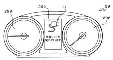
図4は、ディスプレイ292を用いた報知の一例の説明図である。
ディスプレイ292は、例えば運転席に対向して設けられたインストゥルメントパネル29に設けられている。図4の例では、ディスプレイ292に差込プラグのアイコンおよび「充電リッド(外蓋部材2206)が開いています」というメッセージからなる表示Cを行うことにより外蓋部材2206が開状態である旨を報知している。
なお、インストゥルメントパネル29には、ディスプレイ292の他、電動車両20の走行速度を表示するスピードメータ298や駆動用バッテリの電力の入出力状況を表示するパワーメータ299が設けられている。
また、ディスプレイ292に代えて、外蓋部材2206が開状態である旨を示す警告灯を設けておき、この警告灯を点灯させることによって報知を行ってもよい。
FIG. 4 is an explanatory diagram of an example of the notification using the
The
In addition to the
Further, instead of the
また、上記のような視覚を通じた報知の他、例えば電動車両20の車内に設けられたスピーカ294から外蓋部材2206が開状態である旨を音声出力することにより聴覚を通じた報知を行うようにしてもよい。さらに、例えば電動車両20のステアリングホイールや運転席のシートなどを振動させることにより外蓋部材2206が開状態である旨を報知してもよい。
In addition to the visual notification as described above, for example, a
ここで、報知部110は、外蓋部材2206が開状態である場合に外部充電器30が接続されている際は上記の報知を行わない。すなわち、報知部110は、接続検知部104により車両側コネクタ26に外部充電器30が接続されている検知された場合には、外蓋部材2206が開状態であっても報知を行わない。
車両側コネクタ26に外部充電器30が接続されている状態では、車両側コネクタ26の車両側結合面2602は露出しておらず、車両側コネクタ26にいたずらされる可能性は低い。また、車両側コネクタ26に外部充電器30が接続されている状態では電動車両20は走行できないため、外蓋部材2206の衝突による外蓋部材2206または周囲物体の破損は生じない。このような状態で外蓋部材2206が開状態である旨を報知しても、運転者は報知を無視すると予想される。よって、報知部110は、外蓋部材2206が開状態である場合に外部充電器30が接続されている際は、ユーザにとって不要な可能性の高い報知を停止して煩わしさを低減するとともに、後述するようにより適切な状況下で報知を行うことにより報知の実効性を高めている。
なお、充電が終了し、車両側コネクタ26と外部充電器30との接続が解除された場合には外蓋部材2206が開状態である旨が報知されるので、走行を開始する前に外蓋部材2206を閉めることを促すことができる。
Here, the
When the
It should be noted that when charging is completed and the connection between the vehicle-
また、例えば外蓋部材2206が変形して閉状態として認識される位置に移動できない場合や、凍結などによって外蓋部材2206の開閉機構が一時的に機能しない場合など、ユーザが外蓋部材2206が開状態であることを認識しながら走行を行わざるを得ない場合などがある。この場合に外蓋部材2206が開状態である旨を常時報知すると、ユーザに煩わしさを感じさせる可能性がある。
よって、報知部110は、電動車両20の走行状態に応じて報知の態様を変化させる。
以下、電動車両20の走行状態に応じた報知態様の変化パターンを複数示すが、これらのパターン1〜4のいずれの処理を行うかは、例えばユーザからの設定によって決定する。また、以下のパターン1〜4を適用せず、外蓋部材2206が開状態であり、かつ車両側コネクタ26と外部充電器30との接続が解除されている場合には常時外蓋部材2206が開状態である旨を報知するようにしてもよいことは無論である。
In addition, for example, when the
Therefore, the
Hereinafter, a plurality of change patterns of the notification mode according to the traveling state of the
<パターン1>車両の走行速度が所定速度以上となった際は報知を停止する。
パターン1では、報知部110は、外蓋部材2206が開状態であり、かつ車両側コネクタ26と外部充電器30とが接続されていない場合に報知を行うが、電動車両20が走行を開始した場合には走行速度が所定速度未満のうちは報知を継続し、走行速度が所定速度以上になると報知を停止する。
パターン1では、走行開始前から走行開始直後(所定速度未満)にかけて報知を行ってもユーザが外蓋部材2206を閉めない場合には、ユーザの意思により開状態を継続しているものと判断して報知を停止する。これにより、ユーザにとって不要な可能性がある報知を停止して煩わしさを低減することができる。また、例えば走行開始前後に周囲の状況確認に追われてユーザが報知に気づかない場合に、一旦報知を停止した上で例えば信号待ちなどで低速になった際に改めて報知を行うことにより、ユーザが報知に気づきやすくすることができる。
なお、所定速度を極低速(例えば時速1km)などに設定して実質的に車両の走行開始時に報知を停止するようにしてもよい。
<Pattern 1> When the traveling speed of the vehicle exceeds a predetermined speed, the notification is stopped.
In Pattern 1, the
In pattern 1, if the user does not close the
Note that the predetermined speed may be set to an extremely low speed (for example, 1 km/hour) or the like, and the notification may be substantially stopped when the vehicle starts traveling.
図5は、パターン1の処理を示すフローチャートである。
車両ECU10は、開閉検知部102により外蓋部材2206の開閉状態を検知する。外蓋部材2206が開状態の場合(ステップS500:Yes)、接続検知部104により車両側コネクタ26への外部充電器30の接続状態を検知する。車両側コネクタ26に外部充電器30が接続されている場合(ステップS502:Yes)、またはステップS500で外蓋部材2206が閉状態の場合には(ステップS500:No)、報知は行わず、ステップS500に戻り、以降の処理をくり返す。
一方、ステップS502で車両側コネクタ26に外部充電器30が接続されていない場合には(ステップS502:No)、報知部110が外蓋部材2206の開状態を報知する(ステップS504)。
その後、電動車両20が走行を開始し、走行速度が所定速度以上になるまでは(ステップS506:Noのループ)、ステップS504に戻り、報知部110による報知を継続する。そして、走行速度が所定速度以上になると(ステップS506:Yes)、報知部110は報知を停止する(ステップS508)。
FIG. 5 is a flowchart showing the processing of pattern 1.
The
On the other hand, when the
Then, until the
<パターン2>車両の走行速度が所定速度以上となった際は報知方法を他の方法に変更する。
パターン2では、報知部110は、例えば表示と音声など、複数の報知方法で報知を可能であるものとする。すなわち、報知部110は、外蓋部材2206が開状態であり、かつ車両側コネクタ26と外部充電器30とが接続されていない場合は、まず第1の方法(例えばディスプレイ292への表示)で報知を開始する。その後、電動車両20が走行を開始した場合には走行速度が所定速度未満のうちは第1の方法での報知を継続し、走行速度が所定速度以上になると第2の方法(例えば音声メッセージの出力)での報知に切り替える。このとき、第2の方法での報知とともに第1の方法での報知を継続してもよい。また、走行速度が所定速度以上になったタイミングで第2の方法での報知を所定時間行い、その後はパターン1のように報知を停止してもよい。
パターン2では、走行開始前から走行開始直後(所定速度未満)にかけて報知を行ってもユーザが外蓋部材2206を閉めない場合には、報知の方法がユーザの状況と適合しておらず、ユーザに報知の内容が伝達されていない可能性がある判断する。例えば逆光下やスモッグ発生時などではユーザは周囲の状況確認のため車外に多くの注意を払い、表示での報知では伝わりにくい可能性がある。また、降雨量や周囲の交通量が多い場合、カーステレオを使用している場合などは、音声による報知では伝わりにくい可能性がある。パターン2のように報知の方法を変更することによって、ユーザに報知の内容を伝達しやすくすることができる。
なお、所定速度を極低速(例えば時速1km)などに設定して実質的に車両の走行開始時に報知方法を変更するようにしてもよい。
<Pattern 2> When the traveling speed of the vehicle exceeds a predetermined speed, the notification method is changed to another method.
In pattern 2, the
In pattern 2, if the user does not close the
Note that the predetermined speed may be set to an extremely low speed (for example, 1 km/hour) and the notification method may be changed substantially when the vehicle starts traveling.
図6は、パターン2の処理を示すフローチャートである。
ステップS600およびステップS602は、図5のステップS500およびステップS502と同様であるため、説明を省略する。
外蓋部材2206が開状態であり(ステップS600:Yes)、かつ車両側コネクタ26に外部充電器30が接続されていない場合には(ステップS602:No)、報知部110は、まず第1の方法(例えば表示)で外蓋部材2206の開状態を報知する(ステップS604)。
その後、電動車両20が走行を開始し、走行速度が所定速度以上になるまでは(ステップS606:Noのループ)、ステップS604に戻り、第1の方法による報知を継続する。そして、走行速度が所定速度以上になると(ステップS606:Yes)、報知部110は第2の方法(例えば音声)で外蓋部材2206の開状態を報知する(ステップS608)。
FIG. 6 is a flowchart showing the processing of pattern 2.
Since step S600 and step S602 are the same as step S500 and step S502 in FIG. 5, description thereof will be omitted.
If the
Then, until the
<パターン3>車両が走行を開始した場合には一旦報知を停止するとともに、車両の走行速度が所定速度以上となった際は再度報知を行う。
パターン3では、報知部110は、外蓋部材2206が開状態であり、かつ車両側コネクタ26と外部充電器30とが接続されていない場合に報知を行うが、電動車両20が走行を開始した場合には一旦報知を停止し、走行速度が所定速度以上になると報知を再開する。
パターン3では、走行開始前から走行開始にかけて報知を行ってもユーザが外蓋部材2206を閉めない場合には、ユーザの意思により開状態を継続しているものと判断して、走行開始時に一旦報知を停止する。これにより、ユーザにとって不要な可能性がある報知を停止して煩わしさを低減することができる。そして、万一ユーザが走行開始前の報知に気づいていない場合を考慮して走行速度がより高速になる前に再度報知を行うことにより、ユーザの意思を再確認する。例えば走行開始前に周囲の状況確認に追われてユーザが報知に気づかなかった場合に、一旦報知を停止した上で、走行状況が安定したと考えられる時点で改めて報知を行うことにより、ユーザが報知に気づきやすくすることができる。
なお、一旦報知を停止するタイミングを、走行開始時ではなく、走行速度が第1の所定速度以上になった場合とし、報知を再開するタイミングを走行速度が第2の所定速度(>第1の所定速度)以上になった場合としてもよい。
<Pattern 3> When the vehicle starts traveling, the notification is temporarily stopped, and when the traveling speed of the vehicle becomes a predetermined speed or more, the notification is performed again.
In pattern 3, the
In pattern 3, if the user does not close the
Note that the notification is temporarily stopped at a time when the traveling speed is equal to or higher than the first predetermined speed rather than at the start of traveling, and the notification is restarted when the traveling speed is the second predetermined speed (>the first predetermined speed). The speed may be equal to or higher than a predetermined speed).
図7は、パターン3の処理を示すフローチャートである。
ステップS700およびステップS702は、図5のステップS500およびステップS502と同様であるため、説明を省略する。
外蓋部材2206が開状態であり(ステップS700:Yes)、かつ車両側コネクタ26に外部充電器30が接続されていない場合(ステップS702:No)、報知部110は、外蓋部材2206の開状態を報知する(ステップS704)。
報知部110は、電動車両20が走行を開始するまでは(ステップS706:Noのループ)、ステップS704に戻り、報知を継続する。そして、電動車両20が走行を開始すると(ステップS706:Yes)、報知を停止する(ステップS708)。
その後、走行速度が所定速度以上になるまでは(ステップS710:Noのループ)、報知を停止した状態を継続し、走行速度が所定速度以上になると(ステップS710:Yes)、再度外蓋部材2206の開状態を報知する(ステップS712)。
FIG. 7 is a flowchart showing the processing of pattern 3.
Since step S700 and step S702 are the same as step S500 and step S502 in FIG. 5, description thereof will be omitted.
When the
The
After that, until the traveling speed becomes equal to or higher than the predetermined speed (step S710: loop of No), the state in which the notification is stopped is continued, and when the traveling speed becomes equal to or higher than the predetermined speed (step S710: Yes), the
<パターン4>シフトレバー296が車両を走行可能なシフトレンジに操作された場合には報知を停止する。
パターン4では、報知部110は、外蓋部材2206が開状態であり、かつ車両側コネクタ26と外部充電器30とが接続されておらず、かつシフトレンジが車両を走行不可なシフトレンジ、例えばPレンジやNレンジなどに設定されている場合に報知を行う。なお、一般に車両側コネクタ26と外部充電器30が接続されている間、シフトレンジは車両を走行不可なシフトレンジ、例えばPレンジやNレンジなどに設定されていると予想される。このため、車両側コネクタ26と外部充電器30との接続が解除された直後は報知が行われると予測される。その後、シフトレバー296(シフト設定部)が車両を走行可能なシフトレンジ、例えばDレンジやBレンジ、Rレンジなどに操作された場合には、報知部110は報知を停止する。
パターン4では、車両の停車中(シフトレンジがPレンジやNレンジにある時)に報知を行ってもユーザが外蓋部材2206を閉めない場合には、ユーザの意思により開状態を継続しているものと判断して、ユーザが走行の意思を示した際(シフトレンジがDレンジやBレンジ、Rレンジなどに操作された場合)に報知を停止する。これにより、ユーザにとって不要な可能性がある報知を停止して煩わしさを低減することができる。
なお、パターン4でもパターン3と同様に、報知を停止後、走行速度が所定速度以上になった際に報知を再開してもよい。
<Pattern 4> When the
In pattern 4, the
In pattern 4, if the user does not close the
In pattern 4, as in pattern 3, the notification may be restarted when the traveling speed becomes equal to or higher than the predetermined speed after the notification is stopped.
図8は、パターン4の処理を示すフローチャートである。
ステップS800およびステップS802は、図5のステップS500およびステップS502と同様であるため、説明を省略する。
外蓋部材2206が開状態であり(ステップS800:Yes)、かつ車両側コネクタ26に外部充電器30が接続されていない場合(ステップS802:No)、報知部110は、シフトレバー296が車両を走行不可なシフトレンジ(PレンジやNレンジなど)に操作されているか否かを判断する(ステップS804:Noのループ)。
車両を走行不可なシフトレンジ(PレンジやNレンジなど)に操作されている場合(ステップS804:Yes)、報知部110は、外蓋部材2206の開状態を報知する(ステップS806)。
シフトレバー296が車両を走行不可なシフトレンジ(PレンジやNレンジなど)に操作されている間は(ステップS808:Noのループ)、ステップS806に戻り、報知を継続する。そして、シフトレバー296が車両を走行可能なシフトレンジ(DレンジやBレンジ、Rレンジなど)に操作されると(ステップS808:Yes)、報知部110は報知を停止する(ステップS810)。
FIG. 8 is a flowchart showing the processing of pattern 4.
Since step S800 and step S802 are the same as step S500 and step S502 in FIG. 5, description thereof will be omitted.
When the
When the vehicle is operated in the shift range in which the vehicle cannot travel (P range, N range, etc.) (step S804: Yes), the
While the
以上説明したように、実施の形態にかかる電動車両20によれば、車両側コネクタ26を覆う外蓋部材2206が開状態である際に車両側コネクタ26に外部充電器30が接続されている場合には、外蓋部材2206が開状態である旨の報知を停止する。これにより、ユーザにとって不要な可能性の高い報知を停止して煩わしさを低減するとともに、より適切な状況下で報知を行うことにより報知の実効性を高める上で有利となる。
また、電動車両20において、車両の走行速度が所定速度以上になると報知を停止するようにすれば(パターン1)、ユーザにとって不要な可能性がある報知を停止して煩わしさを低減する上で有利となる。また、一旦報知を停止した上で例えば信号待ちなどで低速になった際に改めて報知を行うことにより、ユーザに報知を気づかせやすくする上で有利となる。
また、電動車両20において、車両の走行速度が所定速度未満の場合と所定速度以上の場合とで報知方法を変更するようにすれば(パターン2)、ユーザに報知の内容をより確実にユーザに伝達する上で有利となる。
また、電動車両20において、車両が走行を開始した場合には一旦報知を停止するとともに、車両の走行速度が所定速度以上となった際は再度報知を行うようにすれば(パターン3)、これにより、ユーザにとって不要な可能性がある報知を停止して煩わしさを低減するとともに、仮にユーザが走行開始前の報知に気づいていない場合を考慮して再報知を行うことにより蓋部材の予期せぬ破損等を防止する上で有利となる。
また、電動車両20において、シフトレバー296が車両を走行可能なシフトレンジに操作された場合には報知を停止するようにすれば(パターン4)、ユーザにとって不要な可能性がある報知を停止して煩わしさを低減することができる。
As described above, according to the
Further, in the
Further, in the
In addition, in the
Further, in the
なお、本実施の形態では、本発明にかかる車両が駆動用エネルギーとして電力を用いる電動車両であるものとして説明したが、これに限らず、本発明は駆動用エネルギーとして燃料(ガソリンやメタノール、水素など)を用いる車両にも適用可能である。
また、本実施の形態では外蓋部材2206が請求項における蓋部材であるものとしたが、これに限らず、車両側結合面2602を覆う内蓋部材2604に対しても適用可能である。
In the present embodiment, the vehicle according to the present invention has been described as being an electric vehicle that uses electric power as driving energy, but the present invention is not limited to this, and the present invention uses fuel (gasoline, methanol, hydrogen) as driving energy. Etc.) is also applicable to vehicles using.
Further, although the
10 車両ECU
102 開閉検知部
104 接続検知部
106 速度検知部
108 シフト検知部
110 報知部
20 電動車両
22 充電口
2202 開口部
2204 凹部
2206 外蓋部材
26 車両側コネクタ
2602 車両側結合面
2604 内蓋部材
28 照明装置
292 ディスプレイ
294 スピーカ
296 シフトレバー
30 外部充電器
10 Vehicle ECU
102 Open/
Claims (3)
前記蓋部材が開状態である場合に報知する報知部と、
前記インターフェースへの駆動用エネルギー供給装置の接続状態を検知する接続検知部と、
前記車両の走行速度を検知する速度検知部と、を備え、
前記報知部は、前記蓋部材が開状態である際に前記インターフェースに前記駆動用エネルギー供給装置が接続されている場合には報知を行わず、かつ前記蓋部材が開状態である場合に前記車両の走行速度が所定速度以上となった際は報知を停止する、
ことを特徴とする車両。 A vehicle for notifying an open/closed state of a lid member that covers an interface for supplying driving energy,
A notifying unit for notifying when the lid member is in the open state,
A connection detection unit for detecting a connection state of the driving energy supply device to the interface,
A speed detection unit that detects the traveling speed of the vehicle,
The notification unit does not notify when the drive energy supply device is connected to the interface when the lid member is in the open state, and the vehicle when the lid member is in the open state. When the traveling speed of is above a predetermined speed, the notification is stopped,
A vehicle characterized in that.
前記蓋部材が開状態である場合に報知する報知部と、 A notifying unit for notifying when the lid member is in the open state,
前記インターフェースへの駆動用エネルギー供給装置の接続状態を検知する接続検知部と、 A connection detection unit for detecting the connection state of the driving energy supply device to the interface,
前記車両の走行速度を検知する速度検知部と、を備え、 A speed detection unit that detects the traveling speed of the vehicle,
前記報知部は、前記蓋部材が開状態である際に前記インターフェースに前記駆動用エネルギー供給装置が接続されている場合には報知を行わず、かつ前記蓋部材が開状態である場合に前記車両が走行を開始した際には報知を停止するとともに、前記車両の走行速度が所定速度以上となった際は再度報知を行う、 The notification unit does not notify when the drive energy supply device is connected to the interface when the lid member is in the open state, and the vehicle when the lid member is in the open state. Stops the notification when the vehicle starts traveling, and notifies again when the traveling speed of the vehicle becomes a predetermined speed or more,
ことを特徴とする車両。 A vehicle characterized in that.
前記蓋部材が開状態である場合に報知する報知部と、 A notifying unit for notifying when the lid member is in the open state,
前記インターフェースへの駆動用エネルギー供給装置の接続状態を検知する接続検知部と、 A connection detection unit for detecting a connection state of the driving energy supply device to the interface,
前記車両のシフト設定部への操作状態を検知するシフト検知部と、を備え、A shift detection unit that detects an operation state of the shift setting unit of the vehicle,
前記報知部は、前記蓋部材が開状態である際に前記インターフェースに前記駆動用エネルギー供給装置が接続されている場合には報知を行わず、かつ前記シフト設定部が前記車両を走行可能なシフトレンジに操作されている場合には報知を停止する、 The notification unit does not notify when the drive energy supply device is connected to the interface when the lid member is in the open state, and the shift setting unit allows the vehicle to run the shift. When the range is operated, the notification is stopped,
ことを特徴とする車両。 A vehicle characterized in that.
Priority Applications (4)
| Application Number | Priority Date | Filing Date | Title |
|---|---|---|---|
| JP2016224016A JP6708100B2 (en) | 2016-11-17 | 2016-11-17 | vehicle |
| US15/814,827 US10655590B2 (en) | 2016-11-17 | 2017-11-16 | Vehicle |
| EP17202063.8A EP3323660B1 (en) | 2016-11-17 | 2017-11-16 | Electric vehicle charged by external power supply |
| CN201711143249.8A CN108068622B (en) | 2016-11-17 | 2017-11-17 | Automobile with a detachable front cover |
Applications Claiming Priority (1)
| Application Number | Priority Date | Filing Date | Title |
|---|---|---|---|
| JP2016224016A JP6708100B2 (en) | 2016-11-17 | 2016-11-17 | vehicle |
Publications (2)
| Publication Number | Publication Date |
|---|---|
| JP2018079819A JP2018079819A (en) | 2018-05-24 |
| JP6708100B2 true JP6708100B2 (en) | 2020-06-10 |
Family
ID=60382115
Family Applications (1)
| Application Number | Title | Priority Date | Filing Date |
|---|---|---|---|
| JP2016224016A Active JP6708100B2 (en) | 2016-11-17 | 2016-11-17 | vehicle |
Country Status (4)
| Country | Link |
|---|---|
| US (1) | US10655590B2 (en) |
| EP (1) | EP3323660B1 (en) |
| JP (1) | JP6708100B2 (en) |
| CN (1) | CN108068622B (en) |
Families Citing this family (5)
| Publication number | Priority date | Publication date | Assignee | Title |
|---|---|---|---|---|
| JP7225605B2 (en) * | 2018-08-22 | 2023-02-21 | スズキ株式会社 | Vehicle charging lid opener |
| JP6787959B2 (en) * | 2018-09-20 | 2020-11-18 | 株式会社Subaru | Power connector disconnection device |
| CN112776898B (en) * | 2021-03-11 | 2022-06-21 | 北京车和家信息技术有限公司 | Control method and control device for vehicle door cover, vehicle-mounted system and vehicle |
| DE102021125153A1 (en) * | 2021-09-28 | 2023-03-30 | Audi Aktiengesellschaft | Charging socket arrangement for a vehicle |
| US11735932B2 (en) * | 2021-10-30 | 2023-08-22 | Beta Air, Llc | System and methods for an immediate shutdown of an electric vehicle charger |
Family Cites Families (13)
| Publication number | Priority date | Publication date | Assignee | Title |
|---|---|---|---|---|
| JP3992907B2 (en) | 2000-06-16 | 2007-10-17 | 日産ディーゼル工業株式会社 | Car alarm device |
| ATE377846T1 (en) * | 2005-10-19 | 2007-11-15 | Fiat Ricerche | DEVICE FOR STORING ELECTRICAL ENERGY FOR SUPPLYING HIGH PRIORITY ELECTRICAL LOADS, PARTICULARLY FOR MOTOR VEHICLES |
| US20100066890A1 (en) * | 2005-12-06 | 2010-03-18 | Panasonic Corporation | Digital camera |
| JP4367559B2 (en) * | 2007-08-10 | 2009-11-18 | トヨタ自動車株式会社 | vehicle |
| JP4400660B2 (en) | 2007-09-04 | 2010-01-20 | トヨタ自動車株式会社 | Electric vehicle |
| DE102010011767A1 (en) * | 2010-03-17 | 2011-09-22 | Brose Fahrzeugteile Gmbh & Co. Kg, Hallstadt | Method for sensory detection of an operator event |
| US8346423B2 (en) * | 2010-06-07 | 2013-01-01 | Ford Global Technologies, Llc | Plug-in electric vehicle interlock |
| EP2698271B1 (en) | 2011-04-12 | 2018-09-05 | Toyota Jidosha Kabushiki Kaisha | Vehicle and method for controlling vehicle |
| JP5622798B2 (en) | 2012-07-03 | 2014-11-12 | 本田技研工業株式会社 | vehicle |
| JP2014066076A (en) * | 2012-09-26 | 2014-04-17 | Daihatsu Motor Co Ltd | Vehicle door control device |
| JP6089538B2 (en) | 2012-09-26 | 2017-03-08 | 株式会社バッファロー | Electronic device, system, and program |
| JP6299659B2 (en) * | 2014-11-13 | 2018-03-28 | トヨタ自動車株式会社 | Vehicle equipped with fuel cell and control method thereof |
| CN105857083A (en) * | 2016-06-15 | 2016-08-17 | 中国重汽集团济南动力有限公司 | Opening monitoring system of box cover of high-voltage distribution box of pure electric vehicle |
-
2016
- 2016-11-17 JP JP2016224016A patent/JP6708100B2/en active Active
-
2017
- 2017-11-16 US US15/814,827 patent/US10655590B2/en active Active
- 2017-11-16 EP EP17202063.8A patent/EP3323660B1/en active Active
- 2017-11-17 CN CN201711143249.8A patent/CN108068622B/en active Active
Also Published As
| Publication number | Publication date |
|---|---|
| US10655590B2 (en) | 2020-05-19 |
| US20180135585A1 (en) | 2018-05-17 |
| EP3323660A1 (en) | 2018-05-23 |
| CN108068622B (en) | 2020-11-06 |
| EP3323660B1 (en) | 2020-09-23 |
| JP2018079819A (en) | 2018-05-24 |
| CN108068622A (en) | 2018-05-25 |
Similar Documents
| Publication | Publication Date | Title |
|---|---|---|
| JP6708100B2 (en) | vehicle | |
| US9108517B2 (en) | Plug-in electric vehicle interlock | |
| JP4437496B2 (en) | In-vehicle display controller | |
| JP4659873B2 (en) | VEHICLE, ITS CONTROL METHOD AND DRIVE DEVICE | |
| CN101795894B (en) | On-vehicle display device | |
| CN109591824B (en) | Safe driving assisting method | |
| JP5657410B2 (en) | Vehicle travel control device | |
| JP2012034440A (en) | Shift device | |
| JP3227175U (en) | Vehicle display device | |
| CN106799990A (en) | Vehicle and its control method | |
| JP2008029165A (en) | Vehicle, control method thereof and power system | |
| KR101009477B1 (en) | Vehicle Battery Saver System | |
| CN101723016B (en) | Anti-theft device for motorcycle | |
| CA2846976C (en) | Engine non-stop warning apparatus | |
| JP2005119602A (en) | Anti-theft apparatus for vehicle | |
| CN112339664B (en) | Control system and control method for automobile electronic exterior rearview mirror | |
| KR20160023268A (en) | Vehicle having the same and method for controlling the same | |
| CN107953826A (en) | With the navigator for turning to warning function | |
| US20230174081A1 (en) | Vehicle control device | |
| CN214564964U (en) | Pedestrian PD detection system for hydrogen energy automobile | |
| US20220024341A1 (en) | Warning device for a charging process for electric vehicles | |
| JP2013068216A (en) | On-board speed reducing device | |
| JP2010137689A (en) | Falling prevention device of trailer | |
| JP2017022966A (en) | Electric-vehicular control apparatus | |
| JP2007245949A (en) | Power supply monitoring device, and electrical unit |
Legal Events
| Date | Code | Title | Description |
|---|---|---|---|
| A621 | Written request for application examination |
Free format text: JAPANESE INTERMEDIATE CODE: A621 Effective date: 20190322 |
|
| A977 | Report on retrieval |
Free format text: JAPANESE INTERMEDIATE CODE: A971007 Effective date: 20200115 |
|
| A131 | Notification of reasons for refusal |
Free format text: JAPANESE INTERMEDIATE CODE: A131 Effective date: 20200121 |
|
| A521 | Request for written amendment filed |
Free format text: JAPANESE INTERMEDIATE CODE: A523 Effective date: 20200313 |
|
| TRDD | Decision of grant or rejection written | ||
| A01 | Written decision to grant a patent or to grant a registration (utility model) |
Free format text: JAPANESE INTERMEDIATE CODE: A01 Effective date: 20200421 |
|
| A61 | First payment of annual fees (during grant procedure) |
Free format text: JAPANESE INTERMEDIATE CODE: A61 Effective date: 20200504 |
|
| R151 | Written notification of patent or utility model registration |
Ref document number: 6708100 Country of ref document: JP Free format text: JAPANESE INTERMEDIATE CODE: R151 |