JP7187828B2 - vehicle - Google Patents
vehicle Download PDFInfo
- Publication number
- JP7187828B2 JP7187828B2 JP2018109549A JP2018109549A JP7187828B2 JP 7187828 B2 JP7187828 B2 JP 7187828B2 JP 2018109549 A JP2018109549 A JP 2018109549A JP 2018109549 A JP2018109549 A JP 2018109549A JP 7187828 B2 JP7187828 B2 JP 7187828B2
- Authority
- JP
- Japan
- Prior art keywords
- charging
- power supply
- state
- battery
- external device
- Prior art date
- Legal status (The legal status is an assumption and is not a legal conclusion. Google has not performed a legal analysis and makes no representation as to the accuracy of the status listed.)
- Active
Links
Images


Classifications
-
- Y—GENERAL TAGGING OF NEW TECHNOLOGICAL DEVELOPMENTS; GENERAL TAGGING OF CROSS-SECTIONAL TECHNOLOGIES SPANNING OVER SEVERAL SECTIONS OF THE IPC; TECHNICAL SUBJECTS COVERED BY FORMER USPC CROSS-REFERENCE ART COLLECTIONS [XRACs] AND DIGESTS
- Y02—TECHNOLOGIES OR APPLICATIONS FOR MITIGATION OR ADAPTATION AGAINST CLIMATE CHANGE
- Y02T—CLIMATE CHANGE MITIGATION TECHNOLOGIES RELATED TO TRANSPORTATION
- Y02T10/00—Road transport of goods or passengers
- Y02T10/60—Other road transportation technologies with climate change mitigation effect
- Y02T10/70—Energy storage systems for electromobility, e.g. batteries
-
- Y—GENERAL TAGGING OF NEW TECHNOLOGICAL DEVELOPMENTS; GENERAL TAGGING OF CROSS-SECTIONAL TECHNOLOGIES SPANNING OVER SEVERAL SECTIONS OF THE IPC; TECHNICAL SUBJECTS COVERED BY FORMER USPC CROSS-REFERENCE ART COLLECTIONS [XRACs] AND DIGESTS
- Y02—TECHNOLOGIES OR APPLICATIONS FOR MITIGATION OR ADAPTATION AGAINST CLIMATE CHANGE
- Y02T—CLIMATE CHANGE MITIGATION TECHNOLOGIES RELATED TO TRANSPORTATION
- Y02T10/00—Road transport of goods or passengers
- Y02T10/60—Other road transportation technologies with climate change mitigation effect
- Y02T10/7072—Electromobility specific charging systems or methods for batteries, ultracapacitors, supercapacitors or double-layer capacitors
-
- Y—GENERAL TAGGING OF NEW TECHNOLOGICAL DEVELOPMENTS; GENERAL TAGGING OF CROSS-SECTIONAL TECHNOLOGIES SPANNING OVER SEVERAL SECTIONS OF THE IPC; TECHNICAL SUBJECTS COVERED BY FORMER USPC CROSS-REFERENCE ART COLLECTIONS [XRACs] AND DIGESTS
- Y02—TECHNOLOGIES OR APPLICATIONS FOR MITIGATION OR ADAPTATION AGAINST CLIMATE CHANGE
- Y02T—CLIMATE CHANGE MITIGATION TECHNOLOGIES RELATED TO TRANSPORTATION
- Y02T90/00—Enabling technologies or technologies with a potential or indirect contribution to GHG emissions mitigation
- Y02T90/10—Technologies relating to charging of electric vehicles
- Y02T90/14—Plug-in electric vehicles
Landscapes
- Charge And Discharge Circuits For Batteries Or The Like (AREA)
- Electric Propulsion And Braking For Vehicles (AREA)
Description
本発明は、充給電装置を備えた車両に関する。 TECHNICAL FIELD The present invention relates to a vehicle equipped with a charging/power supply device.
従来、電気自動車やハイブリッド自動車等の電動車両において、駆動用バッテリの直流電力(DC)を交流電力(AC)に変換して、車内に設置したコンセントから利用する技術が知られている。
最近では、車内に設けられたコンセントのみでは電気機器の使用が困難であるため、車体外部に面する位置にコンセントを配置して使用する技術も知られており、その際にコンセントを接続したまま車両が発進することを防止する技術が知られている(例えば「特許文献1」参照)。
Conventionally, in an electric vehicle such as an electric vehicle or a hybrid vehicle, a technology is known in which direct current power (DC) of a driving battery is converted into alternating current power (AC) and used from an outlet installed in the vehicle.
Recently, it is difficult to use electrical equipment with only the outlet provided inside the vehicle, so there is also a known technique to use an outlet facing the outside of the vehicle. A technique for preventing a vehicle from starting is known (see, for example, "Patent Document 1").
上述した技術では、充電口にアダプタを接続して給電を行う際には、車両走行禁止となるように駆動モータのトルクをゼロにさせる制御を行っている。
通常車両は、充電中や給電中は外部電源や外部機器とケーブル等によって接続されているため、車両のシステムを起動した状態(レディオン状態)で走行禁止にするか、車両のシステムを停止した状態(レディオフ状態)とする。充電や給電をレディオン状態で行う場合、バッテリの電力収支を常時監視できハイブリッド車の場合では状況に応じてエンジンを発電機として使用することができるが、システムが起動しているため消費電力が発生し、車両を発進させた場合には外部電源や外部機器、ケーブル等を破損させる虞もある。また、充電や給電をレディオフ状態で行う場合、システムが停止しているため消費電力が発生せず、車両を発進させようとした場合でもレディオンの動作が入るため外部電源や外部機器、ケーブル等の接続に気付き易く破損を抑制できるが、給電の場合にはバッテリ容量が少なくなり、システムが起動できなくなる虞もある。
本発明は上述の問題点を解決し、状態に応じて適切に充電及び給電を行うことが可能な車両の提供を目的とする。
In the above-described technology, when the adapter is connected to the charging port and power is supplied, control is performed to reduce the torque of the drive motor to zero so that the vehicle is prohibited from running.
Normally, a vehicle is connected to an external power source or external device by a cable, etc. while it is being charged or supplied with electricity. (ready-off state). When charging or supplying power in the ready-on state, the power balance of the battery can be constantly monitored.In the case of a hybrid vehicle, the engine can be used as a generator depending on the situation, but power consumption occurs because the system is running. However, when the vehicle is started, the external power supply, external equipment, cables, etc. may be damaged. In addition, when charging or supplying power in the ready-off state, the system is stopped, so power consumption does not occur, and even if you try to start the vehicle, the ready-on operation is activated, so external power sources, external devices, cables, etc. Although it is easy to notice the connection and damage can be suppressed, in the case of power supply, the battery capacity is reduced, and there is a possibility that the system cannot be started.
SUMMARY OF THE INVENTION An object of the present invention is to solve the above-described problems and to provide a vehicle capable of appropriately charging and supplying power depending on the state.
請求項1記載の発明は、モータとバッテリとを有し、前記モータと前記バッテリとを制御する駆動システムと、前記駆動システムの状態を起動状態または停止状態に切り替える切替手段と、外部機器を接続され、前記バッテリの充給電を行う充給電部とを備えた車両において、前記充給電部は、前記外部機器から前記バッテリに充電する充電回路と、前記充電回路に設けられ、前記外部機器と接続可能な充電部と、前記バッテリから前記外部機器に電力を取り出す給電回路と、前記給電回路に設けられ、前記外部機器と接続可能な給電部と、を有し、前記駆動システムが前記起動状態のとき前記給電回路を優先させ、前記駆動システムが前記停止状態のとき前記充電回路を優先させる制御手段を備え、前記起動状態のとき前記充電部と重なる位置にスライド移動して前記給電部を露出すると共に前記充電部を遮蔽し、前記停止状態のとき前記給電部と重なる位置にスライド移動して前記給電部を遮蔽すると共に前記充電部を露出するカバーを有することを特徴とする。 The invention according to claim 1 has a motor and a battery, and connects a drive system for controlling the motor and the battery, switching means for switching the state of the drive system between an active state and a stopped state, and an external device. and a charging/feeding section that charges and feeds the battery, wherein the charging/feeding section includes: a charging circuit that charges the battery from the external device; and a charging circuit that is provided in the charging circuit and is connected to the external device. a power supply circuit for extracting power from the battery to the external device ; and a power supply unit provided in the power supply circuit and connectable to the external device, wherein the drive system is in the activated state. a control means for giving priority to the power supply circuit when the drive system is in the stopped state, and giving priority to the charging circuit when the drive system is in the stopped state ; and covering the charging section, and slidingly moved to a position overlapping the power feeding section in the stopped state to cover the power feeding section and expose the charging section .
請求項2記載の発明は、モータとバッテリとを有し、前記モータと前記バッテリとを制御する駆動システムと、前記駆動システムの状態を起動状態または停止状態に切り替える切替手段と、外部機器を接続され、前記バッテリの充給電を行う充給電部とを備えた車両において、前記充給電部は、前記外部機器から前記バッテリに充電する充電回路と、前記充電回路に設けられ、前記外部機器と接続可能な充電部と、前記バッテリから前記外部機器に電力を取り出す給電回路と、前記給電回路に設けられ、前記外部機器と接続可能な給電部と、を有し、前記駆動システムが前記起動状態のとき前記充電回路を遮断すると共に前記給電回路を優先させ、前記駆動システムが前記停止状態のとき前記給電回路を遮断すると共に前記充電回路を優先させる制御手段を備え、前記起動状態のとき前記充電部を遮蔽すると共に前記給電部を露出し、前記停止状態のとき前記充電部を露出すると共に前記給電部を遮蔽する移動手段と、前記給電部を支持し、前記移動手段によって移動されるコンセント支持部材とを有し、前記移動手段は前記起動状態のとき前記コンセント支持部材を前記充電部と重なる位置に移動させることを特徴とする。 According to a second aspect of the present invention, there is provided a motor and a battery, wherein a drive system for controlling the motor and the battery, switching means for switching the state of the drive system between a start state and a stop state, and an external device are connected. and a charging/feeding section that charges and feeds the battery, wherein the charging/feeding section includes: a charging circuit that charges the battery from the external device; and a charging circuit that is provided in the charging circuit and is connected to the external device. a power supply circuit for extracting power from the battery to the external device; and a power supply unit provided in the power supply circuit and connectable to the external device, wherein the drive system is in the activated state. control means for interrupting the charging circuit and prioritizing the power supply circuit when the drive system is in the stopped state, and interrupting the power supply circuit and giving priority to the charging circuit when the drive system is in the stopped state; and exposing the power supply unit, and exposing the charging unit and shielding the power supply unit in the stopped state; and an outlet support member that supports the power supply unit and is moved by the moving unit. , wherein the moving means moves the outlet support member to a position overlapping with the charging portion in the activated state .
本発明によれば、制御手段が駆動システムの起動状態時に給電動作を優先させるので制御手段が残充電量情報を得ることができ、駆動システムの停止状態時に充電動作を優先させるので充電量不足の発生を防止することができる。 According to the present invention, since the control means gives priority to the power supply operation when the drive system is in the activated state, the control means can obtain the remaining charge amount information. occurrence can be prevented.
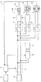
図1は、本発明の第1の実施形態を適用可能な車両を示している。同図において電気自動車(EV)である車両1は、車体2の後部に充給電装置としての充給電部3を有している。充給電部3は、図2に示すように、給電回路23(図3参照)の一部である交流給電用のコンセント4、充電回路24(図3参照)の一部である普通充電用の普通充電インレット5、充電回路25(図3参照)の一部である急速充電インレット6、開閉自在な充電リッド7、コンセント4及び各インレット5,6を収容し充電リッド7を開閉自在に支持する車体2に一体的に形成された収容部17、後述するコンタクタ11,16,18,19及び制御手段としてのECU9等を備えている。
FIG. 1 shows a vehicle to which a first embodiment of the invention can be applied. In the figure, a vehicle 1, which is an electric vehicle (EV), has a charging/
給電部として機能するコンセント4は収容部17に対して移動可能に構成されており、図示しない通常の家庭用100Vプラグが接続されることにより、後述する駆動用バッテリ10から外部家電(外部機器)に対して給電が行われる。コンセント4はコンセント支持部材21によって支持されており、コンセント支持部材21は図示しないレール部材によって収容部17に対して上下動自在に支持されている。コンセント支持部材21には、図示しないラックアンドピニオン機構を介して移動手段としてのモータ22が接続されており、モータ22の作動によりコンセント4は、図2に実線で示す給電可能位置と二点鎖線で示す充電可能位置とを選択的に占める。
The
コンセント4が露出した状態である給電可能位置を占めたとき、コンセント支持部材21によって各インレット5,6がそれぞれ一部を覆われるため、各インレット5,6がコンセント支持部材21により遮蔽され、コネクタの接続が不可能となる。よって、給電が優先されることとなる。また、コンセント4が充電可能位置を占めたときコンセント支持部材21は車体2によって覆われる位置を占めるため、コンセント4が車体2により遮蔽され、プラグの接続が不可能となる。よって、充電が優先されることとなる。
When the
充電部として機能する普通充電インレット5は車体2に固定されており、図示しない交流の普通充電用コネクタが接続されることにより、後述する駆動用バッテリに対して外部電源(外部機器)より普通充電が行われる。
充電部として機能する急速充電インレット6は車体2に固定されており、図示しない直流の急速充電用コネクタが接続されることにより、後述する駆動用バッテリに対して外部電源より急速充電が行われる。
コンセント4及び各インレット5,6には、それぞれプラグ及びコネクタの接続が行われた場合に後述するECU9に対して信号を出力する図示しないスイッチがそれぞれ設けられている。
A
A
The
車体2の内部である車室内の図示しないインストゥルメントパネルには、運転者によって操作される切替手段としての始動スイッチ8が設けられている。始動スイッチ8は、車両1の走行が可能であると共に車内機器の使用が可能なレディオン状態と、車両1の走行が不可であると共に車内機器の使用が可能なレディオフ状態とを選択的に占める。
また車体2の内部には、制御手段としてのECU9を備えた、後述する駆動モータ12及び駆動用バッテリ10の作動を制御する駆動システム20が配設されている。ECU9は、図示しないCPU、ROM、RAM、I/Oポート等を有する周知のマイクロコンピュータによって構成されている。駆動システム20は、レディオン状態時に起動状態を、レディオフ状態時に停止状態をそれぞれ占める。
An instrument panel (not shown) in the interior of the
Further, inside the
図3は、駆動システム20の制御ブロック図を示している。同図においてECU9は、始動スイッチ8からの信号、及びコンセント4、各インレット5,6から送られる接続信号に基づいてバッテリとしての駆動用バッテリ10に接続されたコンタクタ11、車両1を駆動するモータとしての駆動モータ12に接続されたインバータ13、交流用電気機器が接続されるコンセント4に接続され直流を交流に変換するDCACインバータ14及びこれに接続されたコンタクタ18、交流充電コネクタが接続される普通充電インレット5に接続され交流を直流に変換するACDCインバータ15及びこれに接続されたコンタクタ19、直流充電コネクタが接続される急速充電インレット6に接続されたコンタクタ16の動作をそれぞれ制御する。
FIG. 3 shows a control block diagram of the
なおコンタクタ11は、始動スイッチ8がオン状態時には接続状態、始動スイッチ8がオフ状態の時には非接続状態であり、始動スイッチ8のオフ状態時に各インレット5,6の何れかにコネクタが接続されると、コネクタの接続信号を受けて接続動作が行われる。コンタクタ11の接続状態時において、ECU9は図示しない充電量検知手段からの残充電量情報を得ることができる。
図3に示す構成において、DCACインバータ14、コンタクタ18、コンセント4によって給電回路23が、ACDCインバータ15、コンタクタ19、普通充電インレット5によって充電回路24が、コンタクタ16、急速充電インレット6によって充電回路25がそれぞれ構成されている。
The
In the configuration shown in FIG. 3 , the DCAC inverter 14 , the
上述の構成に基づき、第1の実施形態における充給電部3の動作を、図4に示すフローチャートに基づいて説明する。
先ずECU9は、始動スイッチ8がオンされているか否かを判定する(ST01)。オンされていると判定した場合には、給電動作を優先させるべくECU9はモータ22を作動させて(ST02)コンセント4を給電可能位置に位置決めさせる(ST03)。なお、本実施形態ではコンセント4が予め充電可能位置を占めている場合を説明する。コンセント4が給電可能位置を占めると、車両使用者により図示しないプラグが接続されて給電動作が実施される(ST04)。
Based on the above configuration, the operation of the charging/
First, the ECU 9 determines whether or not the
ステップST01において始動スイッチ8がオンされていないとECU9が判定すると、充電動作を優先させるべく予め充電可能位置を占めているコンセント4を移動させる必要がないことから、ECU9はモータ22を作動させず(ST05)コンセント4は充電可能位置を占めた状態を維持する(ST06)。この状態では、図2に二点鎖線で示すようにコンセント4は車体2に覆われた位置を占めると共に各インレット5,6はコンセント支持部材21によって覆われることがないので、給電動作は行えずに充電動作を行うことができる。コンセント4が充電可能位置を占めると、車両使用者により各インレット5,6に対して図示しないコネクタが接続されて充電動作が実施される(ST07)。
When the ECU 9 determines in step ST01 that the
この第1の実施形態によれば、始動スイッチ8の状態に応じてコンセント4が給電可能位置と充電可能位置とを選択的に占めるので、車両の使用者が給電可能状態時に充電を、または充電可能状態時に給電を行うことが確実に防止でき、操作性及び車両の安全性を高めることができる。
さらに、レディオン状態で充電を行うことができないため、誤って車両1を発進させて外部電源やケーブル等が破損することを防止することができる。なお給電の場合には、使用者が外部機器を使用していて車両1に外部機器やケーブル等が接続していることを認識しているため、誤って車両1を発進させることを抑制することができる。
According to the first embodiment, the
Furthermore, since charging cannot be performed in the ready-on state, it is possible to prevent damage to the external power supply, cables, and the like caused by erroneously starting the vehicle 1 . In the case of power supply, since the user is using an external device and recognizes that the external device, cable, etc. are connected to the vehicle 1, erroneous starting of the vehicle 1 can be suppressed. can be done.
またレディオフ状態では給電を行うことができないため、駆動用バッテリ10の容量を超えて使用することによる駆動システム20の起動不可、車両1の走行不可といった不具合の発生を抑制することができる。なお充電の場合には、始動スイッチ8でレディオン状態を創出する工程が入るため、外部電源やケーブル等を接続したまま車両1を発進させてしまうことを抑制することができる。
さらに、第1の実施形態では始動スイッチ8の状態に応じて給電動作または充電動作の何れか一方のみが行われるため、図3に示した駆動システム20の制御ブロック図において、各コンタクタ18,19は構成上必ずしも必要ではない。
In addition, since power cannot be supplied in the ready-off state, it is possible to suppress the occurrence of problems such as inability to start the
Furthermore, in the first embodiment, only one of the power supply operation and the charging operation is performed according to the state of the
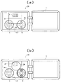
図5は、本発明の第2の実施形態を示している。図5に示す充給電装置としての充給電部26は、第1の実施形態で示した充給電部3と比較すると、コンセント4を覆うカバー27、普通充電インレット5を覆うカバー28、急速充電インレット6を覆うカバー29を有する点においてのみ相違しており、駆動システム20の制御ブロック図も含む他の構成は同一である。
FIG. 5 shows a second embodiment of the invention. As compared with the charging/
各カバー27,28,29は、それぞれの一部を収容部17に支持されて回動可能に構成されており、図示しないばね及びクリック機構により、使用可能位置である開放位置と使用不可位置である閉塞位置とを選択的に占めるように、開閉可能に構成されている。
図5(a)はカバー27が開放位置を占めた状態を示しており、この状態ではカバー27が各カバー28,29を覆う位置を占めるため、各カバー28,29の開放が禁じられる。これにより各インレット5,6の使用が禁止され、充電回路が遮断された状態となる。
図5(b)はカバー29が開放位置を占めた状態を示しており、この状態ではカバー29が各カバー27を覆う位置を占めるため、カバー27の開放が禁じられる。これによりコンセント4の使用が禁止され、給電回路が遮断された状態となる。
Each of the
FIG. 5(a) shows a state in which the
FIG. 5(b) shows a state in which the
また、各カバー27,28,29には、各カバー27,28,29を閉塞位置で保持して開放を禁止する図示しないロック機構がそれぞれ設けられており、カバー27のロック機構は始動スイッチ8がオン状態時に解除され、各カバー28,29のロック機構は始動スイッチ8がオフ状態時に解除されるように構成されている。
この構成により、始動スイッチ8の状態に応じて各カバー27,28,29のうち開放可能なカバーが選択されるため、始動スイッチ8の状態に応じて給電動作と充電動作とを選択的に行うことができ、第1の実施形態と同様の作用効果を得ることができる。
Each
With this configuration, an openable cover is selected from among the
なお、本実施形態ではカバー27の開放時に他のカバー28,29の開放を禁止する位置を占める構成としたが、ロック機構が働いていれば他のカバーの開放は禁止されているので、必ずしもこの構成には限られない。
また、本実施形態では各カバー27,28,29がそれぞれ収容部17に回動自在に支持される構成としたが、各カバー27,28,29が収容部17にそれぞれスライド自在に支持される構成としてもよい。この構成の場合には、各カバー27,28,29を開放位置に向けて平面的にスライド移動させる際に他のカバーに干渉するため、他のカバーの厚み分だけ上方に移動させつつスライドさせる構成とすることにより、他のカバーとの干渉を防止することができる。
さらに本発明の各実施形態によれば、ECU9が駆動システム20の起動状態時に給電動作を優先させるのでECU9が残充電量情報を得ることができ、駆動システム20の停止状態時に充電動作を優先させるので充電量不足の発生を防止することができる。
In this embodiment, when the
Further, in the present embodiment, each
Furthermore, according to each embodiment of the present invention, the ECU 9 gives priority to the power supply operation when the
以上、本発明の好ましい実施の形態について説明したが、本発明は上述した特定の実施形態に限定されるものではなく、上述の説明で特に限定していない限り、特許請求の範囲に記載された本発明の趣旨の範囲内において、種々の変形・変更が可能である。
例えば、上述した各実施形態では、給電回路23と充電回路24,25との何れか一方しか使用できないように他方を物理的に遮蔽する構成を示したが、他方を電気的に遮蔽する構成を採用してもよい。
一例として、レディオン状態では普通充電インレット5のコンタクタ19及び急速充電インレット6のコンタクタ16は接続されず、コンセント4のコンタクタ18が接続されて給電が優先される構成とし、レディオフ状態ではコンタクタ19及びコンタクタ16は接続し、コンタクタ18は接続されずに充電が優先される構成が挙げられる。
この場合、レディオフ状態で充電用のコネクタが接続されることになるが、使用者が車両1を発進させようとしたとき充電が行われていないために異常に気付くことができる。
なお、上述した各実施形態では給電回路23と充電回路24,25とを別々の構成としたが、電気的に遮蔽するのであれば共用する構成としてもよい。
Although the preferred embodiments of the present invention have been described above, the present invention is not limited to the specific embodiments described above, and unless otherwise limited in the above description, is set forth in the appended claims. Various modifications and changes are possible within the scope of the present invention.
For example, in the above-described embodiments, only one of the
As an example, in the ready-on state, the
In this case, the connector for charging is connected in the ready-off state, but when the user tries to start the vehicle 1, charging is not being performed, so the user can notice the abnormality.
In each of the above-described embodiments, the
また、給電回路23と充電回路24,25とを同時に使用可能な構成としてもよい。例えば、レディオン状態において給電量が充電量を上回るように給電を優先すれば駆動用バッテリ10の容量減少を遅くすることができ、ハイブリッド車ではエンジンの起動を遅らせることができる。
また、レディオフ状態において充電量が給電量を上回るように充電を優先すれば駆動用バッテリ10の容量減少を気にすることなく外部機器を使用することができる。なお、給電量と充電量との大小関係は単位時間当たりの電力量で差を設けてもよく、給電時間と充電時間とで差を設けてもよい。
本発明の実施の形態に記載された効果は本発明から生じる最も好適な効果を列挙したに過ぎず、本発明による効果は本発明の実施の形態に記載されたものに限定されるものではない。
Further, the
Also, if priority is given to charging so that the amount of charge exceeds the amount of power supply in the ready-off state, external devices can be used without worrying about a decrease in the capacity of the driving
The effects described in the embodiments of the present invention are merely enumerations of the most suitable effects resulting from the present invention, and the effects of the present invention are not limited to those described in the embodiments of the present invention. .
1・・・車両、2・・・車体、3,26・・・充給電装置(充給電部)、4・・・給電部(コンセント)、5・・・充電部(普通充電インレット)、6・・・充電部(急速充電インレット)、8・・・切替手段(始動スイッチ)、9・・・制御手段(ECU)、10・・・バッテリ(駆動用バッテリ)、12・・・モータ(駆動モータ)、20・・・駆動システム、22・・・移動手段(モータ)、23・・・給電回路、24,25・・・充電回路 DESCRIPTION OF SYMBOLS 1... vehicle, 2... vehicle body, 3, 26... charging/feeding device (charging/feeding section), 4... feeding section (outlet), 5... charging section (ordinary charging inlet), 6 . motor), 20... drive system, 22... moving means (motor), 23... feeding circuit, 24, 25... charging circuit
Claims (2)
前記駆動システムの状態を起動状態または停止状態に切り替える切替手段と、
外部機器を接続され、前記バッテリの充給電を行う充給電部とを備えた車両において、
前記充給電部は、
前記外部機器から前記バッテリに充電する充電回路と、
前記充電回路に設けられ、前記外部機器と接続可能な充電部と、
前記バッテリから前記外部機器に電力を取り出す給電回路と、
前記給電回路に設けられ、前記外部機器と接続可能な給電部と、を有し、
前記駆動システムが前記起動状態のとき前記給電回路を優先させ、前記駆動システムが前記停止状態のとき前記充電回路を優先させる制御手段を備え、
前記起動状態のとき前記充電部と重なる位置にスライド移動して前記給電部を露出すると共に前記充電部を遮蔽し、前記停止状態のとき前記給電部と重なる位置にスライド移動して前記給電部を遮蔽すると共に前記充電部を露出するカバーを有することを特徴とする車両。 a drive system having a motor and a battery, and controlling the motor and the battery;
a switching means for switching the state of the drive system between an active state and a stopped state;
A vehicle equipped with a charging and power supply unit that is connected to an external device and charges and powers the battery,
The charging power supply unit
a charging circuit that charges the battery from the external device;
a charging unit provided in the charging circuit and connectable to the external device;
a power supply circuit for extracting power from the battery to the external device;
a power supply unit provided in the power supply circuit and connectable to the external device;
control means for giving priority to the power supply circuit when the drive system is in the activated state and giving priority to the charging circuit when the drive system is in the stopped state ;
In the activated state, the power supply unit is slid to a position overlapping with the charging unit to expose the power supply unit and the charging unit is shielded. A vehicle comprising a cover that shields and exposes the charging portion .
前記駆動システムの状態を起動状態または停止状態に切り替える切替手段と、
外部機器を接続され、前記バッテリの充給電を行う充給電部とを備えた車両において、
前記充給電部は、
前記外部機器から前記バッテリに充電する充電回路と、
前記充電回路に設けられ、前記外部機器と接続可能な充電部と、
前記バッテリから前記外部機器に電力を取り出す給電回路と、
前記給電回路に設けられ、前記外部機器と接続可能な給電部と、を有し、
前記駆動システムが前記起動状態のとき前記充電回路を遮断すると共に前記給電回路を優先させ、前記駆動システムが前記停止状態のとき前記給電回路を遮断すると共に前記充電回路を優先させる制御手段を備え、
前記起動状態のとき前記充電部を遮蔽すると共に前記給電部を露出し、前記停止状態のとき前記充電部を露出すると共に前記給電部を遮蔽する移動手段と、
前記給電部を支持し、前記移動手段によって移動されるコンセント支持部材とを有し、
前記移動手段は前記起動状態のとき前記コンセント支持部材を前記充電部と重なる位置に移動させることを特徴とする車両。 a drive system having a motor and a battery, and controlling the motor and the battery;
a switching means for switching the state of the drive system between an active state and a stopped state;
A vehicle equipped with a charging and power supply unit that is connected to an external device and charges and powers the battery,
The charging power supply unit
a charging circuit that charges the battery from the external device;
a charging unit provided in the charging circuit and connectable to the external device;
a power supply circuit for extracting power from the battery to the external device;
a power supply unit provided in the power supply circuit and connectable to the external device;
control means for interrupting the charging circuit and giving priority to the power supply circuit when the drive system is in the activated state, and interrupting the power supply circuit and giving priority to the charging circuit when the drive system is in the stopped state;
a moving means that shields the charging unit and exposes the power supply unit in the activated state, and exposes the charging unit and shields the power supply unit in the stopped state;
an outlet support member that supports the power supply unit and is moved by the moving means;
The vehicle, wherein the moving means moves the outlet supporting member to a position overlapping with the charging portion in the activated state .
Priority Applications (1)
| Application Number | Priority Date | Filing Date | Title |
|---|---|---|---|
| JP2018109549A JP7187828B2 (en) | 2018-06-07 | 2018-06-07 | vehicle |
Applications Claiming Priority (1)
| Application Number | Priority Date | Filing Date | Title |
|---|---|---|---|
| JP2018109549A JP7187828B2 (en) | 2018-06-07 | 2018-06-07 | vehicle |
Publications (2)
| Publication Number | Publication Date |
|---|---|
| JP2019213406A JP2019213406A (en) | 2019-12-12 |
| JP7187828B2 true JP7187828B2 (en) | 2022-12-13 |
Family
ID=68847070
Family Applications (1)
| Application Number | Title | Priority Date | Filing Date |
|---|---|---|---|
| JP2018109549A Active JP7187828B2 (en) | 2018-06-07 | 2018-06-07 | vehicle |
Country Status (1)
| Country | Link |
|---|---|
| JP (1) | JP7187828B2 (en) |
Families Citing this family (1)
| Publication number | Priority date | Publication date | Assignee | Title |
|---|---|---|---|---|
| CN115742783B (en) * | 2021-09-03 | 2025-08-05 | 比亚迪股份有限公司 | Distributor, vehicle charging and distribution system, vehicle and charging pile |
Citations (10)
| Publication number | Priority date | Publication date | Assignee | Title |
|---|---|---|---|---|
| JP2008162543A (en) | 2007-01-04 | 2008-07-17 | Toyota Motor Corp | Hybrid vehicle |
| JP2009062027A (en) | 2007-08-10 | 2009-03-26 | Toyota Motor Corp | vehicle |
| JP2009225587A (en) | 2008-03-17 | 2009-10-01 | Toyota Motor Corp | Electric vehicle |
| JP2009273297A (en) | 2008-05-09 | 2009-11-19 | Honda Motor Co Ltd | Cyclone converter generator |
| DE102011006633A1 (en) | 2010-09-15 | 2012-03-15 | Kiekert Ag | Motor car with hybrid drive, has connection parts provided in recess, where parts are selected from group comprising direct current and alternating current charging sockets or plugs for charging battery, and tank connecting piece |
| WO2013080273A1 (en) | 2011-11-28 | 2013-06-06 | トヨタ自動車株式会社 | Vehicle control apparatus, vehicle provided with same, and vehicle control method |
| JP2013544486A (en) | 2010-12-01 | 2013-12-12 | フオルクスヴアーゲン アクチエンゲゼルシヤフト | Charging interface for electric vehicles |
| JP2014042387A (en) | 2012-08-22 | 2014-03-06 | Toyota Motor Corp | Vehicle power control device |
| JP2015012678A (en) | 2013-06-28 | 2015-01-19 | 三菱自動車工業株式会社 | Charging and feeding device for electric vehicle |
| JP2017212162A (en) | 2016-05-27 | 2017-11-30 | 三菱自動車工業株式会社 | Vehicle exterior power supply device |
Family Cites Families (1)
| Publication number | Priority date | Publication date | Assignee | Title |
|---|---|---|---|---|
| JPH07228207A (en) * | 1994-02-16 | 1995-08-29 | Sango Co Ltd | Vehicular side step |
-
2018
- 2018-06-07 JP JP2018109549A patent/JP7187828B2/en active Active
Patent Citations (10)
| Publication number | Priority date | Publication date | Assignee | Title |
|---|---|---|---|---|
| JP2008162543A (en) | 2007-01-04 | 2008-07-17 | Toyota Motor Corp | Hybrid vehicle |
| JP2009062027A (en) | 2007-08-10 | 2009-03-26 | Toyota Motor Corp | vehicle |
| JP2009225587A (en) | 2008-03-17 | 2009-10-01 | Toyota Motor Corp | Electric vehicle |
| JP2009273297A (en) | 2008-05-09 | 2009-11-19 | Honda Motor Co Ltd | Cyclone converter generator |
| DE102011006633A1 (en) | 2010-09-15 | 2012-03-15 | Kiekert Ag | Motor car with hybrid drive, has connection parts provided in recess, where parts are selected from group comprising direct current and alternating current charging sockets or plugs for charging battery, and tank connecting piece |
| JP2013544486A (en) | 2010-12-01 | 2013-12-12 | フオルクスヴアーゲン アクチエンゲゼルシヤフト | Charging interface for electric vehicles |
| WO2013080273A1 (en) | 2011-11-28 | 2013-06-06 | トヨタ自動車株式会社 | Vehicle control apparatus, vehicle provided with same, and vehicle control method |
| JP2014042387A (en) | 2012-08-22 | 2014-03-06 | Toyota Motor Corp | Vehicle power control device |
| JP2015012678A (en) | 2013-06-28 | 2015-01-19 | 三菱自動車工業株式会社 | Charging and feeding device for electric vehicle |
| JP2017212162A (en) | 2016-05-27 | 2017-11-30 | 三菱自動車工業株式会社 | Vehicle exterior power supply device |
Also Published As
| Publication number | Publication date |
|---|---|
| JP2019213406A (en) | 2019-12-12 |
Similar Documents
| Publication | Publication Date | Title |
|---|---|---|
| EP2542439B1 (en) | Vehicle with external charging | |
| KR101440011B1 (en) | Power supply system for vehicle and vehicle including the same | |
| JP5288004B2 (en) | vehicle | |
| JP5196240B2 (en) | High voltage equipment | |
| JP5421145B2 (en) | connector | |
| WO2014020715A1 (en) | Connector for externally supplying power, vehicle, and external power supply system | |
| WO2007119874A1 (en) | Power supply device and power supply device control method | |
| WO2015071721A1 (en) | Charging and discharging system and vehicle used therein | |
| JP5387024B2 (en) | Vehicle charging cable | |
| JP7626005B2 (en) | Discharge assembly, power supply system, and power supply method | |
| WO2015071712A1 (en) | Charging and discharging system with connector lock | |
| JP7601019B2 (en) | vehicle | |
| JP7524863B2 (en) | Vehicle and power supply method | |
| JP7187828B2 (en) | vehicle | |
| JP2005143200A (en) | High voltage equipment storage box | |
| US11850958B2 (en) | Connector unit for a plug-in electrical vehicle | |
| JP2010277718A (en) | Electric vehicle charger | |
| JP6127286B2 (en) | Vehicle charging device | |
| JP2013138570A (en) | High voltage apparatus | |
| KR20120126852A (en) | Emergency power interception system for electric vehicle | |
| JP7155627B2 (en) | vehicle | |
| JP5962905B2 (en) | Vehicle power supply system | |
| JP2015115988A (en) | On-vehicle electrical equipment | |
| JP2021138212A (en) | vehicle | |
| JP7771796B2 (en) | Power Supply System |
Legal Events
| Date | Code | Title | Description |
|---|---|---|---|
| A621 | Written request for application examination |
Free format text: JAPANESE INTERMEDIATE CODE: A621 Effective date: 20210526 |
|
| A131 | Notification of reasons for refusal |
Free format text: JAPANESE INTERMEDIATE CODE: A131 Effective date: 20220621 |
|
| A521 | Request for written amendment filed |
Free format text: JAPANESE INTERMEDIATE CODE: A523 Effective date: 20220705 |
|
| A131 | Notification of reasons for refusal |
Free format text: JAPANESE INTERMEDIATE CODE: A131 Effective date: 20220913 |
|
| A521 | Request for written amendment filed |
Free format text: JAPANESE INTERMEDIATE CODE: A523 Effective date: 20221013 |
|
| TRDD | Decision of grant or rejection written | ||
| A01 | Written decision to grant a patent or to grant a registration (utility model) |
Free format text: JAPANESE INTERMEDIATE CODE: A01 Effective date: 20221101 |
|
| A61 | First payment of annual fees (during grant procedure) |
Free format text: JAPANESE INTERMEDIATE CODE: A61 Effective date: 20221114 |
|
| R151 | Written notification of patent or utility model registration |
Ref document number: 7187828 Country of ref document: JP Free format text: JAPANESE INTERMEDIATE CODE: R151 |