JP2010000548A - 複合加工機 - Google Patents
複合加工機 Download PDFInfo
- Publication number
- JP2010000548A JP2010000548A JP2008159448A JP2008159448A JP2010000548A JP 2010000548 A JP2010000548 A JP 2010000548A JP 2008159448 A JP2008159448 A JP 2008159448A JP 2008159448 A JP2008159448 A JP 2008159448A JP 2010000548 A JP2010000548 A JP 2010000548A
- Authority
- JP
- Japan
- Prior art keywords
- attachment
- axis
- sub
- stocker
- attachment head
- Prior art date
- Legal status (The legal status is an assumption and is not a legal conclusion. Google has not performed a legal analysis and makes no representation as to the accuracy of the status listed.)
- Granted
Links
- 230000014759 maintenance of location Effects 0.000 abstract 2
- 238000003860 storage Methods 0.000 abstract 2
- 230000008878 coupling Effects 0.000 description 13
- 238000010168 coupling process Methods 0.000 description 13
- 238000005859 coupling reaction Methods 0.000 description 13
- 230000002093 peripheral effect Effects 0.000 description 8
- 238000000034 method Methods 0.000 description 6
- 240000004282 Grewia occidentalis Species 0.000 description 4
- 150000001875 compounds Chemical class 0.000 description 3
- 238000003754 machining Methods 0.000 description 3
- 238000010586 diagram Methods 0.000 description 1
- 238000003801 milling Methods 0.000 description 1
Images


Landscapes
- Automatic Tool Replacement In Machine Tools (AREA)
Abstract
【解決手段】立設されたコラム3L、3R上に設けられたクロスレール5にY軸方向に移動自在なサドル7を設け、このサドル7にZ軸方向へ移動自在なラム9を設け、このラム9の先端に交換可能なアタッチメントヘッド11をA軸方向へ回転可能に設け、このアタッチメントヘッド11の先端に交換可能なサブアタッチメントヘッド13をB軸方向へ回転可能に設けてなる複合加工機1であって、前記コラム3L、3Rの一端側3Rに、前記アタッチメントヘッド11、サブアタッチメント13を交換するためのアタッチメントヘッド用ストッカ29A、29B、サブアタッチメント用ストッカ29C、29D、29Eを収納したアタッチメント自動交換装置17を備えてなることを特徴とする。
【選択図】図1
Description
前記コラムの一端側に、前記アタッチメントヘッド、サブアタッチメントを交換するためのアタッチメントヘッド用ストッカ、サブアタッチメント用ストッカを収納したアタッチメント自動交換装置を備えてなることを特徴とするものである。
3R、3L コラム
5 クロスレール
7 サドル
9 ラム
11 アタッチメントヘッド
13 サブアタッチメント
15 ワーク載置用テーブル
16 自動工具交換装置
17 アタッチメント自動交換装置
23 第1スライドベース
27A〜27E 第2スライドベース
29A アタッチメントヘッド用ストッカ
29B アングル型アタッチメントヘッド用ストッカ
29C 第1サブアタッチメント用ストッカ
29D 第2サブアタッチメント用ストッカ
29E 第3サブアタッチメント用ストッカ
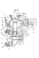
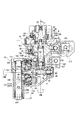
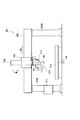
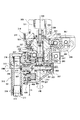
31 第1本体
33 カービックカップリング
35 第2本体
41 中空軸
43 主軸
49 入力軸
51 コレットチャック
53 プルスタッド
57 第1軸
63 クランプ筒体
65 ブッシュ
67 引っ掛かり係合部
69 コレットチャック
71 ロック部材
83 第2軸
87 第3本体
93 第3軸
105 サブアタッチメント主軸
109 サブアタッチメント本体
137 カービックカップリング
139A 凸状クランプ部
139B 被凸状クランプ部
141 スライダ
145 固定リング
Claims (4)
- 立設されたコラム上に設けられたクロスレールにY軸方向に移動自在なサドルを設け、このサドルにZ軸方向へ移動自在なラムを設け、このラムの先端に交換可能なアタッチメントヘッドをA軸回りに回転可能に設け、このアタッチメントヘッドの先端に交換可能なサブアタッチメントをB軸回りに回転可能に設けてなる複合加工機であって、
前記コラムの一端側に、前記アタッチメントヘッド、サブアタッチメントを交換するためのアタッチメントヘッド用ストッカ、サブアタッチメント用ストッカを収納したアタッチメント自動交換装置を備えてなることを特徴とする複合加工機。 - 前記アタッチメント自動交換装置が、前記コラムの一端側の外側にX軸方向に延伸して設けられたベースと、このベース上にX軸方向に設けられた移動可能な第1スライドベースと、この第1スライドベース上に設けられた、一端側上にアタッチメントヘッド用ストッカ、サブアタッチメント用ストッカを備えたY軸方向に移動可能な第2スライドベースと、からなることを特徴とする請求項1記載の複合加工機。
- 前記アタッチメントヘッド用ストッカ、サブアタッチメント用ストッカを備えた第2スライドベースが、複数個備えられていることを特徴とする請求項1または2記載の複合加工機。
- 前記アタッチメント自動交換装置の自動交換位置が、第2スライドベースの一端側上に備えたアタッチメントヘッド用ストッカ、サブアタッチメント用ストッカを前記コラムの一端側の内側であって、しかも、前記ラムの中心位置が通るクロスレールに平行な位置であることを特徴とする請求項1、2または3記載の複合加工機。
Priority Applications (1)
| Application Number | Priority Date | Filing Date | Title |
|---|---|---|---|
| JP2008159448A JP5193697B2 (ja) | 2008-06-18 | 2008-06-18 | 複合加工機 |
Applications Claiming Priority (1)
| Application Number | Priority Date | Filing Date | Title |
|---|---|---|---|
| JP2008159448A JP5193697B2 (ja) | 2008-06-18 | 2008-06-18 | 複合加工機 |
Publications (2)
| Publication Number | Publication Date |
|---|---|
| JP2010000548A true JP2010000548A (ja) | 2010-01-07 |
| JP5193697B2 JP5193697B2 (ja) | 2013-05-08 |
Family
ID=41582684
Family Applications (1)
| Application Number | Title | Priority Date | Filing Date |
|---|---|---|---|
| JP2008159448A Active JP5193697B2 (ja) | 2008-06-18 | 2008-06-18 | 複合加工機 |
Country Status (1)
| Country | Link |
|---|---|
| JP (1) | JP5193697B2 (ja) |
Citations (2)
| Publication number | Priority date | Publication date | Assignee | Title |
|---|---|---|---|---|
| JPS59182038A (ja) * | 1983-03-29 | 1984-10-16 | Toshiba Mach Co Ltd | 工作機械のサドル構造 |
| JPH04275895A (ja) * | 1991-02-26 | 1992-10-01 | Satake Eng Co Ltd | 畳表の切断装置 |
-
2008
- 2008-06-18 JP JP2008159448A patent/JP5193697B2/ja active Active
Patent Citations (2)
| Publication number | Priority date | Publication date | Assignee | Title |
|---|---|---|---|---|
| JPS59182038A (ja) * | 1983-03-29 | 1984-10-16 | Toshiba Mach Co Ltd | 工作機械のサドル構造 |
| JPH04275895A (ja) * | 1991-02-26 | 1992-10-01 | Satake Eng Co Ltd | 畳表の切断装置 |
Also Published As
| Publication number | Publication date |
|---|---|
| JP5193697B2 (ja) | 2013-05-08 |
Similar Documents
| Publication | Publication Date | Title |
|---|---|---|
| JP4340739B2 (ja) | 工作機械のパレット交換装置および工作機械 | |
| JP5385675B2 (ja) | 旋削加工用工作機械 | |
| JP5328782B2 (ja) | 工作機械 | |
| JP5026884B2 (ja) | 自動工具交換装置を有する工作機械 | |
| JP2008272889A (ja) | 工作機械 | |
| US20080254959A1 (en) | Universal head and machine tool with universal head | |
| JP2007000966A (ja) | 工作機械 | |
| DE102018002518B4 (de) | Werkzeugmaschinensystem und Bewegungsverfahren | |
| JPH058136A (ja) | 複数の加工要素を持つ加工システム | |
| JPWO2008099956A1 (ja) | 工作機械 | |
| JP2010142906A (ja) | 複合工作機械及びワークの加工方法 | |
| JP2014087865A (ja) | 旋盤およびワークの加工方法 | |
| JP5968000B2 (ja) | 歯車加工機械 | |
| JP2007229892A (ja) | ワーク位置決めテーブル | |
| JP2007075995A (ja) | 工作機械 | |
| JP5843452B2 (ja) | ロボットおよびワーク加工システム | |
| JP2004066430A (ja) | 複合工作機械 | |
| KR101257568B1 (ko) | 백보링 가공이 가능한 절삭용 가공장치 | |
| JP5474266B1 (ja) | 工作機械の内径旋削アタッチメント | |
| JP3985998B2 (ja) | 複合加工用工作機械 | |
| JP5193697B2 (ja) | 複合加工機 | |
| JP5887158B2 (ja) | 加工工具および工作機械 | |
| JPH11197982A (ja) | 工作機械のカッタ自動交換装置 | |
| JP5171111B2 (ja) | パレット交換装置 | |
| WO2018179412A1 (ja) | 工作機械 |
Legal Events
| Date | Code | Title | Description |
|---|---|---|---|
| A621 | Written request for application examination |
Free format text: JAPANESE INTERMEDIATE CODE: A621 Effective date: 20110425 |
|
| A977 | Report on retrieval |
Free format text: JAPANESE INTERMEDIATE CODE: A971007 Effective date: 20121220 |
|
| TRDD | Decision of grant or rejection written | ||
| A01 | Written decision to grant a patent or to grant a registration (utility model) |
Free format text: JAPANESE INTERMEDIATE CODE: A01 Effective date: 20130108 |
|
| A61 | First payment of annual fees (during grant procedure) |
Free format text: JAPANESE INTERMEDIATE CODE: A61 Effective date: 20130204 |
|
| R150 | Certificate of patent or registration of utility model |
Ref document number: 5193697 Country of ref document: JP Free format text: JAPANESE INTERMEDIATE CODE: R150 Free format text: JAPANESE INTERMEDIATE CODE: R150 |
|
| FPAY | Renewal fee payment (event date is renewal date of database) |
Free format text: PAYMENT UNTIL: 20160208 Year of fee payment: 3 |
|
| S533 | Written request for registration of change of name |
Free format text: JAPANESE INTERMEDIATE CODE: R313533 |
|
| R350 | Written notification of registration of transfer |
Free format text: JAPANESE INTERMEDIATE CODE: R350 |