JP2009530819A - Pressure control method and apparatus in electronic device manufacturing system - Google Patents
Pressure control method and apparatus in electronic device manufacturing system Download PDFInfo
- Publication number
- JP2009530819A JP2009530819A JP2009500452A JP2009500452A JP2009530819A JP 2009530819 A JP2009530819 A JP 2009530819A JP 2009500452 A JP2009500452 A JP 2009500452A JP 2009500452 A JP2009500452 A JP 2009500452A JP 2009530819 A JP2009530819 A JP 2009530819A
- Authority
- JP
- Japan
- Prior art keywords
- electronic device
- device manufacturing
- pump
- parameter
- manufacturing system
- Prior art date
- Legal status (The legal status is an assumption and is not a legal conclusion. Google has not performed a legal analysis and makes no representation as to the accuracy of the status listed.)
- Pending
Links
Images


Classifications
-
- F—MECHANICAL ENGINEERING; LIGHTING; HEATING; WEAPONS; BLASTING
- F04—POSITIVE - DISPLACEMENT MACHINES FOR LIQUIDS; PUMPS FOR LIQUIDS OR ELASTIC FLUIDS
- F04B—POSITIVE-DISPLACEMENT MACHINES FOR LIQUIDS; PUMPS
- F04B49/00—Control, e.g. of pump delivery, or pump pressure of, or safety measures for, machines, pumps, or pumping installations, not otherwise provided for, or of interest apart from, groups F04B1/00 - F04B47/00
- F04B49/06—Control using electricity
-
- F—MECHANICAL ENGINEERING; LIGHTING; HEATING; WEAPONS; BLASTING
- F04—POSITIVE - DISPLACEMENT MACHINES FOR LIQUIDS; PUMPS FOR LIQUIDS OR ELASTIC FLUIDS
- F04B—POSITIVE-DISPLACEMENT MACHINES FOR LIQUIDS; PUMPS
- F04B49/00—Control, e.g. of pump delivery, or pump pressure of, or safety measures for, machines, pumps, or pumping installations, not otherwise provided for, or of interest apart from, groups F04B1/00 - F04B47/00
-
- G—PHYSICS
- G05—CONTROLLING; REGULATING
- G05D—SYSTEMS FOR CONTROLLING OR REGULATING NON-ELECTRIC VARIABLES
- G05D16/00—Control of fluid pressure
- G05D16/20—Control of fluid pressure characterised by the use of electric means
Abstract
一態様において、電子デバイス製造システムにおいて圧力を制御する改善された方法及び装置が提供される。本方法は、電子デバイス製造システムの現在の状況に関連する情報を取得する工程と、取得した情報に基づいて、電子デバイス製造システムの第1のパラメータの所望の値を求める工程と、ポンプの少なくとも1つのパラメータを調整して、電子デバイス製造システムの第1のパラメータの所望の値を得る工程とを含む。 In one aspect, an improved method and apparatus for controlling pressure in an electronic device manufacturing system is provided. The method includes obtaining information related to the current status of the electronic device manufacturing system, determining a desired value of the first parameter of the electronic device manufacturing system based on the acquired information, and at least a pump Adjusting one parameter to obtain a desired value for the first parameter of the electronic device manufacturing system.
Description
本出願は、2006年3月16日に「電子デバイス製造システムにおける圧力制御方法及び装置」の名称で出願された米国特許仮出願第60/783,374号(代理人整理番号9138/L)、2006年3月16日に「電子デバイス製造システムの操作を改善する方法及び装置」の名称で出願された米国特許仮出願第60/783,370号(代理人整理番号9137/L)、2007年2月19日に「電子デバイス製造のためのハイブリッドライフサイクルインベントリー方法及び装置」の名称で出願された米国特許仮出願第60/890,609号(代理人整理番号9137/L2)、及び2006年3月16日に「軽減システムの改善された操作方法及び装置」の名称で出願された米国特許仮出願第号60/783,337号(代理人整理番号9139/L)に基づく優先権を主張する。これらの出願は引用により全体として全ての目的のため本明細書に一体化される。 This application is filed on March 16, 2006 under the name of “Method and Apparatus for Controlling Pressure in an Electronic Device Manufacturing System”, US Provisional Application No. 60 / 783,374 (Attorney Docket No. 9138 / L), US Provisional Patent Application No. 60 / 783,370 (Attorney Docket No. 9137 / L), filed March 16, 2006, under the name "Method and Apparatus for Improving Operation of Electronic Device Manufacturing System", 2007 US Provisional Patent Application No. 60 / 890,609 (Attorney Docket No. 9137 / L2) filed February 19 under the name of “Hybrid Lifecycle Inventory Method and Apparatus for Electronic Device Manufacturing”, and 2006 U.S. Provisional Patent Application No. 60 / 783,337, filed March 16 under the name "Improved Operation Method and Apparatus for Mitigation System" Claims priority based on human Docket No. 9139 / L). These applications are incorporated herein by reference in their entirety for all purposes.
本出願は、同一人に譲渡される同時係属中の下記の米国特許出願に関連し、これらの出願は引用により全体として全ての目的のため本明細書に一体化される。 This application is related to the following co-pending US patent applications assigned to the same person, which are hereby incorporated by reference in their entirety for all purposes.
「電子デバイス製造システムの操作を改善する方法及び装置」の名称で出願された米国特許出願(代理人整理番号9137/AGS/IBSS)。 US patent application (Attorney Docket No. 9137 / AGS / IBSS) filed under the title “Method and Apparatus for Improving Operation of Electronic Device Manufacturing Systems”.
「軽減システムの改善された操作方法及び装置」の名称で出願された米国特許出願(代理人整理番号9139/AGS/IBSS)。 US patent application (Attorney Docket No. 9139 / AGS / IBSS) filed under the name "Improved operating method and apparatus of mitigation system".
本発明は、概して、電子デバイス製造システムに関し、特に、電子デバイス製造システムにおける圧力制御の改善された方法及び装置に関する。 The present invention relates generally to electronic device manufacturing systems, and more particularly to an improved method and apparatus for pressure control in electronic device manufacturing systems.
電子デバイス製造ツールは、従来から、電子デバイスを製造するためのプロセス(例えば、化学気相蒸着、エピタキシャルシリコン成長、エッチング等)を行うよう適合されたプロセスチャンバ又はその他好適な装置を利用している。かかるプロセスでは、プロセスの副生成物として望ましくない化学物質を含む流出物が生成される。ポンプ(例えば、真空ポンプ)を用いて、流出物をプロセスチャンバから除去し、プロセスチャンバを真空にしてもよい。 Electronic device manufacturing tools conventionally utilize a process chamber or other suitable apparatus adapted to perform processes for manufacturing electronic devices (eg, chemical vapor deposition, epitaxial silicon growth, etching, etc.). . Such a process produces an effluent containing undesirable chemicals as a by-product of the process. A pump (eg, a vacuum pump) may be used to remove effluent from the process chamber and evacuate the process chamber.
プロセスチャンバ内の圧力を調節するために、1つ以上の追加のコンポーネントをプロセスチャンバに結合してもよい(例えば、スロットルバルブ、ゲートバルブ等)。これらのコンポーネントも、プロセスチャンバから出る流出物(例えば、流体、ガス、エマルジョン等)の流れを調節し、製造システムで行われるプロセス及び/又は他のコンポーネントに悪影響を及ぼす恐れがある。従って、電子デバイス製造システムにおける圧力制御方法及び装置を改善する必要がある。 One or more additional components may be coupled to the process chamber (eg, throttle valve, gate valve, etc.) to regulate the pressure in the process chamber. These components also regulate the flow of effluent (eg, fluids, gases, emulsions, etc.) exiting the process chamber and can adversely affect processes and / or other components performed in the manufacturing system. Accordingly, there is a need to improve pressure control methods and apparatus in electronic device manufacturing systems.
本発明の第1の態様において、電子デバイス製造システムにおいて圧力を調節する第1の方法が提供される。本方法の実施形態は、(1)電子デバイス製造システムの現在の状況に関連する情報を取得する工程と、(2)取得した情報に基づいて、電子デバイス製造システムの第1のパラメータの所望の値を求める工程と、(3)ポンプの少なくとも1つのパラメータを調整して、電子デバイス製造デバイスの第1のパラメータの所望の値を得る工程とを含む。 In a first aspect of the invention, a first method for adjusting pressure in an electronic device manufacturing system is provided. An embodiment of the method includes (1) obtaining information related to the current status of the electronic device manufacturing system, and (2) based on the obtained information, a desired parameter of the first parameter of the electronic device manufacturing system. Determining a value; and (3) adjusting at least one parameter of the pump to obtain a desired value of the first parameter of the electronic device manufacturing device.
本発明の他の態様において、電子デバイス製造ツールとポンプとを含む電子デバイス製造システムに、保守を行う方法が提供される。本方法の実施形態は、(1)電子デバイス製造ツール及びポンプの現在の状況に関連する情報を取得する工程と、(2)電子デバイス製造ツール及びポンプの現在の状況に関連する情報を処理する工程と、(3)処理された情報に基づいて、ポンプにとっての予測保守の必要性を判断する工程とを含む。 In another aspect of the present invention, a method is provided for performing maintenance on an electronic device manufacturing system that includes an electronic device manufacturing tool and a pump. Embodiments of the method include (1) obtaining information related to the current status of the electronic device manufacturing tool and pump, and (2) processing information related to the current status of the electronic device manufacturing tool and pump. And (3) determining the necessity of predictive maintenance for the pump based on the processed information.
本発明の第3の態様において、ポンプを含む電子デバイス製造システムにおいて、対応の真空ラインパラメータを平衡させる方法が提供される。本方法の実施形態は、(1)第2の真空ラインのパラメータに関連する情報及び第2の真空ラインのパラメータに関連する情報を取得する工程と、(2)第1の真空ラインのパラメータに関連する情報を、第2の真空ラインのパラメータに関連する情報と比較する工程と、(3)ポンプの少なくとも1つのパラメータを調整して、第1と第2の真空ラインの対応するパラメータを平衡させる工程とを含む。 In a third aspect of the invention, a method is provided for balancing corresponding vacuum line parameters in an electronic device manufacturing system including a pump. Embodiments of the method include (1) obtaining information related to parameters of the second vacuum line and information related to parameters of the second vacuum line; and (2) parameters of the first vacuum line. Comparing related information with information related to parameters of the second vacuum line; and (3) adjusting at least one parameter of the pump to balance the corresponding parameters of the first and second vacuum lines. And a step of causing.
本発明の第4の態様において、電子デバイス製造システムが提供され、(1)プロセスチャンバを有する電子デバイス製造ツールと、(2)プロセスチャンバに結合したポンプと、(3)電子デバイス製造ツール及びポンプから現在の状況パラメータ情報を受信し、操作を調整するよう適合された、電子デバイス製造ツール及びポンプに通信するように結合され、電子デバイス製造ツール又はポンプのパラメータの所望の値を得るためのインタフェースとを含む。 In a fourth aspect of the present invention, an electronic device manufacturing system is provided, (1) an electronic device manufacturing tool having a process chamber, (2) a pump coupled to the process chamber, and (3) an electronic device manufacturing tool and pump. An interface for receiving desired status parameter information of an electronic device manufacturing tool or pump, coupled to communicate with an electronic device manufacturing tool and a pump, adapted to receive current status parameter information from and to coordinate operation Including.
本発明の他の構成及び態様は、以下の詳細な説明、特許請求の範囲及び添付図面からより明らかとなる。 Other features and aspects of the present invention will become more apparent from the following detailed description, claims and accompanying drawings.
本発明は、パラメータ(例えば、ポンプ速度、パージ圧力等)を調整して、電子デバイス製造システムのプロセスチャンバにおける圧力を制御する方法及びシステムを提供する。かかる方法及び装置を利用して、チャンバ圧力を調節するのに典型的に利用される他のコンポーネントの使用を排除し、且つ/又は最適化する。例えば、チャンバ圧力を調節するのに典型的に利用されるスロットルバルブを、最適な位置とし、スロットルバルブが、プロセスチャンバのパラメータに与える潜在的な悪影響を最小にすることができる。更に、本発明を利用して、電子デバイス製造システムのコンポーネント、例えば、ポンプの保守の必要性を延ばしたり、予測することができる。 The present invention provides a method and system for adjusting parameters (eg, pump speed, purge pressure, etc.) to control pressure in a process chamber of an electronic device manufacturing system. Such methods and apparatus are utilized to eliminate and / or optimize the use of other components typically utilized to adjust chamber pressure. For example, the throttle valve typically utilized to adjust the chamber pressure can be in an optimal position to minimize the potential adverse effects that the throttle valve has on the process chamber parameters. Furthermore, the present invention can be used to extend or predict the maintenance needs of components of electronic device manufacturing systems, such as pumps.
また、本発明は、パラメータ、例えば、ポンプにより与えられる圧力を制御することにより、チャンバ間の変動を減少して、かかる変動がプロセス性能に与える影響を減じるための方法及びシステムも提供する。例えば、2つ以上のチャンバ内のスロットルバルブを略同じ位置まで開き、流出物の流れ(例えば、層流、乱流等)をチャンバ間で平衡化することができる。 The present invention also provides a method and system for controlling parameters, eg, pressure provided by a pump, to reduce variations between chambers and reduce the impact of such variations on process performance. For example, throttle valves in two or more chambers can be opened to approximately the same position to balance the effluent flow (eg, laminar flow, turbulence, etc.) between the chambers.
少なくとも1つの例示の実施形態において、チャンバに与えられる真空力は、ポンプの速度により制御される。印加された真空力の量は、フォアラインの形状、流出物の特性及び用いられるその他同様のパラメータ等のパラメータに関係する。本発明は、ポンプ速度を調整して、これら及びその他パラメータを補うものである。このようにして、チャンバ内の圧力を、ポンプにより制御することができる。ある実施形態において、スロットルバルブ位置を、全開位置に設定することができる。これによって、プロセスチャンバに粒子が蓄積するのを減らすことができる。少なくとも1つの変形実施形態において、スロットルバルブはシステムから排除することができる。 In at least one exemplary embodiment, the vacuum force applied to the chamber is controlled by the speed of the pump. The amount of applied vacuum force is related to parameters such as foreline shape, effluent characteristics and other similar parameters used. The present invention adjusts the pump speed to compensate for these and other parameters. In this way, the pressure in the chamber can be controlled by the pump. In some embodiments, the throttle valve position can be set to a fully open position. This can reduce the accumulation of particles in the process chamber. In at least one alternative embodiment, the throttle valve can be excluded from the system.
図1は、本発明の実施形態による電子デバイス製造システム100を示す概略ブロック図である。電子デバイス製造システム100は、ポンプ104に結合した電子デバイス製造ツール102と、ポンプ104から下流に結合した軽減ユニット106とを含む。電子デバイス製造ツール102は、1つ以上のプロセス(堆積、エッチング等)を基板に行うように適合されたプロセスチャンバ108と、流体ライン110を介して、プロセスチャンバ108に化学物質を分配するように適合された化学分配ユニット109(例えば、ガスパネル、スラリー分配ユニット、液体前駆体分配システム等)とを含む。化学分配ユニット109は、流体ライン110を介して、1つ以上のプロセスを実施する際、プロセスチャンバ108により利用される化学前駆体(例えば、SiH4、NF3、CF4、BCl3等)を提供する。
FIG. 1 is a schematic block diagram illustrating an electronic
プロセスチャンバ108で実施されるプロセスは、周囲圧力(例えば、1気圧(atm)等)より低い圧力で実施してよい。例えば、プロセスの中には、約8〜700ミリトル(mTorr)の圧力で実施されるものもある。これ以外の圧力を用いてもよい。他のプロセス、例えば、堆積手順の中には、8トルより低い圧力を用いるものがある。電子デバイス製造ツール102のプロセスチャンバ108は、真空ライン112を介してポンプ104に結合されていてもよい。プロセスチャンバ108内を減圧にするために、ポンプ104で、真空を適用して、プロセスチャンバ108から流出物(例えば、ガス、プラズマ等)を除去する。特に、プロセスチャンバ108から、ポンプ104に向って真空ライン112を介して、ポンプ104により作成された真空力により、流出物を引いてもよい。1つ以上の実施形態において、ポンプ104は、インペラ(例えば、ローブ、ブレード等、図示せず)等の回転可能なコンポーネントを含み、真空力は、ポンプ104に含まれるインペラの回転により生成される。ポンプ104の作用により生成される真空力及び得られる減圧は、インペラの回転速度に比例する。同様に、流出物がプロセスチャンバ108から除去される量及び/又は速度は、真空力に、従って、ポンプ104のインペラが回転する速度に比例する。インペラ回転速度は、約200〜約18000RPMまで変わる。ただし、他の回転速度を用いてもよい。
The process performed in the
ポンプ104は、管114を介して、軽減ユニット106に結合されていてもよい。軽減ユニット106は、電子デバイス製造ツール102の流出物を処理して、流出物から不純物、汚染物質及び/又は有害化学物質を除去する。軽減ユニット106は、例えば、制御された分解酸化(CDO)、ウォータースクラバー、吸収系受動樹脂、燃焼システム等を含む。本発明において用いられる例示の軽減ユニットは、カリフォルニア州、サンノゼのメトロンテクノロジー社より入手可能なマラソンシステムである。他の軽減ユニットを用いてもよい。
The
電子インタフェース116は、信号ライン120を介して、プロセスチャンバ108、化学分配ユニット109、ポンプ104及び軽減ユニット106に結合されていて、信号を受信する。インタフェース116は、アナログ及び/又はデジタル電子コンポーネント、例えば、マイクロプロセッサ、I/Oポート、モデム等を含んでおり、情報を処理し、電子デバイス製造システム100の他の部分へ/から、伝達及び受信するように適合されている。インタフェース116はまた、ホストコンピュータ、メインフレームコンピュータ、サーバ又はその他コンピュータシステムも含む。インタフェース116は、システム100の他のコンポーネント、例えば、プロセスチャンバ180で生じるプロセスに関連する情報を、信号ライン120を介して受信する。プロセスに関連する情報としては、プロセス工程時間、圧力、流体の流れ等のパラメータが挙げられる。
1つ以上の実施形態において、インタフェース116はまた、プロセス関連パラメータの既知の挙動に関連する情報を含む1つ以上のデータベースから情報も受信する。前述した一体化された米国特許出願(代理人整理番号9137)に記載されている通り、データベースには、システムパラメータが長期にわたって正確に測定される電子デバイス製造システム100と同様の設計を有する計装参照システム(図示せず)から導かれた情報が投入される。参照システムによりなされたパラメータ測定を用いて、長期にわたる1つ以上のパラメータの挙動を説明する関数(例えば、ベストフィットカーブ、正規分布等式)や、1つ以上の他のパラメータの関数を導く。これらの関数は、インタフェース116によりアクセス可能なデータベースにまとめることのできる定数を用いて記載することができる。インタフェース116は、データベース中の情報を用いて、電子デバイス製造システム100の実際のパラメータを調整するのに所望の、且つ/又は最良の値を求める。
In one or more embodiments, the
インタフェース116はまた、電子デバイス製造システム100の一部に、信号ライン120を介して、情報を提供もする。例えば、インタフェース116は、ポンプ104に情報(例えば、プロセスチャンバ108等のシステム100の他の部分から受信した情報に基づいて)を提供する。かかる情報を利用して、ポンプパラメータ、例えば、ポンプ104により印加される真空力等を調整し、電子デバイス製造システム100の圧力及びその他物理的及び/又は化学的パラメータを調節する。1つ以上の実施形態において、インタフェース116は、ポンプ104に情報を提供して、プロセスチャンバ108の圧力を所望のレベルまで修正する。
The
センサ117及び/又はコントローラ118を、電子デバイス製造ツール102(例えば、プロセスチャンバ108と化学分配ユニット109)、ポンプ104及び軽減ユニット106に結合してもよい。センサ117及び/又はコントローラ118は、電子デバイス製造システム100の様々なコンポーネント(例えば、電子デバイス製造ツール102、ポンプ、軽減ユニット106)に関する情報(例えば、状況、操作等)を、信号ライン120に沿って、インタフェース116に提供する信号を生成する。情報は、パラメータ、例えば、電子デバイス製造ツール102のプロセスチャンバ108内の圧力、ポンプ104の速度及び軽減ユニット106の特定の種類のガスの存在等に関するものである。センサの種類としては、圧力ゲージ、工程時間を測定するタイマー、電力計等が挙げられる。
情報はまた、コントローラ118(例えば、ラックマウント、ワークステーション、コントローラボード、埋め込みプロセッサ等)により、インタフェース116に提供されてもよい。コントローラ118は、情報を制御し、且つ/又は、電子デバイス製造ツール102、ポンプ104及び軽減ユニット106から(例えば、センサ117を介して)受信するように適合されている。コントローラ118は、複数のコントローラとして実装されていてもよい。例えば、プロセスチャンバ108が、第1のコントローラ118に結合され、化学分配ユニット109が、第2のコントローラ118に結合されていてもよい。或いは、単一のコントローラ118及び/又はコントローラ118のネットワークを利用して、電子デバイス製造ツール102及び/又は処理チャンバ108及び化学分配ユニット109を制御してもよい。コントローラ118により提供される情報は、コントローラ118により、電子デバイス製造システム100のコンポーネントに提供される制御信号に関するものでもよい。例えば、プロセスチャンバ108に結合したコントローラ118は、プロセスチャンバ108に信号を提供して、プロセスレシピで工程を開始してもよい。かかる情報は、インタフェース116に提供される。
Information may also be provided to interface 116 by controller 118 (eg, rack mount, workstation, controller board, embedded processor, etc.). The
電子デバイス製造ツール102内で、プロセスチャンバ108内の圧力は、流出物除去速度や流体供給速度、例えば、真空ライン112の流体伝導性とは別に更なるパラメータに影響される。真空ライン112は、限定された断面寸法及び/又はその他制限又は限定の特徴を有する。真空ライン112の流体伝導性は、真空ライン112の長さに反比例するため、プロセスチャンバ108内の圧力は、長い真空ライン112だと高くなる。かかる差は、ポンプ速度を調整することにより補正される。例えば、真空ライン112が比較的長い場合には、ポンプ104のポンプ速度を補正のために早くする。かかる圧力調節の詳細は、図6〜7を参照して後述してある。
Within the electronic
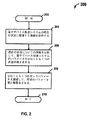
図2は、本発明により、ポンプパラメータを調整することにより、電子デバイス製造システム内の操作パラメータを調節する方法の例示の実施形態のフローチャートである。方法200は、工程202で始まる。工程204において、インタフェース116は、電子デバイス製造システム100の現在の状況に関する情報を取得する。電子デバイス製造システム100の現在の状況に関する情報としては、プロセスチャンバで実施されているプロセスの種類、及び1つ以上のセンサ117によりなされる現在の操作パラメータの測定値が挙げられる。操作パラメータとしては、例えば、プロセスチャンバ108の現在の圧力、化学分配ユニット109からの流体の流速、管114の流出物の流速等が挙げられる。工程206において、電子デバイス製造システム100の現在の状況に関する情報が分析されて、所望のパラメータ値が求められる。所望の値が求められるパラメータは、測定された操作パラメータと同じ、又は異なる。より具体的には、チャンバ圧力、ガス流速等を含む現在の操作パラメータを用いて、プロセスチャンバ108から出る流体の流れの「予測解」を生成し、これを分析して、所望のパラメータ値が決まる。所望のパラメータ値は、ローカル又はリモート参照データベース(図示せず)から得られる。これには、様々なパラメータ間の関数関係に関するデータが含まれている。
FIG. 2 is a flowchart of an exemplary embodiment of a method for adjusting operating parameters in an electronic device manufacturing system by adjusting pump parameters in accordance with the present invention.
同時に出願された、前述した一体化された米国特許出願(代理人整理番号9137)に記載されている通り、参照データベースに含まれるデータは、電子デバイス製造システム100に主に対応している参照システム(図示せず)から誘導されるが、専用の試験装置を利用して、圧力、ガス流、ガス含量等といった物理及び/又は化学パラメータに関する大量のデータを長期にわたって集めることができる。このデータを分析して、関数関係が判断される。関数関係は、パラメータ(例えば、関数方程式に当てはめられる定数)を用いて表わされ、参照データベースに組み込まれる。所望のパラメータ値が、かかる関数関係に基づいて測定値から得られる。
As described in the above-mentioned integrated US patent application (Attorney Docket No. 9137) filed at the same time, the data contained in the reference database is primarily a reference system corresponding to the electronic
図2を再び参照すると、所望のパラメータ値がいったん決まれば、工程208において、ポンプ104のパラメータを調整して、工程206で求めた所望のパラメータ値と略整合させる。例えば、ポンプ104速度を調整して、所望のパラメータ値(例えば、プロセスチャンバ208の圧力)を生成する。方法200は、工程210で終了する。
Referring again to FIG. 2, once the desired parameter value is determined, in
図3は、本発明により、ポンプ104の予防保守を最適化する方法の例示の実施形態のフローチャートである。方法300は、工程302で始まる。工程304において、電子デバイス製造ツール102及びポンプ104の現在の状況に関する情報を取得する。情報には、ポンプ速度データ、ポンプパージ圧力データ、プロセスチャンバ108に流れる流体の種類、積分された流体の流速データ等をはじめとする、ある期間にわたって記録された一連のデータが含まれる。情報の取得は、電子デバイス製造システム100のセンサ117及びコントローラ118を用いて、且つ/又は参照システム(図示せず)を用いて行われる。センサ117及び/又はコントローラ118が、インタフェース116又はその他好適な装置に、情報を提供する。
FIG. 3 is a flowchart of an exemplary embodiment of a method for optimizing preventive maintenance of
工程306において、電子デバイス製造ツール102及びポンプ104に関連する情報が蓄積され、インタフェース116又はその他好適な装置を用いて分析される。情報の分析には、ポンプ回転数、故障するまでの時間、ポンプパージ速度等の蓄積が挙げられる。かかる分析を用いて、ポンプの保守及び/又は故障についての1つ以上のパラメータに関連する蓄積された情報を補正する。分析には、実験計画(DOE)法が含まれる。少なくとも1つの実施形態において、センサ117を利用して、ポンプパラメータの性能又は出力における変化を測定することができる。例えば、音響マイクのようなセンサ117を、ベアリング又はその近傍に配置して、ベアリングが摩耗した、又は不安定になった時を「聞いて」みてもよい。性能及び/又は出力における変化は、特定の操作パラメータ、例えば、モータ電流、冷却水温度、排気圧、モータ温度、ポンプ本体温度等により相関させてよい。実験計画法を用いて、「通常の」操作範囲と、通常操作範囲を外れたことを示すものを確立してもよい。
In
工程308において、ポンプ104の保守の必要性が予測される。保守の予測は、工程306での情報の蓄積及び分析に基づいている。予測は工程306中に実施される分析の結果を、作業主(例えば、エンジニア、ワークステーション等)に知らせることによりなされ、予測の評価が可能となる。例えば、工程306で蓄積され、分析された情報は、作業主に知らせた後に更に分析して、予測を行ってもよい。ポンプ104の予測保守の必要性を利用して、ポンプの保守を予定する。加えて、ポンプ104の予測ダウンタイムを利用して、ポンプの保守の予定を最適化して、不測の故障(例えば、破壊等)を防ぐ。工程308の後、方法300は工程310で終了する。
In
図4は、本発明により、電子デバイス製造ツール102、ポンプ104及び軽減ユニット106の操作データを用いて、ポンプ104の予防保守を最適化する方法のフローチャートである。方法400は、方法300と同様であるが、軽減ユニット106から情報を得て、ポンプ104の予防保守計画を予測することが追加されている。方法400は、工程402で始まる。
FIG. 4 is a flowchart of a method for optimizing preventive maintenance of
工程404において、電子デバイス製造ツール102、ポンプ104及び軽減ユニット106に関連する情報を取得する。図3を参照して述べた情報に加えて、工程404で取得した情報には、軽減ユニット106に関連する情報が含まれる。軽減ユニット106は、電子デバイス製造ツール102により生成された流出物を希釈するのに利用される軽減プロセスに関連する情報を提供する。かかる情報は、例えば、軽減ユニットの流出ガスの温度、含量及び圧力に関するものである。
In
工程306と同様のやり方で、工程406において、工程404で取得した情報を蓄積し、分析する。工程404の蓄積及び分析には、工程304で述べた方法が含まれる。工程408において、工程308と同様のやり方で、工程406で蓄積され、分析された情報を利用して、ポンプ104の保守の必要性を予測する。工程408の後、方法400を工程410で終了する。
In a manner similar to step 306, in
図5は、本発明により、ポンプ104の少なくとも1つのパラメータを調整することにより、電子デバイス製造ツール102のプロセスチャンバ108において圧力を制御する方法の実施形態のフローチャートである。方法500は、工程502で始まる。工程504において、プロセスチャンバ108の所望の圧力を求める。所望の圧力は、電子デバイス製造システム100の1つ以上のパラメータの現在の状況から、参照データベース(図2に関して上述した通り)、プロセスレシピ等を用いて求められる。関連パラメータとしては、ポンプ104の圧力のランプレート、ランプまでの時間、真空ラインの長さ等が挙げられる。更に、又はこの代わりに、予測解を利用して、所望の圧力を求めてもよい。例えば、パラメータ(例えば、パイプ長さ、流体の流速等)を評価する予測解を利用して、プロセスチャンバ108からの流出物を予測する。流出物のパラメータの予測を利用することにより、所望の圧力を求めて、将来生じるであろうパラメータ値における変化を明らかにする。工程506において、プロセスチャンバ108の圧力を求める。工程506には、電子デバイス製造ツール102において、センサ117及び/又はコントローラ(例えば、プロセスチャンバ108)からの情報を取得することが含まれる。
FIG. 5 is a flowchart of an embodiment of a method for controlling pressure in the
工程508において、ポンプ104の速度を調整して、プロセスチャンバ108の圧力を、工程504で求めた所望の圧力と同じ、又は略同じ値になるようにする。プロセスチャンバ108の圧力は、ポンプ104により印加された真空力における変化を経て修正される。プロセスチャンバ108の圧力を修正する更なる方法及び装置を、工程508におけるポンプ104の速度に対する調整と併せて利用してもよい。例えば、プロセスチャンバ108を、1つ以上の追加の圧力調節デバイス、例えば、スロットルバルブ、追加の真空ポンプ等に結合してもよい。圧力調節デバイスは、ポンプ104と併せて、プロセスチャンバ108の圧力を修正して、所望の圧力と同じ又は略同じ値になるようする。工程510において、ポンプ速度に対する調整により、プロセスチャンバ208において所望の圧力が十分に得られたかどうか確認する。プロセスチャンバ108の圧力が、所望の圧力と略同じでない場合には、方法500は、工程506に戻る。プロセスチャンバ108の圧力が、所望の圧力と略同じ場合には、方法500を工程502に進め、方法500を終了する。
In
図6は、第1の組と第2の組の少なくとも1対の同様のパラメータが、本発明により最適に整合された第1及び第2組のプロセスチャンバ、真空ライン、ポンプ、管及び軽減ユニットを含む電子デバイス製造システム600の例示の実施形態の概略ブロック図である。図6に示す通り、デュアル電子デバイス製造システム600は、デュアル電子デバイス製造ツール102’を含む。電子デバイス製造システム600はまた、第1のポンプ104A、第1の軽減ユニット106A、第1のプロセスチャンバ108A、第1の真空ライン110A、第1の管112A、第1の化学分配ユニット114A及び第1の流体ライン116Aを含む第1の組のデバイス602も含む。また、電子デバイス製造システム600は、第2のポンプ104B、第2の軽減ユニット106B、第2のプロセスチャンバ108B、第2の真空ライン110B、第2の管112B、第2の化学分配ユニット114B及び第2の流体ライン116Bを含む第2の組のデバイス604も含む。
FIG. 6 shows first and second sets of process chambers, vacuum lines, pumps, tubes and mitigation units in which at least one pair of similar parameters of the first set and the second set are optimally matched according to the present invention. 1 is a schematic block diagram of an exemplary embodiment of an electronic
第1の組のデバイス602と第2の組のデバイス604は、同様の種類のコンポーネントを含み、直接対比される同様の操作パラメータを有している。例えば、第1のポンプ104Aは、第1のポンプ速度を有している。第2のポンプ104Bは、第2のポンプ速度を有している。このように、本実施形態において、第1及び第2のポンプ速度は、同様の匹敵するパラメータである。
The first set of
第1の組のデバイス602に関して、第1のポンプ104Aは、第1の真空ライン110Aを介して、第1のプロセスチャンバ108Aに結合されており、第1の化学分配ユニット114Aは、第1の流体ライン116Aを介して、第1のプロセスチャンバ108Aに結合されており、第1の軽減ユニット106Aは、第1の管112Aを介して、第1のポンプ104Aに結合されている。同様に、第2の組のデバイス604において、第2のポンプ104Bは、第2の真空ライン110Bを介して、第2のプロセスチャンバ108Bに結合されており、第2の化学分配ユニット114Bは、第2の流体ライン116Bを介して、第2のプロセスチャンバ108Bに結合されており、第2の軽減ユニット106Bは、第2の管112Bを介して、第2のポンプ104Bに結合されている。
With respect to the first set of
第1の真空ライン110A及び第2の真空ライン110Bは、真空ライン110A及び110Bの流体伝導性に影響する異なるパラメータを有している。真空ライン110A及び110Bの伝導性に影響するパラメータとしては、真空ライン110A及び110Bの幅、形状、材料等が挙げられる。例えば、図6に示す通り、第2の真空ライン110Bは、第1の真空ライン110Aとは異なる形状(例えば、長い、曲がっている、等)を有していてもよい。真空ライン110Aと110Bの間の圧力差は、真空ライン110A及び110Bの長さの差に比例する。より具体的には、真空ライン110Aと110Bの圧力は、位置606A及び606B近くで略等しく、位置608A及び608Bで異なっていてもよい。例えば、位置608Aの圧力は、位置608Bの圧力より低い。しかしながら、ポンプ104A及び104Bを利用して、圧力差を補正することにより、位置608A及び608Bの圧力は平衡する。
The
図7は、第1及び第2の真空ラインの少なくとも1つのパラメータを、本発明により平衡化されるように、電子デバイス製造システム600の第1及び第2のポンプの少なくとも1つのパラメータを調整する方法のフローチャートである。
FIG. 7 adjusts at least one parameter of the first and second pumps of the electronic
方法700は、工程702で始まる。工程704において、第1の真空ライン110A及び第2の真空ライン110Bのパラメータに関連する情報を取得する。情報は、第1の真空ライン110A及び第2の真空ライン110Bにおける流出物の圧力、化学組成、粘度等に関連している。情報は、第1及び第2の真空ライン110A、110Bに結合したセンサ及び/又はコントローラ(図示せず)により提供されてもよい。
工程706において、真空ライン110A及び110Bのパラメータ情報を比較する。例えば、位置608A及び608Bの圧力を比較する。工程708において、少なくとも1つのポンプパラメータを調整して、第1の真空ライン110A及び第2の真空ライン110Bの少なくとも1対の対応するパラメータが平衡するようにする(例えば、真空ライン110A、110Bに沿って対応する点608A、608Bでの圧力)。方法700は、工程710で終了する。
In
図8は、プロセスチャンバ108に結合したスロットルバルブ802を有する装置800を示す概略ブロック図であって、スロットルバルブのプロセスチャンバのパラメータに与える影響を、本発明により最小にしたものである。装置800は、スロットルバルブ802を介して、真空ライン110に結合したポンプ104を有している。スロットルバルブ802は、モータ806に回転可能に結合した羽根804を含む。モータ806はまた、スロットルバルブ802に結合されていてもよい。図1を参照して説明した装置100と同様に、真空ライン110がポンプ104に結合されていて、ポンプ104が管112を介して、軽減ユニット106に結合されていてもよい。
FIG. 8 is a schematic block diagram illustrating an
スロットルバルブ802の羽根804を利用して、プロセスチャンバ108の圧力を修正してもよい。図1を参照して説明した通り、化学分配ユニット114は、前駆体化学物質をプロセスチャンバ108に供給し、ポンプ104は、プロセスチャンバ108から流出物を除去する。羽根804は、流出物の除去を調節して、プロセスチャンバ108の圧力を調整する。例えば、一実施形態において、羽根804は、モータ806が軸周囲を回転するディスクを含む。羽根804は、全開位置から全閉位置まで、その間の任意の位置で回転できる。全閉又は部分的閉位置で、流出物の流れをプロセスチャンバ108から十分に制限して、プロセスチャンバ108の圧力を増加する。全開位置は、プロセスチャンバ内の圧力を増加しない。ただし、流出物の経路に羽根804が存在すると、プロセスチャンバ108から出る流出物の流れに名目上の影響を与え、処理チャンバ108のパラメータに影響する可能性がある。
The
ポンプ104を利用して、プロセスチャンバ108の圧力を調節するのに、スロットルバルブ802の使用を減じることができる。図5を参照して説明した通り、ポンプ104を利用して、プロセスチャンバ108の圧力を調節してもよい。スロットルバルブ802と併せてかかる方法を利用することにより、羽根804の位置を最適にする。例えば、羽根804の位置を最適にすることにより、チャンバに戻される流出物の一部を減じるのが望ましい。このように、スロットルバルブ802と併せてポンプ104を利用して、プロセスチャンバ108の圧力を制御することにより、羽根804の位置を最適にして、プロセスチャンバ108に戻される流出物の量を減じる。
The
図9は、スロットルバルブ802を本発明によって最適な位置とし、ポンプ104のパラメータを調整することにより、プロセスチャンバ108における少なくとも1つのパラメータを修正する方法のフローチャートである。プロセスチャンバ108のパラメータ(例えば、圧力、流出物の流れ、等)は、ポンプ104の少なくとも1つのパラメータを調整することにより制御してもよい。
FIG. 9 is a flow chart of a method of modifying at least one parameter in the
方法900は、工程902で始まる。工程904において、上述した通り、取得した測定値を分析する、又は長期にわたる様々なパラメータ間の既知の関数関係に基づいて、予測解を用いることにより、プロセスチャンバ108の所望の圧力を求める。工程906において、スロットルバルブ802の羽根804を、所望の圧力に基づいて、最適な位置に設定する。1つ以上の実施形態において、最適な位置は、開位置である。あるいは、最適な位置は、部分的開位置である。工程908において、プロセスチャンバ内の圧力を求める。工程910において、ポンプ速度を調整して、プロセスチャンバ内の圧力を所望の圧力に近づける。工程912において、プロセスチャンバ内の圧力をモニターして、圧力が、所望の圧力に近づいたか判断する。近づいた場合には、方法を工程914で終了し、近づいていない場合には、方法を工程906に戻って、羽根804の位置を再び調整する(例えば、実際のプロセスチャンバ圧力が所望の圧力とは異なる量に基づいて、羽根804の位置を調整する)。
前述の記載は、本発明の例示の実施形態を開示しているに過ぎない。本発明の範囲内となる上記の開示された装置及び方法の修正は、当業者には容易に明白である。例えば、上述した方法及び装置は、これらに限られるものではないが、多数のプロセスチャンバに結合した単一の軽減システム、単一のプロセスチャンバに結合した多数のポンプ、等をはじめとする多数の異なる構成のシステムに適用される。 The foregoing description merely discloses exemplary embodiments of the invention. Modifications to the above disclosed apparatus and methods that fall within the scope of the invention will be readily apparent to those skilled in the art. For example, the methods and apparatus described above are not limited to these, but include a number of systems including a single mitigation system coupled to multiple process chambers, multiple pumps coupled to a single process chamber, and the like. Applies to systems with different configurations.
従って、本発明をその例示の実施形態に関して開示してきたが、他の実施形態も特許請求の範囲基づいて定められる本発明の思想及び範囲内にあるものと考えられる。 Thus, while the invention has been disclosed with reference to exemplary embodiments thereof, other embodiments are considered to be within the spirit and scope of the invention as defined by the claims.
Claims (21)
前記電子デバイス製造システムの現在の状況に関連する情報を取得する工程と、
前記取得した情報に基づいて、前記電子デバイス製造システムの第1のパラメータの所望の値を求める工程と、
ポンプの少なくとも1つのパラメータを調整して、前記電子デバイス製造デバイスシステムの前記第1のパラメータの前記所望の値を得る工程とを含む方法。 A method for controlling pressure in an electronic device manufacturing system, comprising:
Obtaining information related to the current status of the electronic device manufacturing system;
Obtaining a desired value of the first parameter of the electronic device manufacturing system based on the acquired information;
Adjusting at least one parameter of the pump to obtain the desired value of the first parameter of the electronic device manufacturing device system.
前記電子デバイス製造ツール及びポンプの現在の状況に関連する情報を取得する工程と、
前記電子デバイス製造ツール及びポンプの前記現在の状況に関連する情報を処理する工程と、
前記処理された情報に基づいて、前記ポンプにとっての予測保守の必要性を判断する工程とを含む方法。 A method of maintaining an electronic device manufacturing system including an electronic device manufacturing tool and a pump, comprising:
Obtaining information related to the current status of the electronic device manufacturing tool and pump;
Processing information related to the current status of the electronic device manufacturing tool and pump;
Determining the need for predictive maintenance for the pump based on the processed information.
第1の真空ラインのパラメータに関連する情報及び第2の真空ラインのパラメータに関連する情報を取得する工程と、
前記第1の真空ラインの前記パラメータに関連する前記情報を、前記第2の真空ラインの前記パラメータに関連する前記情報と比較する工程と、
前記ポンプの少なくとも1つのパラメータを調整して、前記第1と第2の真空ラインの対応するパラメータを平衡させる工程とを含む方法。 In an electronic device manufacturing system including a pump, a method of balancing corresponding vacuum line parameters comprising:
Obtaining information relating to parameters of the first vacuum line and information relating to parameters of the second vacuum line;
Comparing the information related to the parameter of the first vacuum line with the information related to the parameter of the second vacuum line;
Adjusting at least one parameter of the pump to equilibrate corresponding parameters of the first and second vacuum lines.
プロセスチャンバを有する電子デバイス製造ツールと、
前記プロセスチャンバに結合したポンプと、
前記電子デバイス製造ツール及びポンプから現在の状況パラメータ情報を受信し、操作を調整するよう適合された、前記電子デバイス製造ツール及び前記ポンプに通信するように結合され、前記電子デバイス製造ツール又は前記ポンプのパラメータの所望の値を得るためのインタフェースとを含む電子デバイス製造システム。 An electronic device manufacturing system,
An electronic device manufacturing tool having a process chamber;
A pump coupled to the process chamber;
The electronic device manufacturing tool or the pump coupled to communicate with the electronic device manufacturing tool and the pump, adapted to receive current status parameter information from the electronic device manufacturing tool and pump and to adjust operation And an interface for obtaining a desired value of the parameter of the electronic device.
Applications Claiming Priority (5)
| Application Number | Priority Date | Filing Date | Title |
|---|---|---|---|
| US78337406P | 2006-03-16 | 2006-03-16 | |
| US78333706P | 2006-03-16 | 2006-03-16 | |
| US78337006P | 2006-03-16 | 2006-03-16 | |
| US89060907P | 2007-02-19 | 2007-02-19 | |
| PCT/US2007/006392 WO2007109038A2 (en) | 2006-03-16 | 2007-03-14 | Methods and apparatus for pressure control in electronic device manufacturing systems |
Publications (2)
| Publication Number | Publication Date |
|---|---|
| JP2009530819A true JP2009530819A (en) | 2009-08-27 |
| JP2009530819A5 JP2009530819A5 (en) | 2010-04-30 |
Family
ID=38522928
Family Applications (4)
| Application Number | Title | Priority Date | Filing Date |
|---|---|---|---|
| JP2009500471A Active JP6030278B2 (en) | 2006-03-16 | 2007-03-14 | Method and apparatus for improving the operation of an electronic device manufacturing system |
| JP2009500470A Active JP6034546B2 (en) | 2006-03-16 | 2007-03-14 | Method and apparatus for improved operation of mitigation system |
| JP2009500452A Pending JP2009530819A (en) | 2006-03-16 | 2007-03-14 | Pressure control method and apparatus in electronic device manufacturing system |
| JP2014165252A Active JP6182116B2 (en) | 2006-03-16 | 2014-08-14 | Method and apparatus for improving the operation of an electronic device manufacturing system |
Family Applications Before (2)
| Application Number | Title | Priority Date | Filing Date |
|---|---|---|---|
| JP2009500471A Active JP6030278B2 (en) | 2006-03-16 | 2007-03-14 | Method and apparatus for improving the operation of an electronic device manufacturing system |
| JP2009500470A Active JP6034546B2 (en) | 2006-03-16 | 2007-03-14 | Method and apparatus for improved operation of mitigation system |
Family Applications After (1)
| Application Number | Title | Priority Date | Filing Date |
|---|---|---|---|
| JP2014165252A Active JP6182116B2 (en) | 2006-03-16 | 2014-08-14 | Method and apparatus for improving the operation of an electronic device manufacturing system |
Country Status (7)
| Country | Link |
|---|---|
| US (3) | US20070256704A1 (en) |
| EP (3) | EP1994457B1 (en) |
| JP (4) | JP6030278B2 (en) |
| KR (2) | KR101126413B1 (en) |
| CN (1) | CN101495925B (en) |
| TW (3) | TWI407997B (en) |
| WO (3) | WO2007109038A2 (en) |
Cited By (2)
| Publication number | Priority date | Publication date | Assignee | Title |
|---|---|---|---|---|
| JP2012054541A (en) * | 2010-08-05 | 2012-03-15 | Ebara Corp | Exhaust system |
| JP2020031135A (en) * | 2018-08-22 | 2020-02-27 | 株式会社ディスコ | Silicon wafer processing method and plasma etching system |
Families Citing this family (26)
| Publication number | Priority date | Publication date | Assignee | Title |
|---|---|---|---|---|
| US20090175771A1 (en) * | 2006-03-16 | 2009-07-09 | Applied Materials, Inc. | Abatement of effluent gas |
| EP1994457B1 (en) | 2006-03-16 | 2012-06-13 | Applied Materials, Inc. | Method and apparatus for improved operation of an abatement system |
| US20080216901A1 (en) * | 2007-03-06 | 2008-09-11 | Mks Instruments, Inc. | Pressure control for vacuum processing system |
| WO2008147524A1 (en) * | 2007-05-25 | 2008-12-04 | Applied Materials, Inc. | Methods and apparatus for efficient operation of an abatement system |
| KR101560705B1 (en) * | 2007-05-25 | 2015-10-16 | 어플라이드 머티어리얼스, 인코포레이티드 | Methods and apparatus for assembling and operating electronic device manufacturing systems |
| WO2008156687A1 (en) * | 2007-06-15 | 2008-12-24 | Applied Materials, Inc. | Methods and systems for designing and validating operation of abatement systems |
| US20090148339A1 (en) * | 2007-09-20 | 2009-06-11 | Applied Materials, Inc. | Apparatus and methods for reducing restrictions to air flow in an abatement system |
| US8003067B2 (en) * | 2007-09-20 | 2011-08-23 | Applied Materials, Inc. | Apparatus and methods for ambient air abatement of electronic manufacturing effluent |
| US8668868B2 (en) | 2007-10-26 | 2014-03-11 | Applied Materials, Inc. | Methods and apparatus for smart abatement using an improved fuel circuit |
| GB0724717D0 (en) * | 2007-12-19 | 2008-01-30 | Edwards Ltd | Method of treating a gas stream |
| WO2009158131A1 (en) * | 2008-05-30 | 2009-12-30 | Kci Licensing, Inc. | Wound dressing with inflatable bladders |
| US8234012B1 (en) * | 2008-09-26 | 2012-07-31 | Intermolecular, Inc. | Preparing a chemical delivery line of a chemical dispense system for delivery |
| US8634949B2 (en) * | 2010-05-20 | 2014-01-21 | International Business Machines Corporation | Manufacturing management using tool operating data |
| US20130226317A1 (en) * | 2010-09-13 | 2013-08-29 | Manufacturing System Insights (India) Pvt. Ltd. | Apparatus That Analyses Attributes Of Diverse Machine Types And Technically Upgrades Performance By Applying Operational Intelligence And The Process Therefor |
| US9080576B2 (en) * | 2011-02-13 | 2015-07-14 | Applied Materials, Inc. | Method and apparatus for controlling a processing system |
| US10649424B2 (en) | 2013-03-04 | 2020-05-12 | Fisher-Rosemount Systems, Inc. | Distributed industrial performance monitoring and analytics |
| US10678225B2 (en) * | 2013-03-04 | 2020-06-09 | Fisher-Rosemount Systems, Inc. | Data analytic services for distributed industrial performance monitoring |
| US9558220B2 (en) | 2013-03-04 | 2017-01-31 | Fisher-Rosemount Systems, Inc. | Big data in process control systems |
| US20150187562A1 (en) * | 2013-12-27 | 2015-07-02 | Taiwan Semiconductor Manufacturing Company Ltd. | Abatement water flow control system and operation method thereof |
| CN103791325B (en) | 2014-01-26 | 2016-03-30 | 京东方科技集团股份有限公司 | A kind of backlight and transparent display |
| US20160042916A1 (en) * | 2014-08-06 | 2016-02-11 | Applied Materials, Inc. | Post-chamber abatement using upstream plasma sources |
| US20160054731A1 (en) * | 2014-08-19 | 2016-02-25 | Applied Materials, Inc. | Systems, apparatus, and methods for processing recipe protection and security |
| US9872341B2 (en) | 2014-11-26 | 2018-01-16 | Applied Materials, Inc. | Consolidated filter arrangement for devices in an RF environment |
| US20160149733A1 (en) * | 2014-11-26 | 2016-05-26 | Applied Materials, Inc. | Control architecture for devices in an rf environment |
| JP7141340B2 (en) | 2019-01-04 | 2022-09-22 | 俊樹 松井 | object support device |
| EP3798878B1 (en) * | 2019-09-24 | 2022-11-09 | Siemens Aktiengesellschaft | System and method for secure execution of an automation program in a cloud computation environment |
Citations (5)
| Publication number | Priority date | Publication date | Assignee | Title |
|---|---|---|---|---|
| JP2002285974A (en) * | 2001-03-23 | 2002-10-03 | Toshiba Corp | Semiconductor manufacturing device, method for estimating life time of vacuum pump, and method for judging repair timing |
| JP2002541541A (en) * | 1999-04-07 | 2002-12-03 | アルカテル | System for regulating the pressure in a vacuum chamber, vacuum pumping unit equipped with this system |
| JP2003076414A (en) * | 2001-08-31 | 2003-03-14 | Toshiba Corp | Method and system for diagnosing failure of production equipment |
| JP2003278664A (en) * | 2002-03-20 | 2003-10-02 | Ricoh Co Ltd | Control device for vacuum pump and vacuum device |
| JP2004510221A (en) * | 2000-06-14 | 2004-04-02 | アプライド マテリアルズ インコーポレイテッド | Apparatus and method for maintaining pressure in a controlled environment chamber |
Family Cites Families (128)
| Publication number | Priority date | Publication date | Assignee | Title |
|---|---|---|---|---|
| US233092A (en) * | 1880-10-12 | Qar-coupung | ||
| US290041A (en) * | 1883-12-11 | qroesbeck | ||
| US172398A (en) * | 1876-01-18 | Improvement in fruit-driers | ||
| US86931A (en) * | 1869-02-16 | Improvement in winding-ratchet for time-pieces | ||
| US177273A (en) * | 1876-05-09 | Improvement in voltaic piles or batteries | ||
| US87217A (en) * | 1869-02-23 | Charles l | ||
| US111575A (en) * | 1871-02-07 | Improvement in riveting-machines | ||
| US109207A (en) * | 1870-11-15 | Improvement in grape-trellises | ||
| US72822A (en) * | 1867-12-31 | Silas dodson | ||
| US310975A (en) * | 1885-01-20 | Refrigerator | ||
| US104878A (en) * | 1870-06-28 | Improved machine for cutting fat | ||
| US104879A (en) * | 1870-06-28 | Improved composition amalgam for filling teeth | ||
| US256704A (en) * | 1882-04-18 | Method of tuning organ-reeds | ||
| US260351A (en) * | 1882-07-04 | Horace e | ||
| US166205A (en) * | 1875-08-03 | Improvement in types | ||
| US255846A (en) * | 1882-04-04 | Boring-bar | ||
| US207961A (en) * | 1878-09-10 | Improvement in faucets and cocks | ||
| US3158A (en) * | 1843-07-08 | Improvement in cane-cutters | ||
| US18688A (en) * | 1857-11-24 | Improvement in the measuring apparatus of seed-drills | ||
| US194367A (en) * | 1877-08-21 | Improvement in road-scrapers | ||
| US17206A (en) * | 1857-05-05 | Joseph t | ||
| US74846A (en) * | 1868-02-25 | Thomas rattenbtjry | ||
| US1787A (en) * | 1840-09-14 | Improvement in machines for cutting staves | ||
| US116531A (en) * | 1871-07-04 | Improvement in driers | ||
| US213721A (en) * | 1879-03-25 | Improvement in ash-sifters | ||
| US60738A (en) * | 1867-01-01 | jewett | ||
| US3918915A (en) | 1973-01-08 | 1975-11-11 | Jr George J Holler | Pollution abatement system |
| US4280184A (en) * | 1979-06-26 | 1981-07-21 | Electronic Corporation Of America | Burner flame detection |
| US4720807A (en) * | 1985-05-20 | 1988-01-19 | Vacuum General, Inc. | Adaptive pressure control system |
| US4701187A (en) | 1986-11-03 | 1987-10-20 | Air Products And Chemicals, Inc. | Process for separating components of a gas stream |
| US4820319A (en) * | 1987-07-10 | 1989-04-11 | Griffis Steven C | Remote control and monitor means |
| US5001420A (en) * | 1989-09-25 | 1991-03-19 | General Electric Company | Modular construction for electronic energy meter |
| US5004483A (en) | 1990-04-25 | 1991-04-02 | Enviro-Air Control Corporation | Particulate abatement and environmental control system |
| JP3255442B2 (en) * | 1992-01-31 | 2002-02-12 | 横河電子機器株式会社 | Flame detector |
| US5539638A (en) * | 1993-08-05 | 1996-07-23 | Pavilion Technologies, Inc. | Virtual emissions monitor for automobile |
| JP3661158B2 (en) * | 1993-09-03 | 2005-06-15 | 嘉文 宮本 | Portable electronic golf score display device |
| US6194628B1 (en) * | 1995-09-25 | 2001-02-27 | Applied Materials, Inc. | Method and apparatus for cleaning a vacuum line in a CVD system |
| JP2000500977A (en) * | 1995-11-27 | 2000-02-02 | モリンス ピーエルシー | Conveyor system for bar-shaped articles |
| US7058617B1 (en) * | 1996-05-06 | 2006-06-06 | Pavilion Technologies, Inc. | Method and apparatus for training a system model with gain constraints |
| US5759237A (en) * | 1996-06-14 | 1998-06-02 | L'air Liquide Societe Anonyme Pour L'etude Et, L'exploitation Des Procedes Georges Claude | Process and system for selective abatement of reactive gases and recovery of perfluorocompound gases |
| US6638424B2 (en) | 2000-01-19 | 2003-10-28 | Jensen Enterprises | Stormwater treatment apparatus |
| US5955037A (en) | 1996-12-31 | 1999-09-21 | Atmi Ecosys Corporation | Effluent gas stream treatment system having utility for oxidation treatment of semiconductor manufacturing effluent gases |
| US6277347B1 (en) | 1997-02-24 | 2001-08-21 | Applied Materials, Inc. | Use of ozone in process effluent abatement |
| US6759018B1 (en) | 1997-05-16 | 2004-07-06 | Advanced Technology Materials, Inc. | Method for point-of-use treatment of effluent gas streams |
| US5910294A (en) * | 1997-11-17 | 1999-06-08 | Air Products And Chemicals, Inc. | Abatement of NF3 with metal oxalates |
| JPH11197440A (en) * | 1998-01-09 | 1999-07-27 | Kokusai Electric Co Ltd | Gas detoxification device |
| US5976222A (en) | 1998-03-23 | 1999-11-02 | Air Products And Chemicals, Inc. | Recovery of perfluorinated compounds from the exhaust of semiconductor fabs using membrane and adsorption in series |
| US6195621B1 (en) * | 1999-02-09 | 2001-02-27 | Roger L. Bottomfield | Non-invasive system and method for diagnosing potential malfunctions of semiconductor equipment components |
| US6468490B1 (en) * | 2000-06-29 | 2002-10-22 | Applied Materials, Inc. | Abatement of fluorine gas from effluent |
| US6500487B1 (en) * | 1999-10-18 | 2002-12-31 | Advanced Technology Materials, Inc | Abatement of effluent from chemical vapor deposition processes using ligand exchange resistant metal-organic precursor solutions |
| JP4387573B2 (en) * | 1999-10-26 | 2009-12-16 | 東京エレクトロン株式会社 | Process exhaust gas monitoring apparatus and method, semiconductor manufacturing apparatus, and semiconductor manufacturing apparatus management system and method |
| US6809837B1 (en) * | 1999-11-29 | 2004-10-26 | Xerox Corporation | On-line model prediction and calibration system for a dynamically varying color reproduction device |
| DE69910800T2 (en) * | 1999-12-23 | 2004-06-17 | Abb Ab | Method and device for monitoring the operating state of a single machine |
| US6905663B1 (en) | 2000-04-18 | 2005-06-14 | Jose I. Arno | Apparatus and process for the abatement of semiconductor manufacturing effluents containing fluorine gas |
| FR2808098B1 (en) * | 2000-04-20 | 2002-07-19 | Cit Alcatel | METHOD AND DEVICE FOR CONDITIONING THE ATMOSPHERE IN A PROCESS CHAMBER |
| US6618631B1 (en) * | 2000-04-25 | 2003-09-09 | Georgia Tech Research Corporation | Adaptive control system having hedge unit and related apparatus and methods |
| US6760716B1 (en) * | 2000-06-08 | 2004-07-06 | Fisher-Rosemount Systems, Inc. | Adaptive predictive model in a process control system |
| JP2001353421A (en) * | 2000-06-12 | 2001-12-25 | Nippon Sanso Corp | Gas detoxifying system and operation method thereof |
| DE10085478T1 (en) * | 2000-07-06 | 2003-10-16 | Yamatake Corp | Soft sensor device and device for evaluating the same |
| US6610263B2 (en) * | 2000-08-01 | 2003-08-26 | Enviroscrub Technologies Corporation | System and process for removal of pollutants from a gas stream |
| CN1186700C (en) * | 2000-09-15 | 2005-01-26 | 先进微装置公司 | Adaptive sampling method for improved control in semiconductor manufacturing |
| US6906164B2 (en) | 2000-12-07 | 2005-06-14 | Eastman Chemical Company | Polyester process using a pipe reactor |
| EP1355823A4 (en) | 2001-01-29 | 2005-04-20 | Caliper Life Sciences Inc | Non-mechanical valves for fluidic systems |
| JP4937455B2 (en) * | 2001-01-31 | 2012-05-23 | 株式会社堀場製作所 | Status monitor of PFC abatement system |
| US6735541B2 (en) * | 2001-02-16 | 2004-05-11 | Exxonmobil Research And Engineering Company | Process unit monitoring program |
| US6602323B2 (en) | 2001-03-21 | 2003-08-05 | Samsung Electronics Co., Ltd. | Method and apparatus for reducing PFC emission during semiconductor manufacture |
| US6761868B2 (en) | 2001-05-16 | 2004-07-13 | The Chemithon Corporation | Process for quantitatively converting urea to ammonia on demand |
| JP2002353197A (en) * | 2001-05-25 | 2002-12-06 | Hitachi Ltd | Exhaust gas treatment system and method of manufacturing semiconductor device |
| US7160521B2 (en) | 2001-07-11 | 2007-01-09 | Applied Materials, Inc. | Treatment of effluent from a substrate processing chamber |
| US7060234B2 (en) * | 2001-07-18 | 2006-06-13 | Applied Materials | Process and apparatus for abatement of by products generated from deposition processes and cleaning of deposition chambers |
| US7194369B2 (en) | 2001-07-23 | 2007-03-20 | Cognis Corporation | On-site analysis system with central processor and method of analyzing |
| US6772036B2 (en) * | 2001-08-30 | 2004-08-03 | Fisher-Rosemount Systems, Inc. | Control system using process model |
| JP2003077782A (en) * | 2001-08-31 | 2003-03-14 | Toshiba Corp | Manufacturing method for semiconductor device |
| US6616759B2 (en) | 2001-09-06 | 2003-09-09 | Hitachi, Ltd. | Method of monitoring and/or controlling a semiconductor manufacturing apparatus and a system therefor |
| US6725098B2 (en) * | 2001-10-23 | 2004-04-20 | Brooks Automation, Inc. | Semiconductor run-to-run control system with missing and out-of-order measurement handling |
| US6915172B2 (en) * | 2001-11-21 | 2005-07-05 | General Electric | Method, system and storage medium for enhancing process control |
| US6911092B2 (en) | 2002-01-17 | 2005-06-28 | Sundew Technologies, Llc | ALD apparatus and method |
| JP4294910B2 (en) | 2002-03-27 | 2009-07-15 | 株式会社東芝 | Substance supply system in semiconductor device manufacturing plant |
| US6752974B2 (en) | 2002-04-10 | 2004-06-22 | Corning Incorporated | Halocarbon abatement system for a glass manufacturing facility |
| US6617175B1 (en) * | 2002-05-08 | 2003-09-09 | Advanced Technology Materials, Inc. | Infrared thermopile detector system for semiconductor process monitoring and control |
| WO2004003969A2 (en) * | 2002-06-28 | 2004-01-08 | Tokyo Electron Limited | Method and system for predicting process performance using material processing tool and sensor data |
| US6915173B2 (en) * | 2002-08-22 | 2005-07-05 | Ibex Process Technology, Inc. | Advance failure prediction |
| EP1416143A1 (en) * | 2002-10-29 | 2004-05-06 | STMicroelectronics S.r.l. | Virtual sensor for the exhaust emissions of an endothermic motor and corresponding injection control system |
| CA2502365A1 (en) * | 2002-11-07 | 2004-05-27 | Snap-On Technologies, Inc. | Vehicle data stream pause on data trigger value |
| US7277764B2 (en) * | 2002-12-09 | 2007-10-02 | Georgia Tech Research Corporation | Adaptive output feedback apparatuses and methods capable of controlling a non-minimum phase system |
| WO2004064983A1 (en) | 2003-01-13 | 2004-08-05 | Applied Materials, Inc. | Treatment of effluent from a substrate processing chamber |
| JP3988676B2 (en) | 2003-05-01 | 2007-10-10 | セイコーエプソン株式会社 | Coating apparatus, thin film forming method, thin film forming apparatus, and semiconductor device manufacturing method |
| US20070012402A1 (en) * | 2003-07-08 | 2007-01-18 | Sundew Technologies, Llc | Apparatus and method for downstream pressure control and sub-atmospheric reactive gas abatement |
| JP4008899B2 (en) * | 2003-09-08 | 2007-11-14 | 株式会社東芝 | Semiconductor device manufacturing system and semiconductor device manufacturing method |
| US7079904B1 (en) * | 2003-09-12 | 2006-07-18 | Itt Manufacturing Enterprises, Inc. | Adaptive software management |
| US20050109207A1 (en) | 2003-11-24 | 2005-05-26 | Olander W. K. | Method and apparatus for the recovery of volatile organic compounds and concentration thereof |
| WO2005054968A1 (en) * | 2003-11-26 | 2005-06-16 | Tokyo Electron Limited | Intelligent system for detection of process status, process fault and preventive maintenance |
| US7278831B2 (en) * | 2003-12-31 | 2007-10-09 | The Boc Group, Inc. | Apparatus and method for control, pumping and abatement for vacuum process chambers |
| US7057182B2 (en) | 2004-03-12 | 2006-06-06 | Hewlett-Packard Development Company, L.P. | Method and system for determining distortion in a circuit image |
| US20050233092A1 (en) | 2004-04-20 | 2005-10-20 | Applied Materials, Inc. | Method of controlling the uniformity of PECVD-deposited thin films |
| US7203555B2 (en) * | 2004-05-14 | 2007-04-10 | University Of Delaware | Predictive regulatory controller |
| GB0412623D0 (en) | 2004-06-07 | 2004-07-07 | Boc Group Plc | Method controlling operation of a semiconductor processing system |
| US7430496B2 (en) * | 2004-06-16 | 2008-09-30 | Tokyo Electron Limited | Method and apparatus for using a pressure control system to monitor a plasma processing system |
| US7571082B2 (en) * | 2004-06-22 | 2009-08-04 | Wells Fargo Bank, N.A. | Common component modeling |
| CN1260177C (en) * | 2004-07-01 | 2006-06-21 | 北京科技大学 | Optimized design method for preparing silicon nitride wearable ceramic by colloid formation |
| US7349746B2 (en) * | 2004-09-10 | 2008-03-25 | Exxonmobil Research And Engineering Company | System and method for abnormal event detection in the operation of continuous industrial processes |
| US7736599B2 (en) | 2004-11-12 | 2010-06-15 | Applied Materials, Inc. | Reactor design to reduce particle deposition during process abatement |
| US7682574B2 (en) | 2004-11-18 | 2010-03-23 | Applied Materials, Inc. | Safety, monitoring and control features for thermal abatement reactor |
| US7414149B2 (en) | 2004-11-22 | 2008-08-19 | Rohm And Haas Company | Non-routine reactor shutdown method |
| US20060116531A1 (en) | 2004-11-29 | 2006-06-01 | Wonders Alan G | Modeling of liquid-phase oxidation |
| US7778715B2 (en) * | 2005-01-31 | 2010-08-17 | Hewlett-Packard Development Company | Methods and systems for a prediction model |
| KR100697280B1 (en) | 2005-02-07 | 2007-03-20 | 삼성전자주식회사 | Method for controlling presure of equipment for semiconductor device fabrication |
| US7474989B1 (en) * | 2005-03-17 | 2009-01-06 | Rockwell Collins, Inc. | Method and apparatus for failure prediction of an electronic assembly using life consumption and environmental monitoring |
| US7421348B2 (en) * | 2005-03-18 | 2008-09-02 | Swanson Brian G | Predictive emissions monitoring method |
| US7499777B2 (en) * | 2005-04-08 | 2009-03-03 | Caterpillar Inc. | Diagnostic and prognostic method and system |
| US7526463B2 (en) * | 2005-05-13 | 2009-04-28 | Rockwell Automation Technologies, Inc. | Neural network using spatially dependent data for controlling a web-based process |
| US7127304B1 (en) * | 2005-05-18 | 2006-10-24 | Infineon Technologies Richmond, Lp | System and method to predict the state of a process controller in a semiconductor manufacturing facility |
| CN101247879A (en) | 2005-06-13 | 2008-08-20 | 应用材料股份有限公司 | Methods and apparatus for process abatement |
| AU2006279437A1 (en) * | 2005-08-15 | 2007-02-22 | University Of Southern California | Method and system for integrated asset management utilizing multi-level modeling of oil field assets |
| US7231291B2 (en) * | 2005-09-15 | 2007-06-12 | Cummins, Inc. | Apparatus, system, and method for providing combined sensor and estimated feedback |
| US7438534B2 (en) * | 2005-10-07 | 2008-10-21 | Edwards Vacuum, Inc. | Wide range pressure control using turbo pump |
| GB0521944D0 (en) * | 2005-10-27 | 2005-12-07 | Boc Group Plc | Method of treating gas |
| WO2007053626A2 (en) | 2005-10-31 | 2007-05-10 | Applied Materials, Inc. | Process abatement reactor |
| US7463937B2 (en) * | 2005-11-10 | 2008-12-09 | William Joseph Korchinski | Method and apparatus for improving the accuracy of linear program based models |
| US7499842B2 (en) * | 2005-11-18 | 2009-03-03 | Caterpillar Inc. | Process model based virtual sensor and method |
| US7505949B2 (en) * | 2006-01-31 | 2009-03-17 | Caterpillar Inc. | Process model error correction method and system |
| WO2007095133A2 (en) | 2006-02-11 | 2007-08-23 | Applied Materials, Inc. | Methods and apparatus for pfc abatement using a cdo chamber |
| EP1994457B1 (en) | 2006-03-16 | 2012-06-13 | Applied Materials, Inc. | Method and apparatus for improved operation of an abatement system |
| US20080072822A1 (en) | 2006-09-22 | 2008-03-27 | White John M | System and method including a particle trap/filter for recirculating a dilution gas |
| WO2008147524A1 (en) | 2007-05-25 | 2008-12-04 | Applied Materials, Inc. | Methods and apparatus for efficient operation of an abatement system |
| KR101560705B1 (en) | 2007-05-25 | 2015-10-16 | 어플라이드 머티어리얼스, 인코포레이티드 | Methods and apparatus for assembling and operating electronic device manufacturing systems |
| WO2008156687A1 (en) | 2007-06-15 | 2008-12-24 | Applied Materials, Inc. | Methods and systems for designing and validating operation of abatement systems |
| US20090017206A1 (en) | 2007-06-16 | 2009-01-15 | Applied Materials, Inc. | Methods and apparatus for reducing the consumption of reagents in electronic device manufacturing processes |
-
2007
- 2007-03-14 EP EP07753143A patent/EP1994457B1/en not_active Expired - Fee Related
- 2007-03-14 JP JP2009500471A patent/JP6030278B2/en active Active
- 2007-03-14 CN CN2007800091174A patent/CN101495925B/en not_active Expired - Fee Related
- 2007-03-14 KR KR1020087025085A patent/KR101126413B1/en not_active IP Right Cessation
- 2007-03-14 EP EP07753144A patent/EP1994458A2/en not_active Withdrawn
- 2007-03-14 US US11/686,005 patent/US20070256704A1/en not_active Abandoned
- 2007-03-14 WO PCT/US2007/006392 patent/WO2007109038A2/en active Application Filing
- 2007-03-14 JP JP2009500470A patent/JP6034546B2/en active Active
- 2007-03-14 WO PCT/US2007/006495 patent/WO2007109082A2/en active Application Filing
- 2007-03-14 KR KR1020087025069A patent/KR20080104372A/en not_active Application Discontinuation
- 2007-03-14 WO PCT/US2007/006494 patent/WO2007109081A2/en active Application Filing
- 2007-03-14 US US11/685,993 patent/US7970483B2/en active Active
- 2007-03-14 EP EP07753047A patent/EP1994456A4/en not_active Withdrawn
- 2007-03-14 JP JP2009500452A patent/JP2009530819A/en active Pending
- 2007-03-14 US US11/686,012 patent/US7532952B2/en not_active Expired - Fee Related
- 2007-03-15 TW TW096109004A patent/TWI407997B/en active
- 2007-03-16 TW TW096109241A patent/TW200741805A/en unknown
- 2007-03-16 TW TW096109240A patent/TWI357003B/en not_active IP Right Cessation
-
2014
- 2014-08-14 JP JP2014165252A patent/JP6182116B2/en active Active
Patent Citations (5)
| Publication number | Priority date | Publication date | Assignee | Title |
|---|---|---|---|---|
| JP2002541541A (en) * | 1999-04-07 | 2002-12-03 | アルカテル | System for regulating the pressure in a vacuum chamber, vacuum pumping unit equipped with this system |
| JP2004510221A (en) * | 2000-06-14 | 2004-04-02 | アプライド マテリアルズ インコーポレイテッド | Apparatus and method for maintaining pressure in a controlled environment chamber |
| JP2002285974A (en) * | 2001-03-23 | 2002-10-03 | Toshiba Corp | Semiconductor manufacturing device, method for estimating life time of vacuum pump, and method for judging repair timing |
| JP2003076414A (en) * | 2001-08-31 | 2003-03-14 | Toshiba Corp | Method and system for diagnosing failure of production equipment |
| JP2003278664A (en) * | 2002-03-20 | 2003-10-02 | Ricoh Co Ltd | Control device for vacuum pump and vacuum device |
Cited By (2)
| Publication number | Priority date | Publication date | Assignee | Title |
|---|---|---|---|---|
| JP2012054541A (en) * | 2010-08-05 | 2012-03-15 | Ebara Corp | Exhaust system |
| JP2020031135A (en) * | 2018-08-22 | 2020-02-27 | 株式会社ディスコ | Silicon wafer processing method and plasma etching system |
Also Published As
Similar Documents
| Publication | Publication Date | Title |
|---|---|---|
| JP2009530819A (en) | Pressure control method and apparatus in electronic device manufacturing system | |
| US10222810B2 (en) | Methods for monitoring a flow controller coupled to a process chamber | |
| JP5455371B2 (en) | Wide range pressure control using turbo pump | |
| JP2009530822A5 (en) | ||
| US9644796B2 (en) | Methods for in-situ calibration of a flow controller | |
| JP2011008804A (en) | System for regulating pressure in vacuum chamber, and vacuum pumping unit equipped with the same | |
| JP2009530819A5 (en) | ||
| JP2003076414A (en) | Method and system for diagnosing failure of production equipment | |
| TWI593038B (en) | Acoustically-monitored semiconductor substrate processing systems and methods | |
| TWI490675B (en) | Improved abatement of effluent gas | |
| JP6270067B2 (en) | Method and apparatus for adjusting operating parameters of vacuum pump device | |
| KR102477573B1 (en) | Methods and Apparatus for Detecting Endpoint of Seasoning Process | |
| KR20220156677A (en) | Methods, systems, and apparatus for mass flow verification based on choked flow | |
| JP2004124765A (en) | Method of estimating service life of rotating machine, and manufacturing device having rotating machine | |
| JPWO2019077672A1 (en) | Vacuum valve control method | |
| TW201833978A (en) | Quartz crystal microbalance utilization for foreline solids formation quantification | |
| JP2018080609A (en) | Pump state estimation device and turbo-molecular pump | |
| CN109643671B (en) | Self-repairing semiconductor wafer processing | |
| JP2006319207A (en) | Flow rate control device and method, and thin film deposition device | |
| CN101401049A (en) | Methods and apparatus for pressure control in electronic device manufacturing systems |
Legal Events
| Date | Code | Title | Description |
|---|---|---|---|
| A521 | Written amendment |
Free format text: JAPANESE INTERMEDIATE CODE: A523 Effective date: 20100311 |
|
| A621 | Written request for application examination |
Free format text: JAPANESE INTERMEDIATE CODE: A621 Effective date: 20100312 |
|
| A521 | Written amendment |
Free format text: JAPANESE INTERMEDIATE CODE: A523 Effective date: 20110518 |
|
| A977 | Report on retrieval |
Free format text: JAPANESE INTERMEDIATE CODE: A971007 Effective date: 20120928 |
|
| A131 | Notification of reasons for refusal |
Free format text: JAPANESE INTERMEDIATE CODE: A131 Effective date: 20121002 |
|
| A601 | Written request for extension of time |
Free format text: JAPANESE INTERMEDIATE CODE: A601 Effective date: 20121226 |
|
| A602 | Written permission of extension of time |
Free format text: JAPANESE INTERMEDIATE CODE: A602 Effective date: 20130108 |
|
| A601 | Written request for extension of time |
Free format text: JAPANESE INTERMEDIATE CODE: A601 Effective date: 20130130 |
|
| A602 | Written permission of extension of time |
Free format text: JAPANESE INTERMEDIATE CODE: A602 Effective date: 20130206 |
|
| A601 | Written request for extension of time |
Free format text: JAPANESE INTERMEDIATE CODE: A601 Effective date: 20130228 |
|
| A602 | Written permission of extension of time |
Free format text: JAPANESE INTERMEDIATE CODE: A602 Effective date: 20130307 |
|
| A02 | Decision of refusal |
Free format text: JAPANESE INTERMEDIATE CODE: A02 Effective date: 20130820 |