JP2009518655A - Syringe wash station for analytical applications - Google Patents
Syringe wash station for analytical applications Download PDFInfo
- Publication number
- JP2009518655A JP2009518655A JP2008544664A JP2008544664A JP2009518655A JP 2009518655 A JP2009518655 A JP 2009518655A JP 2008544664 A JP2008544664 A JP 2008544664A JP 2008544664 A JP2008544664 A JP 2008544664A JP 2009518655 A JP2009518655 A JP 2009518655A
- Authority
- JP
- Japan
- Prior art keywords
- syringe
- cleaning
- needle
- chamber
- fluid
- Prior art date
- Legal status (The legal status is an assumption and is not a legal conclusion. Google has not performed a legal analysis and makes no representation as to the accuracy of the status listed.)
- Pending
Links
Images


Classifications
-
- G—PHYSICS
- G01—MEASURING; TESTING
- G01N—INVESTIGATING OR ANALYSING MATERIALS BY DETERMINING THEIR CHEMICAL OR PHYSICAL PROPERTIES
- G01N35/00—Automatic analysis not limited to methods or materials provided for in any single one of groups G01N1/00 - G01N33/00; Handling materials therefor
- G01N35/10—Devices for transferring samples or any liquids to, in, or from, the analysis apparatus, e.g. suction devices, injection devices
- G01N35/1004—Cleaning sample transfer devices
Abstract
日常的にサンプルおよび/または試薬に曝されているシリンジ面の洗浄/フラッシングが不十分であることに起因するキャリオーバおよび汚染に対処する装置と方法。具体的には、この装置と方法はシリンジニードルの内側面および外側面の洗浄と共にシリンジバレル内部の洗浄を実現する。
【選択図】図1An apparatus and method for dealing with carryover and contamination due to inadequate cleaning / flushing of syringe surfaces that are routinely exposed to samples and / or reagents. Specifically, the apparatus and method provide for cleaning the syringe barrel as well as the inner and outer surfaces of the syringe needle.
[Selection] Figure 1
Description
本明細書で説明する本発明は、一般に液体取り扱いシステムおよびデバイスに関し、詳細には液体クロマトグラフまたは他の分析システムに使用されるものに関し、さらに具体的にはそれらのシステムに使用されるシリンジ洗浄ステーションに関する。 The invention described herein relates generally to liquid handling systems and devices, and more particularly to those used in liquid chromatographs or other analytical systems, and more specifically to syringe cleaning used in those systems. About the station.
本出願は、2005年12月8日に出願された米国仮特許出願第60/748398号、および2006年8月2日に出願された米国仮特許出願第60/821147号の利益を主張するものであり、その全体は引用することにより本明細書に組み込まれるものとする。 This application claims the benefit of US Provisional Patent Application No. 60/748398, filed Dec. 8, 2005, and US Provisional Patent Application No. 60 / 811,147, filed Aug. 2, 2006. Which is incorporated herein by reference in its entirety.
多くの原子核、化学、および生物反応を開始するときには、反応化学量論を正確に順守することが必要である。反応物質間の適切な比率を確立することに失敗すると、不十分な、および/または不正確な反応中間物および生成物を生成する。反応物質およびサンプルを導入する割合または量を制御することに失敗すると、反応に依存して、望ましからざる結果を生じることがある。 When initiating many nuclear, chemical, and biological reactions, it is necessary to adhere strictly to the reaction stoichiometry. Failure to establish an appropriate ratio between the reactants results in insufficient and / or inaccurate reaction intermediates and products. Failure to control the rate or amount of reactants and sample introduced may result in undesirable results depending on the reaction.
反応を制御する能力は大部分、各構成物質の正確な量を適切な割合で、正確かつ精密に吸引および分注する能力に直接関係している。多くの状況で、この操作を遂行するために選ばれるデバイスは、正確かつ精密ではあるが、高価で自動化されたシリンジまたはピペット(以下、まとめてシリンジと称する)である。経済的な理由で、シリンジは多数回使用される。したがって、次の分析結果に悪影響を及ぼす可能性のある残留物のキャリオーバを防止するために、シリンジは使用の度に洗浄しなければならない。 The ability to control the reaction is largely directly related to the ability to accurately and precisely aspirate and dispense the correct amount of each component in the proper proportions. In many situations, the device chosen to perform this operation is an accurate and precise, but expensive and automated syringe or pipette (collectively referred to below as a syringe). For economic reasons, syringes are used many times. Therefore, the syringe must be washed after each use to prevent carryover of residues that can adversely affect subsequent analysis results.
キャリオーバ/汚染は、サンプルおよび他の汚染物に日常的に曝されている表面の廃棄物の洗浄/フラッシングが不十分なことによって発生することがある。不十分な洗浄はサンプル流路内の未清掃部分から生ずることがあり、サンプリング経路内の未洗浄部分が、まれではあるが、統計的な事象を介して、サンプリング成分と接触することがある。これらの起因事象のあるものは潜行的であり、いくつかの操作の途中で散発的に発生するのみであるが、他のものはより明白であり、操作する度に定期的に出現する。 Carryover / contamination may be caused by insufficient cleaning / flushing of surface waste that is routinely exposed to samples and other contaminants. Insufficient cleaning can result from uncleaned portions in the sample flow path, and uncleaned portions in the sampling path can, in rare cases, come into contact with sampling components through statistical events. Some of these initiating events are insidious and only occur sporadically in the middle of some operations, while others are more obvious and appear regularly with each operation.
いくつかのシリンジ洗浄技術が使用されてきた。1つの技術は使い捨てチップを使用することである。この場合、シリンジは、高価な部品は多数回使用するために保持されるが、試薬または溶媒で濡れた部分は取り外し可能で廃棄できるように設計される。この手法は、いくつかの適用分野では十分なものであり、実験室環境での多くの手動操作で使用されている。しかし、新しい使い捨て部品を正確な配列で取り付けることが難しいため、この手法の有用性は自動操作に対して低下する。人間は微小に配列のずれたチップを手動操作で容易に調整できるが、ロボット的デバイスが同じ操作をすることは非常に難しい。使い捨て部品の正確な取付け、または配列のずれたチップの調整を、ロボットシステムで技術的に処理することには、極めて高い費用がかかる。これらの費用は一般に、シリンジまたはピペットの洗浄機構を自動化システムに適用する費用をはるかに超える。さらに、使い捨て要素は貴重なロボットのデッキ空間を占有することが多く、それにより補償するための自動化態様がより大きくなり、そのためさらに高価になる。 Several syringe cleaning techniques have been used. One technique is to use a disposable tip. In this case, the syringe is designed so that the expensive parts are retained for multiple use, while the reagent or solvent wetted parts are removable and can be discarded. This approach is sufficient for some fields of application and is used in many manual operations in a laboratory environment. However, the usefulness of this approach is diminished for automated operation because it is difficult to attach new disposable parts in the correct arrangement. Although humans can easily adjust chips that are slightly misaligned by manual operation, it is very difficult for robotic devices to perform the same operation. It is very expensive to technically handle the precise installation of disposable parts or the adjustment of misaligned tips with a robot system. These costs generally far exceed the costs of applying a syringe or pipette cleaning mechanism to an automated system. In addition, disposable elements often occupy valuable robot deck space, thereby increasing the automation aspects to compensate and thus making it more expensive.
別の洗浄技術はシリンジ自体を使用する。この場合、分注または注入後に、洗浄溶液を繰り返し吸引および分注することにより、シリンジのバレルは内部を洗浄され、プローブは内部および外部の両方を洗浄される。この方法の主な欠点は、所望の清浄度を達成するためには、数回の吸引と分注のサイクルが通常必要とされ、それによってこの方法は極めて遅くなることである。人は、洗浄溶液をリザーバ個所から吸引することと、それを廃棄個所へ排出することとの間で、繰り返し操作をしなければならない。自動化システムの場合は、この操作はロボット動作機構に過度の損耗を引き起こす。シリンジを洗浄するために必要な多数の動作もその寿命を低下させる。 Another cleaning technique uses the syringe itself. In this case, the syringe barrel is cleaned internally and the probe is cleaned both internally and externally by repeatedly aspirating and dispensing the wash solution after dispensing or injection. The main drawback of this method is that several aspiration and dispensing cycles are usually required to achieve the desired cleanliness, thereby making the method very slow. The person must repeat the operation between aspirating the wash solution from the reservoir location and discharging it to the waste location. In the case of an automated system, this operation causes excessive wear on the robot motion mechanism. The number of operations required to clean the syringe also reduces its life.
さらに別の洗浄技術では、シリンジまたはピペットのバレルに直接接続された専用の洗浄配管を使用する。洗浄配管は、流体がバレルを通って流れシリンジニードルの開口端から流出するように、このデバイスに連結される。シリンジニードルが、垂直配置された行き止り管内または円筒内に配置されると、このデバイスからの流出液はこの管を上向きに戻りニードルの外側表面に沿って流れ、それによってこの要素の外側面も洗浄する(図1参照)。この手法は、上述したようなシリンジまたはピペットデバイス自体を使用するものよりもかなり迅速である。洗浄溶液は、デバイスを通してポンプで速度を上げて送液されることが可能であり、洗浄時間が短縮される。さらに、シリンジの動作回数が低減され、したがってより長いシリンジ寿命が実現される。内面および外面もまた同時に洗浄でき、したがってこのデバイスを洗浄リザーバと廃棄装置の間で(自動または手動で)移動する必要性が解消される。しかし重要な欠点は、専用の洗浄溶媒配管は嵩が大きく、邪魔になり、漏れることがあり、ならびに操作中に他の配管および接合部ともつれることがあることである。 Yet another cleaning technique uses dedicated cleaning tubing connected directly to the barrel of the syringe or pipette. The wash tubing is connected to this device so that fluid flows through the barrel and out of the open end of the syringe needle. When the syringe needle is placed in a vertically arranged dead end tube or cylinder, the effluent from the device returns up the tube and flows along the outer surface of the needle so that the outer surface of the element also Wash (see FIG. 1). This approach is considerably faster than using a syringe or pipette device itself as described above. The cleaning solution can be pumped through the device at increased speed, reducing the cleaning time. In addition, the number of syringe operations is reduced, thus achieving a longer syringe life. The inner and outer surfaces can also be cleaned at the same time, thus eliminating the need to move the device between the cleaning reservoir and the waste device (automatically or manually). However, an important drawback is that the dedicated cleaning solvent piping is bulky, disturbing, can leak, and can become tangled with other piping and joints during operation.
本発明は、サンプルおよび/または試薬に日常的に曝されているシリンジ表面の不十分な洗浄/フラッシングに起因するキャリオーバおよび汚染に対処する装置と方法を提供する。具体的には、この装置と方法はシリンジニードルの内側面および外側面の洗浄と共に、シリンジバレルの内部の洗浄も実現する。 The present invention provides an apparatus and method that addresses carryover and contamination due to inadequate cleaning / flushing of syringe surfaces that are routinely exposed to samples and / or reagents. Specifically, the apparatus and method provide for cleaning the interior of the syringe barrel as well as cleaning the inner and outer surfaces of the syringe needle.
好ましい実施形態において、本発明による独立型のシリンジ洗浄ステーションは、実験室での操作に使用されるシリンジに対して迅速で、ハンズフリーな流体作業を実現する。シリンジのバレルは内部を、ニードルは内部と外部の両方を、洗浄溶液の吸引と分注によって洗浄される。所望の清浄度を達成するためには、数回の吸引と分注のサイクルが必要とされることがあるが、従来の自動システム技術で必要とされていたような、洗浄溶媒容器と汚染溶媒廃棄ステーションとの間でシリンジを繰り返し入れ替える必要はない。その代わり、これらの作業はシリンジを動かす必要なく1個所で成し遂げられる。 In a preferred embodiment, a stand-alone syringe cleaning station according to the present invention provides a rapid, hands-free fluid operation for syringes used for laboratory operations. The syringe barrel is cleaned inside and the needle is cleaned both inside and outside by aspiration and dispensing of the wash solution. In order to achieve the desired cleanliness, several suction and dispensing cycles may be required, but the wash solvent container and the contaminated solvent as required by conventional automated system technology. There is no need to repeatedly replace the syringe with the disposal station. Instead, these operations are accomplished in one place without having to move the syringe.
したがって、本発明は液体クロマトグラフシステムなどの液体取り扱いシステムで使用されるシリンジを洗浄するための、シリンジ洗浄ステーションを提供するものであり、シリンジはバレルと連通するニードルを含み、ニードルの遠位開口端を通して流体を分注および吸引するために、バレル内でプランジャが移動可能である。洗浄ステーションは、下端部およびシリンジのニードルが軸方向に挿入可能な開口上端部を有する、内部ニードル洗浄室と、ニードル洗浄室の開口上端部の上に垂直方向に延在する溢流室と、洗浄流体を内部室に供給するためにニードル洗浄室の側壁に開口した洗浄ポートと、ニードル洗浄室の下端部に連結された排出流路と、排出流路を開閉して排出流路を通る流体の流れをそれぞれ許容し、および阻止する弁とを備える。弁が閉のときは、洗浄ポートからニードル室に流入する流体がニードル洗浄室を満たし、ニードル洗浄室に清浄な流体を補充し、シリンジ内に吸い込んで洗浄し、ニードルの外面を洗浄し、次いでニードル洗浄室の上端部を溢水して溢水室に流入し、続いて流出するために、ニードル洗浄室を通って流れることが可能である。弁が開のときは、室内の洗浄流体およびシリンジから分注された溶液は、排出するために、ニードル洗浄室から排出流路を通って流れることができる。 Accordingly, the present invention provides a syringe wash station for washing a syringe used in a liquid handling system such as a liquid chromatograph system, the syringe including a needle in communication with a barrel, the distal opening of the needle A plunger is movable within the barrel to dispense and aspirate fluid through the end. The cleaning station has an inner needle cleaning chamber having a lower end and an opening upper end into which the needle of the syringe can be inserted in the axial direction, an overflow chamber extending vertically above the upper opening end of the needle cleaning chamber, A cleaning port opened in the side wall of the needle cleaning chamber for supplying cleaning fluid to the internal chamber, a discharge channel connected to the lower end of the needle cleaning chamber, and a fluid passing through the discharge channel by opening and closing the discharge channel And a valve for allowing and blocking the flow of each. When the valve is closed, the fluid flowing into the needle chamber from the cleaning port fills the needle cleaning chamber, replenishes the needle cleaning chamber with clean fluid, cleans it by sucking into the syringe, then cleaning the outer surface of the needle, It is possible to flow through the needle cleaning chamber in order to overflow the upper end of the needle cleaning chamber and flow into the overflow chamber and then out. When the valve is open, the chamber wash fluid and the solution dispensed from the syringe can flow from the needle wash chamber through the drain channel to drain.
ある1つの実施形態では排出流路が、洗浄ポートの下方でニードル洗浄室に開口しており、洗浄ポートがニードル洗浄室の上端部の下方でニードル洗浄室の側壁に開口してもよい。 In one embodiment, the discharge channel may open to the needle cleaning chamber below the cleaning port, and the cleaning port may open to the side wall of the needle cleaning chamber below the upper end of the needle cleaning chamber.
ニードル洗浄室は第1の管状部材で形成され、溢流室は第1の管状部材、および第1の管状部材を囲みそれとは径方向に離隔された直径のより大きい第2の管状部材との間に形成されてよい。 The needle wash chamber is formed of a first tubular member, the overflow chamber is formed of a first tubular member, and a second tubular member having a larger diameter that surrounds the first tubular member and is radially spaced therefrom. It may be formed between.
流体がニードルの外部に沿って流れその外表面を洗浄するように、ニードル洗浄室はニードルの直径の少なくとも2倍の直径を有してよい。
ニードル洗浄室内に挿入されたニードルを有するシリンジを保持するために、ホルダが設けられる。
The needle cleaning chamber may have a diameter that is at least twice the diameter of the needle so that fluid flows along the exterior of the needle and cleans its outer surface.
A holder is provided to hold a syringe having a needle inserted into the needle cleaning chamber.
ホルダは、洗浄ステーション制御装置とシリンジとの間の通信を確立するための、シリンジインターフェイスデバイスを含み、それによって、シリンジからの命令は洗浄ステーション制御装置によって受信でき、または洗浄ステーション制御装置からシリンジに命令を発信できる。 The holder includes a syringe interface device for establishing communication between the cleaning station controller and the syringe so that instructions from the syringe can be received by the cleaning station controller or from the cleaning station controller to the syringe. Can send orders.
本発明の別の態様によれば、ニードルの遠位開口端を通して流体を分注または吸引するために内部でプランジャが移動可能なバレルと連通するニードルを含み、液体クロマトグラフシステムなどの液体取り扱いシステム内で使用されるシリンジ、を洗浄する方法が提供される。この方法は、(a)洗浄ステーションにおいて、軸方向に延在するニードル洗浄室の開口上端部を通して、シリンジを軸方向に挿入するステップと、(b)ニードル洗浄室の上端部および下端部の間のニードル洗浄室の側壁にある洗浄ポート開口部を通して洗浄流体を流すステップと、(c)洗浄流体をニードル洗浄室に満たし、ニードル洗浄室の上部開口端を通して溢流室内に流出させるように、排出流路を閉鎖するステップと、(d)ニードル洗浄室内の洗浄流体が、排出流路を通して流出できるように、排出流路を開くステップと、(e)ステップ(c)の間に、洗浄流体をニードルを通してシリンジのバレル内に吸い込むように、シリンジのプランジャを引き込むステップと、(f)ステップ(d)の間に、洗浄流体を、シリンジのバレルからニードルを通して、ニードル洗浄室から排出流路へ流れる流体中に排出するように、シリンジのプランジャを伸長するステップとを含む。 In accordance with another aspect of the invention, a liquid handling system, such as a liquid chromatographic system, including a needle in communication with a barrel within which a plunger is movable for dispensing or aspirating fluid through the distal open end of the needle. A method of cleaning a syringe used therein is provided. The method includes (a) a step of inserting a syringe axially through an upper end of an opening of a needle cleaning chamber extending in an axial direction at a cleaning station, and (b) between an upper end and a lower end of the needle cleaning chamber. Flowing the cleaning fluid through the cleaning port opening in the side wall of the needle cleaning chamber, and (c) discharging the cleaning fluid to fill the needle cleaning chamber and to flow out into the overflow chamber through the upper opening end of the needle cleaning chamber. Closing the flow path, (d) opening the discharge flow path so that the cleaning fluid in the needle cleaning chamber can flow out through the discharge flow path, and (e) cleaning fluid between step (c) Between the step of retracting the plunger of the syringe to draw into the barrel of the syringe through the needle and (f) step (d) Through the needle from the barrel, so as to discharge the fluid flowing from the needle wash chamber to the discharge passage, and a step of extending the plunger of the syringe.
具体的には洗浄流体は、弁が開のとき、重力によって、または真空デバイスで補助されて、排出流路を通して排出され得る。
典型的には、所望のレベルの清浄度を得るためにステップ(b)から(f)は複数回繰り返されるであろう。
Specifically, the cleaning fluid can be drained through the drainage channel when the valve is open, by gravity or with the aid of a vacuum device.
Typically, steps (b) through (f) will be repeated multiple times to obtain the desired level of cleanliness.
通常、少なくともニードルの長さの20%から75%またはそれを超す部分がニードル洗浄室に挿入されてよい。
ニードルがその外面を洗浄するために洗浄室に挿入されているとき、ニードルはニードル洗浄室の側壁から離隔されて保持されてよい。
Usually, at least 20% to 75% or more of the needle length may be inserted into the needle wash chamber.
When the needle is inserted into the cleaning chamber to clean its outer surface, the needle may be held away from the side wall of the needle cleaning chamber.
本発明のさらに別の態様によれば、液体クロマトグラフシステムなどの液体取り扱いシステム内で使用されるシリンジであって、ニードルの遠位開口端を通して流体を分注または吸引するために、内部でプランジャが移動可能なバレルと連通するニードルおよびバレルと連通するサイドポートを含むシリンジ、を洗浄するためのシリンジ洗浄ステーションが提供される。シリンジ洗浄ステーションは、軸方向に延在し、内部にシリンジを軸方向に挿入することができる内部室、および洗浄流体を内部室に供給するために内部室の側壁に開口する洗浄ポート、を画成する本体と、シリンジのサイドポートの両側で、シリンジの外面を封止するために、軸方向に離隔され、洗浄ポートの両側に配置された1対の環状シールとを、備える。 In accordance with yet another aspect of the present invention, a syringe for use in a liquid handling system, such as a liquid chromatograph system, with a plunger therein for dispensing or aspirating fluid through the distal open end of the needle. A syringe cleaning station is provided for cleaning a syringe that includes a needle that communicates with a movable barrel and a side port that communicates with the barrel. The syringe cleaning station defines an internal chamber that extends in the axial direction and into which the syringe can be inserted axially, and a cleaning port that opens to a side wall of the internal chamber to supply cleaning fluid to the internal chamber. And a pair of annular seals spaced axially and disposed on either side of the wash port to seal the outer surface of the syringe on both sides of the side port of the syringe.
ホルダは、シリンジのサイドポートが環状シールの間に位置する内部室の領域に位置するように、シリンジを受け入れ保持するために設けられてよい。
本発明のさらに別の態様によれば、ニードルの遠位開口端を通して流体を分注または吸引するために内部でプランジャが移動可能なバレルと連通するニードル、およびバレルと連通するサイドポートを含み、液体クロマトグラフシステムなどの液体取り扱いシステム内で使用されるシリンジを洗浄する方法が提供される。この方法は、洗浄ポートの両側でシリンジの外面を封止するために軸方向に離隔され洗浄ポートの対向する側に配置された、1対の環状シールで仕切られた領域内にサイドポートが位置するように、シリンジを洗浄ステーションの軸方向に延在する内部室内に軸方向に挿入するステップと、プランジャがニードルの遠位端から離れたサイドポートの側に位置するように、シリンジのプランジャを引き抜くステップと、サイドポートを通ってシリンジのバレルに流入し、ニードルの遠位端から流出して、それによってシリンジの内側面を洗浄する洗浄流体を、洗浄ポートを通して内部室に流入させるステップと、を含む。
The holder may be provided for receiving and holding the syringe so that the side port of the syringe is located in the region of the internal chamber located between the annular seals.
In accordance with yet another aspect of the present invention, a needle that communicates with a barrel within which a plunger is movable to dispense or aspirate fluid through the distal open end of the needle, and a side port that communicates with the barrel, A method for cleaning a syringe used in a liquid handling system, such as a liquid chromatograph system, is provided. In this method, the side port is located in an area separated by a pair of annular seals that are axially spaced apart and arranged on opposite sides of the wash port to seal the outer surface of the syringe on both sides of the wash port. Inserting the syringe axially into an axially extending interior chamber of the cleaning station, and positioning the syringe plunger so that the plunger is located on the side port side away from the distal end of the needle. Withdrawing and flowing cleaning fluid that flows into the barrel of the syringe through the side port and out of the distal end of the needle, thereby cleaning the inner surface of the syringe, through the cleaning port into the internal chamber; including.
本発明のさらなる特徴は、図面と関連させて以下の詳細な説明を検討するとき、明確になるであろう。 Further features of the present invention will become apparent when considering the following detailed description in conjunction with the drawings.
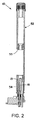
ここで図面を詳細に参照すると、まず初めは図1から図3で、液体クロマトグラフまたは他の分析システムなどの液体取り扱いシステムで使用されるシリンジを洗浄するための例示のシリンジ洗浄ステーションが、全体的に参照番号10で示される。全体的に参照番号11で示されるシリンジは、バレル13と連通するニードル12を含み、ニードルの遠位開口端を通して流体を分注または吸引するために、バレル13内でプランジャ(図示せず)が移動可能である。本明細書でシリンジと称するときは、シリンジ、ピペット、および他の型式のサンプリングプローブを包含する。
Referring now in detail to the drawings, referring first to FIGS. 1-3, an exemplary syringe cleaning station for cleaning a syringe used in a liquid handling system such as a liquid chromatograph or other analytical system is shown generally. This is indicated by the
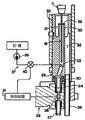
例示されたシリンジ洗浄ステーション10は独立した組立体またはユニットである。さらに図4および図5を参照すると、洗浄ステーション10は全体として、下端部およびシリンジのニードル12を軸方向に挿入可能な開口上端部を有する内部ニードル洗浄室18と、ニードル洗浄室18の開口上端部の上に垂直方向に延在する溢流室21と、洗浄流体を内部室に供給するためにニードル洗浄室の側壁に開口する洗浄ポート22と、ニードル洗浄室18の下端部に連結された排出流路24と、排出流路24を開閉して排出流路を通る流体の流れを、それぞれ許容しおよび阻止する弁26と、を備える。排出流路は、接続金具27に連結された適切な導管によって廃棄物収納容器に連結されてもよい。ソレノイド駆動弁などの任意の適切な弁が使用されてよい。この弁は、適切な接続金具30によって洗浄ステーション本体29に連結された弁組立体28内に収納されてよい。弁の操作は、洗浄ステーション内にユニットとして含まれた、または所望により遠隔配置された、洗浄ステーション制御装置31で制御されてよい。弁は、洗浄ステーション制御装置31で制御されてよいが、手動、または総合的流体取り扱いシステム制御装置などの他の制御デバイスの使用を含む、弁を開閉するための他の手段を設けてもよい。
The illustrated
図に示されているように、ニードル洗浄室18の上端部は内部管状部材30で形成されてよく、内部管状部材30は、その中で洗浄室の残りの部分が形成される洗浄ステーション本体29と一体化して、または分離した部品として形成されてよい。溢流室21は、内部管状部材29と直径がより大きい外部管状部材32との間に形成され、外部管状部材は同様に洗浄ステーション本体と一体化して、または分離した部品として形成されてよい。外部管状部材32は、内部管状部材30を囲むが径方向には離隔して、溢流室の下部を形成する。溢流室の上部は、洗浄室の上端部またはリム33の上に延在し、洗浄室の頂部を通して流出する流体を収集する。溢流室の下端部は排出流路35に連結されており、それは排出管36の下端部に取り付けられた適切な導管で廃棄物収集容器に連結されてよい。
As shown in the figure, the upper end of the
使用に当っては、洗浄流体は、洗浄室18に導入するために、供給源37から洗浄ポート22に供給されてよい。洗浄流体を制御して洗浄室へ分配するために、流体供給源37は制御装置で制御されてよく、またはそのような流体供給源は、いくつかの適用に対しては手動などの他の方法で制御されてもよい。流体供給源は、供給する洗浄流体を貯留するための貯槽38、およびポンプ39、および/または、例えば洗浄ステーション制御装置の制御下で、洗浄流体を洗浄ポートへ圧送供給するように操作可能な、供給弁40を含むことができる。
In use, cleaning fluid may be supplied to the cleaning
弁25が閉のとき(図5で90°回転されたとき)、洗浄ポート22からニードル洗浄室18へ流入する流体は、ニードル洗浄室を満たし、ニードル洗浄室の上端部から溢流して、溢流室21に収集される。溢流室内の流体は、廃棄するために排出流路35を通して排出される。図5に示すように弁が開のときは、洗浄流体は、廃棄するためにニードル洗浄室から洗浄室排出流路24を通して流すことができる。
When the valve 25 is closed (when rotated by 90 ° in FIG. 5), the fluid flowing into the
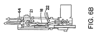
ここで図43および図5と関連して、図6Aから図6Eを参照して洗浄の一例をここに説明する。まず、廃棄するために洗浄室18内が完全に排出されていなかった場合は、そうするために洗浄室排出弁26が開けられる。シリンジ11はデバイス10内に配置され、ニードル12は洗浄室18を囲む壁内に静置されるが、壁には接触しないようにされる。シリンジプランジャ44は図6Aに示すように、シリンジ内に残留している可能性のある任意の内容物を洗浄室に排出するように最下部に移動され、次いでそれらの内容物は洗浄室の排出流路24を通して流出する。
An example of cleaning will now be described with reference to FIGS. 6A to 6E in connection with FIGS. 43 and 5. First, when the interior of the cleaning
次に洗浄室排出弁26は洗浄ステーション制御装置によって閉鎖される。それらの閉鎖は、図6Bおよび図6Cにおいて「X」で図示される。適切な溶媒などの洗浄流体は、洗浄ポート22を通して洗浄室18内に導入される。上述したように、洗浄ポートに流される流体は適切な弁および/またはポンプによって制御され、それらはさらに洗浄ステーション制御装置31によって制御されてよい。代替案または追加案として、手動操作弁の使用などにより流体の供給を手動制御してもよい。
The cleaning
洗浄室18に流入した流体は洗浄室を満たし、廃棄容器に至る経路である溢流室21内に溢流する。この操作で、洗浄室の上端部から下方に延在する、シリンジニードル13の外表面の部分を洗浄する。同時に図6Bに示すように、シリンジプランジャ44を上方に引き抜くことが可能で、それによって清浄な溶媒をニードルの管腔内、およびシリンジ11のバレル46内に吸い込むことができる。
The fluid that has flowed into the cleaning
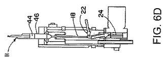
シリンジプランジャ44が指定された最上部位置に達すると、図6Cおよび図6Dに示されるように、洗浄室排出弁26が再び開けられ洗浄室内容物が完全に排出される。このステップでは、所望により溶媒は洗浄室に流入し続けてもよいし、止めてもよい。
When the
図6Eに図示するように、次にシリンジプランジャ44は再び最下部まで伸長され、汚染した溶媒を洗浄室18の下部に排出し、その後それは洗浄室排出流路24を通して廃棄容器へ流れる。
As shown in FIG. 6E, the
図6Bから図6Eまでに例示された上述のステップは、シリンジニードルの内側および外側表面ならびにシリンジバレルに所望の清浄度を達成するように、必要な回数の吸引と分注のストロークを繰り返すことができる。 The above steps illustrated in FIGS. 6B-6E may repeat as many suction and dispensing strokes as necessary to achieve the desired cleanliness on the inner and outer surfaces of the syringe needle and the syringe barrel. it can.
図6Dおよび図6Eに例示された流体の流下によって、著しい利点が得られる。これによって、効率的かつ「即座に」全ての汚染物を洗浄室およびシリンジから廃棄容器へ排出し、洗浄室を清浄な溶媒で充満して次の吸引ステップのために準備する。この過程は洗浄室の流体について、次の式1で表現されるものと同様の、汚染レベルの「ステップ」変化をもたらす。 The fluid flow illustrated in FIGS. 6D and 6E provides significant advantages. This effectively and “instantly” drains all contaminants from the wash chamber and syringe to a waste container, filling the wash chamber with clean solvent and preparing for the next aspiration step. This process results in a “step” change in contamination level for the washroom fluid, similar to that expressed in Equation 1 below.

ここで、Co=汚れたシリンジから分注した直後の洗浄室内の汚染物濃度、Ct=時刻=tにおける洗浄室内の汚染物濃度、Rs=流下した後の残留汚染物濃度、これは主に以前に壁に吸着された検体の脱離に起因する。t=時間、およびto=流出弁が開かれた時刻である。 Here, Co = contaminant concentration in the cleaning chamber immediately after dispensing from a dirty syringe, Ct = contaminant concentration in the cleaning chamber at time = t, Rs = concentration of residual contaminants after flowing down, This is due to the desorption of the specimen adsorbed on the wall. t = time and to = time when the outflow valve is opened.
したがって、高速で、溶媒集約性が少なく、かつ流体を汚染状態から清浄状態へ変えるための効率的手段が提供される。
これとは対照的に、流体が洗浄室から流出されない場合は、流体中に含まれる汚染物は、溶媒が洗浄室から溢流室に流れるときに、式2に示すような、洗浄室に関する指数関数的な汚染の減少を生じる希釈機構によって除去される(清浄な溶媒がポンプで供給されたときの、洗浄室における流体の一時的な均一性を仮定している)。
Thus, an efficient means for changing the fluid from a contaminated state to a clean state is provided that is fast, less solvent intensive and fluid.
In contrast, if the fluid does not flow out of the cleaning chamber, the contaminants contained in the fluid will be an index for the cleaning chamber as shown in
ここで、Co=汚れたシリンジから分注した直後の洗浄室内の汚染物濃度、Ct=時刻=tにおける洗浄室内の汚染物濃度、Rs=流下した後の残留汚染物濃度、これは主に以前に壁に吸着された検体の脱離に起因する。t=時間、to=流出弁が開かれた時刻、SRF=溶媒の流量、およびCV=洗浄室の容積である。 Here, Co = contaminant concentration in the cleaning chamber immediately after dispensing from a dirty syringe, Ct = contaminant concentration in the cleaning chamber at time = t, Rs = concentration of residual contaminants after flowing down, This is due to the desorption of the specimen adsorbed on the wall. t = time, to = time when the spill valve was opened, SRF = solvent flow rate, and CV = cleaning chamber volume.
汚染物は、シリンジの分注ステップとその次の吸引ステップとの間に割り当てられた、任意の妥当な時間内に洗浄室から部分的に除去されるだけである。シリンジは引き続いて吸引ステップの間に、ある程度汚染された溶媒をその中に吸引する。このケースでは、汚染から清浄への変化率は、流入する清浄な溶媒の流量と洗浄室の体積の両方によって決定され、洗浄室の体積が指数関数の「時定数」となる。切り替えの程度(すなわち、洗浄室内の溶媒の最終的な清浄度)は、シリンダ内の初期汚染濃度と、与えられたシリンダの体積および溶媒の流量に対するシリンジの分注と吸引の間に割り当てられた時間と、に依存する。各分注/吸引サイクルに対しておよそ6桁のオーダの希釈を得るためには、シリンダを通して概略14シリンダの体積(時定数)をポンプで流す必要がある。実際には、上述の流体流下手法と同等の清浄度に達するには、この手法は複数倍の溶媒体積が必要であり、相当長い時間が必要である。明らかに、時間、溶媒保存、および全体的効率からみて、シリンジ洗浄デバイスに用いる方法として、溶媒流下方法は希釈方法よりも好ましい。しかし、何らかの理由により希釈法が所望される場合は、この洗浄ステーションは希釈手順を代替として実行するように使用できる。 Contaminants are only partially removed from the wash chamber within any reasonable time assigned between the syringe dispensing step and the subsequent suction step. The syringe subsequently draws some contaminated solvent into it during the suction step. In this case, the rate of change from contamination to clean is determined by both the incoming clean solvent flow rate and the volume of the cleaning chamber, which is the exponential “time constant”. The degree of switching (ie, the final cleanliness of the solvent in the wash chamber) was assigned between the initial contamination concentration in the cylinder and the syringe dispensing and aspiration for a given cylinder volume and solvent flow rate. Depends on time. Approximately 14 cylinder volumes (time constant) need to be pumped through the cylinders to obtain a dilution on the order of approximately 6 orders of magnitude for each dispense / aspiration cycle. In practice, to reach a cleanliness equivalent to the fluid flow technique described above, this technique requires multiple volumes of solvent and requires a much longer time. Obviously, in view of time, solvent storage, and overall efficiency, the solvent flow method is preferred over the dilution method as a method for use in a syringe cleaning device. However, if for some reason a dilution method is desired, the wash station can be used to perform a dilution procedure as an alternative.
層流条件では、汚染された溶媒を洗浄室から除去する時間は、排出流路の有効内半径、排出流路の長さ、排出する液体の粘性、および排出流路の両端間の圧力降下に依存する。圧力降下は重力に依存して実現されるので、排出時間を最短にするには、排出流路の有効内半径を洗浄室の内半径に概ね合わせることができ、排出流路を短く維持できることが必要である。これが現実的でない場合は、排出流路の出口端に吸引ポンプを設置して、それによって洗浄室内から廃棄物収納容器までの圧力降下を増大することにより、所望の排出率を達成できる。 In laminar flow conditions, the time to remove the contaminated solvent from the cleaning chamber depends on the effective inner radius of the discharge channel, the length of the discharge channel, the viscosity of the liquid to be discharged, and the pressure drop across the discharge channel. Dependent. Since the pressure drop is realized depending on gravity, in order to minimize the discharge time, the effective inner radius of the discharge channel can be generally matched with the inner radius of the cleaning chamber, and the discharge channel can be kept short. is necessary. If this is not practical, a desired discharge rate can be achieved by installing a suction pump at the outlet end of the discharge flow path, thereby increasing the pressure drop from the cleaning chamber to the waste container.
図5に示すように、洗浄室排出流路24は、洗浄ポートの下部でニードル洗浄室18に開口しており、洗浄ポートは、ニードル洗浄室の上部リム33の下方でニードル洗浄室の側壁に開口している。洗浄ポートは、図示するように洗浄室の底部付近に、したがってシリンジニードルが洗浄室に挿入され保持されたとき、シリンジニードルの下端より低い位置に配置してよい。洗浄ポートは、代替案および/または追加案として、洗浄室の中央部、または洗浄室の頂部付近または頂部、または洗浄室のリム上部でさえ配置してよい。
As shown in FIG. 5, the cleaning
ニードル洗浄室18はまた、ニードルの周囲に環状空間を画成するように、ニードル13の直径よりも大きい直径を有する。洗浄室の直径は、例えば、ニードルの直径の少なくとも2、3倍またはそれを超えてよい。
The needle wash
図2および図3を再び参照すると、ニードル洗浄室18に挿入されるニードル13を有するシリンジ11を保持するために、洗浄ステーションはさらにホルダ52を備える。例示されたホルダは塔型であり、洗浄室18および溢流室21を含む塔の底部に配置された洗浄ステーション本体29を有する。図示されているように、洗浄室本体は、塔の下端部で管状またはブロック状の部分54内にしっかり保持され、それは次いで弁筐体28に連結される。塔52の堅板部分54は、洗浄室本体29と塔の上端部との間で、中間ガイドおよび支持部材55を支持してもよい。
Referring again to FIGS. 2 and 3, the cleaning station further comprises a
図3に示すようにシリンジ11の上端部は、掴み具、ガントリ機構、またはそれと同様の機構(図示せず)によって把持されるように塔の上端部から突出してよく、それはシリンジをホルダ内へまたはホルダ外へ移動するために使用されてもよい。別のシステムでは、シリンジは手動または他の方法で、洗浄ステーションに挿入され、取り外される。シリンジは、上述のように注入ニードルが洗浄室18内に位置するまで、ロボット的デバイスまたは他の機器を用いて軸方向にシリンジホルダ52内に挿入されてよい。シリンジには、過挿入を防止するためにそのような挿入運動を制限する適切な停止具を設けてよい。
As shown in FIG. 3, the upper end of the syringe 11 may protrude from the upper end of the tower so as to be gripped by a gripper, gantry mechanism, or similar mechanism (not shown), which places the syringe into the holder. Or it may be used to move out of the holder. In other systems, the syringe is inserted or removed from the wash station manually or otherwise. The syringe may be inserted axially into the
ホルダ52は、シリンジ洗浄デバイス10とシリンジ11との通信を確立するためにシリンジのインターフェイスデバイス58を含んでよく、それによって、シリンジからの命令は洗浄ステーション制御装置および/または全体システム制御装置によって受信でき、またはそれらから命令をシリンジに発信できる。このような形で、プランジャを動かすシリンジ内のモータまたは他の動的デバイスは、制御装置31によって制御される。勿論、プランジャを伸長し、および引き込むために、シリンジの端部から延在し、プランジャを動作させるように手動で操作されるプランジャ延長部のような手動手段を含む、他の手段を用いることもできる。
The
図示した例示的実施形態では、インターフェイスデバイス58はシリンジ11と通信し、および/またはシリンジに動力を供給する。インターフェイスデバイス58、およびシリンジ11の対応する接続モジュールのさらなる詳細、ならびに、それら相互のインターフェイスの態様、およびそれらと、ここに説明する洗浄ステーションのような分析システム(単数または複数)の制御構成要素および機能ステーションとのインターフェイスの態様についてのさらなる詳細に関しては、国際特許出願PCT/US06/02845を参照することが可能であり、それは引用することにより本明細書に組み込まれるものとする。具体的な実施例として、洗浄手順は、適切にプログラムされた論理制御デバイスを含む、シリンジ11の制御下で実行されてよい。インターフェイスデバイス58は、洗浄ステーション10内に保持されたとき、動力をシリンジ11に供給してもよい。しかし、従来の液体およびサンプル取り扱いシステムにおいて使用されるシリンジと同様の手動で挿入されるシリンジも含む、別の型式のシリンジを洗浄ステーションのデバイスとして使用することも可能であり、シリンジはガントリシステムまたは別途構成のシステムに係留されてもよいことが、留意される。
In the illustrated exemplary embodiment,
シリンジ11は、ホルダ内でのシリンジの縦方向および/または回転方向の適切な指定位置に関する位置決めキーとして働く、ピンなどの位置決めデバイス60を備えることもできる。位置決めピンは、ホルダ頂部の位置決めスロット内に配置することが可能である。位置決めキーは、シリンジがホルダ52内に軸方向(縦方向)に挿入される範囲を制限するために使用され、または挿入範囲を制限するために別の手段を採用することもできる。
The syringe 11 may also comprise a
上述のように、シリンジ11は洗浄流体を吸引および/または分注するように操作されることが可能である。シリンジは自立式にして係留装置の必要性を解消することも可能であり、それによって、システムを介してサンプリングシリンジの移動を調整する、複雑な操作が低減される。係留されない自立式サンプリングシリンジは通常、プランジャと、命令信号に応答してプランジャを動かすための動的デバイスと、を含む。命令信号は、サンプリングシリンジと定置システムの構成要素との間で、無線により、および/または他の適切な手段によって与えられる。 As described above, the syringe 11 can be operated to aspirate and / or dispense cleaning fluid. The syringe can be self-supporting to eliminate the need for a mooring device, thereby reducing the complex operation of adjusting the movement of the sampling syringe through the system. A non-tethered free-standing sampling syringe typically includes a plunger and a dynamic device for moving the plunger in response to a command signal. The command signal is provided between the sampling syringe and the components of the stationary system, wirelessly and / or by other suitable means.
シリンジ11は長手方向の大部分に渡って円筒状であってよい。シリンジの最大外直径は9mm以下であり、したがってサンプリングシリンジは、操作時に動的に中心間距離9mmまたはそれ未満の格子状に互い同士集合し、または個別に隣り合って配置されることができる。以下で理解されるように、複数のシリンジで並列作業するために、複数の洗浄ステーションを配列できる。具体的には、複数の洗浄ステーション10を互いに隣り合う関係の配列または格子に構成することができる。
The syringe 11 may be cylindrical over most of the longitudinal direction. The maximum outer diameter of the syringe is 9 mm or less, so the sampling syringes can be dynamically assembled to each other in a grid with a center-to-center distance of 9 mm or less during operation, or can be placed individually next to each other. As will be appreciated below, multiple wash stations can be arranged to work in parallel with multiple syringes. Specifically, the plurality of cleaning
上述の説明を考慮すると、本発明は具体的には独立型シリンジ洗浄ステーションであって、実験室での操作に使用されるシリンジを対象として、迅速な、好ましくはハンズフリーな、流体作業を実現する洗浄ステーションを提供することが今や明らかであろう。本発明の原理は、具体的には本明細書に記載されたシリンジを含む、様々な異なる型式のシリンジに適用可能である。 In view of the above description, the present invention is specifically a stand-alone syringe cleaning station that provides rapid, preferably hands-free, fluid work for syringes used in laboratory operations. It will now be apparent to provide a cleaning station. The principles of the present invention are applicable to a variety of different types of syringes, specifically including the syringes described herein.
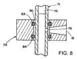
ここで図7と図8を参照すると、別の実施形態の独立型シリンジ洗浄ステーションが、参照番号70によって全体的に示される。洗浄ステーション70は、バレル73と連通するニードル72を含むシリンジ71に使用することが意図されており、シリンジ内で、プランジャ74はニードルの遠位開口端を通して流体を分注または吸引するように移動可能であり、サイドポート76は、具体的にはバレルの上部で、バレル73と連通している。上述したシリンジ11についての説明はシリンジ71に対しても同様に適用可能である。上述の例示の方法ではサイドポートを利用しないのでこれまで説明をしなかったが、シリンジ11もサイドポート76を備えてよい。しかし、サイドポートを備えると、シリンジ11、シリンジ71、および他のシリンジは、本発明に従って洗浄ステーションデバイス70または同様のデバイスで洗浄されることが可能となる。
With reference now to FIGS. 7 and 8, another embodiment of a stand-alone syringe cleaning station is indicated generally by the reference numeral 70. The wash station 70 is intended for use with a
シリンジ洗浄ステーション70は、軸方向に延在しその中にシリンジを軸方向に挿入可能な内部室80を含む本体79と、内部室に洗浄流体を供給するために、内部室に具体的には内部室の側壁に開口している洗浄ポート81とを、備える。軸方向に離隔された1対の環状シール83および84は、図示するようにOリングシールであってよく、シリンジのサイドポート76の両側で、好ましくは円筒状のシリンジ71の外表面を封止するように、洗浄ポート81の両側に位置している。
Syringe cleaning station 70 includes a
洗浄操作の間、シリンジ71を定位置に保持するために、上述したものと同様の適切なホルダ86が設けられてよい。図示するように、ホルダ86は流体容器88から上向きに延在する竪板87を含んでよく、流体容器は竪板の下端部で竪板によって支持され、またはその逆に竪板を支持してよい。竪板87は流体容器の上方で本体79を支持し、シリンジがホルダ87中に完全に挿入され、流体容器内で、ニードルの外側、特にニードルの下部を洗浄するために、ニードルが容器内に入っている洗浄流体に浸されるように、ニードルが流体容器に対して適切に位置決めされたとき、本体はシリンジのサイドポート74と位置を合わせるようにする。ホルダはさらに、シリンジを挿入するときに案内し、ホルダ内でシリンジを支持するために、シリンジガイドおよび支持部材90をホルダに備えてよい。ガイドおよび支持部材は、シリンジが安定した形で保持されるように、本体79の上部に所望の距離に離隔されてよく、また他の手段を採用してもよい。
An
洗浄ポート81への流体の供給、ならびに容器88へのおよびそれからの流体の供給は、上述の説明と同様の態様で行われ得る。すなわち、洗浄ポート81への流体の流れは適切な弁および/またはポンプで制御されてよく、それらはさらに、洗浄ステーション制御装置などの適切な制御装置で制御されてよい。代替案または追加案として、流体の供給は、手動弁などを用いて手動制御されてもよい。さらに流体は、洗浄ステーション制御装置などの制御装置によって制御される適切な弁および/またはポンプなどによって、容器88に供給されることが可能であり、流体は、上述したような排出流路を開閉する弁が設けられた排出流路を介して、容器88から排出されることが可能である。容器を満たしてニードルの外側面を洗浄するために、排出流路を閉鎖することもできる。所望に応じて、容器を上述の洗浄室および溢流室と同様に構成することもできる。 The supply of fluid to the wash port 81 and the supply of fluid to and from the container 88 can be done in a manner similar to that described above. That is, the fluid flow to the wash port 81 may be controlled with appropriate valves and / or pumps, which may be further controlled with a suitable controller, such as a wash station controller. Alternatively or additionally, the fluid supply may be manually controlled using a manual valve or the like. Furthermore, the fluid can be supplied to the container 88 by suitable valves and / or pumps, etc., controlled by a control device such as a cleaning station control device, and the fluid opens and closes the discharge channel as described above. It is possible to discharge from the container 88 through a discharge flow path provided with a valve. The discharge channel can also be closed to fill the container and clean the outer surface of the needle. If desired, the container can be configured similarly to the cleaning chamber and overflow chamber described above.
洗浄ステーション70を使用してシリンジ71を洗浄する例示の方法は、1対の環状シール83および84で仕切られた領域内に位置するサイドポート71を有するシリンジを、洗浄ステーションの軸方向に延在する内部室83内に、軸方向に挿入するステップを含む。次いでプランジャは、ニードル72の遠位開口端から離れたサイドポートの側に位置するように、引き抜かれる。次いで洗浄流体が供給源から洗浄ポートに供給され、内部室に流入する。この流体はそこからサイドポートを通ってシリンジのバレルに流入し、ニードルの遠位端から流出して、それによってシリンジの内側面を洗浄する。
An exemplary method of cleaning the
このように洗浄ステーション70は、迅速で、好ましくはハンズフリーで結合および取り外しを行う流体作業を実現して、実験室での操作に使用されたシリンジを「高速洗浄(“fast−wash”)」する。2つの環状流体シール83および84は、シリンジ本体周りにそれぞれ頂部および底部シールを形成する。シリンジ本体はそれ自体で洗浄キャビティの内側壁を形成し、一方、環状流体シールを支持する構造物は外側洗浄壁として働く。遠隔ポンピング機構から、外側洗浄壁を通り、シリンジのサイドポートを通って、バレル内に入り、シリンジプローブの開口端を通って出るように延在する、開かれた流路が確立される。 In this way, the wash station 70 provides a fluid work that is fast and preferably hands free to couple and remove to “fast-wash” the syringe used for laboratory operation. To do. Two annular fluid seals 83 and 84 form a top and bottom seal, respectively, around the syringe body. The syringe body itself forms the inner wall of the wash cavity, while the structure that supports the annular fluid seal serves as the outer wash wall. From the remote pumping mechanism, an open flow path is established that extends through the outer wash wall, through the side port of the syringe, into the barrel and out through the open end of the syringe probe.
上述の説明で理解されるように、シリンジ71はそれに連結される専用の洗浄配管を必要とせず、したがって従来の設計におけるもつれまたは漏れを解消する。本システムは洗浄ステーション内でシリンジの方位角方向に回転等方性である。洗浄ステーションは、小型のモジュラ型とされることが可能であり、実験室ベンチまたはそれを使用しやすい任意の場所のみでなく、ロボット的デバイスに容易に設置できる。いくつかの洗浄ステーションを取りまとめて、各シリンジの洗浄段階は異なるが、どのようなときにも少なくとも1つの清浄なデバイスを常に提供する、シリンジの貯蔵場所を作ることが可能である。
As will be appreciated in the above description, the
上述の洗浄ステーション10および70の特徴を組み合わせて、サイドポートを有するシリンジまたは有さないシリンジを取り扱える、単一の統合的洗浄ステーションを実現することも可能である。図9に例示するように、洗浄ステーション70の本体79は、洗浄室18の上方で、塔52の竪板部分54に取り付けることができる。したがって、サイドポートを備えるシリンジの内部は、洗浄ステーション70に関連して上述した手順と同様の手順を用いて洗浄することができ、または代替案もしくは追加案として、このシリンジの内部は洗浄ステーション10に関連して上述した態様と同様の態様で洗浄することができる。シリンジがサイドポートを備えない場合は、そのシリンジは洗浄ステーション10に関連して上述した態様と同様の態様で洗浄することができる。全ての場合において、シリンジの外側は洗浄室18を通して流動する洗浄流体によって洗浄できる。
It is also possible to combine the features of the
本発明を、ある特定の1つまたは複数の実施形態に関連して提示し、説明したが、他の当業者が本明細書および添付図面を読み理解することにより、均等な代替と修正を行えることは明らかである。特に上記で説明した要素(構成要素、組立体、デバイス、構成体)によって実行される様々な機能に関して、それらの要素を説明するために使用された語句(「手段(“means”)」の参照を含む)は、別途指示のない限り、たとえ、本明細書で例示された本発明の1つまたは複数の例示的実施形態において機能を遂行する開示された構造と構造的に均等でなくとも、説明された要素の指定された機能を実行する任意の要素(すなわち、機能的に均等な要素)に対応することが意図されている。さらにこれまで、いくつかの例示された実施形態の1つまたは複数に関連して、本発明の特定の特徴を説明したが、所望に応じ、および所与のまたは特定の応用に対して有利であり得るとき、それらの特徴は他の実施形態の1つまたは複数の特徴と組み合わせることも可能である。 Although the present invention has been presented and described in connection with certain specific embodiment (s), other equivalents and modifications can be made by others skilled in the art upon reading and understanding this specification and the accompanying drawings. It is clear. In particular, with respect to the various functions performed by the elements described above (components, assemblies, devices, components), reference to the phrase ("means") used to describe those elements Unless otherwise indicated, even if not structurally equivalent to the disclosed structure performing functions in one or more exemplary embodiments of the invention illustrated herein, unless otherwise indicated. It is intended to correspond to any element that performs a specified function of the described element (ie, a functionally equivalent element). Furthermore, while specific features of the invention have been described above in connection with one or more of several illustrated embodiments, they may be advantageous as desired and for a given or specific application. Where possible, those features can be combined with one or more features of other embodiments.
Claims (16)
下端部、および前記シリンジの前記ニードルが軸方向に挿入可能な開口上端部、を有する内部ニードル洗浄室と、
前記ニードル洗浄室の前記開口上端部の上に垂直方向に延在する溢流室と、
洗浄流体を前記内部室に供給するために前記ニードル洗浄室の側壁に開口する洗浄ポートと、
前記ニードル洗浄室の前記下端部に連結された排出流路と、
前記排出流路を開閉して前記排出流路を通る流体の流れを、それぞれ許容しおよび阻止するための弁であって、前記弁が閉のときは、前記洗浄ポートから前記ニードル室に流入する流体が前記ニードル洗浄室を満たし、前記ニードル洗浄室の前記上端部を溢流して前記溢流室へ流れることができ、前記弁が開のときは、洗浄流体が前記ニードル洗浄室から前記排出流路を通って流れることができる弁と、
を備えるシリンジ洗浄ステーション。 Including said needle in communication with a barrel within which a plunger is movable to dispense or aspirate fluid through the distal open end of the needle, used in a liquid handling system or used to perform a liquid handling operation A syringe cleaning station for cleaning the syringe,
An inner needle cleaning chamber having a lower end, and an upper end of the opening into which the needle of the syringe can be inserted in the axial direction;
An overflow chamber extending vertically above the upper end of the opening of the needle cleaning chamber;
A cleaning port that opens to the side wall of the needle cleaning chamber to supply cleaning fluid to the internal chamber;
A discharge channel connected to the lower end of the needle cleaning chamber;
A valve for opening and closing the discharge flow path to allow and block the flow of fluid through the discharge flow path, respectively, and flows into the needle chamber from the washing port when the valve is closed When the fluid fills the needle cleaning chamber, overflows the upper end of the needle cleaning chamber and flows to the overflow chamber, and when the valve is open, the cleaning fluid flows from the needle cleaning chamber to the discharge flow. A valve that can flow through the road,
A syringe cleaning station comprising:
前記シリンジのサイドポートの両側で、前記シリンジの外面を封止するために、軸方向に離隔され、前記洗浄ポートの対向する側に配置された1対の環状シールと、
をさらに備える、請求項1から7のいずれか1項に記載のシリンジ洗浄ステーション。 A body that extends in the axial direction and defines an internal chamber into which the syringe can be inserted in the axial direction, and a cleaning port that opens in a side wall of the internal chamber to supply cleaning fluid to the internal chamber When,
A pair of annular seals spaced axially and disposed on opposite sides of the wash port to seal the outer surface of the syringe on both sides of the side port of the syringe;
The syringe cleaning station according to any one of claims 1 to 7, further comprising:
(a)洗浄ステーションにおいて、軸方向に延在するニードル洗浄室の開口上端部を通して、前記シリンジを軸方向に挿入するステップと、
(b)前記ニードル洗浄室の上端部および下端部の間の、前記ニードル洗浄室の側壁にある洗浄ポート開口部を通して洗浄流体を流すステップと、
(c)洗浄流体を前記ニードル洗浄室に満たし、前記ニードル洗浄室の上部開口端を通して溢流室内に流出させるように、前記排出流路を閉鎖するステップと、
(d)前記ニードル洗浄室内の前記洗浄流体が排出流路を通して流出するように、前記排出流路を開くステップと、
(e)ステップ(c)の間に、洗浄流体を前記ニードルを通して前記シリンジの前記バレル内に吸い込むように、前記シリンジの前記プランジャを引き込むステップと、
(f)ステップ(d)の間に、前記洗浄流体を、前記シリンジの前記バレルから前記ニードルを通して、前記ニードル洗浄室から前記排出流路へ流れる前記流体中に排出するように、前記シリンジの前記プランジャを伸長するステップと、
を含む方法。 Including said needle in communication with a barrel within which a plunger is movable to dispense or aspirate fluid through the distal open end of the needle, used in a liquid handling system or used to perform a liquid handling operation A method of washing the syringe, comprising:
(A) in the cleaning station, inserting the syringe in the axial direction through the upper opening of the needle cleaning chamber extending in the axial direction;
(B) flowing a cleaning fluid through a cleaning port opening in a side wall of the needle cleaning chamber between an upper end and a lower end of the needle cleaning chamber;
(C) filling the needle cleaning chamber with the cleaning fluid and closing the discharge flow path so as to flow into the overflow chamber through the upper opening end of the needle cleaning chamber;
(D) opening the discharge channel so that the cleaning fluid in the needle cleaning chamber flows out through the discharge channel;
(E) retracting the plunger of the syringe to draw wash fluid through the needle and into the barrel of the syringe during step (c);
(F) During step (d), the cleaning fluid is discharged from the barrel of the syringe through the needle into the fluid flowing from the needle cleaning chamber to the discharge flow path. Extending the plunger; and
Including methods.
軸方向に延在し、内部に前記シリンジを軸方向に挿入することができる内部室、および
洗浄流体を前記内部室に供給するために前記内部室の側壁に開口する洗浄ポート、を画成する本体と、
前記シリンジのサイドポートの両側で、前記シリンジの外面を封止するために、軸方向に離隔され、前記洗浄ポートの対向する側に配置された1対の環状シールと、
を備えるシリンジ洗浄ステーション。 The needle in communication with a barrel within which a plunger is movable to dispense or aspirate fluid through the distal open end of the needle, and a side port in communication with the barrel, used in a liquid handling system, or A syringe cleaning station for cleaning a syringe used to perform a liquid handling operation,
An axial chamber extending in the axial direction, in which the syringe can be inserted axially, and a cleaning port opening in a side wall of the internal chamber for supplying cleaning fluid to the internal chamber are defined. The body,
A pair of annular seals spaced axially and disposed on opposite sides of the wash port to seal the outer surface of the syringe on both sides of the side port of the syringe;
A syringe cleaning station comprising:
前記洗浄ポートの両側で前記シリンジの外面を封止するために軸方向に離隔され前記洗浄ポートの両側に配置された、1対の環状シールで仕切られた領域内に前記サイドポートが位置するように、前記シリンジを洗浄ステーションの軸方向に延在する内部室内に軸方向に挿入するステップと、
前記プランジャが前記ニードルの前記遠位端から離れた前記サイドポートの側に位置するように、前記シリンジの前記プランジャを引き抜くステップと、
前記サイドポートを通って前記シリンジの前記バレルに流入し、前記ニードルの前記遠位端から流出して、それによって前記シリンジの内側面を洗浄する洗浄流体を、前記洗浄ポートを通して前記内部室に流入させるステップと、
を含む方法。 The needle in communication with a barrel within which a plunger is movable to dispense or aspirate fluid through the distal open end of the needle, and a side port in communication with the barrel, used in a liquid handling system, or A method of cleaning a syringe used to perform a liquid handling operation,
The side port is located in a region separated by a pair of annular seals that are axially spaced apart and arranged on both sides of the washing port to seal the outer surface of the syringe on both sides of the washing port. And inserting the syringe axially into an interior chamber extending in the axial direction of the cleaning station;
Withdrawing the plunger of the syringe so that the plunger is located on the side port side away from the distal end of the needle;
A cleaning fluid that flows into the barrel of the syringe through the side port and out of the distal end of the needle, thereby cleaning the inner surface of the syringe, flows into the internal chamber through the cleaning port. Step to
Including methods.
Applications Claiming Priority (3)
| Application Number | Priority Date | Filing Date | Title |
|---|---|---|---|
| US74839805P | 2005-12-08 | 2005-12-08 | |
| US82114706P | 2006-08-02 | 2006-08-02 | |
| PCT/US2006/061804 WO2007117321A2 (en) | 2005-12-08 | 2006-12-08 | Syringe wash station for analytical applications |
Publications (1)
| Publication Number | Publication Date |
|---|---|
| JP2009518655A true JP2009518655A (en) | 2009-05-07 |
Family
ID=38535277
Family Applications (1)
| Application Number | Title | Priority Date | Filing Date |
|---|---|---|---|
| JP2008544664A Pending JP2009518655A (en) | 2005-12-08 | 2006-12-08 | Syringe wash station for analytical applications |
Country Status (4)
| Country | Link |
|---|---|
| US (1) | US20090032065A1 (en) |
| EP (1) | EP1963868A2 (en) |
| JP (1) | JP2009518655A (en) |
| WO (1) | WO2007117321A2 (en) |
Families Citing this family (8)
| Publication number | Priority date | Publication date | Assignee | Title |
|---|---|---|---|---|
| US9103782B2 (en) | 2008-12-02 | 2015-08-11 | Malvern Instruments Incorporated | Automatic isothermal titration microcalorimeter apparatus and method of use |
| FR2946056B1 (en) * | 2009-06-02 | 2011-07-22 | Interlab | DEVICE AND METHOD FOR CLEANING A PEN EQUIPPED WITH AN AUTOMATE FOR SOWING A CULTURE SUBSTRATE. |
| CN103521480B (en) * | 2012-07-06 | 2016-10-26 | 深圳市麦迪聪医疗电子有限公司 | A kind of cleaning method of the automatic clearing apparatus of sampling needle |
| WO2018017752A1 (en) * | 2016-07-21 | 2018-01-25 | Siemens Healthcare Diagnostics Inc. | Basin and high speed air solution |
| US11327055B2 (en) * | 2018-03-29 | 2022-05-10 | Waters Technologies Corporation | Autosampler seal pack for reducing a carryover percentage |
| US10456815B1 (en) * | 2018-10-16 | 2019-10-29 | Bluebonnet Foods, L.P. | Injector needle cleaning apparatus and method |
| CN115956206A (en) * | 2020-08-17 | 2023-04-11 | 沃特世科技公司 | Dual delivery needle washing system |
| CN114700353B (en) * | 2022-03-14 | 2022-12-23 | 首都医科大学 | Preventive medicine waste treatment device |
Citations (3)
| Publication number | Priority date | Publication date | Assignee | Title |
|---|---|---|---|---|
| JPS6212986B2 (en) * | 1984-05-15 | 1987-03-23 | Tokyo Daigaku | |
| JPH04105066A (en) * | 1990-08-24 | 1992-04-07 | Olympus Optical Co Ltd | Probe washing vessel |
| JPH0894641A (en) * | 1994-09-28 | 1996-04-12 | Yasunobu Tsukioka | Cleaning device for dispensing nozzle in inspection apparatus of blood and the like |
Family Cites Families (99)
| Publication number | Priority date | Publication date | Assignee | Title |
|---|---|---|---|---|
| US2269648A (en) * | 1937-10-25 | 1942-01-13 | Samuel F Cole | Viscometer |
| US3401692A (en) * | 1964-06-26 | 1968-09-17 | Micro Tek Instr Corp | Syringe provided with a lateral vent and having high compression seals within the syringe bore |
| US3279659A (en) * | 1965-03-02 | 1966-10-18 | Prec Sampling Corp | Injection apparatus |
| US3489525A (en) * | 1967-08-25 | 1970-01-13 | Scientific Industries | System of automatic analysis |
| US3738493A (en) * | 1971-09-24 | 1973-06-12 | Analytical Instr Spec | Apparatus for simultaneous application of samples to thin layer chromatography plates |
| GB1401858A (en) * | 1972-08-09 | 1975-07-30 | Rank Organisation Ltd | Analytical apparatus |
| US3915651A (en) * | 1972-09-22 | 1975-10-28 | Us Government | Direct digital control pipette |
| JPS5630500B2 (en) * | 1974-02-27 | 1981-07-15 | ||
| US3912456A (en) * | 1974-03-04 | 1975-10-14 | Anatronics Corp | Apparatus and method for automatic chemical analysis |
| US3957051A (en) * | 1974-09-13 | 1976-05-18 | Medical Development Corporation | Pump-type syringe having double-acting piston construction |
| US3991616A (en) * | 1975-09-08 | 1976-11-16 | Hans Noll | Automatic pipetter |
| LU77642A1 (en) * | 1976-07-09 | 1977-10-03 | ||
| DE2704239C3 (en) * | 1977-02-02 | 1979-11-29 | Bodenseewerk Perkin-Elmer & Co Gmbh, 7770 Ueberlingen | Device for the repeated taking of measuring samples from liquids |
| US4162030A (en) * | 1977-04-20 | 1979-07-24 | J. Claybrook Lewis and Associates, Ltd. | Disposable package dispenser having a pressure release channel |
| US4094197A (en) * | 1977-07-21 | 1978-06-13 | Harris Sr Rano J | Semi-automatic and automatic fluid injectors |
| US4182184A (en) * | 1978-12-14 | 1980-01-08 | Rheodyne Incorporated | Sample injector |
| US4276048A (en) * | 1979-06-14 | 1981-06-30 | Dynatech Ag | Miniature reaction container and a method and apparatus for introducing micro volumes of liquid to such a container |
| US4217780A (en) * | 1979-07-09 | 1980-08-19 | Ortho Diagnostic, Inc. | Automated, self-cleaning fluid sampling apparatus |
| US4310057A (en) * | 1980-05-30 | 1982-01-12 | Brame Durward B | Apparatus for extracting subterranean gas samples |
| US4346742A (en) * | 1980-06-02 | 1982-08-31 | P.M. America, Inc. | Method for diluting a liquid test sample and computer controlld diluting apparatus |
| US4459864A (en) * | 1981-10-19 | 1984-07-17 | Electro-Nucleonics, Inc. | Fluid loading and dispensing device |
| EP0141148B1 (en) * | 1983-09-14 | 1989-11-23 | CARLO ERBA STRUMENTAZIONE S.p.A. | Automatic sample apparatus and sampling method |
| US4519258A (en) * | 1983-10-11 | 1985-05-28 | Eastman Kodak Company | Motorized pipette |
| US4563907A (en) * | 1983-10-31 | 1986-01-14 | Micromedic Systems Inc. | Direct reading automatic pipette |
| US5187990A (en) * | 1984-02-16 | 1993-02-23 | Rainin Instrument Co., Inc. | Method for dispensing liquids with a pipette with compensation for air pressure and surface tension |
| US4676951A (en) * | 1985-07-01 | 1987-06-30 | American Hospital Supply Corp. | Automatic specimen analyzing system |
| US4681741A (en) * | 1985-07-01 | 1987-07-21 | American Hospital Supply Corporation | Reagent dispenser for an analyzing system |
| US4624148A (en) * | 1985-09-20 | 1986-11-25 | Dynatech Precision Sampling Corporation | Automatic fluid injector |
| US4713974A (en) * | 1986-04-18 | 1987-12-22 | Varian Associates, Inc./Scientific Systems, Inc. | Autosampler |
| US4769009A (en) * | 1986-10-10 | 1988-09-06 | Cobe Laboratories, Inc. | Apparatus for displacing a piston in a chamber having a torque resistor |
| GR871619B (en) * | 1986-10-31 | 1988-03-03 | Genetic Systems Corp | Automated patient sample analysis instrument |
| US4833384A (en) * | 1987-07-20 | 1989-05-23 | Syntex (U.S.A.) Inc. | Syringe drive assembly |
| US5055263A (en) * | 1988-01-14 | 1991-10-08 | Cyberlab, Inc. | Automated pipetting system |
| US4821586A (en) * | 1988-02-25 | 1989-04-18 | Medical Laboratory Automation, Inc. | Programmable pipette |
| DE68928695T2 (en) * | 1989-07-24 | 1998-09-24 | Bayer Ag | SUCTION AND DISPENSING DEVICE FOR LIQUID PATTERN |
| US4984475A (en) * | 1989-07-24 | 1991-01-15 | Tritech Partners | Ultra low carryover sample liquid analysis apparatus and method |
| US5277871A (en) * | 1989-10-20 | 1994-01-11 | Hitachi, Ltd. | Liquid chromatographic analyzer, sample feeder and prelabeling reaction treating method |
| FR2654836B1 (en) * | 1989-11-17 | 1994-01-28 | Biotrol Sa Laboratoires | APPARATUS FOR AUTOMATICALLY PERFORMING MULTIPLE SUCCESSIVE IMMUNODAYS OF AT LEAST ONE BIOLOGICAL SUBSTANCE IN A PLURALITY OF BIOLOGICAL SAMPLES, PROCESS AND REAGENT USING THE SAME. |
| US4989623A (en) * | 1989-12-01 | 1991-02-05 | Akzo N.V. | Apparatus and method for cleaning reagent delivery probes |
| US5183638A (en) * | 1989-12-04 | 1993-02-02 | Kabushiki Kaisha Nittec | Automatic immunity analysis apparatus with magnetic particle separation |
| JPH087222B2 (en) * | 1990-01-18 | 1996-01-29 | 持田製薬株式会社 | Automatic dispensing dilution device |
| US5734424A (en) * | 1990-08-08 | 1998-03-31 | Canon Kabushiki Kaisha | Image pickup apparatus capable of providing moving video signal and still video signal |
| US5176646A (en) * | 1991-02-19 | 1993-01-05 | Takayuki Kuroda | Motorized syringe pump |
| US5238654A (en) * | 1992-06-01 | 1993-08-24 | Spectra-Physics Analytical, Inc. | Syringe drive with lead screw mechanism |
| US5328654A (en) * | 1992-10-05 | 1994-07-12 | The Dow Chemical Company | Orientation of never-dried molecular composite films |
| US5348585A (en) * | 1993-01-07 | 1994-09-20 | Weston Colin K | Liquid dispensing apparatus |
| GB2274064B (en) * | 1993-01-12 | 1996-04-17 | David Lile Reynolds | Intravenous infusion of pharmaceuticals |
| US5522804A (en) * | 1994-02-15 | 1996-06-04 | Lynn; Lawrence A. | Aspiration, mixing, and injection syringe |
| CA2192652A1 (en) * | 1994-07-11 | 1996-01-25 | Prabhakar P. Rao | Modular vial autosampler |
| US5567122A (en) * | 1994-10-13 | 1996-10-22 | Barry J. Walter | Cylinder pump having controllable piston/drive detachment |
| JP3481705B2 (en) * | 1994-12-12 | 2003-12-22 | 株式会社モリテックス | Automatic solid-phase extraction device |
| US5651775A (en) * | 1995-07-12 | 1997-07-29 | Walker; Richard Bradley | Medication delivery and monitoring system and methods |
| WO1997003766A1 (en) * | 1995-07-14 | 1997-02-06 | Pasteur Sanofi Diagnostics | Apparatus and method for washing a pipette probe |
| JP2901521B2 (en) * | 1995-07-31 | 1999-06-07 | アロカ株式会社 | Biological tissue processing equipment |
| DE19610607A1 (en) * | 1996-03-18 | 1997-09-25 | Boehringer Mannheim Gmbh | Device for cleaning pipetting needles or stirrers |
| CA2255839A1 (en) * | 1996-07-05 | 1998-01-15 | Mark Gross | Automated sample processing system |
| US5897837A (en) * | 1997-02-06 | 1999-04-27 | Toa Medical Electronics Co., Ltd. | Dispensing device and Immunoassay apparatus using the same |
| US6045759A (en) * | 1997-08-11 | 2000-04-04 | Ventana Medical Systems | Fluid dispenser |
| US6902703B2 (en) * | 1999-05-03 | 2005-06-07 | Ljl Biosystems, Inc. | Integrated sample-processing system |
| GB9800933D0 (en) * | 1998-01-17 | 1998-03-11 | Central Research Lab Ltd | A dispenser |
| US6241950B1 (en) * | 1998-02-13 | 2001-06-05 | Airxpert Systems, Inc. | Fluid sampling system |
| US6033911A (en) * | 1998-02-27 | 2000-03-07 | Hamilton Company | Automated assaying device |
| US6406632B1 (en) * | 1998-04-03 | 2002-06-18 | Symyx Technologies, Inc. | Rapid characterization of polymers |
| US6519032B1 (en) * | 1998-04-03 | 2003-02-11 | Symyx Technologies, Inc. | Fiber optic apparatus and use thereof in combinatorial material science |
| US6146594A (en) * | 1999-02-10 | 2000-11-14 | Robbins Scientific Corporation | Syringe array with adjustable needle spacing |
| US6551557B1 (en) * | 1998-07-07 | 2003-04-22 | Cartesian Technologies, Inc. | Tip design and random access array for microfluidic transfer |
| DE19835833A1 (en) * | 1998-08-07 | 2000-02-17 | Max Planck Gesellschaft | Dosing head for parallel processing of a large number of fluid samples |
| US6374683B1 (en) * | 1999-01-29 | 2002-04-23 | Genomic Instrumentation Services, Inc. | Pipetter |
| DE19915066C2 (en) * | 1999-04-01 | 2001-09-13 | Brand Gmbh & Co Kg | Method for recognizing the type of exchangeable device-specific piston-cylinder units for pipetting or dosing devices as well as pipetting and dosing systems |
| US7214540B2 (en) * | 1999-04-06 | 2007-05-08 | Uab Research Foundation | Method for screening crystallization conditions in solution crystal growth |
| US7244396B2 (en) * | 1999-04-06 | 2007-07-17 | Uab Research Foundation | Method for preparation of microarrays for screening of crystal growth conditions |
| US6143252A (en) * | 1999-04-12 | 2000-11-07 | The Perkin-Elmer Corporation | Pipetting device with pipette tip for solid phase reactions |
| US7160511B2 (en) * | 2000-02-18 | 2007-01-09 | Olympus Corporation | Liquid pipetting apparatus and micro array manufacturing apparatus |
| AU2001250924A1 (en) * | 2000-03-22 | 2001-10-03 | Docusys, Inc. | A drug delivery and monitoring system |
| US6387330B1 (en) * | 2000-04-12 | 2002-05-14 | George Steven Bova | Method and apparatus for storing and dispensing reagents |
| US6694197B1 (en) * | 2000-04-24 | 2004-02-17 | Pharmacopeia Drug Discovery Inc. | Single channel reformatter |
| US6393898B1 (en) * | 2000-05-25 | 2002-05-28 | Symyx Technologies, Inc. | High throughput viscometer and method of using same |
| DE10041231A1 (en) * | 2000-08-22 | 2002-03-07 | Leica Microsystems | Device for treating objects |
| US6864091B1 (en) * | 2000-08-31 | 2005-03-08 | Symyx Technologies, Inc. | Sampling probe |
| AU2001289472A1 (en) * | 2000-10-06 | 2002-04-15 | Chemspeed Ltd | Device comprising a tool holder and a removably attachable tool |
| US6343717B1 (en) * | 2000-11-21 | 2002-02-05 | Jack Yongfeng Zhang | Pre-filled disposable pipettes |
| US6360794B1 (en) * | 2000-12-19 | 2002-03-26 | Bechtel Bwxt Idaho, Llc | Apparatus and method for delivering a fluid to a container |
| IL156245A0 (en) * | 2000-12-22 | 2004-01-04 | Dca Design Int Ltd | Drive mechanism for an injection device |
| US6802228B2 (en) * | 2001-03-29 | 2004-10-12 | Dong C. Liang | Microsample analysis system using syringe pump and injection port |
| US6812030B2 (en) * | 2001-04-25 | 2004-11-02 | Biotrove, Inc. | System and method for high throughput sample preparation and analysis using column chromatography |
| US20050123970A1 (en) * | 2001-04-25 | 2005-06-09 | Can Ozbal | High throughput autosampler |
| US6526812B2 (en) * | 2001-07-14 | 2003-03-04 | Leap Technologies, Inc. | Self-washing injection apparatus |
| US6846680B2 (en) * | 2001-07-31 | 2005-01-25 | Caliper Life Sciences, Inc. | Liquid handling system with automatically interchangeable cannula array |
| EP1470427B1 (en) * | 2002-01-25 | 2007-11-07 | Innovadyne Technologies, Inc. | Low volume, non-contact liquid dispensing method |
| US6840121B2 (en) * | 2002-07-18 | 2005-01-11 | University Of Florida Reasearch Foundation, Inc. | Self-powered fluid sampler |
| US20040123650A1 (en) * | 2002-09-17 | 2004-07-01 | Symyx Technologies, Inc. | High throughput rheological testing of materials |
| US7284454B2 (en) * | 2004-05-27 | 2007-10-23 | Matrix Technologies Corporation | Hand held pipette |
| US6884231B1 (en) * | 2002-10-17 | 2005-04-26 | Hamilton Company | Dual chambered fluid displacement apparatus |
| JP4016811B2 (en) * | 2002-11-15 | 2007-12-05 | 日立工機株式会社 | Automatic dispensing device |
| US7125727B2 (en) * | 2003-01-29 | 2006-10-24 | Protedyne Corporation | Sample handling tool with piezoelectric actuator |
| US7024955B2 (en) * | 2003-03-01 | 2006-04-11 | Symyx Technologies, Inc. | Methods and systems for dissolution testing |
| KR101100094B1 (en) * | 2003-05-15 | 2011-12-29 | 가부시키가이샤 시세이도 | Specimen filling device, specimen filling method, and liquid chromatography device with the specimen filling device |
| DE102004003434B4 (en) * | 2004-01-21 | 2006-06-08 | Eppendorf Ag | Pipetting device with a displacement device and a drive device detachably connected thereto |
| WO2007024798A2 (en) * | 2005-08-22 | 2007-03-01 | Applera Corporation | Apparatus, system, and method using immiscible-fluid-discrete-volumes |
-
2006
- 2006-12-08 US US12/096,712 patent/US20090032065A1/en not_active Abandoned
- 2006-12-08 EP EP06850255A patent/EP1963868A2/en not_active Withdrawn
- 2006-12-08 WO PCT/US2006/061804 patent/WO2007117321A2/en active Search and Examination
- 2006-12-08 JP JP2008544664A patent/JP2009518655A/en active Pending
Patent Citations (3)
| Publication number | Priority date | Publication date | Assignee | Title |
|---|---|---|---|---|
| JPS6212986B2 (en) * | 1984-05-15 | 1987-03-23 | Tokyo Daigaku | |
| JPH04105066A (en) * | 1990-08-24 | 1992-04-07 | Olympus Optical Co Ltd | Probe washing vessel |
| JPH0894641A (en) * | 1994-09-28 | 1996-04-12 | Yasunobu Tsukioka | Cleaning device for dispensing nozzle in inspection apparatus of blood and the like |
Also Published As
| Publication number | Publication date |
|---|---|
| WO2007117321A2 (en) | 2007-10-18 |
| EP1963868A2 (en) | 2008-09-03 |
| US20090032065A1 (en) | 2009-02-05 |
| WO2007117321A3 (en) | 2008-03-27 |
| WO2007117321B1 (en) | 2008-05-08 |
Similar Documents
| Publication | Publication Date | Title |
|---|---|---|
| JP2009518655A (en) | Syringe wash station for analytical applications | |
| AU666052B2 (en) | Fluid probe washing apparatus and method | |
| EP1766418B1 (en) | Probe washing cups and methods | |
| RU2484470C2 (en) | High-speed sample feeding device | |
| US7198956B2 (en) | Automated fluid handling system and method | |
| EP2245468B1 (en) | Apparatus and method for cleaning a liquid handling probe | |
| JPH07185360A (en) | Automatic pipette sampling device | |
| WO2002016039A1 (en) | Pipet device with disposable tip | |
| EP2145016B1 (en) | Wash ring assembly and method of use | |
| KR101148509B1 (en) | Method and apparatus for liquid chromatography automated sample loading | |
| WO1997003766A1 (en) | Apparatus and method for washing a pipette probe | |
| JP2019514356A (en) | Methods and assemblies for recovering molecules | |
| JPH076997B2 (en) | Sampling device and method | |
| RU2730922C2 (en) | Device and method for high-accuracy sampling of liquids in an automatic sample analyzer | |
| US20050197538A1 (en) | Reagent and sample introduction plunger device for a syringe | |
| US20030213504A1 (en) | Method for rinsing micro-dispensing syringes | |
| JPH03230000A (en) | Pressure reducing absorbing device of liquid | |
| CN114907962A (en) | Sample detection pretreatment equipment and reagent card box therein | |
| CN116256527A (en) | Sample analyzer and ultrasonic cleaning device | |
| AU2932402A (en) | Method for rinsing micro-dispensing syringes |
Legal Events
| Date | Code | Title | Description |
|---|---|---|---|
| A621 | Written request for application examination |
Free format text: JAPANESE INTERMEDIATE CODE: A621 Effective date: 20090826 |
|
| A131 | Notification of reasons for refusal |
Free format text: JAPANESE INTERMEDIATE CODE: A131 Effective date: 20110627 |
|
| A601 | Written request for extension of time |
Free format text: JAPANESE INTERMEDIATE CODE: A601 Effective date: 20110926 |
|
| A602 | Written permission of extension of time |
Free format text: JAPANESE INTERMEDIATE CODE: A602 Effective date: 20111003 |
|
| A02 | Decision of refusal |
Free format text: JAPANESE INTERMEDIATE CODE: A02 Effective date: 20120229 |