EP0141148B1 - Automatic sample apparatus and sampling method - Google Patents
Automatic sample apparatus and sampling method Download PDFInfo
- Publication number
- EP0141148B1 EP0141148B1 EP84110549A EP84110549A EP0141148B1 EP 0141148 B1 EP0141148 B1 EP 0141148B1 EP 84110549 A EP84110549 A EP 84110549A EP 84110549 A EP84110549 A EP 84110549A EP 0141148 B1 EP0141148 B1 EP 0141148B1
- Authority
- EP
- European Patent Office
- Prior art keywords
- needle
- injector
- duct
- switch element
- sample
- Prior art date
- Legal status (The legal status is an assumption and is not a legal conclusion. Google has not performed a legal analysis and makes no representation as to the accuracy of the status listed.)
- Expired
Links
Images


Classifications
-
- G—PHYSICS
- G01—MEASURING; TESTING
- G01N—INVESTIGATING OR ANALYSING MATERIALS BY DETERMINING THEIR CHEMICAL OR PHYSICAL PROPERTIES
- G01N30/00—Investigating or analysing materials by separation into components using adsorption, absorption or similar phenomena or using ion-exchange, e.g. chromatography or field flow fractionation
- G01N30/02—Column chromatography
- G01N30/04—Preparation or injection of sample to be analysed
- G01N30/24—Automatic injection systems
Definitions
- This invention relates to an automatic sampling apparatus for the injection of samples to be analyzed in a gas chromatographic column, and particularly designed to be used in case of sample injections by means of non vaporizing direct on-column injectors, with the use of a new washing and discharging element specially designed for said apparatus.
- the invention also relates to a sampling method to be used with said apparatus.
- Said automatic samplers may comprise samplers wherein an injection syringe is movable from the sample vials to the injector but these samplers show many drawbacks, so that samplers with the injection syringe fixedly aligned with the injector are preferred.
- These last automatic samplers essentially include: an automatic device capable of drawing the sample to be analyzed from a container (a vial) and of feeding it to an injection syringe mounted in line with the inlet part (injection port) of an injector and carrying a needle; automatic means capable of washing the whole sample feeding system in such a way that, at the end of the injection stage of each sample, the device is ready for feeding the syringe with a new sample, without the danger that the syringe is contaminated by traces of the previously injected sample; automatic means actuating the injection syringe and/or needle movements into and out the injector; automatic means for measuring the exact amount of sample to be introduced into the gas chromatographic column; and automatic means for introducing the sample into the gas chromatographic column.
- a switch element is generally foreseen between the injection syringe and the injector.
- the first type does not warrant a perfect alignment between the syringe needle and the on-column injector
- the second type as the first one, requires the use of sample injection syringes equipped with very thin needles, capable of penetrating inside the gas chromatographic capillary column which presents an internal diameter of approximately 0.2-0.3 mm.
- Said peculiarity of on-column injectors represents a considerable problem, in that the aforementioned switch element comprises rubber septa hardly pierceable by extremely thin needles, such as those used in on-column injectors.
- the automatic means actuating the injection syringe needle movements into and out of the injector do not assure a sufficient precision of operation as necessary for safe introduction into the gas chromatographic column of the very thin and extremely flexible needle used with the on-column type injectors.
- the switch element when used in combination with a direct on-column injector, not only drains the washing liquid and exceeding sample, but ensures that the needle outer surface and the switch element surfaces which will contact the needle are completely free from liquid sample traces which could create an injector pollution in such a manner that the results of an analysis on a sample could be negatively influenced by traces of the previously analyzed sample.
- US-A-3604269 discloses a gas chromatography sample injection apparatus for mounting on the top of a chromatographic column and for introduction of a liquid sample into said column by means of a piston-type syringe.
- Said apparatus comprises an automatic device to introduce the sample into the syringe and to introduce a washing liquid into the syringe such as to clean same between samples, as well as means located between the injector and the syringe to drain the washing liquid and excess of liquid sample.
- the syringe and the syringe needle are moved into and out of the injector, and the syringe is operated for injecting a selected amount of liquid sample into the chromatograhpic column.
- EP-A-32560 discloses a non vapourizing direct on-column injector having a control valve allowing an injector washing operation to be carried out by the carrier gas. No drain of liquid sample excess and washing liquid is foreseen and the problem of drying the needle outer surface is not envisaged.
- an object of this invention is to provide an automatic sampling apparatus suitable for injection of samples to be analyzed by injectors of the non vapourizing direct on-column type for capillary columns.
- a further object of the present invention is to provide a sampling apparatus with a switch element which, besides allowing drainage of the washing liquid and of the exceeding sample without letting them penetrate the injector during said operations, also allows to eliminate any trace of liquid from the needle end as well as from external walls of the needle and from the switch element surfaces which can be in contact with the needle, in a way that it is absolutely certain that during the needle introduction into the injector no trace of liquid sample is dragged by the needle itself inside the injector, with injector pollution.
- Another object of this invention is to provide, in a sampling apparatus as above said, a device capable of guiding the needle in its movements, in order to warrant that distortions of the needle do not occur specially due to bending and compressive stress acting on same, so that it is possible to reduce even the diameter of said needle.
- an automatic sampling apparatus for the injection of samples to be analyzed in a gas chromatographic capillary column, comprising an automatic feeding device for alternatively and controlled feeding each sample and a washing fluid to an injection syringe, an injector device having a through passage for a needle fluidically connected with the syringe, a switch element to let the washing fluid and sample excess off, said switch element being placed between said injector device and said syringe and having a duct coaxial with the injector through passage and means for moving the syringe needle within the switch element duct and into and out of the injector, characterized in that said injector device is an injector of the non vapourizing direct on-column type; in that said switch element duct is closed at least at its bottom by a pierceable sealing septum; in that said injection needle has an outer diameter greater than 0.4 mm; in that the diameter of said switch element duct and injector passage for the sample injection syringe needle is greater than or equal to 0.5
- the switch element is pneumatically mounted on the injector body and is constantly fed, during the sample injection step, with carrier or inert gas to dry the needle outer surface.
- the needle is inserted in strictly aligned holes of a series of small arms superimposed and spaced between each other; starting from the top of the needle, the first small arm is integral to the needle itself, is connected to the needle support by means of a vertical tube and is also connected to the mobile part of the device actuating the needle movements into and out of the injector, the underlying arms are integral to sliding vertical tubes, inserted in a telescopic way in the tube of the first small arm, and are provided each with a hole in which the needle is inserted in a sliding way and are kept spaced between each other thanks to the action of springs.
- the small arms jointly go down and thanks to the action of the springs, they remain spaced between each other in a way that the lower small arm touches the support of the aforementioned switch element.
- the needle continues to go down and the overlying small arm reaches the lower small arm and so on, until all arms are lying one on the other, a condition to which corresponds a complete insertion of the needle in the injector. In this way the needle is kept straight during its downward movement by the superimposed arms, the holes of which remain perfectly aligned.
- the springs which stress them are compressed in a way that, when the needle goes up, they place again the small arms in the starting conditions.
- reference 1 indicates the body of an on-column type injector, for instance such as the one described and illustrated in the U.S. patent No. 4.269.608.
- the injector body 1 shows a duct 2 for the passage of the needle 3 of a syringe for injection of the sample to be analyzed, connected to an automatic sampler known in itself, and it is fixed to the upper wall 4 of an oven where a gas chromatographic column 25 is housed.
- a duct 6 allows to introduce carrier gas into the duct 2, downstream the valve 7 closing the latter.
- the duct 2 can be washed, in the period between subsequent injections, by inert gas, for instance nitrogen, and for this purpose the valve can optionally have an L-shaped secondary duct 7' which, when the valve is closed, as illustrated in the Fig., connects a duct 7" sending gas to the duct 2, which on its turn communicates with an upper exhaust opening 2' provided in the body 1 and controlled by a valve 2".
- ducts 2' and 2" can be also dispensed with, maintaining a good injector operation, but they are suitable for particular conditions.
- a switch element 10 is mounted on the injector body, in correspondence to the inlet section of duct 2, by means of a bayonet joint and a seal gasket 9.
- the switch element 10 consists of a cylindrical body 11 made of metal, axially bored, the upper end of which can be closed by means of a screw cap 12 also provided with an axial hole 12'. Inside the body 11, starting from its top, there are a rubber septum 13, an element 14 made of stiff chemically inert plastic material (for instance Teflon reg. T.M.) and the seal gasket 9, which has the shape of a so-called "pierced septum".
- the cap 12 presses the seal or pierced septum 9 against the injector body and allows said septum 9 to carry out a sealing action between the switch element 10 and the injector duct 2.
- the element 14 has an axial through hole 15 which, at its bottom end, becomes larger to form a small chamber 16 and then to form a seat 17 for partly housing the gasket 9.
- the rubber septum 13 is thin and the gasket or septum 9 is pre-pierced coaxially to the hole 15, in order to allow an easy passage of the needle 3 of the injection syringe.
- Other holes 21 and 22 correspond to the radial holes 18 and 19 of the element 14 and are provided in the cylindrical envelope of body 11; they allow to connect duct 15, by fittings 21' and 22' and ducts 21" and 22", to a gas source (duct 22") and to a collecting tank or an exhaust for the washing liquid or the exceeding sample (duct 2T).
- a pre-column 5 i.e. a capillary tube without stationary phase
- Said pre-column 5 is sealingly fixed to the injector body by means of a gasket 26 and is connected, at its opposite end, to the gas chromatographic column 25 by means of a joint 27 which can be of any known type.
- the internal diameter of pre-column 5 is greater than or equal to 0.5 mm.
- the injector duct 2 has a diameter greater than or equal to 0.5 mm as well as the passage for the syringe needle in the switch element 10.
- the needle 3 of the injection syringe is inserted into the element 10 and moves between a top position (illustrated in the Figs. 1 and 2), in which the needle tip is located between the septum 13 and the radial hole 18, and a bottom position in which the needle tip is located inside the pre-column 5, essentially in the position indicated by the reference A in Fig. 1.
- the steps of washing and elimination of the excess of sample injected to perform a subsequent analysis correspond to the needle top position, while the step of sample introduction in the column corresponds to the needle bottom position.
- the needle 3 is moved to the top position and fed with washing liquid and then with the sample to be analyzed, which is drawn from a vial and sent to the syringe. Simultaneously, through the hole 19, the duct 15 receives a gas flow, the pressure of which is controlled in a way as to create a gaseous cap at the bottom end of the duct 15, under the needle 3.
- the pressure of the gas coming out of the hole 19 is such as to prevent the sample from flowing down through the duct 15, and from there, through the hole of septum 9, into the injector body.
- This object is achieved by controlling the gas flow rate and pressure so that the sample can come out of the needle and penetrate the hole 18, but cannot go down in the duct 15 and reach the septum 9.
- the device actuating the needle 3 movements stops for a time period which can be regulated and is necessary for the gas coming from radial hole 19 to eliminate any sample trace from both the duct 15 and the external walls of the needle 3.
- the element 14 immediately below its top end can show a radial hole 23 coaxial to a corresponding hole 24 provided in the cylindrical envelope 11 of the element 10, which allows the gas to go up along the side walls of the needle and to dry them as far as near the rubber septum 13, then flowing out through the fitting 24' and duct 24".
- This duct 24" can be controlled by a suitable exhaust valve (not shown).
- the device controlling the needle 3 movements actuates again the needle which reaches the bottom position of sample injection into the gas chromatographic capillary column. It should be noticed that, thanks to the drying action performed by the gas introduced through the hole 19, no sample trace is dragged by the needle 3 through the septum 9 into the injector.
- the washing cycle of the whole path of the injected sample begins, starting from the sample drawing end to the needle tip.
- valve 7 which is automatically controlled, is able to carry out washing of duct 2 when the needle is removed, as described above, said valve can have a configuration such as that described in the EP-A-32560.
- Figures 3 and 4 show a device driving the needle for sample injection; said device comprises: a support 30 holding in its lower part the needle 3 and in its upper part a duct 31 from which the sample to be analyzed is introduced; said support is integral to a vertical tube 32, the bottom end of which receives in a telescopic way a tube 33 to which a small arm 33' is fixed; in the bottom end of the tube 33 a small cylinder 34 provided on its turn with a small arm 35 is inserted.
- the tube 32 driving the support 30 is fixed, on its turn, by means of a small arm 36, to a hydraulic or pneumatic piston 37 controlling the up and down movements of the needle 3.
- the injection needle is inserted in a suitable hole 36' provided in the small arm 36 and is fixed therein by a screw 38.
- the tubes 32, 33 and the small cylinder 34 are kept spaced between one another by the action of springs 39 and 40 and are guided in their movements by a vertical rod 41.
- the vertical rod 41 is coaxial to the tubes 33 and 32, is connected at its lower end to the small cylinder 34 and presents, at its top end, a lock 43 capable of maintaining, against the action of springs 39 and 40, the small cylinder 34 and the tubes 33 and 32 in position of reciprocal engagement.
- the small arms 33' and 35 are each provided with a pierced rubber septum 42, in which the injection needle 3 is inserted in a sliding way.
- the holes in the septa 42 are strictly aligned with each other and with the hole 36' of the small arm 36. In this way the needle is kept straight during its movements by the superimposed and spaced small arms, the movements of which occuralong a way which is parallel to the ideal run of the needle.
- the small arms go down jointly and, thanks to the action of the springs 39 and 40, remain spaced between each other so that the lower small arm 35 goes against the support of the switch element 10.
- the needle continues its down run and the small intermediate arm 33' reaches the lower small arm 35.
- the small cylinder 34 enters the tube 33 and the spring 40 is compressed.
- the small arm 36 reaches the small arm 33', the tube 33 enters the tube 32 and the spring 39 is compressed. This condition corresponds to the complete insertion of the needle in the injector.
- the piston 37 actuates the upward movement of the needle, the action of the springs 39 and 40 restores the initial equispaced position of the small arms.
Landscapes
- Physics & Mathematics (AREA)
- Health & Medical Sciences (AREA)
- Life Sciences & Earth Sciences (AREA)
- Chemical & Material Sciences (AREA)
- Analytical Chemistry (AREA)
- Biochemistry (AREA)
- General Health & Medical Sciences (AREA)
- General Physics & Mathematics (AREA)
- Immunology (AREA)
- Pathology (AREA)
- Sampling And Sample Adjustment (AREA)
- Automatic Analysis And Handling Materials Therefor (AREA)
Description
- This invention relates to an automatic sampling apparatus for the injection of samples to be analyzed in a gas chromatographic column, and particularly designed to be used in case of sample injections by means of non vaporizing direct on-column injectors, with the use of a new washing and discharging element specially designed for said apparatus. The invention also relates to a sampling method to be used with said apparatus.
- Among the equipments to perform chemical analysis of liquid samples by gas chromatography, automatic samplers, which allow to feed a series of samples to be analyzed to an injector connected to the head of a gas chromatographic column, are well known.
- Said automatic samplers may comprise samplers wherein an injection syringe is movable from the sample vials to the injector but these samplers show many drawbacks, so that samplers with the injection syringe fixedly aligned with the injector are preferred.
- These last automatic samplers essentially include: an automatic device capable of drawing the sample to be analyzed from a container (a vial) and of feeding it to an injection syringe mounted in line with the inlet part (injection port) of an injector and carrying a needle; automatic means capable of washing the whole sample feeding system in such a way that, at the end of the injection stage of each sample, the device is ready for feeding the syringe with a new sample, without the danger that the syringe is contaminated by traces of the previously injected sample; automatic means actuating the injection syringe and/or needle movements into and out the injector; automatic means for measuring the exact amount of sample to be introduced into the gas chromatographic column; and automatic means for introducing the sample into the gas chromatographic column. In order to drain the washing liquid and the exceeding sample coming out of the injection syringe needle, and preventing them from penetrating the injector body and contaminating it, a switch element is generally foreseen between the injection syringe and the injector.
- Said known equipments however cannot be used with on-column type injectors. In particular, the first type does not warrant a perfect alignment between the syringe needle and the on-column injector, while the second type, as the first one, requires the use of sample injection syringes equipped with very thin needles, capable of penetrating inside the gas chromatographic capillary column which presents an internal diameter of approximately 0.2-0.3 mm. Said peculiarity of on-column injectors represents a considerable problem, in that the aforementioned switch element comprises rubber septa hardly pierceable by extremely thin needles, such as those used in on-column injectors. Moreover, the automatic means actuating the injection syringe needle movements into and out of the injector do not assure a sufficient precision of operation as necessary for safe introduction into the gas chromatographic column of the very thin and extremely flexible needle used with the on-column type injectors.
- Finally, it is extremely important that the switch element, when used in combination with a direct on-column injector, not only drains the washing liquid and exceeding sample, but ensures that the needle outer surface and the switch element surfaces which will contact the needle are completely free from liquid sample traces which could create an injector pollution in such a manner that the results of an analysis on a sample could be negatively influenced by traces of the previously analyzed sample.
- US-A-3604269 discloses a gas chromatography sample injection apparatus for mounting on the top of a chromatographic column and for introduction of a liquid sample into said column by means of a piston-type syringe. Said apparatus comprises an automatic device to introduce the sample into the syringe and to introduce a washing liquid into the syringe such as to clean same between samples, as well as means located between the injector and the syringe to drain the washing liquid and excess of liquid sample. The syringe and the syringe needle are moved into and out of the injector, and the syringe is operated for injecting a selected amount of liquid sample into the chromatograhpic column.
- However, this apparatus does not use a non vapourizing direct on-column injector, so that all the previously mentioned problems do not arise.
- EP-A-32560 discloses a non vapourizing direct on-column injector having a control valve allowing an injector washing operation to be carried out by the carrier gas. No drain of liquid sample excess and washing liquid is foreseen and the problem of drying the needle outer surface is not envisaged.
- Therefore an object of this invention is to provide an automatic sampling apparatus suitable for injection of samples to be analyzed by injectors of the non vapourizing direct on-column type for capillary columns.
- A further object of the present invention is to provide a sampling apparatus with a switch element which, besides allowing drainage of the washing liquid and of the exceeding sample without letting them penetrate the injector during said operations, also allows to eliminate any trace of liquid from the needle end as well as from external walls of the needle and from the switch element surfaces which can be in contact with the needle, in a way that it is absolutely certain that during the needle introduction into the injector no trace of liquid sample is dragged by the needle itself inside the injector, with injector pollution.
- Another object of this invention is to provide, in a sampling apparatus as above said, a device capable of guiding the needle in its movements, in order to warrant that distortions of the needle do not occur specially due to bending and compressive stress acting on same, so that it is possible to reduce even the diameter of said needle. Said objects are achieved by means of an automatic sampling apparatus for the injection of samples to be analyzed in a gas chromatographic capillary column, comprising an automatic feeding device for alternatively and controlled feeding each sample and a washing fluid to an injection syringe, an injector device having a through passage for a needle fluidically connected with the syringe, a switch element to let the washing fluid and sample excess off, said switch element being placed between said injector device and said syringe and having a duct coaxial with the injector through passage and means for moving the syringe needle within the switch element duct and into and out of the injector, characterized in that said injector device is an injector of the non vapourizing direct on-column type; in that said switch element duct is closed at least at its bottom by a pierceable sealing septum; in that said injection needle has an outer diameter greater than 0.4 mm; in that the diameter of said switch element duct and injector passage for the sample injection syringe needle is greater than or equal to 0.5 mm; in that a capillary tube having a diameter greater than or equal to 0.5 mm connects said injector passage to the gas chromatographic capillary column; and in that said switch element is sealingly mounted in the injector body and comprises at least two secondary ducts, the first of which opens in an intermediate point of said main duct and the second in the bottom area thereof, said latter secondary duct being permanently connected to a source of gas under pressure, while the first secondary duct is connected to an exhaust.
- In this way it is possible to have an injection syringe with needles having suitable size to pass through the rubber septa of the switch element without any distortion, while the aforementioned pre-column (i.e. a capillary tube without stationary phase) having a diameter greater than or equal to 0.5 mm, allows safe and reliable introduction of the needle also using said automatic means actuating the injection syringe needle movements into and out the injector. In order to obtain the desired insulation of the injector and of the chromatographic system from the external environment, the switch element is pneumatically mounted on the injector body and is constantly fed, during the sample injection step, with carrier or inert gas to dry the needle outer surface.
- Still according to an embodiment of the invention, the needle is inserted in strictly aligned holes of a series of small arms superimposed and spaced between each other; starting from the top of the needle, the first small arm is integral to the needle itself, is connected to the needle support by means of a vertical tube and is also connected to the mobile part of the device actuating the needle movements into and out of the injector, the underlying arms are integral to sliding vertical tubes, inserted in a telescopic way in the tube of the first small arm, and are provided each with a hole in which the needle is inserted in a sliding way and are kept spaced between each other thanks to the action of springs.
- When the needle goes down, the small arms jointly go down and thanks to the action of the springs, they remain spaced between each other in a way that the lower small arm touches the support of the aforementioned switch element. The needle continues to go down and the overlying small arm reaches the lower small arm and so on, until all arms are lying one on the other, a condition to which corresponds a complete insertion of the needle in the injector. In this way the needle is kept straight during its downward movement by the superimposed arms, the holes of which remain perfectly aligned. While the small arms move down, the springs which stress them are compressed in a way that, when the needle goes up, they place again the small arms in the starting conditions.
- The invention will be now described with reference to the attached drawings.
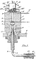
- -Fig. 1 is a longitudinal section of a switch element mounted on an on-column type injector, in an automatic sampling machine;
- -Fig. 2 is a detailed view of the switch element of Fig. 1;
- -Fig 3 is a side view of the device driving the sample injection needle, with the needle itself partially inserted in the switch element;
- -Fig. 4 is a view of the device driving the sample injection needle similar to that of the preceding Fig. but with the needle itself totally introduced in the injector.
- Referring to aforementioned Figs., reference 1 indicates the body of an on-column type injector, for instance such as the one described and illustrated in the U.S. patent No. 4.269.608.
- The injector body 1 shows a
duct 2 for the passage of theneedle 3 of a syringe for injection of the sample to be analyzed, connected to an automatic sampler known in itself, and it is fixed to the upper wall 4 of an oven where a gaschromatographic column 25 is housed. A duct 6 allows to introduce carrier gas into theduct 2, downstream thevalve 7 closing the latter. - The
duct 2 can be washed, in the period between subsequent injections, by inert gas, for instance nitrogen, and for this purpose the valve can optionally have an L-shaped secondary duct 7' which, when the valve is closed, as illustrated in the Fig., connects aduct 7" sending gas to theduct 2, which on its turn communicates with an upper exhaust opening 2' provided in the body 1 and controlled by avalve 2". Theseducts 2' and 2" can be also dispensed with, maintaining a good injector operation, but they are suitable for particular conditions. - A
switch element 10 is mounted on the injector body, in correspondence to the inlet section ofduct 2, by means of a bayonet joint and aseal gasket 9. - The
switch element 10 consists of acylindrical body 11 made of metal, axially bored, the upper end of which can be closed by means of ascrew cap 12 also provided with an axial hole 12'. Inside thebody 11, starting from its top, there are arubber septum 13, anelement 14 made of stiff chemically inert plastic material (for instance Teflon reg. T.M.) and theseal gasket 9, which has the shape of a so-called "pierced septum". Thecap 12 presses the seal or piercedseptum 9 against the injector body and allows saidseptum 9 to carry out a sealing action between theswitch element 10 and theinjector duct 2. Theelement 14 has an axial throughhole 15 which, at its bottom end, becomes larger to form asmall chamber 16 and then to form aseat 17 for partly housing thegasket 9. - The
rubber septum 13 is thin and the gasket orseptum 9 is pre-pierced coaxially to thehole 15, in order to allow an easy passage of theneedle 3 of the injection syringe. - The
element 14, besides theaxial hole 15, shows tworadial holes duct 15 and, through ahole 20, with thechamber 16 respectively.Other holes radial holes element 14 and are provided in the cylindrical envelope ofbody 11; they allow to connectduct 15, by fittings 21' and 22' andducts 21" and 22", to a gas source (duct 22") and to a collecting tank or an exhaust for the washing liquid or the exceeding sample (duct 2T). - The end of a pre-column 5 (i.e. a capillary tube without stationary phase) is inserted in the bottom end of injector duct 2 (Fig. 1). Said pre-column 5 is sealingly fixed to the injector body by means of a
gasket 26 and is connected, at its opposite end, to the gaschromatographic column 25 by means of ajoint 27 which can be of any known type. - In order to allow the use of syringe needles sufficiently resistant to pass through the
septum 9 without being deformed, the internal diameter of pre-column 5 is greater than or equal to 0.5 mm. - As a consequence, also the
injector duct 2 has a diameter greater than or equal to 0.5 mm as well as the passage for the syringe needle in theswitch element 10. - The following description of the injection steps of a sample to be analyzed and washing steps of the automatic sampler will make clear the
element 10 operation. - During operation of the automatic sampler, the
needle 3 of the injection syringe is inserted into theelement 10 and moves between a top position (illustrated in the Figs. 1 and 2), in which the needle tip is located between theseptum 13 and theradial hole 18, and a bottom position in which the needle tip is located inside the pre-column 5, essentially in the position indicated by the reference A in Fig. 1. - The steps of washing and elimination of the excess of sample injected to perform a subsequent analysis correspond to the needle top position, while the step of sample introduction in the column corresponds to the needle bottom position.
- At the end of each injection the
needle 3 is moved to the top position and fed with washing liquid and then with the sample to be analyzed, which is drawn from a vial and sent to the syringe. Simultaneously, through thehole 19, theduct 15 receives a gas flow, the pressure of which is controlled in a way as to create a gaseous cap at the bottom end of theduct 15, under theneedle 3. - More detailedly, during this step the pressure of the gas coming out of the
hole 19 is such as to prevent the sample from flowing down through theduct 15, and from there, through the hole ofseptum 9, into the injector body. This object is achieved by controlling the gas flow rate and pressure so that the sample can come out of the needle and penetrate thehole 18, but cannot go down in theduct 15 and reach theseptum 9. - When the injection syringe and the needle are filled with the sample and the needle is no longer introduced, the device actuating the
needle 3 movements stops for a time period which can be regulated and is necessary for the gas coming fromradial hole 19 to eliminate any sample trace from both theduct 15 and the external walls of theneedle 3. - During the subsequent needle motion, said gas flow is able to dry the outer needle wall to avoid any injector pollution. In order to improve the above gas action, the
element 14, immediately below its top end, can show aradial hole 23 coaxial to acorresponding hole 24 provided in thecylindrical envelope 11 of theelement 10, which allows the gas to go up along the side walls of the needle and to dry them as far as near therubber septum 13, then flowing out through the fitting 24' andduct 24". Thisduct 24" can be controlled by a suitable exhaust valve (not shown). - When this time period is over, the device controlling the
needle 3 movements actuates again the needle which reaches the bottom position of sample injection into the gas chromatographic capillary column. It should be noticed that, thanks to the drying action performed by the gas introduced through thehole 19, no sample trace is dragged by theneedle 3 through theseptum 9 into the injector. - At the end of the injection step and when the needle is up again, the washing cycle of the whole path of the injected sample begins, starting from the sample drawing end to the needle tip.
- In order to avoid that sample residues present in the syringe and in the needle as well as the washing fluid itself might go beyond the
rubber septum 9 penetrating theduct 2 of the injector, gas is fed through thehole 19. In this way, as during the step of sample metering, the washing liquid is pushed by the gas action into thehole 18 from which, through a suitable duct connected to thehole 21, it flows into a container or an exhaust opening. When any trace of the previously injected sample has been eliminated from the needle and syringe, feeding of the injection syringe with washing liquid is cut down while gas feeding to thehole 19 still continues; in this way the syringe needle is dried by the gas which eliminates any remaining trace of washing liquid. The automatic sampler is thus made available for providing a new sample to the injection syringe, theelement 10 and theduct 2 of the injector being perfectly clean. - During this step, it is possible to wash the
lower valve 7 as shown in Fig. 1 through theducts 7", 7' and 2'. It must be noticed that in case thevalve 7, which is automatically controlled, is able to carry out washing ofduct 2 when the needle is removed, as described above, said valve can have a configuration such as that described in the EP-A-32560. - Figures 3 and 4 show a device driving the needle for sample injection; said device comprises: a
support 30 holding in its lower part theneedle 3 and in its upper part aduct 31 from which the sample to be analyzed is introduced; said support is integral to avertical tube 32, the bottom end of which receives in a telescopic way atube 33 to which a small arm 33' is fixed; in the bottom end of the tube 33 asmall cylinder 34 provided on its turn with asmall arm 35 is inserted. - The
tube 32 driving thesupport 30 is fixed, on its turn, by means of asmall arm 36, to a hydraulic orpneumatic piston 37 controlling the up and down movements of theneedle 3. The injection needle is inserted in a suitable hole 36' provided in thesmall arm 36 and is fixed therein by ascrew 38. - The
tubes small cylinder 34 are kept spaced between one another by the action ofsprings vertical rod 41. Thevertical rod 41 is coaxial to thetubes small cylinder 34 and presents, at its top end, alock 43 capable of maintaining, against the action ofsprings small cylinder 34 and thetubes - The
small arms 33' and 35 are each provided with apierced rubber septum 42, in which theinjection needle 3 is inserted in a sliding way. The holes in thesepta 42 are strictly aligned with each other and with the hole 36' of thesmall arm 36. In this way the needle is kept straight during its movements by the superimposed and spaced small arms, the movements of which occuralong a way which is parallel to the ideal run of the needle. - In particular, when the needle goes down, the small arms go down jointly and, thanks to the action of the
springs small arm 35 goes against the support of theswitch element 10. The needle continues its down run and the small intermediate arm 33' reaches the lowersmall arm 35. Simultaneously thesmall cylinder 34 enters thetube 33 and thespring 40 is compressed. Finally thesmall arm 36 reaches the small arm 33', thetube 33 enters thetube 32 and thespring 39 is compressed. This condition corresponds to the complete insertion of the needle in the injector. When thepiston 37 actuates the upward movement of the needle, the action of thesprings
Claims (9)
Priority Applications (1)
| Application Number | Priority Date | Filing Date | Title |
|---|---|---|---|
| AT84110549T ATE48190T1 (en) | 1983-09-14 | 1984-09-05 | AUTOMATIC SAMPLE DEVICE AND SAMPLE PROCEDURE. |
Applications Claiming Priority (6)
| Application Number | Priority Date | Filing Date | Title |
|---|---|---|---|
| IT2297883U | 1983-09-14 | ||
| IT2297883U IT8322978V0 (en) | 1983-09-14 | 1983-09-14 | AUTOMATIC SAMPLING EQUIPMENT. |
| IT2155784 | 1984-06-22 | ||
| IT21557/84A IT1175543B (en) | 1984-06-22 | 1984-06-22 | Non-vaporising on column injector for capillary gas chromatography |
| IT2243384U IT8422433V0 (en) | 1984-06-29 | 1984-06-29 | AUTOMATIC SAMPLING EQUIPMENT IN GAS-CHROMATOGRAPHIC COLUMNS. |
| IT2243384U | 1984-06-29 |
Publications (2)
| Publication Number | Publication Date |
|---|---|
| EP0141148A1 EP0141148A1 (en) | 1985-05-15 |
| EP0141148B1 true EP0141148B1 (en) | 1989-11-23 |
Family
ID=27273197
Family Applications (1)
| Application Number | Title | Priority Date | Filing Date |
|---|---|---|---|
| EP84110549A Expired EP0141148B1 (en) | 1983-09-14 | 1984-09-05 | Automatic sample apparatus and sampling method |
Country Status (3)
| Country | Link |
|---|---|
| US (1) | US4621534A (en) |
| EP (1) | EP0141148B1 (en) |
| DE (1) | DE3480562D1 (en) |
Cited By (2)
| Publication number | Priority date | Publication date | Assignee | Title |
|---|---|---|---|---|
| US8057756B2 (en) | 2005-01-28 | 2011-11-15 | Parker-Hannifin Corporation | Sampling probe, gripper and interface for laboratory sample management systems |
| US8187535B2 (en) | 2004-06-14 | 2012-05-29 | Parker-Hannifin Corporation | Robotic handling system and method with independently operable detachable tools |
Families Citing this family (25)
| Publication number | Priority date | Publication date | Assignee | Title |
|---|---|---|---|---|
| FR2587123B1 (en) * | 1985-09-11 | 1988-07-08 | Rhone Poulenc Rech | DEVICE FOR INJECTING A LIQUID PRODUCT INTO A CHROMATOGRAPHY COLUMN |
| US4888998A (en) * | 1986-07-11 | 1989-12-26 | Beckman Instruments, Inc. | Sample handling system |
| US4815325A (en) * | 1988-04-22 | 1989-03-28 | Dynatech Precision Sampling Corporation | Capillary fluid injectors |
| US5213762A (en) * | 1989-03-13 | 1993-05-25 | Beckman Instruments, Inc. | Automatic chemistry analyzer |
| US5223222A (en) * | 1989-03-13 | 1993-06-29 | Beckman Instruments, Inc. | Automatic chemistry analyzer |
| US5130095A (en) * | 1989-03-13 | 1992-07-14 | Beckman Instruments, Inc. | Automatic chemistry analyzer |
| US5132233A (en) * | 1989-03-13 | 1992-07-21 | Beckman Instruments, Inc. | Sample injection cell |
| US5447055A (en) * | 1993-02-09 | 1995-09-05 | Tracer Research Corporation | Automated leak detection apparatus and method |
| JP3116821B2 (en) * | 1996-04-30 | 2000-12-11 | 株式会社島津製作所 | Auto injector |
| US6257076B1 (en) * | 1999-01-26 | 2001-07-10 | Merlin Instrument Company | Sample injector with plunger release for chemical analysis systems |
| US20060101899A1 (en) * | 2004-11-18 | 2006-05-18 | Hastings Mitchell R | Gas chromatography sample introduction devices and methods of using the same |
| WO2007067540A1 (en) | 2005-12-05 | 2007-06-14 | Parker-Hannifin | Self-cleaning injection port for analytical applications |
| EP1963868A2 (en) * | 2005-12-08 | 2008-09-03 | Parker Hannifin Corporation | Syringe wash station for analytical applications |
| EP2061420A1 (en) * | 2006-09-06 | 2009-05-27 | Thermo Electron S.p.A. | Washing device for liquid chromatography injectors |
| US8739610B2 (en) * | 2008-10-16 | 2014-06-03 | Shimadzu Corporation | Sample injection port and auto-sampler having the same |
| EP2261676B8 (en) * | 2009-06-12 | 2015-03-18 | CTC Analytics AG | Tool for handling a sample |
| EP2524213B1 (en) * | 2010-01-11 | 2024-03-06 | Waters Technologies Corporation | Injection port needle support and washing |
| WO2013069769A1 (en) | 2011-11-11 | 2013-05-16 | 積水メディカル株式会社 | Sample injection device for biochemical analysis, flow-type biochemical analysis device, and measurement method for hemoglobin component |
| CN107831043B (en) * | 2017-12-05 | 2024-01-12 | 上海新漫传感科技有限公司 | Tritiated water sampling bottle and sampling device of tritiated water sampler |
| EP3775871B1 (en) * | 2018-03-29 | 2023-09-13 | Waters Technologies Corporation | Autosampler seal pack for reducing a carryover percentage |
| KR102139431B1 (en) * | 2019-04-02 | 2020-07-29 | 박웅기 | Gas Chromatography Column Cleaner |
| CN111024640A (en) * | 2019-12-27 | 2020-04-17 | 安徽养和医疗器械设备有限公司 | Gas sample introduction device |
| CN114994222B (en) * | 2021-12-30 | 2023-03-24 | 青岛吉美来科技有限公司 | Portable detection device based on gas chromatography-mass spectrometry analysis principle |
| CN114964925B (en) * | 2022-04-29 | 2023-08-01 | 靖江中环信环保有限公司 | Waste gas sampling device for detecting waste gas of garbage combustion |
| CN117268837A (en) * | 2023-09-27 | 2023-12-22 | 安徽恒星建设工程有限公司 | Foundation intelligent detection sampling device and sampling method |
Family Cites Families (14)
| Publication number | Priority date | Publication date | Assignee | Title |
|---|---|---|---|---|
| AT286684B (en) * | 1965-05-19 | 1970-12-28 | Ceskoslovenska Akademie Ved | Device for sampling for automatic, physical-chemical analyzers |
| US3604269A (en) * | 1969-06-20 | 1971-09-14 | Upjohn Co | Automatic gas chromatographic sample injection device |
| GB1271812A (en) * | 1969-09-02 | 1972-04-26 | British Petroleum Co | Sample injection device |
| FR2120300A5 (en) * | 1970-12-29 | 1972-08-18 | Hoffmann La Roche | |
| US3842680A (en) * | 1972-08-09 | 1974-10-22 | Bach Simpson Ltd | Gas blast wiping collar for cleaning pipettes |
| US3841160A (en) * | 1973-03-05 | 1974-10-15 | Varian Associates | Automatic sampler apparatus |
| GB1445389A (en) * | 1973-10-16 | 1976-08-11 | Chemlab Mfg Ltd | Sampling arrangements |
| US4094195A (en) * | 1977-02-25 | 1978-06-13 | Waters Associates, Inc. | Novel seal and apparatus including same |
| US4094196A (en) * | 1977-02-25 | 1978-06-13 | Waters Associates, Inc. | Sample injection with automatic cleaning of sampling conduit |
| GB2030055B (en) * | 1978-09-26 | 1983-01-12 | Erba Strumentazione | Sample injection into gas chromatorgraphic columns |
| IT1209297B (en) * | 1980-01-02 | 1989-07-16 | Erba Strumentazione | INJECTION PASSAGE CONTROL VALVE FOR A DIRECT INJECTOR IN GAS-CHROMATOGRAPH COLUMN AND INJECTION PROCEDURE USING SUCH VALVE. |
| IT1129796B (en) * | 1980-01-25 | 1986-06-11 | Erba Strumentazione | DEVICE FOR THE AUTOMATION OF AT LEAST ONE OF THE FUNCTIONS OF AN INJECTOR FOR GAS-CHROMATOGRAPHIC COLUMNS |
| FR2491215A1 (en) * | 1980-09-26 | 1982-04-02 | Prolabo Sa | DEVICE FOR ASSOCIATING A PRECOLONNE AND COLUMN IN CHROMATOGRAPHY, USE OF SAID DEVICE FOR PRODUCING AN INDUSTRIAL AUTOMATIC CHROMATOGRAPH |
| US4516437A (en) * | 1983-03-23 | 1985-05-14 | Coulter Corporation | Microsample handling apparatus |
-
1984
- 1984-09-05 DE DE8484110549T patent/DE3480562D1/en not_active Expired
- 1984-09-05 EP EP84110549A patent/EP0141148B1/en not_active Expired
- 1984-09-06 US US06/647,986 patent/US4621534A/en not_active Expired - Fee Related
Cited By (2)
| Publication number | Priority date | Publication date | Assignee | Title |
|---|---|---|---|---|
| US8187535B2 (en) | 2004-06-14 | 2012-05-29 | Parker-Hannifin Corporation | Robotic handling system and method with independently operable detachable tools |
| US8057756B2 (en) | 2005-01-28 | 2011-11-15 | Parker-Hannifin Corporation | Sampling probe, gripper and interface for laboratory sample management systems |
Also Published As
| Publication number | Publication date |
|---|---|
| US4621534A (en) | 1986-11-11 |
| DE3480562D1 (en) | 1989-12-28 |
| EP0141148A1 (en) | 1985-05-15 |
Similar Documents
| Publication | Publication Date | Title |
|---|---|---|
| EP0141148B1 (en) | Automatic sample apparatus and sampling method | |
| US4242909A (en) | Sample injector | |
| US3918913A (en) | Sampler-injector for liquid chromatography | |
| US4836038A (en) | Automated sampler-injector apparatus and method for sampling a quantity of sample and testing portions of said quantity | |
| CA1097101A (en) | Seal and apparatus including same | |
| US20080314412A1 (en) | Self-Cleaning Injection Port for Analytical Applications | |
| US4094196A (en) | Sample injection with automatic cleaning of sampling conduit | |
| US4199988A (en) | Sampling apparatus for chromatographic instruments | |
| CA1312744C (en) | Combined closed and open tube sampling apparatus and method | |
| US4704141A (en) | Apparatus for automatically transferring small quantities of liquid samples in gas chromatography | |
| US6159185A (en) | Automatic sampling device with a syringe | |
| JPH03183947A (en) | Doser for analyzer | |
| US4766760A (en) | Method of chromatographic analysis of a mixture of liquid substances and a gas chromatograph for carrying out the method | |
| KR101148509B1 (en) | Method and apparatus for liquid chromatography automated sample loading | |
| US3981200A (en) | Method of automatically transferring and injecting a liquid sample | |
| US20050092685A1 (en) | Set comprising a pipette and a cartridge, as well as a method for applying a sample to the cartridge and an analytical method | |
| US4558603A (en) | Needle assembly for introducing a carrier gas into a sample vessel | |
| EP0858588B1 (en) | Multifunction valve | |
| US4484483A (en) | Needle assembly useful in the head-space method of gas chromatography | |
| US4474588A (en) | Unheated septumless on-column injection system for capillary gas chromatography | |
| US4347215A (en) | Device for the automation of at least one operation in an injector for gas chromatographic columns | |
| EP3446131B1 (en) | Pressure controlled fluid sampler and method | |
| US3877310A (en) | Automatic sampler apparatus | |
| US7563410B2 (en) | Solid phase extraction apparatus and method | |
| US3733909A (en) | Apparatus for injecting a sample into a gas chromatograph |
Legal Events
| Date | Code | Title | Description |
|---|---|---|---|
| PUAI | Public reference made under article 153(3) epc to a published international application that has entered the european phase |
Free format text: ORIGINAL CODE: 0009012 |
|
| AK | Designated contracting states |
Designated state(s): AT BE CH DE FR GB LI NL SE |
|
| 17P | Request for examination filed |
Effective date: 19850921 |
|
| 17Q | First examination report despatched |
Effective date: 19870831 |
|
| GRAA | (expected) grant |
Free format text: ORIGINAL CODE: 0009210 |
|
| AK | Designated contracting states |
Kind code of ref document: B1 Designated state(s): AT BE CH DE FR GB LI NL SE |
|
| PG25 | Lapsed in a contracting state [announced via postgrant information from national office to epo] |
Ref country code: SE Effective date: 19891123 Ref country code: LI Effective date: 19891123 Ref country code: CH Effective date: 19891123 Ref country code: BE Effective date: 19891123 Ref country code: AT Effective date: 19891123 |
|
| REF | Corresponds to: |
Ref document number: 48190 Country of ref document: AT Date of ref document: 19891215 Kind code of ref document: T |
|
| REF | Corresponds to: |
Ref document number: 3480562 Country of ref document: DE Date of ref document: 19891228 |
|
| ET | Fr: translation filed | ||
| REG | Reference to a national code |
Ref country code: CH Ref legal event code: PL |
|
| PGFP | Annual fee paid to national office [announced via postgrant information from national office to epo] |
Ref country code: FR Payment date: 19900816 Year of fee payment: 7 |
|
| PGFP | Annual fee paid to national office [announced via postgrant information from national office to epo] |
Ref country code: GB Payment date: 19900904 Year of fee payment: 7 |
|
| PLBE | No opposition filed within time limit |
Free format text: ORIGINAL CODE: 0009261 |
|
| STAA | Information on the status of an ep patent application or granted ep patent |
Free format text: STATUS: NO OPPOSITION FILED WITHIN TIME LIMIT |
|
| PGFP | Annual fee paid to national office [announced via postgrant information from national office to epo] |
Ref country code: NL Payment date: 19900930 Year of fee payment: 7 |
|
| PGFP | Annual fee paid to national office [announced via postgrant information from national office to epo] |
Ref country code: DE Payment date: 19901030 Year of fee payment: 7 |
|
| 26N | No opposition filed | ||
| PG25 | Lapsed in a contracting state [announced via postgrant information from national office to epo] |
Ref country code: GB Effective date: 19910905 |
|
| PG25 | Lapsed in a contracting state [announced via postgrant information from national office to epo] |
Ref country code: NL Effective date: 19920401 |
|
| GBPC | Gb: european patent ceased through non-payment of renewal fee | ||
| NLV4 | Nl: lapsed or anulled due to non-payment of the annual fee | ||
| PG25 | Lapsed in a contracting state [announced via postgrant information from national office to epo] |
Ref country code: FR Effective date: 19920529 |
|
| PG25 | Lapsed in a contracting state [announced via postgrant information from national office to epo] |
Ref country code: DE Effective date: 19920602 |
|
| REG | Reference to a national code |
Ref country code: FR Ref legal event code: ST |