US4182184A - Sample injector - Google Patents
Sample injector Download PDFInfo
- Publication number
- US4182184A US4182184A US05/969,331 US96933178A US4182184A US 4182184 A US4182184 A US 4182184A US 96933178 A US96933178 A US 96933178A US 4182184 A US4182184 A US 4182184A
- Authority
- US
- United States
- Prior art keywords
- tube
- needle
- receiving passage
- rotor
- passage
- Prior art date
- Legal status (The legal status is an assumption and is not a legal conclusion. Google has not performed a legal analysis and makes no representation as to the accuracy of the status listed.)
- Expired - Lifetime
Links
Images

Classifications
-
- G—PHYSICS
- G01—MEASURING; TESTING
- G01N—INVESTIGATING OR ANALYSING MATERIALS BY DETERMINING THEIR CHEMICAL OR PHYSICAL PROPERTIES
- G01N30/00—Investigating or analysing materials by separation into components using adsorption, absorption or similar phenomena or using ion-exchange, e.g. chromatography or field flow fractionation
- G01N30/02—Column chromatography
- G01N30/04—Preparation or injection of sample to be analysed
- G01N30/16—Injection
- G01N30/22—Injection in high pressure liquid systems
Definitions
- sample injection devices which accept variable volumes of sample, transferred into the injector via an injector opening which accepts the needle of a micro syringe.
- the syringe serves to measure the volume of the introduced sample.
- the sample then resides in a chamber, often referred to as the sample loop, which is at atmospheric pressure.
- the sample is swept at a high pressure, of typically 100 to 10,000 psi, from the chamber and into the column by the flow of mobile phase from the pump.
- One type of prior art injector device has a needle-receiving passage from which the syringe is withdrawn subsequent to the transfer of sample into the chamber, and which must be plugged prior to the actuation of the injector. The plug prevents loss of high pressure fluid from the port.
- Such devices are described in U.S. Pat. Nos. 3,916,692 by Abrahams et al and 3,961,534 by Gundelfinger.
- One advantage of such devices is that all of the sample transferred by the syringe is subsequently injected into the column, so there is no sample loss. This is beneficial because the syringe calibration marks on a conventional syringe provide an accurate indication of the volume actually injected into the column.
- An object of this invention is to provide an injector device which is easy to use, avoids wastage of sample, avoids cross-contamination of samples, and accurately delivers a sample to a chromatographic column in accordance with standard syringe calibrations.
- a relatively simple and easily operated sample injector device which avoids the entrappment of the sample.
- the device includes stator and rotor elements with axially-facing adjacent surfaces, with one of the elements having a needle opening or passage for receiving a syringe needle, and with the other element having a port that can be aligned with the needle passage to receive the sample transferred through the needle.
- the needle passage extends parallel to, but offset from, the axis of rotation of the rotor.
- the tip of the syringe needle is ground flat and perpendicular to its axis.
- the tip When the needle is fully inserted into the needle passage of the rotor element, the tip is in contact with the flat face of the stator element so that there is no connecting volume between the tip of the syringe needle and the aligned stator element port. The entire volume discharged by the syringe is then transferred to the sample loop via this port.
- FIG. 1 is a partial sectional view of a prior art sample injector.
- FIG. 2 is a partial sectional view of another prior art sample injector.
- FIG. 3 is a partially sectional perspective view of a sample injector constructed in accordance with one embodiment of the present invention.
- FIG. 4 is a view taken on the line 4--4 of FIG. 3.
- FIG. 5 is an enlarged view of the region 5--5 of FIG. 4.
- FIG. 6 is a simplified exploded view of the sample injector of FIG. 4, shown in a load configuration.
- FIG. 7 is a view taken on the line 7--7 of FIG. 6.
- FIG. 8 is a simplified exploded perspective view of the device of FIG. 6, but shown in an inject configuration.
- FIG. 9 is a view taken on the line 9--9 of FIG. 8.
- FIG. 9A is a partial sectional view of another sample injector.
- FIG. 10 is a partial sectional view of a sample injector constructed in accordance with another embodiment of the invention.
- FIG. 11 is a partial sectional view of a sample injector device constructed in accordance with another embodiment of the invention.
- FIG. 12 is a simplified exploded perspective view of the device of FIG. 11, shown in a load configuration, and after the sample has been loaded into the sample loop.
- FIG. 13 is a view similar to FIG. 12, but showing the device after it has been turned to an inject configuration, and showing the device operated in a flush mode to prevent cross contamination after syringe needle removal.
- FIG. 14 is a simplified exploded perspective view of a sample injector constructed in accordance with another embodiment of the invention.
- FIG. 1 illustrates one prior art sample injector, which includes a rotor 10 that lies within a cylindrical stator 12 that has a hole 14 for receiving the needle 16 of a syringe.
- the tip 20 of the needle lies behind the rotor-stator interface 22. Accordingly, when the rotor 10 is turned to pump the sample out of the passage 18, some of the sample will lie in a connecting passage 24 at the end of the needle-receiving hole.
- FIG. 2 illustrates another prior art sample injector, which includes a rotor 30 having a needle receiving hole portion 32 for receiving a needle 34.
- the hole portion 32 lies along the axis of rotation 36 of the rotor, and another hole portion 38 extending in a largely radial direction is provided to carry the sample to a stator port 40 spaced from the axis 36.
- the hole portion 38 extends largely radially to enable disconnection thereof from the stator port 40 when the rotor turns.
- the hole portion 38 holds a portion of the sample which is not utilized and which is therefore wasted. In both of the foregoing prior art sample injectors, some sample is wasted, and the sample remaining in the connecting passage is a source of cross contamination if it is not flushed out prior to the next injection.
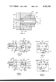
- FIG. 3 illustrates a sample injector of the present invention, which can receive a small sample from a micro syringe 52 and deliver the sample along a conduit 54 to a chromatographic column or other analytical device, without incurring any sample loss.
- the device includes a stator element or stator 56 and a rotor element or rotor 58 that rotates about an axis 60.
- the stator and rotor have adjacent faces 62, 64 that each face in an axial direction, that is, each face extends normal to the axis of rotation 60.
- the stator has a group of six ports 66 that extend to the stator face 62.
- the rotor 58 has a frame with a group of openings or passages 68 spaced about the axis 60, that are open to the rotor face 64, so that they can communicate with the stator ports 66.
- One of the rotor passages 68A is a needle-receiving passage which is designed to receive the tube or needle 70 of the micro syringe.
- the other passages 68 in the rotor are arranged in interconnected pairs, and are utilized to interconnect selected pairs of stator ports 66.
- the rotor 58 can rotate, or pivot, about the axis 60 between two positions, to connect the needle-receiving passage 68A to different ports 66, and to utilize the other rotor passages 68 to interconnect different pairs of ports.
- FIGS. 6-9 wherein the stator ports are labelled P 1 through P 6 , show the injector device in two different positions.
- the sample injector device 50 is in a "load" configuration, wherein the rotor 58 is positioned so that the rotor passage 68A is aligned with stator port P 4 .
- the solvent being pumped through the chromatographic system from the pump is connected to port P 2 , and the column is connected to port P 3 .
- the sample loop 72 is connected to ports P 1 and P 4 .
- Ports P 5 and P 6 are connected to vent tubes and are always at atmospheric pressure.
- the sample loop 72 is made long enough to contain a volume of liquid greater than the largest sample volume to be introduced by the syringe. In operation, the sample loop contains solvent (from the pump) prior to the transfer of sample from the syringe into the loop.
- the operator can insert the needle 70 of the micro-syringe into the needle-receiving passage 68A, and then discharge the syringe to transfer the sample into the port P 4 which is aligned therewith.
- the sample flows through the port P 4 into the sample loop 72 connected therewith, and displaces an equal volume of solvent in the loop, through a vent port P 6 via the rotor passage 68C, rotor passage 74, and rotor passage 68B.
- the pumped solvent flows directly to the column via the rotor passage 80 which joins rotor passages 68D and 68E.
- the sample in the load position of the rotor 58 shown in FIG. 6, and also as indicated in FIG. 7, the sample can be transferred at atmospheric pressure into the sample loop 72 to prepare it for a subsequent high pressure injection into the chromatographic column.
- FIGS. 8 and 9 illustrate the device 50 when it is in the "inject" position, wherein the rotor 58 has been turned in the direction of arrow 76 by an angle of 60°, so that the rotor passage 68A is now aligned with the stator port P 5 .
- solvent pumped by a high pressure pump 78 can flow through port P 2 , through rotor opening 68C and through passage 74 to rotor opening 68B, through port P1, and through the sample loop 72.
- the sample lying in the loop 72 is thereby moved along by the solvent through the port P 4 , through rotor opening 68E and a passage 80 to rotor opening 68D, and through port P 3 , to flow the sample along a line 82 leading to the chromatographic column.
- the sample loop 72 was initially filled with the sample at atmospheric pressure, the sample now can be pumped into the column under a high pressure (such as up to 10,000 psi) applied by the pump 78. All portions of the sample lying in the sample loop 72 and in the port P 4 will be pumped to the column.
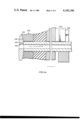
- the rotor includes a guide tube 102 for receiving the syringe needle 70.
- the needle is inserted into an opening 104 in the guide tube 102, passes through a seal 100, passes through the end of the rotor passage 68A, and abuts the flat face 62 of the stator.
- the seal is made of relatively easily compressible plastic such as polytetrafluroethylene and is compressed sufficiently by screwing in the guide tube 102 so that the seal hole squeezes tightly around the syringe needle to form a liquid-tight seal.
- the rotor passage 68A and the hole in the seal 100 are filled with solvent before inserting the syringe needle.
- the needle When the needle is inserted, it is therefore surrounded by solvent and the seal effectively traps the solvent in the clearance space 103 surrounding the end of the needle, in the portion of the rotor passage 68A lying between the seal 100 and the stator face 62. Accordingly, any tendency for the sample that is discharged from the syringe to leak back out through the needle guide is prevented.
- the parallel flat face contact between the needle tip 92 and stator face 62 is precise enough to limit diffusion of sample liquid away from port P 4 , to a negligible amount.
- a major novelty of the present invention concerns the discovery that the flat syringe needle tip 92 can be pushed in to abut the stator face 62, and can be left there while the rotor 58 is turned so that face of tip 92 slides along the stator face 62.
- FIG. 5 shows that the diameter of the stator port 66 is smaller than the outer diameter of the needle, preventing the needle from entering the port. Since the sliding action of the needle tip 92 against the stator face 62 can cause wear, the stator should be made of a material that is substantially harder than the needle.
- FIG. 5 shows a thin layer 94 which forms a hard surface on the stator face. Hard surface coatings of ceramic materials are commonly available for this purpose.
- the area contact between the flat tip of the needle which lies in a plane parallel to the flat stator face, minimizes the possibility of scratching a groove in the stator face during turning of the rotor by wear or microscopic chipping and crumbling.
- the rotor is rotatably mounted on a shaft 118 (FIG. 3) and can be turned by turning a handle 124.
- This arrangement provides a 360° seal between the needle tip and rotor port, and also provides area contact of the needle face with the rotor surface to minimize wear or chipping of the rotor surface. It may be noted that it is possible to utilize a spherical outer surface in the rotor around the port 126 therein, to achieve 360° sealing contact around the port, although there would not be area contact with the needle and a spherical surface is more expensive to form. Area contact with a spherical element surface can be achieved by grinding the needle tip to a matching spherical form, but this is also more expensive.
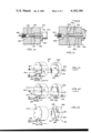
- a device of the type shown at 130 in FIG. 10 can be utilized to inject a sample without entrapment and loss of sample.
- the device of FIG. 10 is utilized by inserting the syringe needle 70A through a rotor passage 132 of a rotor 134, until the tip 136 of the needle passes across the stator face 138 and lies in the aligned stator port 140.
- a stop 142 limits the depth of insertion of the needle until the stop abuts a shoulder on the micro syringe.
- the micro syringe 52 A is then operated to transfer the sample into the port 140 and into a sample loop 144 connected thereto.
- the syringe is then withdrawn so that the needle tip 136 lies behind the stator face 138, and the rotor is then turned by 60° to couple the high pressure pump to the sample tube 144 and to connect the port 140 to a rotor passage that leads to the column in the manner described above for the device for FIGS. 1-9.
- FIG. 11 illustrates a sample injection device which has the advantage of the device illustrated in FIG. 4 of not requiring further manipulation of the syringe once it has been inserted, but which is similar to the device of FIG. 10 in that the needle tip is not located at the rotor-stator interface in contact with the stator face.
- a flush channel 152 is provided which leads to the end portion of the needle passage 154 in which the needle 70B lies.
- a quantity of flushing fluid such as the same solvent that is used to later pump the sample into the chromatographic column, is flushed through the passage 152, around the end of the needle 70B which lies beyond the seal 156, and into the stator port 158, to flush all of the sample into the port 158 and into the sample loop 160 connected thereto. Only a small amount of flushing fluid is passed through the passage 152, so that only a small amount of solvent will lie in the sample loop 160. The flushing permits the tip 162 of the needle to lie behind the stator face 164 at all times, to avoid contact with the stator face, and yet prevent loss of the injected sample.
- FIGS. 12-13 illustrate additional details of the flushing type sample injection device 150 of FIG. 11.
- FIG. 12 shows the rotor 166 in the "load" position, wherein the rotor needle passage 154 is aligned with the port 158, so that the sample can be transferred into the sample loop 160.
- a flushing syringe 168 is operated.
- the flushing syringe is connected to a port P 5 which is aligned with an opening 170 in the rotor that leads to the flushing pasage 152, so that operation of the flushing syringe causes the flushing fluid to flow through the passage 152 and flush out any sample remaining in the needle passage 154.
- the rotor After the sample has been loaded and the flushing syringe 168 operated, the rotor is turned 60° to the position shown in FIG. 13, wherein the port P 4 is connected to another rotor opening 172, to allow the pumping of the small amount of flushing fluid and sample lying in the loop 160, into the chromatographic column. In this inject position of the rotor, the needle passage 154 of the rotor becomes aligned with the port P 5 to which the flushing syringe 168 is connected.
- FIG. 14 illustrates a modified flushable sample injection device 180 which is similar to the device 150 of FIGS. 11-13, except that it permits automatic refilling of the flushing syringe 168. This is accomplished by the use of a recharging passage 182 which is formed in the rotor. The ends 186, 188 of the recharging passage are located so that they are in line with the stator port P 1 and the flushing port P 5 for a brief time as the rotor 184 is being rotated between the load and inject positions of FIGS. 12 and 13 respectively.
- the invention provides a sample injector device of the type which can receive a sample to be analyzed by transfer from a syringe at atmospheric pressure, and then inject the sample at high pressure into a chromatographic column or other analyzing instrument, which avoids the loss of any sample while enabling operation of the device in a relatively simple manner.
- This can be accomplished by utilizing rotor and stator elements having axially facing surfaces, so that the surfaces can be flat at least around the communicating holes therein, and by utilizing a needle-receiving opening that receives an injection needle so that the needle can be received up against the face of the other element and can remain thereat during turning of the rotor.
- the needle-receiving opening which may be formed in the rotor, extends along a straight line that is parallel to the axis of rotation but which is radially offset therefrom.
- the orientation of the needle-receiving opening parallel to the axis permits a needle with a tip perpendicular to the axis of the needle, to lie in sealing contact with the flat face of the engaged element around the port therein, to prevent the leakage of sample into the clearance space around the end of the needle.
- This arrangement also provides area contact of the needle tip against the face of the other element such as the stator, and the needle can remain thereagainst while the rotor turns without scratching or chipping a groove in the face which the needle tip contacts during numerous operations of the device.
- the needle-receiving opening can be sealed against the outside of the needle by utilizing a seal of easily compressible material, and by providing a needle guide which is biased against the seal to axially compress it so that the seal then presses tightly against the injection tube, to provide a backup seal that avoids backward leakage of the sample.
- a backup seal of slippery material such as Teflon, avoids springing back when pressure on the syringe is released, so that such a backup seal can hold the needle flush against the element face even though the operator stops applying force.
- the backup seal can extend up to the element interface.
- the device is constructed so that the tip of the needle passes the rotor-stator interface, where it remains during atmospheric pressure transfer of sample from the syringe, and wherein the needle is withdrawn behind the rotor-stator interface before the rotor is turned.
- the tip of the needle can lie behind the rotor-stator interface, but a flushing passage is provided which leads to the end of the needle-receiving opening, to flush any remaining sample therein into the other element prior to the rotation of the rotor.
- sample transfer tubes other than those on syringes can be utilized, and the term needle is herein utilized to refer to any small diameter tube.
- the needle-receiving passage can be formed in a stator element instead of a rotor element.
Abstract
Description
Claims (23)
Priority Applications (1)
| Application Number | Priority Date | Filing Date | Title |
|---|---|---|---|
| US05/969,331 US4182184A (en) | 1978-12-14 | 1978-12-14 | Sample injector |
Applications Claiming Priority (1)
| Application Number | Priority Date | Filing Date | Title |
|---|---|---|---|
| US05/969,331 US4182184A (en) | 1978-12-14 | 1978-12-14 | Sample injector |
Publications (1)
| Publication Number | Publication Date |
|---|---|
| US4182184A true US4182184A (en) | 1980-01-08 |
Family
ID=25515435
Family Applications (1)
| Application Number | Title | Priority Date | Filing Date |
|---|---|---|---|
| US05/969,331 Expired - Lifetime US4182184A (en) | 1978-12-14 | 1978-12-14 | Sample injector |
Country Status (1)
| Country | Link |
|---|---|
| US (1) | US4182184A (en) |
Cited By (33)
| Publication number | Priority date | Publication date | Assignee | Title |
|---|---|---|---|---|
| US4242909A (en) * | 1979-04-19 | 1981-01-06 | Rheodyne Incorporated | Sample injector |
| US4393726A (en) * | 1980-10-01 | 1983-07-19 | Bodenseeverk Perkin-Elmer & Co. Gmbh | Sampling valve useful in liquid chromatography |
| US4403520A (en) * | 1980-01-02 | 1983-09-13 | Carlo Erba Strumentazione S.P.A. | Control valve for a direct on-column injector and injection method |
| US4506558A (en) * | 1983-03-03 | 1985-03-26 | Rheodyne Incorporated | Injector with minimal flow-interrupt transient |
| US4792396A (en) * | 1987-11-03 | 1988-12-20 | Rheodyne Incorporated | Multi-size injector port system |
| FR2630214A1 (en) * | 1988-04-15 | 1989-10-20 | Kone Oy | LIQUID SELECTION METHOD FOR LIQUID DISPENSING OF AN ANALYZER, AND SAMPLING DEVICE |
| US5207109A (en) * | 1991-02-07 | 1993-05-04 | Rheodyne, Inc. | Internal-external sample injector |
| US5419208A (en) * | 1993-01-29 | 1995-05-30 | Upchurch Scientific, Inc. | Multiport selection valve |
| US6267143B1 (en) | 1999-06-29 | 2001-07-31 | Upchurch Scientific, Inc. | Selection valve with ferrule cluster |
| US20010038071A1 (en) * | 2000-04-26 | 2001-11-08 | Nichols Jon A. | Mass rate attenuator |
| KR100314574B1 (en) * | 1997-08-19 | 2002-10-11 | 바이오메뤼 비텍, 인코포레이티드 | Locking structure for securing fluid delivery line |
| US6632404B1 (en) | 2000-08-02 | 2003-10-14 | Symyx Technologies, Inc. | Automatically actuated parallel sample injector valve |
| US6729350B2 (en) * | 2001-05-25 | 2004-05-04 | Upchurch Scientific, Inc. | Valve for use with capillary tubing |
| US20050012327A1 (en) * | 2001-10-19 | 2005-01-20 | Owe Salven | Connector |
| US20050127097A1 (en) * | 2003-10-29 | 2005-06-16 | Rheodyne, Llc | Dosing engine and cartridge apparatus for liquid dispensing and method |
| US20060042686A1 (en) * | 2004-08-25 | 2006-03-02 | Controle Analytique Inc. | Rotary valve and analytical chromatographic system using the same |
| US20060090251A1 (en) * | 2004-11-01 | 2006-05-04 | Harbol Keith W | Fluid delivery system for a water tub using a removeable chemical carrier |
| WO2007067540A1 (en) * | 2005-12-05 | 2007-06-14 | Parker-Hannifin | Self-cleaning injection port for analytical applications |
| EP1843153A1 (en) * | 2005-01-24 | 2007-10-10 | Shiseido Company, Limited | Sample injector, sample injecting method and liquid chromatography equipment |
| US20070295113A1 (en) * | 2004-06-14 | 2007-12-27 | Parker-Hannifin Corporation | Robotic Handling System and Method with Independently Operable Detachable Tools |
| US20080156117A1 (en) * | 2005-01-28 | 2008-07-03 | Parker-Hannifin Corporation | Sampling Probe, Gripper and Interface For Laboratory Sample Management Systems |
| US20090032065A1 (en) * | 2005-12-08 | 2009-02-05 | Bantz Daniel L | Syringe wash station for analytical applications |
| WO2009040224A1 (en) * | 2007-09-27 | 2009-04-02 | Dani Instruments S.P.A. | Method for directly injecting a liquid sample into a capillary chromatography column and apparatus for implementing the method. |
| WO2010139359A1 (en) * | 2009-06-03 | 2010-12-09 | Agilent Technologies, Inc. | Sample injector with metering device balancing pressure differences in an intermediate valve state |
| CN102590400A (en) * | 2012-03-02 | 2012-07-18 | 天津市先权工贸发展有限公司 | Variable volume trace gas sampling valve |
| US20130139905A1 (en) * | 2010-07-01 | 2013-06-06 | Alfa Laval Corporate Ab | Flow module port fitting |
| CN104879532A (en) * | 2015-05-21 | 2015-09-02 | 青岛大学 | Variable thermal stability volume sample valve |
| US9194504B2 (en) | 2009-01-14 | 2015-11-24 | Waters Technologies Corporation | Rotating valve |
| EP2888595A4 (en) * | 2012-08-22 | 2016-04-13 | Ge Healthcare Bio Sciences Ab | Versatile rotary valve |
| US10012620B1 (en) | 2015-04-07 | 2018-07-03 | Sielc Technologies Corporation | Chromatography sample introduction device |
| US10386342B2 (en) | 2008-01-25 | 2019-08-20 | Dionex Softron Gmbh | Sample injector for liquid chromatography, particularly for high performance liquid chromatography |
| US10473631B2 (en) | 2015-06-25 | 2019-11-12 | Dionex Softron Gmbh | Sampler for liquid chromatography |
| CN115128203A (en) * | 2022-07-08 | 2022-09-30 | 北京捷思达仪分析仪器研发中心 | Automatic sample introduction device for thermal cracking chromatography |
Citations (4)
| Publication number | Priority date | Publication date | Assignee | Title |
|---|---|---|---|---|
| US3916692A (en) * | 1973-11-14 | 1975-11-04 | Waters Associates Inc | Novel injector mechanism |
| US3961534A (en) * | 1975-09-02 | 1976-06-08 | Richard Gundelfinger | Two position rotary valve for injecting sample liquids into an analysis system |
| US4022065A (en) * | 1976-02-19 | 1977-05-10 | Ramin James A | Calibrated sample delivery apparatus accommodating offset error |
| US4068528A (en) * | 1976-01-19 | 1978-01-17 | Rheodyne Incorporated | Two position rotary valve for injecting sample liquids into an analysis system |
-
1978
- 1978-12-14 US US05/969,331 patent/US4182184A/en not_active Expired - Lifetime
Patent Citations (4)
| Publication number | Priority date | Publication date | Assignee | Title |
|---|---|---|---|---|
| US3916692A (en) * | 1973-11-14 | 1975-11-04 | Waters Associates Inc | Novel injector mechanism |
| US3961534A (en) * | 1975-09-02 | 1976-06-08 | Richard Gundelfinger | Two position rotary valve for injecting sample liquids into an analysis system |
| US4068528A (en) * | 1976-01-19 | 1978-01-17 | Rheodyne Incorporated | Two position rotary valve for injecting sample liquids into an analysis system |
| US4022065A (en) * | 1976-02-19 | 1977-05-10 | Ramin James A | Calibrated sample delivery apparatus accommodating offset error |
Cited By (64)
| Publication number | Priority date | Publication date | Assignee | Title |
|---|---|---|---|---|
| US4242909A (en) * | 1979-04-19 | 1981-01-06 | Rheodyne Incorporated | Sample injector |
| US4403520A (en) * | 1980-01-02 | 1983-09-13 | Carlo Erba Strumentazione S.P.A. | Control valve for a direct on-column injector and injection method |
| US4393726A (en) * | 1980-10-01 | 1983-07-19 | Bodenseeverk Perkin-Elmer & Co. Gmbh | Sampling valve useful in liquid chromatography |
| US4506558A (en) * | 1983-03-03 | 1985-03-26 | Rheodyne Incorporated | Injector with minimal flow-interrupt transient |
| US4792396A (en) * | 1987-11-03 | 1988-12-20 | Rheodyne Incorporated | Multi-size injector port system |
| FR2630214A1 (en) * | 1988-04-15 | 1989-10-20 | Kone Oy | LIQUID SELECTION METHOD FOR LIQUID DISPENSING OF AN ANALYZER, AND SAMPLING DEVICE |
| US4974459A (en) * | 1988-04-15 | 1990-12-04 | Kone Oy | Procedure for implementing selection of liquids in liquid dispensing in an analyzer, and sampling device |
| US5207109A (en) * | 1991-02-07 | 1993-05-04 | Rheodyne, Inc. | Internal-external sample injector |
| US5419208A (en) * | 1993-01-29 | 1995-05-30 | Upchurch Scientific, Inc. | Multiport selection valve |
| KR100314574B1 (en) * | 1997-08-19 | 2002-10-11 | 바이오메뤼 비텍, 인코포레이티드 | Locking structure for securing fluid delivery line |
| US6267143B1 (en) | 1999-06-29 | 2001-07-31 | Upchurch Scientific, Inc. | Selection valve with ferrule cluster |
| US6390127B2 (en) * | 1999-06-29 | 2002-05-21 | Upchurch Scientific, Inc. | Selection valve with ferrule cluster |
| US20010038071A1 (en) * | 2000-04-26 | 2001-11-08 | Nichols Jon A. | Mass rate attenuator |
| US20050118075A1 (en) * | 2000-04-26 | 2005-06-02 | Nichols Jon A. | Mass rate attenuator |
| US7575723B2 (en) | 2000-04-26 | 2009-08-18 | Idex Health & Science Llc | Mass rate attenuator |
| US6890489B2 (en) * | 2000-04-26 | 2005-05-10 | Rheodyne, L.P. | Mass rate attenuator |
| US6632404B1 (en) | 2000-08-02 | 2003-10-14 | Symyx Technologies, Inc. | Automatically actuated parallel sample injector valve |
| US6729350B2 (en) * | 2001-05-25 | 2004-05-04 | Upchurch Scientific, Inc. | Valve for use with capillary tubing |
| US20050012327A1 (en) * | 2001-10-19 | 2005-01-20 | Owe Salven | Connector |
| US7338088B2 (en) * | 2001-10-19 | 2008-03-04 | Ge Healthcare Bio-Sciences Ab | Connector |
| US20080054630A1 (en) * | 2001-10-19 | 2008-03-06 | Ge Healthcare Bio-Sciences Ab | Connector |
| US7472928B2 (en) | 2001-10-19 | 2009-01-06 | Ge Healthcare Bio-Sciences Ab | Connector |
| US20050127097A1 (en) * | 2003-10-29 | 2005-06-16 | Rheodyne, Llc | Dosing engine and cartridge apparatus for liquid dispensing and method |
| US8431020B2 (en) | 2003-10-29 | 2013-04-30 | Idex Health & Science Llc | Dosing engine and cartridge apparatus for liquid dispensing and method |
| US20090266751A1 (en) * | 2003-10-29 | 2009-10-29 | Idex Health & Science Llc | Dosing engine and cartridge apparatus for liquid dispensing and method |
| US7544289B2 (en) | 2003-10-29 | 2009-06-09 | Idex Health & Science Llc | Dosing engine and cartridge apparatus for liquid dispensing and method |
| US8187535B2 (en) | 2004-06-14 | 2012-05-29 | Parker-Hannifin Corporation | Robotic handling system and method with independently operable detachable tools |
| US20070295113A1 (en) * | 2004-06-14 | 2007-12-27 | Parker-Hannifin Corporation | Robotic Handling System and Method with Independently Operable Detachable Tools |
| US7503203B2 (en) | 2004-08-25 | 2009-03-17 | Mecanique Analytique Inc. | Rotary valve and analytical chromatographic system using the same |
| US20060042686A1 (en) * | 2004-08-25 | 2006-03-02 | Controle Analytique Inc. | Rotary valve and analytical chromatographic system using the same |
| US7258783B2 (en) | 2004-11-01 | 2007-08-21 | Watkins Manufacturing Corporation | Fluid delivery system for a water tub using a removeable chemical carrier |
| US20060090251A1 (en) * | 2004-11-01 | 2006-05-04 | Harbol Keith W | Fluid delivery system for a water tub using a removeable chemical carrier |
| CN101107518B (en) * | 2005-01-24 | 2011-11-30 | 株式会社资生堂 | Sample injector, sample injecting method and liquid chromatography equipment |
| EP1843153A4 (en) * | 2005-01-24 | 2009-09-02 | Shiseido Co Ltd | Sample injector, sample injecting method and liquid chromatography equipment |
| EP1843153A1 (en) * | 2005-01-24 | 2007-10-10 | Shiseido Company, Limited | Sample injector, sample injecting method and liquid chromatography equipment |
| US20080156117A1 (en) * | 2005-01-28 | 2008-07-03 | Parker-Hannifin Corporation | Sampling Probe, Gripper and Interface For Laboratory Sample Management Systems |
| US8057756B2 (en) | 2005-01-28 | 2011-11-15 | Parker-Hannifin Corporation | Sampling probe, gripper and interface for laboratory sample management systems |
| US20080314412A1 (en) * | 2005-12-05 | 2008-12-25 | Grippo Paul M | Self-Cleaning Injection Port for Analytical Applications |
| WO2007067540A1 (en) * | 2005-12-05 | 2007-06-14 | Parker-Hannifin | Self-cleaning injection port for analytical applications |
| US20090032065A1 (en) * | 2005-12-08 | 2009-02-05 | Bantz Daniel L | Syringe wash station for analytical applications |
| WO2009040224A1 (en) * | 2007-09-27 | 2009-04-02 | Dani Instruments S.P.A. | Method for directly injecting a liquid sample into a capillary chromatography column and apparatus for implementing the method. |
| US20100192674A1 (en) * | 2007-09-27 | 2010-08-05 | Dani Instruments S.P.A. | Method for directly injecting a liquid sample into a capillary chromatography column and apparatus for implementing the method |
| US11156589B2 (en) | 2008-01-25 | 2021-10-26 | Dionex Softron Gmbh | Sample injector for liquid chromatography, particularly for high performance liquid chromatography |
| US11802854B2 (en) | 2008-01-25 | 2023-10-31 | Dionex Softron Gmbh | Sample injector for liquid chromatography, particularly for high performance liquid chromatography |
| US10386342B2 (en) | 2008-01-25 | 2019-08-20 | Dionex Softron Gmbh | Sample injector for liquid chromatography, particularly for high performance liquid chromatography |
| US9194504B2 (en) | 2009-01-14 | 2015-11-24 | Waters Technologies Corporation | Rotating valve |
| US9435773B2 (en) | 2009-06-03 | 2016-09-06 | Agilent Technologies, Inc. | Sample injector with metering device balancing pressure differences in an intermediate valve state |
| CN102460145B (en) * | 2009-06-03 | 2015-04-29 | 安捷伦科技有限公司 | Sample injector with metering device balancing pressure differences in an intermediate valve state |
| US11519884B2 (en) | 2009-06-03 | 2022-12-06 | Agilent Technologies, Inc. | Sample injector with metering device balancing pressure differences in an intermediate valve state |
| WO2010139359A1 (en) * | 2009-06-03 | 2010-12-09 | Agilent Technologies, Inc. | Sample injector with metering device balancing pressure differences in an intermediate valve state |
| CN102460145A (en) * | 2009-06-03 | 2012-05-16 | 安捷伦科技有限公司 | Sample injector with metering device balancing pressure differences in an intermediate valve state |
| US20130139905A1 (en) * | 2010-07-01 | 2013-06-06 | Alfa Laval Corporate Ab | Flow module port fitting |
| US9500319B2 (en) * | 2010-07-01 | 2016-11-22 | Alfa Laval Corporate Ab | Flow module port fitting |
| CN102590400B (en) * | 2012-03-02 | 2014-09-10 | 天津市先权工贸发展有限公司 | Variable volume trace gas sampling valve |
| CN102590400A (en) * | 2012-03-02 | 2012-07-18 | 天津市先权工贸发展有限公司 | Variable volume trace gas sampling valve |
| US9625044B2 (en) | 2012-08-22 | 2017-04-18 | Ge Healthcare Bio-Sciences Ab | Versatile rotary valve |
| US10047869B2 (en) | 2012-08-22 | 2018-08-14 | Ge Healthcare Bio-Sciences Ab | Versatile rotary valve |
| EP2888595A4 (en) * | 2012-08-22 | 2016-04-13 | Ge Healthcare Bio Sciences Ab | Versatile rotary valve |
| US10012620B1 (en) | 2015-04-07 | 2018-07-03 | Sielc Technologies Corporation | Chromatography sample introduction device |
| CN104879532A (en) * | 2015-05-21 | 2015-09-02 | 青岛大学 | Variable thermal stability volume sample valve |
| US10473631B2 (en) | 2015-06-25 | 2019-11-12 | Dionex Softron Gmbh | Sampler for liquid chromatography |
| US11307178B2 (en) | 2015-06-25 | 2022-04-19 | Dionex Softron Gmbh | Sampler for liquid chromatography |
| US11867669B2 (en) | 2015-06-25 | 2024-01-09 | Dionex Softron Gmbh | Sampler for liquid chromatography |
| CN115128203A (en) * | 2022-07-08 | 2022-09-30 | 北京捷思达仪分析仪器研发中心 | Automatic sample introduction device for thermal cracking chromatography |
Similar Documents
| Publication | Publication Date | Title |
|---|---|---|
| US4182184A (en) | Sample injector | |
| US4068528A (en) | Two position rotary valve for injecting sample liquids into an analysis system | |
| US4836038A (en) | Automated sampler-injector apparatus and method for sampling a quantity of sample and testing portions of said quantity | |
| US5207109A (en) | Internal-external sample injector | |
| US11692980B2 (en) | Valve and splitting system for multi-dimensional liquid analysis | |
| JP5413370B2 (en) | Sample injection port and autosampler having the same | |
| US6382035B1 (en) | Multi-valving sample injection apparatus | |
| US5010921A (en) | Nonsymmetrical valve | |
| US6190616B1 (en) | Capillary valve, connector, and router | |
| JP2003215118A (en) | Automatic sampler for liquid chromatography | |
| US10677766B2 (en) | Volumetric flow regulation in multi-dimensional liquid analysis systems | |
| US4577515A (en) | Sampling valve for use in high-speed liquid chromatography | |
| US4022065A (en) | Calibrated sample delivery apparatus accommodating offset error | |
| US5158751A (en) | Liquid metering and transfer valve assembly | |
| CN112697989A (en) | Water quality analyzer, liquid taking and feeding method for water quality analyzer and water quality online monitoring system | |
| JP7382070B2 (en) | Integrated column and detector in module for liquid chromatography | |
| JP2629539B2 (en) | Sample liquid supply device | |
| US4926702A (en) | Sample presence detector for automatic sample injector | |
| US4597298A (en) | Hydrodynamic sample introducing system | |
| CA1312480C (en) | Automated sampler-injector apparatus and method for sampling a quantity of sample and testing portions of said quantity | |
| US20210262979A1 (en) | Liquid handling devices and methods in capillary electrophoresis | |
| CN214374549U (en) | Flow path structure for cleaning sample injection equipment | |
| KR102269592B1 (en) | 3-Dimensional 3-way valve on syringe pump | |
| JPH0217335Y2 (en) | ||
| JPH04204156A (en) | Sample injecting apparatus |
Legal Events
| Date | Code | Title | Description |
|---|---|---|---|
| AS | Assignment |
Owner name: CREDITANSTALT-BANKVEREIN, NEW YORK Free format text: SECURITY INTEREST;ASSIGNOR:RHEODYNE, L.P.;REEL/FRAME:007160/0527 Effective date: 19940920 |
|
| AS | Assignment |
Owner name: CREDITANSTALT CORPORATE FINANCE, INC., CONNECTICUT Free format text: SECURITY AGREEMENT;ASSIGNOR:RHEODYNE, L.P.;REEL/FRAME:009168/0405 Effective date: 19980218 |
|
| AS | Assignment |
Owner name: WELLS FARGO BANK, NATIONAL ASSOCIATION, CALIFORNIA Free format text: SECURITY AGREEMENT;ASSIGNOR:RHEODYNE, L.P.;REEL/FRAME:011077/0884 Effective date: 20000831 |
|
| AS | Assignment |
Owner name: RHEODYNE, L.P., CALIFORNIA Free format text: RELEASE BY SECURED PARTY;ASSIGNOR:CREDITANSTALT CORPORATE FINANCE, INC.;REEL/FRAME:013056/0393 Effective date: 19980218 Owner name: RHEODYNE, L.P., CALIFORNIA Free format text: RELEASE OF SECURITY AGREEMENT LIEN;ASSIGNOR:CREDITANSTALT-BANKVEREIN;REEL/FRAME:013067/0271 Effective date: 19940920 |
|
| AS | Assignment |
Owner name: RHEODYNE, L.P., CALIFORNIA Free format text: TERMINATION OF SECURITY AGREEMENT;ASSIGNOR:WELLS FARGO BANK NATIONAL ASSOCIATION;REEL/FRAME:013101/0498 Effective date: 20020718 |