JP2009299545A - Electronic control system and control method - Google Patents
Electronic control system and control method Download PDFInfo
- Publication number
- JP2009299545A JP2009299545A JP2008153596A JP2008153596A JP2009299545A JP 2009299545 A JP2009299545 A JP 2009299545A JP 2008153596 A JP2008153596 A JP 2008153596A JP 2008153596 A JP2008153596 A JP 2008153596A JP 2009299545 A JP2009299545 A JP 2009299545A
- Authority
- JP
- Japan
- Prior art keywords
- fuel
- air
- fuel ratio
- ratio sensor
- lean
- Prior art date
- Legal status (The legal status is an assumption and is not a legal conclusion. Google has not performed a legal analysis and makes no representation as to the accuracy of the status listed.)
- Pending
Links
Images


Classifications
-
- Y—GENERAL TAGGING OF NEW TECHNOLOGICAL DEVELOPMENTS; GENERAL TAGGING OF CROSS-SECTIONAL TECHNOLOGIES SPANNING OVER SEVERAL SECTIONS OF THE IPC; TECHNICAL SUBJECTS COVERED BY FORMER USPC CROSS-REFERENCE ART COLLECTIONS [XRACs] AND DIGESTS
- Y02—TECHNOLOGIES OR APPLICATIONS FOR MITIGATION OR ADAPTATION AGAINST CLIMATE CHANGE
- Y02T—CLIMATE CHANGE MITIGATION TECHNOLOGIES RELATED TO TRANSPORTATION
- Y02T10/00—Road transport of goods or passengers
- Y02T10/10—Internal combustion engine [ICE] based vehicles
- Y02T10/40—Engine management systems
Landscapes
- Combined Controls Of Internal Combustion Engines (AREA)
- Electrical Control Of Air Or Fuel Supplied To Internal-Combustion Engine (AREA)
Abstract
Description
本発明は、内燃機関の排気管に設けられた空燃比センサの異常判定を行なう電子制御装置、及び、制御方法に関する。 The present invention relates to an electronic control device and a control method for determining abnormality of an air-fuel ratio sensor provided in an exhaust pipe of an internal combustion engine.
車両の制御装置には、重大な事故や環境破壊を未然に防止するための様々な自己診断機構が搭載されている。 Various self-diagnosis mechanisms for preventing serious accidents and environmental destruction are mounted on vehicle control devices.
このような自己診断機構の一つとして、排気ガスの空燃比を検出する空燃比センサの故障診断を行なう自己診断機構が、車両の制御装置に搭載されている。 As one of such self-diagnosis mechanisms, a self-diagnosis mechanism that performs failure diagnosis of an air-fuel ratio sensor that detects the air-fuel ratio of exhaust gas is mounted on a vehicle control device.
内燃機関の制御中に空燃比センサに異常が発生すると、内燃機関を制御している電子制御装置は空燃比制御を適正に実行できなくなり、車両の走行に支障を生ずる虞があるため、空燃比センサに異常が発生した場合には、これを迅速に検出する必要があるからである。 If an abnormality occurs in the air-fuel ratio sensor during the control of the internal combustion engine, the electronic control unit that controls the internal combustion engine cannot properly execute the air-fuel ratio control, and there is a possibility that the vehicle traveling may be hindered. This is because when an abnormality occurs in the sensor, it is necessary to quickly detect this.
空燃比センサの故障診断を行なう装置として、例えば、特許文献1には、内燃機関の排気通路に空燃比センサを設置し、この空燃比センサの出力電流を検出抵抗に流し、この検出抵抗の両端の電圧差を検出することで、排出ガスの空燃比を検出する空燃比センサ系において、検出抵抗の両端の電圧(基準電圧及び検出電圧)に基づいて空燃比センサ系の異常の有無を診断する異常診断手段を備えている内燃機関の空燃比センサ系異常診断装置が開示されている。
As an apparatus for diagnosing an air-fuel ratio sensor failure, for example, in
この空燃比センサ系異常診断装置は、基準電圧が正常範囲外で検出電圧より高い場合に空燃比検出値がリッチ側にずれるリッチ異常と診断し、基準電圧が正常範囲外で検出電圧より低い場合に空燃比検出値がリーン側にずれるリーン異常と診断し、基準電圧が正常範囲内で検出電圧が電源電圧付近に張り付いている状態が所定時間継続した場合に空燃比センサのセンサ素子がショートしてしまっていると診断し、基準電圧が正常範囲内で基準電圧と検出電圧が同一である状態が所定時間継続した場合にセンサ素子の断線と診断する。
ところで、上述した自己診断機構を効果有らしめるべく法規制がなされる場合がある。例えば、CARB(カリフォルニア待機資源保護局)によるOBD2の法規によれば、エンジンの異常で有毒な排気ガスが放出されるのを防ぐことを目的とし、米国内で販売する全ての車両にエンジンの排気ガス生成に関するシステムが正常に作動しているかを監視する機能を備えるECU(Electronic Control Unit)の搭載が義務付けられている。 By the way, there are cases where laws and regulations are made to make the above-described self-diagnosis mechanism effective. For example, according to OBD2 legislation by CARB (California Standby Resources Conservation Agency), all vehicle vehicles sold in the United States are designed to prevent engine emissions from being released due to engine abnormalities. It is obliged to install an ECU (Electronic Control Unit) having a function of monitoring whether a system related to gas generation is operating normally.
そして、近年の交通事故対策や環境対策の重要性の高まり等から、OBD2等の法規制はより強化されつつある。この結果、空燃比センサの異常診断を行なう装置にも、エンジンの異常を迅速且つ確実に検出するために、更なる精度向上や、現在よりも多種類の診断内容を実行できる機構の搭載が求められている。 And due to the increasing importance of traffic accident countermeasures and environmental countermeasures in recent years, laws and regulations such as OBD2 are being strengthened. As a result, an apparatus for diagnosing abnormality of the air-fuel ratio sensor is also required to be equipped with a mechanism capable of further improving accuracy and executing more types of diagnosis contents than the present in order to quickly and reliably detect engine abnormality. It has been.
本発明の目的は、上述した従来の問題点に鑑み、迅速且つ確実に空燃比センサの異常を検出することのできる電子制御装置、及び、制御方法を提供する点にある。 In view of the above-described conventional problems, an object of the present invention is to provide an electronic control device and a control method that can detect an abnormality of an air-fuel ratio sensor quickly and reliably.
上述の目的を達成するため、本発明による電子制御装置の特徴構成は、内燃機関の排気管に設けられた空燃比センサの異常判定を行う電子制御装置であって、空燃比センサの異常を判定するための異常判定閾値を記憶する記憶部と、内燃機関を制御する際に、空燃比センサからの信号により判定する空燃比が燃料リッチを示す状態から、燃料リーンを示す状態へ変化するのを検出する燃料リーン反転検出処理と、内燃機関を制御する際に、空燃比センサからの信号により判定する空燃比が燃料リーンを示す状態から、燃料リッチを示す状態へ変化するのを検出する燃料リッチ反転検出処理と、燃料リーン反転検出処理の実行により燃料リッチ状態から燃料リーン状態への変化を検出した場合に、燃料噴射部により噴射した燃料量と、吸気量検出部からの信号により判定する吸気量に基づいて推定した燃料リーン状態への変化値と、空燃比センサからの信号により判定する燃料リーン状態への変化値との差分を算出する燃料リーン変化値差分算出処理と、燃料リッチ反転検出処理の実行により燃料リーン状態から燃料リッチ状態への変化を検出した場合に、燃料噴射部により噴射した燃料量と、吸気量検出部からの信号により判定する吸気量に基づいて推定した燃料リッチ状態への変化値と、空燃比センサからの信号により判定する燃料リッチ状態への変化値との差分を算出する燃料リッチ変化値差分算出処理と、燃料リーン変化値差分算出処理の実行により算出される差分の絶対値と、燃料リッチ変化値差分算出処理の実行により算出される差分の絶対値との差分が、記憶部が記憶する異常判定閾値以上の場合に、空燃比センサが異常であると判定する空燃比センサ異常判定処理を実行する制御部とを備える点にある。 In order to achieve the above-described object, the electronic control device according to the present invention is characterized in that an electronic control device for determining an abnormality of an air-fuel ratio sensor provided in an exhaust pipe of an internal combustion engine is provided. A storage unit that stores an abnormality determination threshold value for controlling the internal combustion engine, and the air-fuel ratio determined by a signal from the air-fuel ratio sensor changes from a state that indicates fuel rich to a state that indicates fuel lean. Fuel lean reversal detection processing to be detected and fuel rich that detects when the air-fuel ratio determined by a signal from the air-fuel ratio sensor changes from a state showing fuel lean to a state showing fuel rich when controlling the internal combustion engine When the change from the fuel rich state to the fuel lean state is detected by executing the reverse detection process and the fuel lean reverse detection process, the fuel amount injected by the fuel injection unit and the intake air amount detection are detected. Fuel lean change value difference for calculating the difference between the change value to the fuel lean state estimated based on the intake air amount determined by the signal from the unit and the change value to the fuel lean state determined by the signal from the air-fuel ratio sensor Intake amount determined by the fuel amount injected by the fuel injection unit and a signal from the intake amount detection unit when a change from the fuel lean state to the fuel rich state is detected by executing the calculation process and the fuel rich inversion detection process A fuel rich change value difference calculation process for calculating a difference between a change value to the fuel rich state estimated based on the value and a change value to the fuel rich state determined by a signal from the air-fuel ratio sensor, and a fuel lean change value difference The storage unit stores the difference between the absolute value of the difference calculated by executing the calculation process and the absolute value of the difference calculated by executing the fuel rich change value difference calculation process. In the case of that the abnormality determination threshold value or more, in that it comprises a control unit for the air-fuel ratio sensor to perform the air-fuel ratio sensor abnormality determination process determines that abnormality.
上述の構成によれば、制御部は、燃料リーン状態への変化値の差分と、燃料リッチ状態への変化値の差分に基づいて、空燃比センサの異常判定を行なうことで、燃料リーン状態への変化値の差分と燃料リッチ状態への変化値の差分が大きく異なる場合の異常を検知する。 According to the above-described configuration, the control unit makes an abnormality determination of the air-fuel ratio sensor based on the difference between the change value to the fuel lean state and the difference between the change value to the fuel rich state, thereby changing to the fuel lean state. An abnormality is detected when the difference between the change values of the fuel and the difference between the change values to the fuel rich state is greatly different.
つまり、電子制御装置は、燃料リーン状態への変化値の差分に基づいて検知される異常、つまり空燃比が燃料リッチ状態から燃料リーン状態へ変動した場合に検知される空燃比センサの異常と、燃料リッチ状態への変化値の差分に基づいて検知される異常、つまり空燃比が燃料リーン状態から燃料リッチ状態へ変動した場合に検知される空燃比センサの異常に加えて、両変化値の差分が大きく異なる場合の空燃比センサの異常判定を実行できる、つまり、より多種類の診断内容を実行できる。 That is, the electronic control unit detects an abnormality detected based on the difference in the change value to the fuel lean state, that is, an abnormality of the air / fuel ratio sensor detected when the air / fuel ratio changes from the fuel rich state to the fuel lean state, In addition to the abnormality detected based on the difference between the change values to the fuel-rich state, that is, the abnormality of the air-fuel ratio sensor detected when the air-fuel ratio changes from the fuel lean state to the fuel-rich state, the difference between both change values It is possible to execute an abnormality determination of the air-fuel ratio sensor when there is a large difference between the two, that is, more types of diagnosis contents can be executed.
以上説明した通り、本発明によれば、迅速且つ確実に空燃比センサの異常を検出することのできる電子制御装置を提供することができるようになった。 As described above, according to the present invention, it is possible to provide an electronic control device capable of detecting an abnormality of an air-fuel ratio sensor quickly and reliably.
以下に、本発明による電子制御装置、及び、制御方法について説明する。まず、電子制御装置による異常検出対象の空燃比センサが搭載された内燃機関について説明する。 Hereinafter, an electronic control device and a control method according to the present invention will be described. First, an internal combustion engine equipped with an air-fuel ratio sensor to be detected by an electronic control device will be described.
本実施形態では、内燃機関は、1サイクルが4ストロークからなるエンジンであって、♯1気筒、♯2気筒、♯3気筒、♯4気筒の4個の気筒からなり、夫々の気筒が1/4サイクルずつ異なる駆動を行なうように構成されている。尚、以下で説明する図1に示す車両のエンジン1は、上述の4気筒のうちの一つの気筒を抽出したものを示している。
In this embodiment, the internal combustion engine is an engine in which one cycle is composed of four strokes, and is composed of four cylinders of # 1, # 2, # 3, and # 4, each of which is 1 / cylinder. It is configured to perform different driving for every four cycles. In addition, the
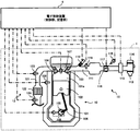
エンジン1は、図1に示すように、内燃部10と、内燃部10に連通した吸気部11と、同じく排気部12とで構成されている。
As shown in FIG. 1, the
内燃部10は、気筒101の内部の燃焼室101aにおいて混合気(霧状にした燃料と空気を混合したもの)が燃焼する際の圧力で上下に往復運動するピストン102と、燃焼室101aへの混合気の吸入口を開閉する吸気バルブ103と、混合気が燃焼した後の燃焼ガスを排出するために排出口を開閉する排気バルブ104と、ピストン102の往復運動を回転運動に変えるクランクシャフト105と、ピストン102とクランクシャフト105を接続するコネクティングロッド106と、燃焼室101aに吸入された混合気に着火するための点火プラグ107と、最適な空燃比(混合気における空気と燃料の混合比)を得ることができるよう燃料噴射時期を特定するためにクランクシャフト105の角度位置(クランク角)を検出するクランク角センサ108と、エンジン1の冷却水の温度を検出するサーミスタ等で構成された水温センサ109等を備えて構成されている。
The
吸気部11は、燃料を燃焼するために必要な燃料と空気とを内燃部10に送るためのもので、空気または燃料の通路となる吸気管111と、吸気バルブ103に燃料を噴射するための燃料噴射弁としてのインジェクタ112と、吸気口113から吸入する空気を浄化するエアフィルタ114と、吸入された空気の吸入量を検出するエアフロメータ115と、吸入する空気量を制御するスロットルバルブ116と、アクセル開度センサによって検出されたアクセルペダルの踏み込み量に基づいてスロットルバルブ116を駆動するスロットルバルブ駆動機構117と、スロットルバルブ駆動機構117によって駆動されたスロットルバルブ116の開度を検出するスロットル開度センサ118等を備えて構成されている。
The
排気部12は、内燃部10で燃焼されたガスを排気するためのもので、排気されたガスの通路となる排気管121と、三元触媒等で構成され排気されたガスを浄化する触媒122と、触媒122の上流側に設置され空燃比を検出するために酸素濃度に略比例した限界電流を出力する空燃比センサ123と、触媒122の下流側に設置され酸素濃度を検出する酸素センサ124等を備えて構成されている。
The
空燃比センサ123は、図2に示すように、排気管121の内部に向けて突設され、断面がコ字形状で、その周壁にカバー内外を連通する多数の小孔32が形成されたカバー30と、空燃比が燃料リーンを示す状態での酸素濃度、または空燃比が燃料リッチを示す状態でのCOやHC等の未燃ガス濃度に対応する限界電流を発生するセンサ本体34と、ヒータ36等を備えて構成されている。
As shown in FIG. 2, the air-
センサ本体34は、有底筒状の固体電解質層34aの外表面に排気ガス側電極層34bが固着され、内表面に大気側電極層34cが固着され、排気ガス側電極層34bの外側に拡散抵抗層34dがプラズマ溶射されている。
In the
固体電解質層34aは、ZrO2、HfO2 、ThO2 、Bi2O2等にCaO、MgO、Y2O3、Yb2O3 等の安定剤が配合された酸素イオン伝導性酸化物焼結体で構成され、拡散抵抗層34dは、アルミナ、マグネシャ、ケイ石質、スピネル、ムライト等の耐熱性無機物質で構成される。
The
排気ガス側電極層34b及び大気側電極層34cは共に、白金等の触媒活性の高い貴金属で構成され、その表面には多孔質の化学メッキ等が施されている。
Both the exhaust gas
ヒータ36は大気側電極層34cの内側に収容されており、その発熱によりセンサ本体34が加熱される。
The
センサ本体34は、空燃比が理論空燃比より燃料リーンを示す状態では酸素濃度に応じて、排気ガス側電極層34bの面積、拡散抵抗層34dの厚さ、気孔率及び平均孔径により決定される限界電流を発生する。また、空燃比が理論空燃比より燃料リッチを示す状態では、未燃ガスである一酸化炭素等の濃度が空燃比に対してほぼリニアに変化し、未燃ガス濃度に応じた限界電流を発生する。限界電流は、酸素濃度に対応した線形特性を示すが、約600℃以上の温度で活性化されるもので、ヒータ36による加熱でセンサ本体34が活性化温度域に制御される。
The sensor
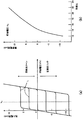
空燃比センサ123は、図3(a)に示すように、固体電解質層34aへの流入電流Iと印加電圧Vとが線形特性を有し、印加電圧軸に平行な直線部分Lが限界電流を表し、この限界電流の増減が空燃比の増減に対応している。つまり、図3(b)に示すように、空燃比が燃料リーンになる、つまり大きくなるほど限界電流は増大し、空燃比が燃料リッチになる、つまり小さくなるほど限界電流は減少する。
In the air-
電子制御装置4は、図4に示すように、CPU41と、CPU41で実行される制御プログラムが格納されたROM42及び/またはEEPROM43と、ワーキングエリアとして使用されるRAM44と、各種センサ等からのアナログ信号やデジタル信号を入力する入力インタフェース回路45と、入力された信号に基づいてCPU41で演算された結果としての信号を各種アクチュエータへ出力する出力インタフェース回路46等を備えて構成されている。
As shown in FIG. 4, the electronic control unit 4 includes a
電子制御装置4は、入力インタフェース回路45を介して、上述したクランク角センサ108、水温センサ109、エアフロメータ115、スロットル開度センサ118、及び空燃比センサ123等による検出値を入力し、CPU41が、これら検出値からエンジン1を制御する制御信号を算出する。例えば、クランク角センサ108の検出値等に基づいて燃料噴射タイミングやエンジン回転数を算出し、スロットル開度センサ118の検出値等に基づいてスロットル開度を算出する。そして、電子制御装置4は、出力インタフェース回路46を介して制御信号をインジェクタ112等へ出力することで、エンジン1の燃料噴射量等を制御する。
The electronic control unit 4 inputs detection values from the
また、電子制御装置4は、所定の走行条件が満たされた場合に内燃機関、つまりエンジン1の排気管121に設けられた空燃比センサ123の異常判定、つまり故障診断を行なう。
Further, the electronic control unit 4 performs abnormality determination, that is, failure diagnosis of the air-
所定の走行条件は、車両の状態検出部からの信号に基づいて車両の状態が安定していることである。つまり、後述する電子制御装置4の制御部は、後述する一連の処理を、車両の状態検出部からの信号に基づいて車両の状態が安定していることを判定する場合(つまり、所定の走行条件であることを判定する場合)に実行する。 The predetermined traveling condition is that the vehicle state is stable based on a signal from the vehicle state detection unit. That is, the control unit of the electronic control device 4 described later determines that the vehicle state is stable based on a signal from the vehicle state detection unit based on a signal from the vehicle state detection unit (that is, predetermined traveling). (When it is determined that the condition is satisfied).
所定の走行条件は、例えば、空燃比センサ123が活性状態に移行していること、エンジン回転数が所定回転数範囲に収まっていること、車速が所定速度範囲に収まっていること、燃料供給系で発生した蒸発燃料が吸気管111にパージされていないことが含まれる。ここで、車両の状態検出部は、空燃比センサ123やエンジン回転数を算出するためのクランク角を検出するクランク角センサ108等である。
The predetermined traveling conditions include, for example, that the air-
つまり、空燃比センサ123が活性状態に移行しているとともに、故障診断中に燃料噴射量の変動等が発生しない条件を満たすことが好ましい。後述するように、電子制御装置4は、燃料噴射量を変化させた際のステップ応答を計測することで、空燃比センサ123の故障診断を行なうため、ステップ応答の計測中は燃料噴射量を一定に維持する必要があり、ステップ応答の計測中に燃料噴射量が変化すると、故障診断を適正に実施できなくなるからである。
In other words, it is preferable that the air-
以下に詳述する。上述したように、空燃比センサ123等の酸素濃度センサの出力電圧は、一般に、温度依存性が高く、酸素濃度の検出精度を良好に維持するには素子温度を、所定の活性温度(例えば約600℃以上)に保つ必要がある。よって、所定の走行条件の一つを、空燃比センサ123が活性温度に保たれていることとすることで、電子制御装置4は空燃比センサ123の故障診断を適正に実施できる。
This will be described in detail below. As described above, the output voltage of an oxygen concentration sensor such as the air-
電子制御装置4は、エンジン回転数が変動すると当該変動に応じて燃料噴射量等を変動するように制御するので、排気管121内の空燃比が変動してしまい、電子制御装置4は空燃比センサ123の故障診断を適正に実施できなくなってしまう。よって、所定の走行条件の一つを、エンジン回転数が所定回転数範囲に収まっていることとすることで、電子制御装置4は空燃比センサ123の故障診断を適正に実施できる。同様に、車速が変動するとエンジン回転数が変動するので、車速が所定速度範囲に収まっていることも所定の走行条件の一つとすることで、電子制御装置4は空燃比センサ123の故障診断を適正に実施できる。
Since the electronic control unit 4 performs control so that the fuel injection amount or the like varies according to the fluctuation when the engine speed fluctuates, the air-fuel ratio in the
エンジン1の燃料を蓄積している燃料タンクには、燃料タンクからインジェクタ112へ送られたが内燃部10へ噴射されることなく燃料タンクへ送り戻されてきた高温の燃料等が原因で、燃料蒸気(燃料ベーパ)が発生することが知られている。
The fuel tank storing the fuel of the
燃料ベーパが発生すると燃料タンク内の圧力が上昇するので、溜まった燃料ベーパを外部に放出する必要があるが、燃料ベーパをそのまま外部に放出すると異臭を生じ、公害の原因となる虞がある。 When the fuel vapor is generated, the pressure in the fuel tank rises, so it is necessary to discharge the accumulated fuel vapor to the outside. However, if the fuel vapor is discharged to the outside as it is, a strange odor is generated, which may cause pollution.
そこで、燃料ベーパを捕集するためのキャニスタを吸気管111と連通して設けて、燃料ベーパを前記キャニスタに捕集しておき、エンジン駆動時に燃料ベーパを吸気管111へ送り燃料ベーパを燃焼させることで、燃料ベーパを外部に放出することなく燃料タンク内から除去する所謂パージが、車両において実行されている。
Therefore, a canister for collecting the fuel vapor is provided in communication with the
つまり、パージが実行されると吸気管111内に送られた燃料ベーパによって排気管121内の空燃比が変動してしまい、電子制御装置4は空燃比センサ123の故障診断を適正に実施できなくなってしまう。よって、所定の走行条件の一つを、燃料供給系で発生した蒸発燃料が吸気管111にパージされていないこととすることで、電子制御装置4は空燃比センサ123の故障診断を適正に実施できる。
That is, when the purge is executed, the air-fuel ratio in the
以下に、電子制御装置6による空燃比センサ123の故障診断について説明する。電子制御装置6は、空燃比センサ123が燃料リッチを示す状態で所定のリーン側空燃比に燃料噴射量を変化させた場合のリーン側ステップ応答、及び、空燃比センサ123が燃料リーンを示す状態で所定のリッチ側空燃比に燃料噴射量を変化させた場合のリッチ側ステップ応答を計測し、当該計測値から一次遅れ系のパラメータを夫々算出し、リーン側ステップ応答及びリッチ側ステップ応答夫々のパラメータの値に基づいて空燃比センサ123の故障診断を行なう制御部と、制御部による故障診断情報が記憶される記憶部を備えている。
Hereinafter, failure diagnosis of the air-
ここで、制御部はCPU41であり、上述の機能は、CPU41がROM42に記憶された制御プログラムを実行することで実現される。また、記憶部はRAM44及び/またはEEPROM43である。
Here, the control unit is the
リーン側ステップ応答の例を図5(a)に示し、リッチ側ステップ応答の例を図5(b)に示す。ステップ応答は、時刻に対する空燃比の特性であって、計算空燃比の瞬間的な変化に基づくステップ入力に対する実空燃比の応答特性である。 An example of the lean side step response is shown in FIG. 5A, and an example of the rich side step response is shown in FIG. The step response is a characteristic of the air-fuel ratio with respect to time, and is a response characteristic of the actual air-fuel ratio with respect to a step input based on an instantaneous change in the calculated air-fuel ratio.
制御部は、エアフロメータ115による検出値である空気量を、インジェクタ112への通電時間に基づいて算出される燃料量で除算することで計算空燃比を算出する。尚、制御部は、計算空燃比をエアフロメータ115の検出値に基づいて算出する代わりに、スロットルバルブの下流側に設置され、吸気管圧力を検出する吸気管圧力センサ119の検出値に基づいて空気量を算出することで、計算空燃比を算出してもよい。
The control unit calculates the calculated air-fuel ratio by dividing the air amount detected by the
また、制御部は、空燃比センサ123から入力された限界電流の値及び図3に示す特性に基づいて実空燃比を算出する。
Further, the control unit calculates the actual air-fuel ratio based on the limit current value input from the air-
制御部は、所定タイミングで、空燃比をリーン側空燃比(例えば、14.7)またはリッチ側空燃比(例えば、14.5)にするように燃料噴射量を急増または急減させる制御信号をインジェクタ112へ出力する。当該制御信号に対応する燃料噴射量に基づいて算出された計算空燃比の時刻に対する特性がステップ入力となる。 The control unit injects a control signal for rapidly increasing or decreasing the fuel injection amount so that the air-fuel ratio becomes a lean-side air-fuel ratio (for example, 14.7) or a rich-side air-fuel ratio (for example, 14.5) at a predetermined timing. To 112. A characteristic of the calculated air-fuel ratio calculated based on the fuel injection amount corresponding to the control signal with respect to time becomes a step input.
例えば、制御部は、図6(a)に示すように、リッチ側空燃比(14.5)の状態が所定時間tだけ継続したタイミングで、空燃比をリーン側空燃比(14.7)にするように燃料噴射量を変化させる制御信号をインジェクタ112へ出力する。すると、当該制御信号に対応する燃料噴射量によって排気管121内の空燃比である実空燃比がリッチ側空燃比(14.5)から理論空燃比(14.6)を介してリーン側空燃比(14.7)へ変化し、制御部は、空燃比センサ123から入力された当該変化を、リーン側ステップ応答として計測する。
For example, as shown in FIG. 6A, the control unit changes the air-fuel ratio to the lean-side air-fuel ratio (14.7) at the timing when the rich-side air-fuel ratio (14.5) continues for a predetermined time t. Then, a control signal for changing the fuel injection amount is output to the
同様に、制御部は、リーン側空燃比(14.7)の状態が所定時間tだけ継続したタイミングで、空燃比をリッチ側空燃比(14.5)にするように燃料噴射量を変化させる制御信号をインジェクタ112へ出力する。すると、当該制御信号に対応する燃料噴射量によって実空燃比がリーン側空燃比(14.7)から理論空燃比(14.6)を介してリッチ側空燃比(14.5)へ変化し、制御部は、空燃比センサ123から入力された当該変化を、リッチ側ステップ応答として計測する。
Similarly, the control unit changes the fuel injection amount so that the air-fuel ratio becomes the rich-side air-fuel ratio (14.5) at the timing when the state of the lean-side air-fuel ratio (14.7) continues for the predetermined time t. A control signal is output to the
つまり、図6(a)で空燃比が理論空燃比(14.6)より大きい部分が図5(a)(リーン側ステップ応答の例)に相当し、空燃比が理論空燃比(14.6)より小さい部分が図5(b)(リッチ側ステップ応答の例)に相当する。 That is, the portion in FIG. 6A where the air-fuel ratio is larger than the stoichiometric air-fuel ratio (14.6) corresponds to FIG. 5A (an example of lean side step response), and the air-fuel ratio is the stoichiometric air-fuel ratio (14.6). The smaller part corresponds to FIG. 5B (example of rich side step response).
尚、所定タイミングは、リッチ側またはリーン側空燃比の状態が所定時間tだけ継続したタイミングに限らず、例えば、空燃比が理論空燃比となったタイミング等であってもよい。 The predetermined timing is not limited to the timing at which the rich-side or lean-side air-fuel ratio state continues for the predetermined time t, and may be, for example, the timing at which the air-fuel ratio becomes the stoichiometric air-fuel ratio.
制御部は、ステップ入力とステップ応答から所定のパラメータを算出する。パラメータには無駄時間、時定数、ゲインが含まれ、制御部は各パラメータの値が所定の許容範囲に収まるか否かに基づいて空燃比センサ123の故障診断を行なう。
The control unit calculates a predetermined parameter from the step input and the step response. The parameters include dead time, time constant, and gain, and the control unit performs failure diagnosis of the air-
尚、制御部は、各パラメータの差分値が所定の許容範囲に収まるか否かに基づいて空燃比センサ123の故障診断を行なうが、これについては後述する。また、以下の説明では、図5(a)に示すリーン側ステップ応答に基づいて説明するが、図5(b)に示すリッチ側ステップ応答の場合もリーン側ステップ応答の場合と同様である。
The control unit performs failure diagnosis of the air-
以上の説明より、ステップ応答とは、所定時間当たりの空燃比センサ123の出力値が変化する状態を言う。
From the above description, the step response refers to a state in which the output value of the air-
無駄時間Dは、ステップ入力がリッチ側空燃比へ変化した瞬間から、当該変化に対応してステップ応答がリーン側空燃比から理論空燃比へ変化する瞬間までの時間である。 The dead time D is the time from the moment when the step input changes to the rich air-fuel ratio to the moment when the step response changes from the lean air-fuel ratio to the stoichiometric air-fuel ratio corresponding to the change.
時定数Tは、ステップ応答がリーン側空燃比から理論空燃比へ変化した瞬間T1から、当該瞬間T1以後(ステップ応答の立ち上がり以後)で最大の傾斜が、当該傾斜のままステップ応答の収束値に達したと仮定した時刻T2までの時間である。 The time constant T is the convergence of the step response from the instant T1 when the step response has changed from the lean air-fuel ratio to the stoichiometric air-fuel ratio, after the instant T1 (after the rise of the step response). This is the time until time T2 that is assumed to have been reached.
尚、当該傾斜は、制御部によって以下のように算出される。空燃比センサ123の出力特性は、燃料リーン状態から燃料リッチ状態、燃料リッチ状態から燃料リーン状態へ変化した後、初期の一定時間における空燃比センサ123の出力値の変化が比例となることが統計的にわかっている。その比例を示す初期の一定時間における空燃比センサ123の出力値の変化に基づき傾斜が算出される。
The inclination is calculated by the control unit as follows. The output characteristic of the air-
また、収束値とは、ステップ応答が収束する値を予め試験等により得たものである。 The convergence value is a value obtained by preliminarily obtaining a value at which the step response converges.
ゲインKは、ステップ応答の収束値(図5(a)の「b」)からステップ入力値(図5(a)の「a」)を除算した値である。 The gain K is a value obtained by dividing the step input convergence value (“a” in FIG. 5A) from the convergence value of the step response (“b” in FIG. 5A).
上述の構成によれば、制御部は、所定のパラメータに基づいて空燃比センサ123の故障診断を行なうので、ステップ応答の立ち上がり特性を一定時間毎に測定する等の煩雑な測定を行なうことなく、空燃比センサ123の故障診断を適切に行なうことができる。
According to the above-described configuration, the control unit performs failure diagnosis of the air-
そして、制御部は、無駄時間Dが所定範囲内であるか否か、時定数Tが所定範囲内であるか否か、ゲインKが所定範囲内であるか否かで故障診断する。例えば、制御部は、無駄時間Dが所定時間(例えば4(msec))以上の場合に空燃比センサ123の無駄時間異常であると診断し、時定数Tが所定範囲(例えば0.1〜0.4(msec))外の場合に空燃比センサ123の応答性低下異常であると診断し、ゲインKが所定値(例えば1.2)以上である場合に空燃比センサ123の出力拡大異常であると診断し、ゲインKが所定値(例えば0.8)以下である場合に空燃比センサ123の出力縮小異常であると診断する。
Then, the control unit performs a failure diagnosis based on whether the dead time D is within a predetermined range, whether the time constant T is within the predetermined range, and whether the gain K is within the predetermined range. For example, the control unit diagnoses that the dead time of the air-
尚、無駄時間異常及び応答性低下異常の診断は、リッチ側ステップ応答とリーン側ステップ応答の夫々で個別に実行し、出力拡大異常及び出力縮小異常の診断は、リッチ側ステップ応答とリーン側ステップ応答の平均値に基づいて実行するが、これに限らない。例えば、無駄時間異常及び応答性低下異常の診断をリッチ側ステップ応答とリーン側ステップ応答の平均値に基づいて実行してもよいし、出力拡大異常及び出力縮小異常の診断をリッチ側ステップ応答とリーン側ステップ応答の夫々で個別に実行してもよい。 In addition, the diagnosis of the dead time abnormality and the responsiveness decrease abnormality is executed separately for each of the rich side step response and the lean side step response, and the diagnosis of the output side expansion response and the output side reduction response is performed separately for the rich side step response and the lean side step. Although it performs based on the average value of a response, it is not restricted to this. For example, the diagnosis of the dead time abnormality and the responsiveness deterioration abnormality may be executed based on the average value of the rich side step response and the lean side step response, and the diagnosis of the output expansion abnormality and the output reduction abnormality is made as the rich side step response. Each of the lean side step responses may be executed individually.
以上説明した制御部による診断結果(無駄時間異常、応答性低下異常、出力拡大異常、及び出力縮小異常の有無、並びに、これら異常の発生時刻等)は、故障診断情報として、記憶部に記憶される。 The diagnosis results by the control unit described above (absence of dead time abnormality, responsiveness deterioration abnormality, output expansion abnormality, output reduction abnormality, and the occurrence time of these abnormalities, etc.) are stored in the storage unit as failure diagnosis information. The
上述の構成によれば、制御部は、リーン側ステップ応答及びリッチ側ステップ応答夫々のパラメータに基づいて空燃比センサの故障診断を行なうことで、空燃比のリッチ側空燃比からリーン側空燃比への変動の際の空燃比センサ123の異常、及び、空燃比のリーン側空燃比からリッチ側空燃比への変動の際の空燃比センサ123の異常を、別々の異常として検知することができる。
According to the above-described configuration, the control unit performs failure diagnosis of the air-fuel ratio sensor based on the parameters of the lean-side step response and the rich-side step response, thereby changing the air-fuel ratio from the rich-side air-fuel ratio to the lean-side air-fuel ratio. The abnormality of the air-
また、制御部は、リーン側ステップ応答及びリッチ側ステップ応答夫々のパラメータの差分値に基づいて空燃比センサ123の故障診断を行ない、記憶部には、制御部による故障診断情報が記憶される。
Further, the control unit performs a failure diagnosis of the air-
パラメータの差分値に基づいて空燃比センサ123の故障診断を行なう場合であっても、上述同様、パラメータには上述した無駄時間D、時定数T、ゲインKが含まれる。
Even when the failure diagnosis of the air-
そして、制御部は対応するパラメータ毎の差分値が所定の許容範囲に収まるか否かに基づいて空燃比センサ123の故障診断を行なう。
Then, the control unit performs failure diagnosis of the air-
つまり、リーン側ステップ応答における無駄時間Dとリッチ側ステップ応答における無駄時間Dの差分の絶対値が所定値以上である場合に空燃比センサ123の無駄時間非対称異常であると診断し、リーン側ステップ応答における時定数Tとリッチ側ステップ応答における時定数Tの差分の絶対値が所定値以上である場合に空燃比センサ123の応答性非対称異常であると診断し、リーン側ステップ応答におけるゲインKとリッチ側ステップ応答におけるゲインKの差分の絶対値が所定値以上である場合に空燃比センサ123のゲイン非対称異常であると診断する。
That is, if the absolute value of the difference between the dead time D in the lean side step response and the dead time D in the rich side step response is equal to or greater than a predetermined value, the air-
以上説明した制御部による診断結果(無駄時間非対称異常、応答性非対称異常、及びゲイン非対称異常の有無、並びに、これら異常の発生時刻等)も、上述した診断結果と同様に、故障診断情報として、記憶部に記憶される。 The diagnosis results by the control unit described above (the presence / absence of dead time asymmetric abnormality, responsive asymmetry abnormality, gain asymmetry abnormality, and the occurrence time of these abnormalities, etc.) are also provided as failure diagnosis information, similar to the above-described diagnosis results. Stored in the storage unit.
制御部は、以上説明したうちの少なくとも一つの異常があると空燃比センサ123の故障であると判断する。
The control unit determines that the air-
つまり、制御部は、リーン側ステップ応答及びリッチ側ステップ応答夫々のパラメータが所定の許容範囲に収まる場合(無駄時間異常、応答性低下異常、出力拡大異常、及び出力縮小異常の何れも発生していない場合)であっても、対応するパラメータ毎の差分値が所定の許容範囲を逸脱する場合(無駄時間非対称異常、応答性非対称異常、及びゲイン非対称異常の何れかが発生している場合)には、空燃比センサ123が故障していると診断する。
In other words, the control unit, when the parameters of the lean side step response and the rich side step response fall within the predetermined allowable range (all of the dead time abnormality, the responsiveness reduction abnormality, the output expansion abnormality, and the output reduction abnormality have occurred). Even when the difference value for each corresponding parameter deviates from the predetermined allowable range (when any of the dead time asymmetry abnormality, responsiveness asymmetry abnormality, or gain asymmetry abnormality occurs). Diagnoses that the air-
上述の構成によれば、制御部は、リーン側ステップ応答またはリッチ側ステップ応答のみに基づく測定では正常であると判定されてしまう空燃比センサ123の異常を診断することができるので、空燃比センサ123の異常をより確実に検出することができる。
According to the above configuration, the control unit can diagnose an abnormality of the air-
制御部は、一回の故障診断時にリーン側ステップ応答及びリッチ側ステップ応答の計測を交互に複数回(例えば5回)繰り返し、夫々で算出されたパラメータの平均値に基づいて故障診断を行なってもよい。 The controller repeats the measurement of the lean side step response and the rich side step response a plurality of times (for example, 5 times) alternately at the time of one failure diagnosis, and performs the failure diagnosis based on the average value of the parameters calculated respectively. Also good.
以下に詳述する。制御部は、上述した所定の走行条件が満たされると、燃料噴射量の急増と急減を交互に繰り返すような制御信号をステップ入力としてインジェクタ112へ出力する。例えば、制御部は、図6(a)に示すような同一波形が所定回数(例えば5回)だけ繰り返されるパルス信号をインジェクタ112へ出力する。
This will be described in detail below. When the predetermined traveling condition described above is satisfied, the control unit outputs a control signal that alternately repeats rapid increase and decrease of the fuel injection amount to the
制御部は、当該制御信号のパルス値の変化(リッチ側空燃比からリーン側空燃比への変化、及び、リーン側空燃比からリッチ側空燃比への変化)の度に、当該変化に伴うリーン側ステップ応答とリッチ側ステップ応答を計測する。 Each time the control unit changes the pulse value of the control signal (change from the rich air-fuel ratio to the lean air-fuel ratio and change from the lean air-fuel ratio to the rich air-fuel ratio), Side step response and rich side step response are measured.
制御部は、所定回数のパルス信号の各回で測定されたステップ応答に基づいて算出された各パラメータの合計値を所定回数で除算することによって、各パラメータの平均値を算出する。例えば、5回の測定で算出された無駄時間をD1、D2、D3、D4、D5とした場合、無駄時間の平均値は、(D1+D2+D3+D4+D5)/5で算出される。 The control unit calculates the average value of each parameter by dividing the total value of each parameter calculated based on the step response measured each time of the predetermined number of pulse signals by the predetermined number of times. For example, when the dead times calculated in five measurements are D1, D2, D3, D4, and D5, the average value of the dead times is calculated as (D1 + D2 + D3 + D4 + D5) / 5.
制御部は、算出した各パラメータの平均値及び当該平均値のパラメータ毎の差分が所定の許容範囲に収まるか否かに基づいて、空燃比センサ123の故障診断を行なう。
The control unit performs failure diagnosis of the air-
上述の構成によれば、制御部は、パラメータを複数回算出してその平均値に基づいて故障診断を行なうので、複数回算出したパラメータの一部がノイズ等の影響によって誤差を伴った場合でも、空燃比センサ123の故障診断を適正に行なうことができる。
According to the above-described configuration, the control unit calculates the parameter a plurality of times and performs failure diagnosis based on the average value. Therefore, even when some of the parameters calculated a plurality of times are accompanied by an error due to the influence of noise or the like. Thus, failure diagnosis of the air-
制御部は故障診断の結果、空燃比センサ123が正常であるか故障しているかを識別するデータ、及び、モニタ頻度を記憶部に記憶する。
As a result of the failure diagnosis, the control unit stores data for identifying whether the air-
換言すると、制御部は異常判定処理の実行により、空燃比センサ123が正常であるか異常であるかを識別するデータ、またはモニタ頻度を記憶部に記憶する。
In other words, the control unit stores the data for identifying whether the air-
空燃比センサ123が正常であるか故障しているかを識別するデータは、上述した故障診断情報のうちの各種異常の有無を示す情報である。
Data identifying whether the air-
モニタ頻度は、所定の走行条件が満たされた場合に計数される走行回数(IG−ONからIG−OFFまでの1トリップを一走行とする。)と、その場合に行なわれる故障診断により正常または異常と判定された場合に計数されるモニタリング回数の比であり、例えばモニタリング回数を走行回数で除算した値で表わされる。 The monitoring frequency is normal based on the number of times counted when a predetermined driving condition is satisfied (one trip from IG-ON to IG-OFF is one driving) and a failure diagnosis performed in that case. This is the ratio of the number of monitoring times counted when it is determined as abnormal, and is represented by, for example, a value obtained by dividing the number of monitoring times by the number of traveling times.
走行回数は、所定の走行条件が満たされた場合にインクリメントされ、モニタリング回数は、電子制御装置4による故障診断の結果、空燃比センサ123の正常または異常の判定が終了した時点でインクリメントされる。つまり、故障診断の結果、正常とも異常とも判別できなかった場合、モニタリング回数はそのままの値が維持される。
The number of times of travel is incremented when a predetermined travel condition is satisfied, and the number of times of monitoring is incremented when determination of normality or abnormality of the air-
OBD2のRateBaseモニタ法では、サービス09のIPT(In−use Performance Tracking)に関連して、モニタ頻度を継続的に記憶する必要があるが、上述の構成によれば、電子制御装置4は、この法規の規定を遵守することができる。 In the RateBase monitoring method of OBD2, it is necessary to continuously store the monitoring frequency in relation to the IPT (In-use Performance Tracking) of the service 09. According to the above configuration, the electronic control unit 4 You can comply with the provisions of the law.
制御部は、パラメータの算出値が診断不能値を示す場合に、診断実施回数に対する診断不能回数の累積比率を記憶部に記憶するとともに、当該累積比率が所定比率を超えるまで再度故障診断を行なう。 When the calculated value of the parameter indicates a value that cannot be diagnosed, the control unit stores the cumulative ratio of the number of times of diagnosis impossible with respect to the number of times of diagnosis in the storage unit and performs fault diagnosis again until the cumulative ratio exceeds a predetermined ratio.
以下に詳述する。診断不能値は、各パラメータが現実には取り得ない値であり、例えば、マイナス値、パルス信号の周期より大きい無駄時間Dや時定数Tの値等である。 This will be described in detail below. The undiagnosable value is a value that each parameter cannot actually take, and is, for example, a negative value, a dead time D greater than the period of the pulse signal, a value of the time constant T, or the like.
診断実施回数は、故障診断が実施された回数である。ここで、本実施形態では、制御部は所定の走行条件が満たされた場合に故障診断を行なうことから、診断実施回数は上述した走行回数と同値となる。しかし、制御部が所定の走行条件が満たされても必ずしも故障診断を行なわない場合、診断実施回数と走行回数は異なる値となることがある。 The number of times of diagnosis execution is the number of times that failure diagnosis has been performed. Here, in the present embodiment, since the control unit performs a failure diagnosis when a predetermined traveling condition is satisfied, the number of times of diagnosis is equal to the number of times of traveling described above. However, if the control unit does not always perform a failure diagnosis even if a predetermined traveling condition is satisfied, the number of times of diagnosis and the number of traveling may be different values.
診断不能回数は、制御部による故障診断ができない場合に計数される。具体的には、制御部によって算出された各パラメータの少なくとも一つが診断不能値である場合に、インクリメントされる。 The number of undiagnosable times is counted when failure diagnosis by the control unit is not possible. Specifically, the value is incremented when at least one of the parameters calculated by the control unit is an undiagnosable value.
累積比率は、診断不能回数と診断実施回数の比であり、例えば診断不能回数を診断実施回数で除算した値で表わされる。 The cumulative ratio is a ratio between the number of times of diagnosis impossible and the number of times of diagnosis, and is represented by a value obtained by dividing the number of times of diagnosis impossible by the number of times of diagnosis.
上述の構成によれば、制御部は、パラメータの算出値を診断不能値と比較することによって、電子制御装置4による空燃比センサ123やエアフロメータ115等からのデータの取得の失敗や、制御部での計算空燃比及び実空燃比の算出の失敗を検出することができる。また、制御部は、パラメータの算出値が診断不能値を示す場合であっても、診断不能回数の累積比率が所定比率を超えるまで再度故障診断を行なうので、ノイズ等の影響によってパラメータの算出値に異常が生じても、それによって空燃比センサ123が即異常と診断されてしまうことを防止することができる。
According to the above-described configuration, the control unit compares the calculated value of the parameter with the undiagnosable value, thereby causing the electronic control device 4 to fail in acquiring data from the air-
制御部は、故障診断をエンジン始動から停止までの間に少なくとも一回行なうように構成され、故障診断が所定回数連続して正常に終了すると記憶部に記憶された累積比率をリセットする。 The control unit is configured to perform the failure diagnosis at least once from the engine start to the stop, and resets the cumulative ratio stored in the storage unit when the failure diagnosis is normally completed a predetermined number of times.
例えば、制御部は、エンジン始動から停止までの間に、最初に所定の走行条件が満たされた場合、所定の走行条件が満たされる度、或は、予め設定された所定回数を限度として所定の走行条件が満たされる度等に、故障診断を行なう。尚、制御部は、エンジン始動から停止までの間に、所定の走行条件が満たされることがなかった場合、故障診断を実施しない。 For example, when a predetermined traveling condition is initially satisfied between the engine start and the stop, the control unit performs a predetermined time every time the predetermined traveling condition is satisfied or a predetermined number of times set in advance. A fault diagnosis is performed every time driving conditions are satisfied. Note that the control unit does not perform a failure diagnosis when a predetermined traveling condition is not satisfied between the engine start and the stop.
また、制御部は、故障診断が正常に終了する度(例えば、算出されたパラメータが診断不能値でない場合)にインクリメントし、故障診断が正常に終了しない場合にリセットする診断正常終了回数を設定しておき、当該診断正常終了回数が所定回数(例えば20回)以上となった場合に、診断不能回数及び診断実施回数をリセットすることで累積比率をリセットする。 In addition, the control unit increments each time the failure diagnosis ends normally (for example, when the calculated parameter is not an undiagnosable value), and sets the number of times that the diagnosis ends normally when the failure diagnosis does not end normally. In addition, when the number of normal diagnosis ends is equal to or greater than a predetermined number (for example, 20 times), the cumulative ratio is reset by resetting the number of times diagnosis is impossible and the number of times diagnosis is performed.
上述の構成によれば、制御部による故障診断で、過去にはパラメータの算出値が診断不能値を示すこと(以下、算出失敗と記す。)が多かったが、現在ではパラメータの算出値が診断不能値を示すことが殆どない場合に、新たにパラメータの算出値が診断不能値を示した場合、過去の算出失敗の影響を受けて、累積比率が所定比率を直ぐに超えてしまうことを防止することができる。 According to the above-described configuration, in the past, in the failure diagnosis by the control unit, the calculated value of the parameter often indicated an undiagnosable value (hereinafter referred to as “calculation failure”), but now the calculated value of the parameter is diagnosed. When the calculated value of the parameter newly indicates an undiagnosable value when there is hardly any impossible value, the cumulative ratio is prevented from immediately exceeding the predetermined ratio due to the influence of the past calculation failure. be able to.
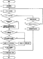
以下、電子制御装置4の制御部による空燃比センサ123の故障診断について、図7に示すフローチャートに基づいて説明する。
Hereinafter, failure diagnosis of the air-
所定の走行条件が満たされ、空燃比センサ123の故障診断が開始されると、走行回数(及び診断実施回数)がインクリメントされる(S1)。
When a predetermined traveling condition is satisfied and failure diagnosis of the air-
制御部は、燃料噴射量の急増と急減を交互に繰り返すようなステップ入力として、同一波形が所定回数だけ繰り返されるパルス信号をインジェクタ112へ出力する。そして、当該パルス信号の各回でリーン側ステップ応答及びリッチ側ステップ応答を計測し、当該計測値から一次遅れ系のパラメータ(無駄時間D、時定数T、及びゲインK)を算出する。最後に、各パラメータの合計値を所定回数で除算することによって、各パラメータの平均値を算出する(S2)。
The control unit outputs a pulse signal, which repeats the same waveform a predetermined number of times, to the
算出したパラメータ(またはパラメータの平均値)が診断不能値を示す場合(S3)、制御部は、診断不能回数をインクリメントして、現在の診断実施回数及び診断不能回数に基づいて累積比率を算出し、算出した累積比率を記憶部に記憶する(S4)。 When the calculated parameter (or the average value of the parameters) indicates an undiagnosable value (S3), the control unit increments the undiagnosable number and calculates a cumulative ratio based on the current number of diagnoses and undiagnosable times. The calculated cumulative ratio is stored in the storage unit (S4).
制御部は、累積比率が予め設定された所定比率以上の場合(S5)、故障診断不能と判定し(S6)、累積比率が所定比率より小さい場合(S5)、再び各パラメータの平均値を算出する(S2)。つまり、累積比率が所定比率以上となるまで、または、算出したパラメータが診断不能値を示さなくなるまで、各パラメータの平均値の算出が試みられる。 When the cumulative ratio is greater than or equal to a predetermined ratio set in advance (S5), it is determined that failure diagnosis is impossible (S6). When the cumulative ratio is smaller than the predetermined ratio (S5), the average value of each parameter is calculated again. (S2). That is, the calculation of the average value of each parameter is attempted until the cumulative ratio is equal to or greater than the predetermined ratio, or until the calculated parameter does not indicate a diagnosis impossible value.
算出したパラメータが診断不能値を示さない場合(S3)、制御部は、診断正常終了回数をインクリメントして、当該診断正常終了回数が所定回数以上である場合(S7)、診断実施回数、診断不能回数、及び累積比率をリセットする(S8)。 When the calculated parameter does not indicate an undiagnosable value (S3), the control unit increments the number of normal diagnosis ends, and when the number of normal diagnosis ends is equal to or greater than a predetermined number (S7), the number of times of diagnosis execution, undiagnosable The number of times and the cumulative ratio are reset (S8).
制御部は、ステップS2で算出したパラメータ(またはパラメータの平均値)が所定の許容範囲に収まり(S9)、且つ、当該パラメータ毎(または当該パラメータの平均値毎)の差分値が所定の許容範囲に収まる場合(S10)、空燃比センサ123は正常であると診断する(S11)。一方、ステップS9、S10の何れかで所定の許容範囲に収まらない場合、空燃比センサ123は故障していると診断する(S12)。尚、制御部は、これらの診断結果(正常または故障の結果)を記憶部に記憶する。
The control unit determines that the parameter (or parameter average value) calculated in step S2 falls within a predetermined allowable range (S9), and the difference value for each parameter (or each parameter average value) is a predetermined allowable range. (S10), the air-
その後、制御部はモニタリング回数をインクリメントし(S13)、現在の走行回数とモニタリング回数に基づいてモニタ頻度を算出して、算出したモニタ頻度を記憶部に記憶する(S14)。 Thereafter, the control unit increments the number of monitoring (S13), calculates a monitoring frequency based on the current number of running times and the number of monitoring, and stores the calculated monitoring frequency in the storage unit (S14).
以上説明したとおり、本発明による故障診断方法は、所定の走行条件が満たされた場合に実行される内燃機関1の排気管121に設けられた空燃比センサ123の故障診断方法であって、空燃比センサ123が燃料リッチを示す状態で所定のリーン側空燃比に燃料噴射量を変化させた場合のリーン側ステップ応答、及び、空燃比センサ123が燃料リーンを示す状態で所定のリッチ側空燃比に燃料噴射量を変化させた場合のリッチ側ステップ応答を計測し、当該計測値から一次遅れ系のパラメータを夫々算出し、リーン側ステップ応答及びリッチ側ステップ応答夫々のパラメータの差分値に基づいて空燃比センサ123の故障診断を行なう方法である。
As described above, the failure diagnosis method according to the present invention is a failure diagnosis method for the air-
以下、別実施形態について説明する。上述の実施形態では、制御部は、ステップ応答の計測を、図6(a)において破線で示すようにリーン側ステップ応答とリッチ側ステップ応答を交互に計測する場合について説明したが、制御部は、図6(b)において破線で示すように夫々のステップ応答を連続して計測してもよいし、図6(c)において破線で示すように夫々のステップ応答を離散して計測(例えば、所定数おきに計測)してもよい。尚、図6(b)はリーン側ステップ応答を連続して計測する場合を示しており、図6(c)はリーン側ステップ応答を一回おきに計測する場合を示している。 Hereinafter, another embodiment will be described. In the above-described embodiment, the control unit has described the case where the measurement of the step response is alternately measured as the lean side step response and the rich side step response as indicated by the broken line in FIG. 6B, each step response may be continuously measured as indicated by a broken line in FIG. 6B, or each step response is discretely measured as indicated by a broken line in FIG. 6C (for example, (Measured every predetermined number). FIG. 6B shows a case where the lean side step response is continuously measured, and FIG. 6C shows a case where the lean side step response is measured every other time.
上述の実施形態では、制御部は累積比率を記憶部に記憶するとともに、当該累積比率が所定比率を超えると故障診断不能と判定する場合について説明したが、故障診断不能の判定は累積比率に基づいて行なう場合に限らない。例えば、制御部は、パラメータの算出値が予め設定された所定回数以上連続して診断不能値を示した場合に、故障診断不能と判定してもよい。 In the above-described embodiment, the control unit stores the cumulative ratio in the storage unit, and the case where it is determined that failure diagnosis is impossible when the cumulative ratio exceeds a predetermined ratio has been described. This is not necessarily the case. For example, the control unit may determine that failure diagnosis is impossible when the calculated value of the parameter continuously indicates a diagnosis impossible value for a predetermined number of times or more.
上述の実施形態では、制御部は、一回の故障診断時にリーン側ステップ応答及びリッチ側ステップ応答の計測を交互に所定回数(例えば5回)繰り返し、夫々で算出されたパラメータの平均値に基づいて故障診断を行なう場合について説明した。 In the above-described embodiment, the control unit alternately repeats the measurement of the lean side step response and the rich side step response a predetermined number of times (for example, 5 times) at the time of one failure diagnosis, and is based on the average value of the parameters calculated respectively. The case where failure diagnosis is performed has been described.
この場合、所定回数のうちの少なくとも1回で、パラメータの算出値が診断不能値を示すこと等によって、適正にパラメータを算出できなかった場合、制御部は、パラメータの算出は失敗したと判定して診断不能回数をインクリメントする構成であってもよいし、適正に算出できたパラメータのみの平均で故障診断を実施する構成であってもよい。 In this case, the control unit determines that the parameter calculation has failed when the parameter calculation value cannot be properly calculated at least once of the predetermined number of times because the parameter calculation value indicates an undiagnosable value. In other words, the configuration may be such that the number of times the diagnosis cannot be performed is incremented, or the failure diagnosis is performed with an average of only parameters that can be appropriately calculated.
上述の実施形態では、制御部は、故障診断情報、モニタ頻度、及び累積比率等を記憶部としてのRAM44及び/またはEEPROM43に記憶する場合について説明したが、制御部は、故障診断情報、モニタ頻度、及び累積比率等を算出した時点で一旦RAM44に記憶しておき、エンジン停止の際等にRAM44からEEPROM43に転送してもよい。これによって、データの書込み及び読出し速度が一般にRAM44に比べて遅いEEPROM43の使用を最小限に抑えることができる。
In the above-described embodiment, the control unit has described the case where the failure diagnosis information, the monitoring frequency, the cumulative ratio, and the like are stored in the
上述の実施形態では、制御部が、リーン側ステップ応答及びリッチ側ステップ応答に基づいて算出された一次遅れ系のパラメータに基づいて、空燃比センサ123の故障診断(異常判定)を行なう場合について説明したが、一次遅れ系のパラメータ以外に基づいて異常判定を行なってもよい。
In the above-described embodiment, a case where the control unit performs failure diagnosis (abnormality determination) of the air-
以下に一例について詳述する。例えば、制御部は、空燃比センサ123からの信号に基づいて、燃料リッチ状態から燃料リーン状態に移行した瞬間から、再び燃料リーン状態から燃料リッチ状態へ移行する瞬間までの時間t1を算出するとともに、燃料リーン状態から燃料リッチ状態に移行した瞬間から、再び燃料リッチ状態から燃料リーン状態へ移行する瞬間までの時間t2を算出する。
An example will be described in detail below. For example, based on the signal from the air-
また、制御部は、燃料噴射部としてのインジェクタ112から噴射された燃料量と、吸気量検出部としてのエアフロメータ115からの信号により算出される吸気量に基づいて、燃料リーン状態への変化値としての時間t1に対応する推定時間t1´を推定するとともに、燃料リッチ状態への変化値としての時間t2に対応する推定時間t2´を推定する。
Further, the control unit changes the fuel lean state based on the amount of fuel injected from the
また、制御部は、時間t1と時間t1´の差分(t1−t1´)、及び、時間t2と時間t2´の差分(t2−t2´)を算出するとともに、各差分(t1−t1´)、(t2−t2´)の絶対値の差分tを算出する。 In addition, the control unit calculates a difference (t1−t1 ′) between the time t1 and the time t1 ′ and a difference (t2−t2 ′) between the time t2 and the time t2 ′ and each difference (t1−t1 ′). , (T2−t2 ′) absolute value difference t is calculated.
そして、制御部は、差分tが予め設定された異常判定閾値以上の場合に、空燃比センサ123が異常であると推定する。尚、各差分(t1−t1´)、(t2−t2´)が、夫々について予め設定された異常判定閾値以上の場合に、空燃比センサ123が異常であると推定してもよい。
Then, the control unit estimates that the air-
以上の説明より、本発明による電子制御装置4は、一次遅れ系のパラメータに基づいて空燃比センサ123の異常判定を行なうか否かにかかわらず、以下に示す処理を実行する。
From the above description, the electronic control unit 4 according to the present invention executes the following processing regardless of whether or not the abnormality determination of the air-
つまり、電子制御装置4は、内燃機関1の排気管121に設けられた空燃比センサ123の異常判定を行う電子制御装置4であって、空燃比センサ123の異常を判定するための異常判定閾値を記憶する記憶部と、以下に示す五種類の処理(燃料リーン判定検出処理、燃料リッチ反転検出処理、燃料リーン変化値差分算出処理、燃料リッチ変化値差分算出処理、及び空燃比センサ異常判定処理)を実行する制御部を備えている。
That is, the electronic control unit 4 is an electronic control unit 4 that performs an abnormality determination of the air-
燃料リーン反転検出処理は、内燃機関1を制御する際に、空燃比センサ123からの信号により判定する空燃比が燃料リッチを示す状態から、燃料リーンを示す状態へ変化するのを検出する処理である。
The fuel lean reversal detection process is a process for detecting a change in the air-fuel ratio determined by the signal from the air-
燃料リッチ反転検出処理は、内燃機関1を制御する際に、空燃比センサ123からの信号により判定する空燃比が燃料リーンを示す状態から、燃料リッチを示す状態へ変化するのを検出する処理である。
The fuel-rich inversion detection process is a process for detecting when the air-fuel ratio determined by a signal from the air-
燃料リーン変化値差分算出処理は、燃料リーン反転検出処理の実行により燃料リッチ状態から燃料リーン状態への変化を検出した場合に、燃料噴射部112により噴射した燃料量と、吸気量検出部115からの信号により判定する吸気量に基づいて推定した燃料リーン状態への変化値と、空燃比センサ123からの信号により判定する燃料リーン状態への変化値との差分を算出する処理である。
The fuel lean change value difference calculation process is performed by the fuel amount injected by the
燃料リッチ変化値差分算出処理は、燃料リッチ反転検出処理の実行により燃料リーン状態から燃料リッチ状態への変化を検出した場合に、燃料噴射部112により噴射した燃料量と、吸気量検出部115からの信号により判定する吸気量に基づいて推定した燃料リッチ状態への変化値と、空燃比センサ123からの信号により判定する燃料リッチ状態への変化値との差分を算出する処理である。
In the fuel rich change value difference calculation process, when the change from the fuel lean state to the fuel rich state is detected by executing the fuel rich inversion detection process, the fuel amount injected by the
空燃比センサ異常判定処理は、燃料リーン変化値差分算出処理の実行により算出される差分の絶対値と、燃料リッチ変化値差分算出処理の実行により算出される差分の絶対値との差分が、記憶部が記憶する異常判定閾値以上の場合に、空燃比センサ123が異常であると判定する処理である。
The air-fuel ratio sensor abnormality determination process stores the difference between the absolute value of the difference calculated by executing the fuel lean change value difference calculation process and the absolute value of the difference calculated by executing the fuel rich change value difference calculation process. This is a process for determining that the air-
ここで、上述の実施形態のように、電子制御装置4が一次遅れ系のパラメータに基づいて空燃比センサ123の異常判定を行なう場合、燃料リッチ及び燃料リーンへの変化値は、以下に示すとおりである。
Here, as in the above-described embodiment, when the electronic control unit 4 performs abnormality determination of the air-
つまり、制御部が実行する異常判定処理における、空燃比センサ123からの信号により判定する燃料リッチ及び燃料リーンへの変化値は、燃料噴射部112により噴射した燃料量と、吸気量検出部115からの信号により判定する吸気量に基づいて推定した燃料リッチ及び燃料リーンへの変化値との関係において、一次遅れを示すパラメータであり、パラメータは無駄時間、時定数、またはゲインを含む。
That is, in the abnormality determination process executed by the control unit, the change values to the fuel rich and the fuel lean determined by the signal from the air-
以上説明したとおり、本発明による内燃機関1の排気管121に設けられた空燃比センサ123の異常判定を行う制御方法は、以下に示す五つのステップ(燃料リーン反転検出ステップ、燃料リッチ反転検出ステップ、燃料リーン変化値差分算出ステップ、燃料リッチ変化値差分算出ステップ、及び空燃比センサ異常判定ステップ)を実行する方法である。
As described above, the control method for determining the abnormality of the air-
燃料リーン反転検出ステップは、内燃機関1を制御する際に、空燃比センサ123からの信号により判定する空燃比が燃料リッチを示す状態から、燃料リーンを示す状態へ変化するのを検出するステップである。
The fuel lean inversion detection step is a step of detecting a change in the air-fuel ratio determined by the signal from the air-
燃料リッチ反転検出ステップは、内燃機関1を制御する際に、空燃比センサ123からの信号により判定する空燃比が燃料リーンを示す状態から、燃料リッチを示す状態へ変化するのを検出するステップである。
The fuel rich inversion detection step is a step of detecting when the air-fuel ratio determined by a signal from the air-
燃料リーン変化値差分算出ステップは、燃料リーン反転検出ステップの実行により燃料リッチ状態から燃料リーン状態への変化を検出した場合に、燃料噴射部112により噴射した燃料量と、吸気量検出部115からの信号により判定する吸気量に基づいて推定した燃料リーン状態への変化値と、空燃比センサ123からの信号により判定する燃料リーン状態への変化値との差分を算出するステップである。
The fuel lean change value difference calculating step is executed by the fuel amount injected by the
燃料リッチ変化値差分算出ステップは、燃料リッチ反転検出ステップの実行により燃料リーン状態から燃料リッチ状態への変化を検出した場合に、燃料噴射部112により噴射した燃料量と、吸気量検出部115からの信号により判定する吸気量に基づいて推定した燃料リッチ状態への変化値と、空燃比センサ123からの信号により判定する燃料リッチ状態への変化値との差分を算出するステップである。
In the fuel rich change value difference calculating step, when the change from the fuel lean state to the fuel rich state is detected by executing the fuel rich inversion detection step, the fuel amount injected by the
空燃比センサ異常判定ステップは、燃料リーン変化値差分算出ステップの実行により算出される差分の絶対値と、燃料リッチ変化値差分算出ステップの実行により算出される差分の絶対値との差分が、記憶部が記憶する異常判定閾値以上の場合に、空燃比センサ123が異常であると判定するステップである。
The air-fuel ratio sensor abnormality determination step stores the difference between the absolute value of the difference calculated by executing the fuel lean change value difference calculating step and the absolute value of the difference calculated by executing the fuel rich change value difference calculating step. This is a step for determining that the air-
尚、上述の実施形態は、本発明の一例に過ぎず、本発明の作用効果を奏する範囲において各ブロックの具体的構成等は適宜変更設計できることは言うまでもない。 In addition, the above-mentioned embodiment is only an example of this invention, and it cannot be overemphasized that the concrete structure of each block etc. can be changed and designed suitably in the range with the effect of this invention.
1:エンジン(内燃機関)
4:電子制御装置
112:インジェクタ
121:排気管
123:空燃比センサ
1: Engine (internal combustion engine)
4: Electronic control unit 112: Injector 121: Exhaust pipe 123: Air-fuel ratio sensor
Claims (5)
空燃比センサの異常を判定するための異常判定閾値を記憶する記憶部と、
内燃機関を制御する際に、空燃比センサからの信号により判定する空燃比が燃料リッチを示す状態から、燃料リーンを示す状態へ変化するのを検出する燃料リーン反転検出処理と、
内燃機関を制御する際に、空燃比センサからの信号により判定する空燃比が燃料リーンを示す状態から、燃料リッチを示す状態へ変化するのを検出する燃料リッチ反転検出処理と、
燃料リーン反転検出処理の実行により燃料リッチ状態から燃料リーン状態への変化を検出した場合に、燃料噴射部により噴射した燃料量と、吸気量検出部からの信号により判定する吸気量に基づいて推定した燃料リーン状態への変化値と、空燃比センサからの信号により判定する燃料リーン状態への変化値との差分を算出する燃料リーン変化値差分算出処理と、
燃料リッチ反転検出処理の実行により燃料リーン状態から燃料リッチ状態への変化を検出した場合に、燃料噴射部により噴射した燃料量と、吸気量検出部からの信号により判定する吸気量に基づいて推定した燃料リッチ状態への変化値と、空燃比センサからの信号により判定する燃料リッチ状態への変化値との差分を算出する燃料リッチ変化値差分算出処理と、
燃料リーン変化値差分算出処理の実行により算出される差分の絶対値と、燃料リッチ変化値差分算出処理の実行により算出される差分の絶対値との差分が、記憶部が記憶する異常判定閾値以上の場合に、空燃比センサが異常であると判定する空燃比センサ異常判定処理を実行する制御部と
を備える電子制御装置。 An electronic control device that performs abnormality determination of an air-fuel ratio sensor provided in an exhaust pipe of an internal combustion engine,
A storage unit for storing an abnormality determination threshold for determining abnormality of the air-fuel ratio sensor;
A fuel lean reversal detection process for detecting that the air-fuel ratio determined by a signal from the air-fuel ratio sensor changes from a fuel-rich state to a fuel-lean state when controlling the internal combustion engine;
A fuel rich inversion detection process for detecting that the air-fuel ratio determined by a signal from the air-fuel ratio sensor changes from a state indicating fuel lean to a state indicating fuel rich when controlling the internal combustion engine;
Estimated based on the amount of fuel injected by the fuel injection unit and the intake amount determined by the signal from the intake amount detection unit when a change from the fuel rich state to the fuel lean state is detected by executing the fuel lean inversion detection process A fuel lean change value difference calculating process for calculating a difference between the change value to the fuel lean state and the change value to the fuel lean state determined by a signal from the air-fuel ratio sensor;
Estimated based on the amount of fuel injected by the fuel injection unit and the intake amount determined by the signal from the intake amount detection unit when a change from the fuel lean state to the fuel rich state is detected by executing the fuel rich inversion detection process A fuel rich change value difference calculation process for calculating a difference between the changed value to the fuel rich state and the change value to the fuel rich state determined by a signal from the air-fuel ratio sensor;
The difference between the absolute value of the difference calculated by executing the fuel lean change value difference calculation process and the absolute value of the difference calculated by executing the fuel rich change value difference calculation process is equal to or greater than the abnormality determination threshold stored in the storage unit. And an air-fuel ratio sensor abnormality determination process for determining that the air-fuel ratio sensor is abnormal.
内燃機関を制御する際に、空燃比センサからの信号により判定する空燃比が燃料リッチを示す状態から、燃料リーンを示す状態へ変化するのを検出する燃料リーン反転検出ステップと、
内燃機関を制御する際に、空燃比センサからの信号により判定する空燃比が燃料リーンを示す状態から、燃料リッチを示す状態へ変化するのを検出する燃料リッチ反転検出ステップと、
燃料リーン反転検出ステップの実行により燃料リッチ状態から燃料リーン状態への変化を検出した場合に、燃料噴射部により噴射した燃料量と、吸気量検出部からの信号により判定する吸気量に基づいて推定した燃料リーン状態への変化値と、空燃比センサからの信号により判定する燃料リーン状態への変化値との差分を算出する燃料リーン変化値差分算出ステップと、
燃料リッチ反転検出ステップの実行により燃料リーン状態から燃料リッチ状態への変化を検出した場合に、燃料噴射部により噴射した燃料量と、吸気量検出部からの信号により判定する吸気量に基づいて推定した燃料リッチ状態への変化値と、空燃比センサからの信号により判定する燃料リッチ状態への変化値との差分を算出する燃料リッチ変化値差分算出ステップと、
燃料リーン変化値差分算出ステップの実行により算出される差分の絶対値と、燃料リッチ変化値差分算出ステップの実行により算出される差分の絶対値との差分が、記憶部が記憶する異常判定閾値以上の場合に、空燃比センサが異常であると判定する空燃比センサ異常判定ステップを実行する制御方法。 A control method for determining abnormality of an air-fuel ratio sensor provided in an exhaust pipe of an internal combustion engine,
A fuel lean inversion detection step for detecting that the air-fuel ratio determined by a signal from the air-fuel ratio sensor changes from a state showing fuel rich to a state showing fuel lean when controlling the internal combustion engine;
A fuel rich inversion detection step for detecting that the air-fuel ratio determined by a signal from the air-fuel ratio sensor changes from a state indicating fuel lean to a state indicating fuel rich when controlling the internal combustion engine;
Estimated based on the amount of fuel injected by the fuel injection unit and the intake amount determined by the signal from the intake amount detection unit when a change from the fuel rich state to the fuel lean state is detected by executing the fuel lean inversion detection step A fuel lean change value difference calculating step for calculating a difference between the change value to the fuel lean state and the change value to the fuel lean state determined by a signal from the air-fuel ratio sensor;
Estimated based on the amount of fuel injected by the fuel injection unit and the amount of intake determined by the signal from the intake amount detection unit when a change from the fuel lean state to the fuel rich state is detected by executing the fuel rich inversion detection step A fuel rich change value difference calculating step for calculating a difference between the changed value to the fuel rich state and the change value to the fuel rich state determined by a signal from the air-fuel ratio sensor;
The difference between the absolute value of the difference calculated by executing the fuel lean change value difference calculating step and the absolute value of the difference calculated by executing the fuel rich change value difference calculating step is equal to or greater than the abnormality determination threshold stored in the storage unit. In this case, a control method for executing an air-fuel ratio sensor abnormality determining step for determining that the air-fuel ratio sensor is abnormal.
Priority Applications (1)
| Application Number | Priority Date | Filing Date | Title |
|---|---|---|---|
| JP2008153596A JP2009299545A (en) | 2008-06-11 | 2008-06-11 | Electronic control system and control method |
Applications Claiming Priority (1)
| Application Number | Priority Date | Filing Date | Title |
|---|---|---|---|
| JP2008153596A JP2009299545A (en) | 2008-06-11 | 2008-06-11 | Electronic control system and control method |
Publications (1)
| Publication Number | Publication Date |
|---|---|
| JP2009299545A true JP2009299545A (en) | 2009-12-24 |
Family
ID=41546688
Family Applications (1)
| Application Number | Title | Priority Date | Filing Date |
|---|---|---|---|
| JP2008153596A Pending JP2009299545A (en) | 2008-06-11 | 2008-06-11 | Electronic control system and control method |
Country Status (1)
| Country | Link |
|---|---|
| JP (1) | JP2009299545A (en) |
Cited By (4)
| Publication number | Priority date | Publication date | Assignee | Title |
|---|---|---|---|---|
| JP2012031748A (en) * | 2010-07-28 | 2012-02-16 | Toyota Motor Corp | Air-fuel ratio diagnostic device of internal combustion engine |
| WO2016046624A1 (en) | 2014-09-26 | 2016-03-31 | Toyota Jidosha Kabushiki Kaisha | Control device and control method of internal combustion |
| JP2016186249A (en) * | 2015-03-27 | 2016-10-27 | 富士通テン株式会社 | Control device |
| JP2019019686A (en) * | 2017-07-12 | 2019-02-07 | 日立オートモティブシステムズ株式会社 | Diagnostic device for air-fuel ratio sensor of internal combustion engine |
Citations (2)
| Publication number | Priority date | Publication date | Assignee | Title |
|---|---|---|---|---|
| JPH10196437A (en) * | 1997-01-17 | 1998-07-28 | Nissan Motor Co Ltd | Engine controller |
| JP2007198306A (en) * | 2006-01-27 | 2007-08-09 | Mazda Motor Corp | Deterioration diagnosis device for linear air-fuel ratio sensor |
-
2008
- 2008-06-11 JP JP2008153596A patent/JP2009299545A/en active Pending
Patent Citations (2)
| Publication number | Priority date | Publication date | Assignee | Title |
|---|---|---|---|---|
| JPH10196437A (en) * | 1997-01-17 | 1998-07-28 | Nissan Motor Co Ltd | Engine controller |
| JP2007198306A (en) * | 2006-01-27 | 2007-08-09 | Mazda Motor Corp | Deterioration diagnosis device for linear air-fuel ratio sensor |
Cited By (5)
| Publication number | Priority date | Publication date | Assignee | Title |
|---|---|---|---|---|
| JP2012031748A (en) * | 2010-07-28 | 2012-02-16 | Toyota Motor Corp | Air-fuel ratio diagnostic device of internal combustion engine |
| WO2016046624A1 (en) | 2014-09-26 | 2016-03-31 | Toyota Jidosha Kabushiki Kaisha | Control device and control method of internal combustion |
| US10066567B2 (en) | 2014-09-26 | 2018-09-04 | Toyota Jidosha Kabushiki Kaisha | Control device and control method of internal combustion engine |
| JP2016186249A (en) * | 2015-03-27 | 2016-10-27 | 富士通テン株式会社 | Control device |
| JP2019019686A (en) * | 2017-07-12 | 2019-02-07 | 日立オートモティブシステムズ株式会社 | Diagnostic device for air-fuel ratio sensor of internal combustion engine |
Similar Documents
| Publication | Publication Date | Title |
|---|---|---|
| JP4496549B2 (en) | Cylinder air-fuel ratio variation abnormality detecting device for multi-cylinder internal combustion engine | |
| JP3891234B2 (en) | Air-fuel ratio sensor system abnormality diagnosis device for internal combustion engine | |
| RU2643169C2 (en) | Air-fuel ratio sensor fault diagnosis system | |
| JP4836021B2 (en) | Cylinder air-fuel ratio variation abnormality detecting device and method for multi-cylinder internal combustion engine | |
| JP6222020B2 (en) | Air-fuel ratio sensor abnormality diagnosis device | |
| US8214176B2 (en) | Exhaust gas sensor abnormality diagnostic device | |
| CN107076045B (en) | Control device and control method for internal combustion engine | |
| JP6350434B2 (en) | Abnormality diagnosis device for downstream air-fuel ratio sensor | |
| US20170342927A1 (en) | Abnormality diagnosis system of air-fuel ratio sensor | |
| JP2009030455A (en) | Apparatus and method for detecting abnormal air-fuel ratio variation among cylinders of multicylinder internal combustion engine | |
| JP5962856B2 (en) | Diagnostic device for internal combustion engine | |
| WO2014207839A1 (en) | Internal-combustion-engine diagnostic device | |
| RU2643801C2 (en) | System of diagnostics of air-to-fuel sensor fault | |
| JP2006057587A (en) | Malfunction diagnosing device for air/fuel ratio sensor | |
| CN108468598B (en) | Abnormality diagnostic device and abnormality diagnostic method for internal combustion engine | |
| JP2009299545A (en) | Electronic control system and control method | |
| US11319889B2 (en) | Abnormality diagnosis system of downstream side air-fuel ratio detection device | |
| JP3525545B2 (en) | Air-fuel ratio sensor abnormality diagnosis device | |
| JP4844587B2 (en) | Catalyst deterioration diagnosis device | |
| JP3834898B2 (en) | Air-fuel ratio sensor abnormality diagnosis device | |
| JP2006336591A (en) | Abnormality determination device for oxygen sensor | |
| JP5783202B2 (en) | Abnormality detection device for internal combustion engine | |
| JP2010255490A (en) | Catalyst abnormality diagnostic device | |
| JPH102245A (en) | Abnormality diagnosing device for air-fuel ratio feedback control system | |
| WO2013157048A1 (en) | Catalyst anomaly diagnosis device |
Legal Events
| Date | Code | Title | Description |
|---|---|---|---|
| A621 | Written request for application examination |
Free format text: JAPANESE INTERMEDIATE CODE: A621 Effective date: 20101029 |
|
| A977 | Report on retrieval |
Free format text: JAPANESE INTERMEDIATE CODE: A971007 Effective date: 20111125 |
|
| A131 | Notification of reasons for refusal |
Free format text: JAPANESE INTERMEDIATE CODE: A131 Effective date: 20111129 |
|
| A02 | Decision of refusal |
Free format text: JAPANESE INTERMEDIATE CODE: A02 Effective date: 20120403 |