JP6222020B2 - Air-fuel ratio sensor abnormality diagnosis device - Google Patents
Air-fuel ratio sensor abnormality diagnosis device Download PDFInfo
- Publication number
- JP6222020B2 JP6222020B2 JP2014183672A JP2014183672A JP6222020B2 JP 6222020 B2 JP6222020 B2 JP 6222020B2 JP 2014183672 A JP2014183672 A JP 2014183672A JP 2014183672 A JP2014183672 A JP 2014183672A JP 6222020 B2 JP6222020 B2 JP 6222020B2
- Authority
- JP
- Japan
- Prior art keywords
- air
- fuel ratio
- value
- ratio sensor
- output
- Prior art date
- Legal status (The legal status is an assumption and is not a legal conclusion. Google has not performed a legal analysis and makes no representation as to the accuracy of the status listed.)
- Active
Links
Images


Classifications
-
- F—MECHANICAL ENGINEERING; LIGHTING; HEATING; WEAPONS; BLASTING
- F01—MACHINES OR ENGINES IN GENERAL; ENGINE PLANTS IN GENERAL; STEAM ENGINES
- F01N—GAS-FLOW SILENCERS OR EXHAUST APPARATUS FOR MACHINES OR ENGINES IN GENERAL; GAS-FLOW SILENCERS OR EXHAUST APPARATUS FOR INTERNAL COMBUSTION ENGINES
- F01N11/00—Monitoring or diagnostic devices for exhaust-gas treatment apparatus, e.g. for catalytic activity
-
- F—MECHANICAL ENGINEERING; LIGHTING; HEATING; WEAPONS; BLASTING
- F02—COMBUSTION ENGINES; HOT-GAS OR COMBUSTION-PRODUCT ENGINE PLANTS
- F02D—CONTROLLING COMBUSTION ENGINES
- F02D41/00—Electrical control of supply of combustible mixture or its constituents
- F02D41/02—Circuit arrangements for generating control signals
- F02D41/04—Introducing corrections for particular operating conditions
- F02D41/12—Introducing corrections for particular operating conditions for deceleration
- F02D41/123—Introducing corrections for particular operating conditions for deceleration the fuel injection being cut-off
-
- F—MECHANICAL ENGINEERING; LIGHTING; HEATING; WEAPONS; BLASTING
- F02—COMBUSTION ENGINES; HOT-GAS OR COMBUSTION-PRODUCT ENGINE PLANTS
- F02D—CONTROLLING COMBUSTION ENGINES
- F02D41/00—Electrical control of supply of combustible mixture or its constituents
- F02D41/02—Circuit arrangements for generating control signals
- F02D41/14—Introducing closed-loop corrections
- F02D41/1438—Introducing closed-loop corrections using means for determining characteristics of the combustion gases; Sensors therefor
- F02D41/1444—Introducing closed-loop corrections using means for determining characteristics of the combustion gases; Sensors therefor characterised by the characteristics of the combustion gases
- F02D41/1454—Introducing closed-loop corrections using means for determining characteristics of the combustion gases; Sensors therefor characterised by the characteristics of the combustion gases the characteristics being an oxygen content or concentration or the air-fuel ratio
- F02D41/1456—Introducing closed-loop corrections using means for determining characteristics of the combustion gases; Sensors therefor characterised by the characteristics of the combustion gases the characteristics being an oxygen content or concentration or the air-fuel ratio with sensor output signal being linear or quasi-linear with the concentration of oxygen
-
- F—MECHANICAL ENGINEERING; LIGHTING; HEATING; WEAPONS; BLASTING
- F02—COMBUSTION ENGINES; HOT-GAS OR COMBUSTION-PRODUCT ENGINE PLANTS
- F02D—CONTROLLING COMBUSTION ENGINES
- F02D41/00—Electrical control of supply of combustible mixture or its constituents
- F02D41/02—Circuit arrangements for generating control signals
- F02D41/14—Introducing closed-loop corrections
- F02D41/1438—Introducing closed-loop corrections using means for determining characteristics of the combustion gases; Sensors therefor
- F02D41/1493—Details
- F02D41/1495—Detection of abnormalities in the air/fuel ratio feedback system
-
- F—MECHANICAL ENGINEERING; LIGHTING; HEATING; WEAPONS; BLASTING
- F01—MACHINES OR ENGINES IN GENERAL; ENGINE PLANTS IN GENERAL; STEAM ENGINES
- F01N—GAS-FLOW SILENCERS OR EXHAUST APPARATUS FOR MACHINES OR ENGINES IN GENERAL; GAS-FLOW SILENCERS OR EXHAUST APPARATUS FOR INTERNAL COMBUSTION ENGINES
- F01N2550/00—Monitoring or diagnosing the deterioration of exhaust systems
-
- F—MECHANICAL ENGINEERING; LIGHTING; HEATING; WEAPONS; BLASTING
- F01—MACHINES OR ENGINES IN GENERAL; ENGINE PLANTS IN GENERAL; STEAM ENGINES
- F01N—GAS-FLOW SILENCERS OR EXHAUST APPARATUS FOR MACHINES OR ENGINES IN GENERAL; GAS-FLOW SILENCERS OR EXHAUST APPARATUS FOR INTERNAL COMBUSTION ENGINES
- F01N2560/00—Exhaust systems with means for detecting or measuring exhaust gas components or characteristics
- F01N2560/02—Exhaust systems with means for detecting or measuring exhaust gas components or characteristics the means being an exhaust gas sensor
- F01N2560/025—Exhaust systems with means for detecting or measuring exhaust gas components or characteristics the means being an exhaust gas sensor for measuring or detecting O2, e.g. lambda sensors
-
- F—MECHANICAL ENGINEERING; LIGHTING; HEATING; WEAPONS; BLASTING
- F01—MACHINES OR ENGINES IN GENERAL; ENGINE PLANTS IN GENERAL; STEAM ENGINES
- F01N—GAS-FLOW SILENCERS OR EXHAUST APPARATUS FOR MACHINES OR ENGINES IN GENERAL; GAS-FLOW SILENCERS OR EXHAUST APPARATUS FOR INTERNAL COMBUSTION ENGINES
- F01N2900/00—Details of electrical control or of the monitoring of the exhaust gas treating apparatus
- F01N2900/04—Methods of control or diagnosing
- F01N2900/0416—Methods of control or diagnosing using the state of a sensor, e.g. of an exhaust gas sensor
-
- F—MECHANICAL ENGINEERING; LIGHTING; HEATING; WEAPONS; BLASTING
- F01—MACHINES OR ENGINES IN GENERAL; ENGINE PLANTS IN GENERAL; STEAM ENGINES
- F01N—GAS-FLOW SILENCERS OR EXHAUST APPARATUS FOR MACHINES OR ENGINES IN GENERAL; GAS-FLOW SILENCERS OR EXHAUST APPARATUS FOR INTERNAL COMBUSTION ENGINES
- F01N2900/00—Details of electrical control or of the monitoring of the exhaust gas treating apparatus
- F01N2900/04—Methods of control or diagnosing
- F01N2900/0422—Methods of control or diagnosing measuring the elapsed time
-
- F—MECHANICAL ENGINEERING; LIGHTING; HEATING; WEAPONS; BLASTING
- F02—COMBUSTION ENGINES; HOT-GAS OR COMBUSTION-PRODUCT ENGINE PLANTS
- F02D—CONTROLLING COMBUSTION ENGINES
- F02D41/00—Electrical control of supply of combustible mixture or its constituents
- F02D41/02—Circuit arrangements for generating control signals
- F02D41/14—Introducing closed-loop corrections
- F02D41/1401—Introducing closed-loop corrections characterised by the control or regulation method
- F02D2041/1413—Controller structures or design
- F02D2041/1431—Controller structures or design the system including an input-output delay
-
- Y—GENERAL TAGGING OF NEW TECHNOLOGICAL DEVELOPMENTS; GENERAL TAGGING OF CROSS-SECTIONAL TECHNOLOGIES SPANNING OVER SEVERAL SECTIONS OF THE IPC; TECHNICAL SUBJECTS COVERED BY FORMER USPC CROSS-REFERENCE ART COLLECTIONS [XRACs] AND DIGESTS
- Y02—TECHNOLOGIES OR APPLICATIONS FOR MITIGATION OR ADAPTATION AGAINST CLIMATE CHANGE
- Y02T—CLIMATE CHANGE MITIGATION TECHNOLOGIES RELATED TO TRANSPORTATION
- Y02T10/00—Road transport of goods or passengers
- Y02T10/10—Internal combustion engine [ICE] based vehicles
- Y02T10/40—Engine management systems
Landscapes
- Engineering & Computer Science (AREA)
- Chemical & Material Sciences (AREA)
- Combustion & Propulsion (AREA)
- Mechanical Engineering (AREA)
- General Engineering & Computer Science (AREA)
- Chemical Kinetics & Catalysis (AREA)
- Electrical Control Of Air Or Fuel Supplied To Internal-Combustion Engine (AREA)
- Combined Controls Of Internal Combustion Engines (AREA)
Description
本発明は、空燃比センサの異常診断装置に関する。 The present invention relates to an abnormality diagnosis device for an air-fuel ratio sensor.
従来から、内燃機関の排気通路に空燃比センサを設け、この空燃比センサの出力に基づいて内燃機関に供給する燃料量を制御するように構成された内燃機関が知られている。 2. Description of the Related Art Conventionally, there is known an internal combustion engine that is provided with an air-fuel ratio sensor in an exhaust passage of the internal combustion engine and that controls the amount of fuel supplied to the internal combustion engine based on the output of the air-fuel ratio sensor.
このような内燃機関に用いられる空燃比センサは、使用に伴って徐々に劣化する。このような劣化としては、例えば、空燃比センサの応答性劣化が挙げられる。空燃比センサの応答性劣化は、センサ素子が被水することを防止するためのセンサカバーに設けられた通気孔が微粒子により部分的に塞がってしまうこと等により生じる。このように通気孔が部分的に塞がると、センサカバーの内側と外側との間のガス交換が遅くなり、その結果、空燃比センサの応答性が鈍くなってしまう。このような空燃比センサの応答性劣化が生じると、内燃機関の制御装置が実行する各種制御に支障が生じてしまう。 The air-fuel ratio sensor used in such an internal combustion engine gradually deteriorates with use. Such deterioration includes, for example, responsiveness deterioration of the air-fuel ratio sensor. The responsiveness deterioration of the air-fuel ratio sensor is caused by the air holes provided in the sensor cover for preventing the sensor element from being covered with water, which are partially blocked by fine particles. If the vent hole is partially blocked in this way, gas exchange between the inside and outside of the sensor cover is delayed, and as a result, the responsiveness of the air-fuel ratio sensor becomes dull. When such responsiveness deterioration of the air-fuel ratio sensor occurs, various controls executed by the control device of the internal combustion engine will be hindered.
そこで、空燃比センサの応答性劣化の異常を診断する異常診断装置が提案されている(例えば、特許文献1〜4)。このような異常診断装置としては、例えば、燃焼室への燃料供給を停止する燃料カット制御の開始に伴う空燃比センサの出力値の変化に基づいて空燃比センサの異常を診断する装置が提案されている(例えば、特許文献1)。
Therefore, an abnormality diagnosis device for diagnosing abnormality of responsiveness deterioration of the air-fuel ratio sensor has been proposed (for example,
特に、特許文献1に記載された異常診断装置では、燃料カット制御の開始から空燃比センサの出力電圧が規定値に低下するまでの応答時間を計測すると共に、応答時間と平均吸入空気量との関係に基づいて応答時間を補正するようにしている。そして、このようにして補正された応答時間が予め定められた所定の基準応答時間以上である場合に空燃比センサに異常があると判定するようにしている。特許文献1によれば、斯かる異常診断装置により、空燃比センサが排気浄化触媒の排気流れ方向下流側に設けられた下流側空燃比センサである場合にも、排気浄化触媒の劣化の影響を受けずに下流側空燃比センサの異常診断を行うことができるとされている。
In particular, the abnormality diagnosis device described in
ところで、上述したように、空燃比センサにおける応答性劣化の異常診断は、空燃比センサ周りを流通する排気ガスの空燃比を変化させたときに空燃比センサの出力電圧が所定値だけ変化するのにかかる時間(応答時間)等に基づいて行われる。ところが、斯かる応答時間は、空燃比センサの応答性劣化のみならず、他の要因に基づいても変化してしまう。このような他の要因としては、空燃比センサの出力ゲインが挙げられる。 By the way, as described above, the abnormality diagnosis of the responsiveness deterioration in the air-fuel ratio sensor is that the output voltage of the air-fuel ratio sensor changes by a predetermined value when the air-fuel ratio of the exhaust gas flowing around the air-fuel ratio sensor is changed. It is performed based on the time taken for (response time). However, such a response time changes not only based on the deterioration of the response of the air-fuel ratio sensor but also based on other factors. Such other factors include the output gain of the air-fuel ratio sensor.
空燃比センサの出力ゲインは、例えば、空燃比センサの製造バラツキによって空燃比センサにおいて用いられる拡散律速層の拡散距離等が空燃比センサの各固体毎に異なることによって変化する。また、空燃比センサ周りの排気ガスの圧力等によっても空燃比センサの出力ゲインが変化する。このように空燃比センサの出力ゲインに応じて上述した応答時間が変化してしまうため、上述したような異常診断によっては空燃比センサの応答性劣化の異常を正確に診断することができない場合があった。 The output gain of the air-fuel ratio sensor changes, for example, when the diffusion distance of the diffusion-controlling layer used in the air-fuel ratio sensor differs for each solid of the air-fuel ratio sensor due to the manufacturing variation of the air-fuel ratio sensor. Further, the output gain of the air-fuel ratio sensor also changes depending on the pressure of exhaust gas around the air-fuel ratio sensor. Since the response time described above changes in accordance with the output gain of the air-fuel ratio sensor in this way, there may be a case where the abnormality of the response deterioration of the air-fuel ratio sensor cannot be accurately diagnosed by the abnormality diagnosis as described above. there were.
そこで、上記課題に鑑みて、本発明の目的は、空燃比センサの出力ゲインが変化した場合であっても空燃比センサにおける応答性劣化に基づく異常を正確に診断することができる異常診断装置を提供することにある。 Therefore, in view of the above problems, an object of the present invention is to provide an abnormality diagnosis device capable of accurately diagnosing abnormality based on responsiveness deterioration in an air-fuel ratio sensor even when the output gain of the air-fuel ratio sensor changes. It is to provide.
上記課題を解決するために、第1の発明では、燃焼室への燃料供給を停止又は減量する燃料カット制御を実行可能な内燃機関の排気通路に設けられて該排気通路内を流通する排気ガスの空燃比を検出する空燃比センサの異常診断装置において、前記燃料カット制御の実行開始又は実行終了に伴って前記空燃比センサの出力値が変化している期間中における前記空燃比センサの出力値に基づいて、前記空燃比センサの応答性を示す応答性パラメータを算出すると共に、該算出された応答性パラメータの値と所定の閾値とを比較して前記空燃比センサの応答性に関する異常を診断し、前記燃料カット制御中に前記空燃比センサの出力値が理論空燃比よりもリーンなリーン空燃比に相当する値に収束したときの収束値を検出すると共に、該検出された収束値に相当する空燃比のリーン度合いが小さくなるほど、前記空燃比センサの応答性が上記算出された応答性パラメータの値に相当する応答性よりもより速いものとして扱われるように、前記応答性パラメータの値、前記応答性パラメータの算出に用いられるパラメータの値及び前記閾値のうち少なくともいずれか一つを補正し、補正後に算出された応答性パラメータの値及び閾値に基づいて前記空燃比センサの応答性に関する異常を診断する、空燃比センサの異常診断装置が提供される。
In order to solve the above-mentioned problem, in the first invention, the exhaust gas provided in the exhaust passage of the internal combustion engine capable of executing fuel cut control for stopping or reducing the fuel supply to the combustion chamber and flowing in the exhaust passage. In the air-fuel ratio sensor abnormality diagnosis device for detecting the air-fuel ratio of the air-fuel ratio, the output value of the air-fuel ratio sensor during the period when the output value of the air-fuel ratio sensor is changing with the start or end of execution of the fuel cut control based on the calculates the response parameter indicating the responsiveness of the air-fuel ratio sensor, diagnosing an abnormality relating responsiveness of the air-fuel ratio sensor by comparing the value with a predetermined threshold of responsiveness parameter issued the calculated And detecting a convergence value when the output value of the air-fuel ratio sensor converges to a value corresponding to a lean air-fuel ratio leaner than the stoichiometric air-fuel ratio during the fuel cut control. As the lean degree of the air-fuel ratio corresponding to the convergence value decreases, the responsiveness of the air-fuel ratio sensor is treated as being faster than the responsiveness corresponding to the calculated response parameter value. At least one of a parameter value, a parameter value used for calculating the responsiveness parameter, and the threshold value is corrected, and the air-fuel ratio sensor is corrected based on the responsiveness parameter value and threshold value calculated after the correction. An abnormality diagnosis device for an air-fuel ratio sensor for diagnosing an abnormality related to responsiveness is provided.
第2の発明では、第1の発明において、前記応答性パラメータは、前記期間中であって前記燃料カット制御の開始に伴い前記空燃比センサの出力値がリーン空燃比に相当する低リーン基準値から、該低リーン基準値に相当する空燃比よりもリーンな空燃比に相当する高リーン基準値まで変化するのにかかる出力変化時間、又は、前記期間中であって前記燃料カット制御の終了に伴い前記空燃比センサの出力値が前記高リーン基準値から前記低リーン基準値まで変化するのにかかる出力変化時間であり、当該異常診断装置は、前記出力変化時間が所定の閾値以上であるときに前記空燃比センサに異常があると判定する。 According to a second aspect, in the first aspect, the responsiveness parameter is a low lean reference value that is during the period and the output value of the air-fuel ratio sensor corresponds to a lean air-fuel ratio with the start of the fuel cut control. From the air-fuel ratio corresponding to the low lean reference value to the high lean reference value corresponding to the lean air-fuel ratio, or the end of the fuel cut control during the period. Accordingly, it is an output change time required for the output value of the air-fuel ratio sensor to change from the high lean reference value to the low lean reference value, and the abnormality diagnosis device has the output change time equal to or greater than a predetermined threshold value. It is determined that the air-fuel ratio sensor is abnormal.
第3の発明では、第2の発明において、当該異常診断装置は、前記検出された収束値に相当する空燃比のリーン度合いが小さくなるほど、前記出力変化時間を短くなるように補正するか、又は前記閾値を大きくなるように補正する。 In a third invention, in the second invention, the abnormality diagnosis device corrects the output change time to be shorter as the lean degree of the air-fuel ratio corresponding to the detected convergence value becomes smaller, or The threshold is corrected so as to increase.
第4の発明では、第1の発明において、前記応答性パラメータは、前記期間中であって前記燃料カット制御の開始に伴い前記空燃比センサの出力値がリーン空燃比に相当する低リーン基準値から、該低リーン基準値に相当する空燃比よりもリーンな空燃比に相当する高リーン基準値まで変化する間の時間変化率、又は、前記期間中であって前記燃料カット制御の終了に伴い前記空燃比センサの出力値が前記高リーン基準値から前記低リーン基準値まで変化する間の時間変化率であり、当該異常診断装置は、前記時間変化率が所定の閾値以下であるときに空燃比センサに異常があると判定する。 According to a fourth aspect, in the first aspect, the responsiveness parameter is a low lean reference value that is during the period and the output value of the air-fuel ratio sensor corresponds to a lean air-fuel ratio with the start of the fuel cut control. To a high lean reference value corresponding to an air / fuel ratio leaner than an air / fuel ratio corresponding to the low lean reference value, or with the end of the fuel cut control during the period This is a time change rate during which the output value of the air-fuel ratio sensor changes from the high lean reference value to the low lean reference value, and the abnormality diagnosis device is empty when the time change rate is below a predetermined threshold. It is determined that there is an abnormality in the fuel ratio sensor.
第5の発明では、第4の発明において、当該異常診断装置は、前記検出された収束値に相当する空燃比のリーン度合いが小さくなるほど、前記時間変化率を大きくなるように補正するか、又は前記閾値を小さくなるように補正する。 In a fifth aspect based on the fourth aspect, the abnormality diagnosing device corrects the time change rate to increase as the lean degree of the air-fuel ratio corresponding to the detected convergence value decreases, or The threshold value is corrected to be small.
第6の発明では、第2又は第4の発明において、当該異常診断装置は、前記検出された収束値に相当する空燃比のリーン度合いが小さくなるほど、前記低リーン基準値に相当する空燃比と前記高リーン基準値に相当する空燃比との間隔が小さくなるようにこれら低リーン基準値及び高リーン基準値を補正する。 In a sixth aspect of the invention, in the second or fourth aspect of the invention, the abnormality diagnosing device determines that the air-fuel ratio corresponding to the low lean reference value decreases as the lean degree of the air-fuel ratio corresponding to the detected convergence value decreases. The low lean reference value and the high lean reference value are corrected so that the interval from the air-fuel ratio corresponding to the high lean reference value becomes small.
第7の発明では、第1〜第6のいずれか一つの発明において、前記燃料カット制御中の前記空燃比センサの出力値における収束値として、前記燃料カット制御中に前記空燃比センサの出力値が収束したと判定されてから所定の時間が経過するまでの測定期間における該空燃比センサの出力値の平均値が用いられ、前記測定期間中における前記空燃比センサの出力値の変動を示すパラメータの値が診断中止基準値よりも出力値の変動が大きいことを表す値であるときには前記空燃比センサの異常診断を行わない。 According to a seventh aspect, in any one of the first to sixth aspects, the output value of the air-fuel ratio sensor during the fuel cut control is used as a convergence value in the output value of the air-fuel ratio sensor during the fuel cut control. Is a parameter indicating the fluctuation of the output value of the air-fuel ratio sensor during the measurement period, using the average value of the output value of the air-fuel ratio sensor during the measurement period from when it is determined that has converged When the value is a value indicating that the fluctuation of the output value is larger than the diagnosis stop reference value, the abnormality diagnosis of the air-fuel ratio sensor is not performed.
第8の発明では、第1〜第7のいずれか一つの発明において、当該異常診断装置は、前記収束値が予め定められた範囲外の値であった場合には、前記空燃比センサの異常診断を行わない。 In an eighth invention, in any one of the first to seventh inventions, the abnormality diagnosis device determines that an abnormality of the air-fuel ratio sensor is detected when the convergence value is a value outside a predetermined range. Do not make a diagnosis.
本発明によれば、空燃比センサの出力ゲインが変化した場合であっても空燃比センサにおける応答性劣化に基づく異常を正確に診断することができる異常診断装置が提供される。 ADVANTAGE OF THE INVENTION According to this invention, even if it is a case where the output gain of an air fuel ratio sensor changes, the abnormality diagnosis apparatus which can diagnose correctly based on the responsiveness deterioration in an air fuel ratio sensor is provided.
以下、図面を参照して本発明の実施形態について詳細に説明する。なお、以下の説明では、同様な構成要素には同一の参照番号を付す。 Hereinafter, embodiments of the present invention will be described in detail with reference to the drawings. In the following description, the same reference numerals are assigned to similar components.
<内燃機関全体の説明>
図1は、本発明の第一実施形態に係る空燃比センサの異常診断装置が用いられる内燃機関を概略的に示す図である。図1を参照すると1は機関本体、2はシリンダブロック、3はシリンダブロック2内で往復動するピストン、4はシリンダブロック2上に固定されたシリンダヘッド、5はピストン3とシリンダヘッド4との間に形成された燃焼室、6は吸気弁、7は吸気ポート、8は排気弁、9は排気ポートをそれぞれ示す。吸気弁6は吸気ポート7を開閉し、排気弁8は排気ポート9を開閉する。
<Description of the internal combustion engine as a whole>
FIG. 1 is a diagram schematically showing an internal combustion engine in which an abnormality diagnosis apparatus for an air-fuel ratio sensor according to a first embodiment of the present invention is used. Referring to FIG. 1, 1 is an engine body, 2 is a cylinder block, 3 is a piston that reciprocates in the
図1に示したようにシリンダヘッド4の内壁面の中央部には点火プラグ10が配置され、シリンダヘッド4の内壁面周辺部には燃料噴射弁11が配置される。点火プラグ10は、点火信号に応じて火花を発生させるように構成される。また、燃料噴射弁11は、噴射信号に応じて、所定量の燃料を燃焼室5内に噴射する。なお、燃料噴射弁11は、吸気ポート7内に燃料を噴射するように配置されてもよい。また、本実施形態では、燃料として理論空燃比が14.6であるガソリンが用いられる。しかしながら、本発明の診断装置が用いられる内燃機関では、他の燃料を用いても良い。
As shown in FIG. 1, a
各気筒の吸気ポート7はそれぞれ対応する吸気枝管13を介してサージタンク14に連結され、サージタンク14は吸気管15を介してエアクリーナ16に連結される。吸気ポート7、吸気枝管13、サージタンク14、吸気管15は吸気通路を形成する。また、吸気管15内にはスロットル弁駆動アクチュエータ17によって駆動されるスロットル弁18が配置される。スロットル弁18は、スロットル弁駆動アクチュエータ17によって回動せしめられることで、吸気通路の開口面積を変更することができる。
The intake port 7 of each cylinder is connected to a
一方、各気筒の排気ポート9は排気マニホルド19に連結される。排気マニホルド19は、各排気ポート9に連結される複数の枝部とこれら枝部が集合した集合部とを有する。排気マニホルド19の集合部は上流側排気浄化触媒20を内蔵した上流側ケーシング21に連結される。上流側ケーシング21は、排気管22を介して下流側排気浄化触媒24を内蔵した下流側ケーシング23に連結される。排気ポート9、排気マニホルド19、上流側ケーシング21、排気管22及び下流側ケーシング23は、排気通路を形成する。
On the other hand, the
電子制御ユニット(ECU)31はデジタルコンピュータからなり、双方向性バス32を介して相互に接続されたRAM(ランダムアクセスメモリ)33、ROM(リードオンリメモリ)34、CPU(マイクロプロセッサ)35、入力ポート36および出力ポート37を具備する。吸気管15には、吸気管15内を流れる空気流量を検出するためのエアフロメータ39が配置され、このエアフロメータ39の出力は対応するAD変換器38を介して入力ポート36に入力される。また、排気マニホルド19の集合部には排気マニホルド19内を流れる排気ガス(すなわち、上流側排気浄化触媒20に流入する排気ガス)の空燃比を検出する上流側空燃比センサ40が配置される。加えて、排気管22内には排気管22内を流れる排気ガス(すなわち、上流側排気浄化触媒20から流出して下流側排気浄化触媒24に流入する排気ガス)の空燃比を検出する下流側空燃比センサ41が配置される。これら空燃比センサ40、41の出力も対応するAD変換器38を介して入力ポート36に入力される。なお、これら空燃比センサ40、41の構成については後述する。
An electronic control unit (ECU) 31 comprises a digital computer, and is connected to each other via a
また、アクセルペダル42にはアクセルペダル42の踏込み量に比例した出力電圧を発生する負荷センサ43が接続され、負荷センサ43の出力電圧は対応するAD変換器38を介して入力ポート36に入力される。クランク角センサ44は例えばクランクシャフトが15度回転する毎に出力パルスを発生し、この出力パルスが入力ポート36に入力される。CPU35ではこのクランク角センサ44の出力パルスから機関回転数が計算される。一方、出力ポート37は対応する駆動回路45を介して点火プラグ10、燃料噴射弁11及びスロットル弁駆動アクチュエータ17に接続される。なお、ECU31は、内燃機関の制御を行う制御装置として機能する。
A
上流側排気浄化触媒20及び下流側排気浄化触媒24は、酸素吸蔵能力を有する三元触媒である。具体的には、排気浄化触媒20、24は、セラミックから成る担体に、触媒作用を有する貴金属(例えば、白金(Pt))及び酸素吸蔵能力を有する物質(例えば、セリア(CeO2))を担持させたものである。排気浄化触媒20、24は、所定の活性温度に達すると、未燃ガス(HCやCO等)と窒素酸化物(NOx)とを同時に浄化する触媒作用に加えて、酸素吸蔵能力を発揮する。
The upstream side
排気浄化触媒20、24の酸素吸蔵能力によれば、排気浄化触媒20、24は、排気浄化触媒20、24に流入する排気ガスの空燃比が理論空燃比よりもリーンな空燃比(以下、「リーン空燃比」ともいう)であるときには排気ガス中の酸素を吸蔵する。一方、排気浄化触媒20、24は、流入する排気ガスの空燃比が理論空燃比よりもリッチな空燃比(以下、「リッチ空燃比」ともいう)であるときには、排気浄化触媒20、24に吸蔵されている酸素を放出する。この結果、排気浄化触媒20、24の酸素吸蔵能力が維持されている限り、排気浄化触媒20、24に流入する排気ガスの空燃比に関わらず、排気浄化触媒20、24から流出する排気ガスの空燃比はほぼ理論空燃比となる。
According to the oxygen storage capacity of the
<空燃比センサの説明>
本実施形態では、空燃比センサ40、41としては、コップ型の限界電流式空燃比センサが用いられる。図2を用いて、空燃比センサ40、41の構造について簡単に説明する。空燃比センサ40、41は、固体電解質層51と、その一方の側面上に配置された排気側電極52と、その他方の側面上に配置された大気側電極53と、通過する排気ガスの拡散律速を行う拡散律速層54と、基準ガス室55と、空燃比センサ40、41の加熱、特に固体電解質層51(素子)の加熱を行うヒータ部56とを具備する。
<Description of air-fuel ratio sensor>
In the present embodiment, as the air-
特に、本実施形態のコップ型の空燃比センサ40、41では、固体電解質層51は一端が閉じられた円筒状に形成される。その内部に画成された基準ガス室55には、大気ガス(空気)が導入されると共に、ヒータ部56が配置される。固体電解質層51の内面上に大気側電極53が配置され、その外面上に排気側電極52が配置される。固体電解質層51及び排気側電極52の外面上にはこれらを覆うように拡散律速層54が配置される。なお、拡散律速層54の外側には、拡散律速層54の表面上に液体等が付着するのを防止するための保護層(図示せず)が設けられてもよい。
In particular, in the cup-type air-
固体電解質層51は、ZrO2(ジルコニア)、HfO2、ThO2、Bi2O3等にCaO、MgO、Y2O3、Yb2O3等を安定剤として配当した酸素イオン伝導性酸化物の焼結体により形成されている。また、拡散律速層54は、アルミナ、マグネシア、けい石質、スピネル、ムライト等の耐熱性無機物質の多孔質焼結体により形成されている。さらに、排気側電極52及び大気側電極53は、白金等の触媒活性の高い貴金属により形成されている。
The
また、排気側電極52と大気側電極53との間には、ECU31に搭載された印加電圧制御装置60によりセンサ印加電圧Vが印加される。加えて、ECU31には、センサ印加電圧を印加したときに固体電解質層51を介してこれら電極52、53間に流れる電流Iを検出する電流検出装置61が設けられる。この電流検出装置61によって検出される電流が空燃比センサ40、41の出力電流である。
Further, a sensor applied voltage V is applied between the
このように構成された空燃比センサ40、41は、図3に示したような電圧−電流(V−I)特性を有する。図3からわかるように、出力電流Iは、排気空燃比が高くなるほど(リーンになるほど)、大きくなる。また、各排気空燃比におけるV−I線には、V軸に平行な領域、すなわちセンサ印加電圧が変化しても出力電流がほとんど変化しない領域が存在する。この電圧領域は限界電流領域と称され、このときの電流は限界電流と称される。図3では、排気空燃比が18であるときの限界電流領域及び限界電流をそれぞれW18、I18で示している。
The thus configured air-
一方、センサ印加電圧が限界電流領域よりも低い領域では、センサ印加電圧にほぼ比例して出力電流が変化する。以下では、斯かる領域を比例領域と称す。このときの傾きは、固体電解質層51の直流素子抵抗によって定まる。また、センサ印加電圧が限界電流領域よりも高い領域では、センサ印加電圧の増加に伴って出力電流も増加する。この領域では、排気側電極52上にて排気ガス中に含まれる水分の分解が生じること等により、センサ印加電圧の変化に応じて出力電圧が変化する。以下では、斯かる領域を水分解領域と称する。
On the other hand, in a region where the sensor applied voltage is lower than the limit current region, the output current changes almost in proportion to the sensor applied voltage. Hereinafter, such a region is referred to as a proportional region. The inclination at this time is determined by the DC element resistance of the
図4は、印加電圧を0.45V程度で一定にしたときの、排気空燃比と出力電流Iとの関係を示す図である。図4からわかるように、空燃比センサ40、41では、排気空燃比が高くなるほど(すなわち、リーンになるほど)、空燃比センサ40、41からの出力電流Iが大きくなるように、排気空燃比に対して出力電流がリニアに(比例するように)変化する。加えて、空燃比センサ40、41は、排気空燃比が理論空燃比であるときに出力電流Iが零になるように構成される。また、排気空燃比が一定以上に大きくなったとき、或いは一定以下に小さくなったときには、排気空燃比の変化に対する出力電流の変化の割合が小さくなる。
FIG. 4 is a diagram showing the relationship between the exhaust air-fuel ratio and the output current I when the applied voltage is kept constant at about 0.45V. As can be seen from FIG. 4, in the air-
なお、上記例では、空燃比センサ40、41として図2に示した構造の限界電流式の空燃比センサを用いている。しかしながら、しかしながら、排気空燃比に対して出力電流がリニアに変化するものであれば、空燃比センサ40、41として如何なる空燃比センサを用いてもよい。したがって、空燃比センサ40、41としては例えば積層型の限界電流式空燃比センサ等の他の構造の限界電流式の空燃比センサや、限界電流式ではない空燃比センサ等、如何なる空燃比センサを用いてもよい。また、両空燃比センサ40、41は互いに異なる構造の空燃比センサであってもよい。
In the above example, the limit current type air-fuel ratio sensor having the structure shown in FIG. However, any air-
<基本的な空燃比制御>
このように構成された内燃機関では、両空燃比センサ40、41の出力に基づいて、上流側排気浄化触媒20に流入する排気ガスの空燃比が機関運転状態に基づいた最適な空燃比となるように、燃料噴射弁11からの燃料噴射量が設定される。本実施形態では、上流側空燃比センサ40の出力電流(上流側排気浄化触媒20に流入する排気ガスの空燃比、或いは機関本体から流出する排気ガスの空燃比に相当)に基づいてこの出力電流が目標空燃比に相当する値となるようにフィードバック制御が行われる。加えて、下流側空燃比センサ41の出力電流に基づいて目標空燃比が変更される。
<Basic air-fuel ratio control>
In the internal combustion engine thus configured, the air-fuel ratio of the exhaust gas flowing into the upstream side
図5を参照して、このような目標空燃比の制御の例について、簡単に説明する。図5は、内燃機関の通常運転時における、目標空燃比AFT、上流側空燃比センサ40の出力電流(出力値)If、上流側排気浄化触媒の酸素吸蔵量OSA及び下流側空燃比センサ41の出力電流(出力値)Irのタイムチャートである。
With reference to FIG. 5, an example of such control of the target air-fuel ratio will be briefly described. FIG. 5 shows the target air-fuel ratio AFT, the output current (output value) If of the upstream side air-
なお、空燃比センサ40、41の出力電流は、図4に示したように、空燃比センサ40、41周りを流通する排気ガスの空燃比が理論空燃比であるときにゼロになる。加えて、当該排気ガスの空燃比がリッチ空燃比であるときに負の値となり、当該排気ガスの空燃比がリーン空燃比であるときに正の値となる。また、空燃比センサ40、41周りを流通する排気ガスの空燃比がリッチ空燃比又はリーン空燃比であるときには、理論空燃比からの差が大きくなるほど、空燃比センサ40、41の出力電流の絶対値が大きくなる。また、「通常運転(通常制御)時」は、内燃機関の特定の運転状態に応じて燃料噴射量を調整する制御(例えば、内燃機関を搭載した車両の加速時に行われる燃料噴射量の増量補正や、後述する燃料カット制御等)を行っていない運転状態(制御状態)を意味する。
As shown in FIG. 4, the output current of the air-
図5に示した例では、下流側空燃比センサ41の出力電流Irがゼロよりも小さいリッチ判定基準値Irich以下となったときに目標空燃比は理論空燃比よりもリーンなリーン設定空燃比AFTlean(例えば、15)に設定され、維持される。ここで、リッチ判定基準値Irichは、理論空燃比よりも僅かにリッチである予め定められたリッチ判定空燃比(例えば、14.55)に相当する値である。
In the example shown in FIG. 5, the target air-fuel ratio is leaner than the stoichiometric air-fuel ratio AFTlean when the output current Ir of the downstream air-
その後、上流側排気浄化触媒20の酸素吸蔵量が推定され、この推定値が予め定められた判定基準吸蔵量Cref(最大吸蔵可能酸素量Cmaxよりも少ない量)以上になると、目標空燃比は理論空燃比よりもリッチなリッチ設定空燃比AFTrich(例えば、14.4)に設定され、維持される。図5に示した例では、このような操作が繰り返し行われる。
Thereafter, the oxygen storage amount of the upstream side
具体的には、図5に示した例では、時刻t1前において、目標空燃比AFTがリッチ設定空燃比AFTrichとされ、これに伴って、上流側空燃比センサ40の出力電流Ifもゼロより小さい値(リッチ空燃比に相当)となっている。また、上流側排気浄化触媒20には酸素が吸蔵されていることから、下流側空燃比センサ41の出力電流Irはほぼゼロ(理論空燃比に相当)となっている。このとき、上流側排気浄化触媒20に流入する排気ガスの空燃比はリッチ空燃比となっていることから、上流側排気浄化触媒20の酸素吸蔵量は徐々に低下する。
Specifically, in the example shown in FIG. 5, the target air-fuel ratio AFT is set to the rich set air-fuel ratio AFTrich before time t 1 , and accordingly, the output current If of the upstream side air-
その後、時刻t1においては、上流側排気浄化触媒20の酸素吸蔵量がゼロに近づくことにより、上流側排気浄化触媒20に流入した未燃ガスの一部は上流側排気浄化触媒20で浄化されずに流出し始める。その結果、時刻t2において、下流側空燃比センサ41の出力電流Irがリッチ判定基準値Irich(リッチ判定基準空燃比に相当)以下となる。このとき目標空燃比はリッチ設定空燃比AFTrichからリーン設定空燃比AFTleanへ切り替えられる。
Thereafter, at time t 1 , when the oxygen storage amount of the upstream side
目標空燃比の切替により、上流側排気浄化触媒20に流入する排気ガスの空燃比はリーン空燃比になり、未燃ガスの流出は減少、停止する。また、上流側排気浄化触媒20の酸素吸蔵量OSAは徐々に増加し、時刻t3において、判定基準吸蔵量Crefに到達する。このように、酸素吸蔵量が判定基準吸蔵量Crefに到達すると、目標空燃比は、再びリーン設定空燃比AFTleanからリッチ設定空燃比AFTrichへと切り替えられる。この目標空燃比の切替により、上流側排気浄化触媒20に流入する排気ガスの空燃比は再びリッチ空燃比となり、その結果、上流側排気浄化触媒20の酸素吸蔵量は徐々に減少し、以降は、このような操作が繰り返し行われる。このような制御を行うことにより、上流側排気浄化触媒20からNOxが流出するのを防止することができる。
By switching the target air-fuel ratio, the air-fuel ratio of the exhaust gas flowing into the upstream side
なお、通常運転時に行われる空燃比の制御は、必ずしも上流側空燃比センサ40及び下流側空燃比センサ41の出力に基づく上述したような制御に限定されるものではない。これら空燃比センサ40、41の出力に基づく制御であれば、如何なる制御であってもよい。
The air-fuel ratio control performed during normal operation is not necessarily limited to the above-described control based on the outputs of the upstream air-
<燃料カット制御>
また、本実施形態の内燃機関では、内燃機関を搭載した車両の減速時等に、内燃機関の動作中に燃料噴射弁11からの燃料噴射を停止又は大幅に減量して燃焼室5内への燃料供給を停止又は大幅に低減する燃料カット制御が実施される。斯かる燃料カット制御は、所定の燃料カット開始条件が成立したときに開始される。具体的には、燃料カット制御は、例えば、アクセルペダル42の踏込み量がゼロ又はほぼゼロ(すなわち、機関負荷がゼロ又はほぼゼロ)であり且つ機関回転数がアイドリング時の回転数よりも高い所定の回転数以上であるときに実施される。
<Fuel cut control>
Further, in the internal combustion engine of the present embodiment, the fuel injection from the
燃料カット制御が行われたときは、内燃機関から空気又は空気と同様な排気ガスが排出されることになるため、上流側排気浄化触媒20には空燃比の極めて高い(すなわち、リーン度合いの極めて高い)ガスが流入することになる。この結果、燃料カット制御中には、上流側排気浄化触媒20に多量の酸素が流入し、上流側排気浄化触媒20の酸素吸蔵量は最大吸蔵可能酸素量に達する。
When the fuel cut control is performed, air or exhaust gas similar to air is discharged from the internal combustion engine. Therefore, the upstream side
また、燃料カット制御は、所定の燃料カット終了条件が成立すると終了せしめられる。燃料カット終了条件としては、例えば、アクセルペダル42の踏込み量が所定値以上になること(すなわち、機関負荷が或る程度の値になること)、或いは機関回転数がアイドリング時の回転数よりも高い所定の回転数以下になること等が挙げられる。また、本実施形態の内燃機関では、燃料カット制御の終了直後には、上流側排気浄化触媒20に流入する排気ガスの空燃比をリッチ設定空燃比よりもリッチな復帰後リッチ空燃比にする復帰後リッチ制御が行われる。これにより、燃料カット制御中に上流側排気浄化触媒20に吸蔵された酸素を迅速に放出させることができる。
Further, the fuel cut control is ended when a predetermined fuel cut end condition is satisfied. As the fuel cut end condition, for example, the depression amount of the
<空燃比センサの異常診断>
ところで、上述したように空燃比センサ40、41はその使用に伴って劣化し、空燃比センサ40、41に異常が生じる場合がある。このように空燃比センサ40、41に異常が生じると、その出力の精度が悪化し、燃料噴射弁11からの燃料噴射量を適切に制御することができなくなる。その結果、排気エミッションの悪化や燃費の悪化を招いてしまう。このため、本実施形態の内燃機関には、空燃比センサ40、41の異常を自己診断する異常診断装置が設けられる。
<Abnormality diagnosis of air-fuel ratio sensor>
By the way, as described above, the air-
このような異常診断装置によって行われる異常診断制御としては、例えば、燃料カット制御の際に行うものが挙げられる。具体的には、燃料カット制御の実行中(特に、開始直後)及び燃料カット制御の終了後(特に、終了直後)における空燃比センサ40、41の出力電流If、Irの変化に基づいて空燃比センサ40、41の応答性に関する異常診断が行われる。
Examples of abnormality diagnosis control performed by such an abnormality diagnosis apparatus include those performed during fuel cut control. Specifically, based on changes in the output currents If and Ir of the air-
図6は、燃料カット制御を行った際における目標空燃比AFT、上流側空燃比センサ40の出力電流If、上流側排気浄化触媒20の酸素吸蔵量OSA、及び下流側空燃比センサ41の出力電流Irのタイムチャートである。図示した例では、時刻t1において燃料カット制御が開始されると共に(FCフラグオン)、時刻t3において燃料カット制御が終了せしめられる(FCフラグオフ)。
FIG. 6 shows the target air-fuel ratio AFT, the output current If of the upstream air-
図示した例では、時刻t1において燃料カット制御が開始される前には、上述した通常運転時における空燃比制御が行われている。時刻t1において燃料カット制御が開始せしめられると、機関本体1からはリーン度合いの大きなリーン空燃比のガスが排出され、よって上流側空燃比センサ40の出力電流Ifが急激に上昇する。このとき、上流側排気浄化触媒20に流入する排気ガス中の酸素は上流側排気浄化触媒20に吸蔵されるため、上流側排気浄化触媒20の酸素吸蔵量は増大し、一方、下流側空燃比センサ41の出力電流Irはほぼゼロ(理論空燃比に相当)のままとなる。
In the illustrated example, before the fuel cut control is started at time t 1, the air-fuel ratio control is performed during the normal operation described above. When the fuel cut control is started at time t 1 , the lean air-fuel ratio gas having a large lean degree is discharged from the
その後、時刻t2において上流側排気浄化触媒20の酸素吸蔵量が最大吸蔵可能酸素量(Cmax)に達すると、上流側排気浄化触媒20はそれ以上酸素を吸蔵することができなくなる。このため、時刻t2以降においては、下流側空燃比センサ41の出力電流Irも急激に上昇する。
Thereafter, when the oxygen storage amount of the upstream
時刻t3において燃料カット制御が終了せしめられると、燃料カット制御中に上流側排気浄化触媒20に吸蔵された酸素を放出させるために、復帰後リッチ制御が行われる。復帰後リッチ制御では、上流側排気浄化触媒20に流入する排気ガスの目標空燃比がリッチ設定空燃比AFTrichよりもリッチな復帰後リッチ空燃比AFTrtに設定される。これに伴って、上流側空燃比センサ40の出力電流Ifがゼロよりも小さい値(リッチ空燃比に相当)になると共に、上流側排気浄化触媒20の酸素吸蔵量OSAが徐々に減少する。このとき、上流側排気浄化触媒20にリッチ空燃比の排気ガスが流入せしめられても、上流側排気浄化触媒20に吸蔵されている酸素と排気ガス中の未燃ガスとが反応するため、上流側排気浄化触媒20から排出される排気ガスの空燃比はほぼ理論空燃比となる。このため、下流側空燃比センサ41の出力電流Ifはほぼゼロに収束する。
When the fuel cut control is terminated at time t 3 , the post-return rich control is performed to release the oxygen stored in the upstream side
酸素吸蔵量の減少が続くと、ついには酸素吸蔵量がほぼゼロとなって、上流側排気浄化触媒20から未燃ガスが流出する。これにより、時刻t4において、下流側空燃比センサ41の出力電流Irがリッチ判定基準値Irich以下となる。このように、下流側空燃比センサ41の出力電流Irがリッチ判定基準値Irich以下に達すると、復帰後リッチ制御が終了せしめられる。その後、上述した通常運転における空燃比制御が開始され、図示した例では、上流側排気浄化触媒20に流入する排気ガスの空燃比がリッチ空燃比とリーン空燃比とに交互に設定されるように制御される。
If the oxygen storage amount continues to decrease, the oxygen storage amount eventually becomes almost zero, and unburned gas flows out from the upstream side
空燃比センサ40、41に応答性劣化の異常が生じていない場合には、このように燃料カット制御を行うと、これら空燃比センサ40、41の出力電流If、Irは図中に実線で示したように推移する。すなわち、上流側空燃比センサ40の出力電流Ifは、燃料カット制御の開始に伴って、ゼロよりも小さい値(リッチ空燃比に相当)からゼロよりも大きい値(リーン空燃比に相当)へ急激に変化する。一方、下流側空燃比センサ41の出力電流Irは、燃料カット制御の開始から多少の時間間隔を空けてほぼゼロからゼロよりも大きい値へ急激に変化する。
When there is no abnormality in responsiveness deterioration in the air-
また、上流側空燃比センサ40の出力電流Ifは、燃料カット制御の終了に伴って、ゼロよりも大きい値からゼロよりも小さい値へ急激に変化する。一方、下流側空燃比センサ41の出力電流Irは、燃料カット制御の終了から多少の時間間隔を空けて、ゼロよりも大きい値からほぼゼロへ急激に変化する。
Further, the output current If of the upstream air-
一方、下流側空燃比センサ41に異常が生じている場合、特に応答速度低下の異常が生じている場合には、燃料カット制御を行うと、これら空燃比センサ40、41の出力電流If、Irは図中に破線で示したように推移する。すなわち、燃料カット制御が開始されたときに空燃比センサ40、41の出力電流If、Irが上昇する速度はそれほど速くない。同様に、燃料カット制御が終了されたときに空燃比センサ40、41の出力電流If、Irが低下する速度もそれほど速くない。すなわち、空燃比センサ40、41に応答性劣化の異常が生じている場合には、異常が生じていない場合に比べて、燃料カット制御の開始後及び終了後における空燃比センサ40、41の出力電流If、Irの上昇速度及び低下速度が遅くなる。
On the other hand, when an abnormality occurs in the downstream air-
そこで、本実施形態では、燃料カット制御の開始後に、空燃比センサ40、41の出力電流If、Irが低基準値Iflow、Irlow(例えば、空燃比15.5に相当)から高基準値Ifhigh、Irhigh(例えば、空燃比18に相当)まで変化するのにかかる時間(以下、「上昇時間」という)Δtupが算出される。このようにして算出された上昇時間Δtupが、予め定められた異常判定基準上昇時間tuprefよりも短い場合には空燃比センサ40、41には異常が生じていないと判定される。一方、このようにして算出された上昇時間Δtupが、予め定められた異常判定基準上昇時間tupref以上である場合には空燃比センサ40、41に異常が生じていると判定される。
Therefore, in the present embodiment, after the fuel cut control is started, the output currents If and Ir of the air-
同様にして、本実施形態では、燃料カット制御の終了後に空燃比センサ40、41の出力電流If、Irが高基準値Ifhigh、Irhighから低基準値Iflow、Irlowに到達するまでにかかる時間(以下、「低下時間」という)Δtdwnが算出される。このようにして算出された低下時間Δtdwnが予め定められた異常判定基準低下時間よりも短い場合には、空燃比センサ40、41には異常が生じていないと判定される。一方、このようして算出された低下時間Δtdwnが予め定められた異常判定基準低下時間以上である場合には、空燃比センサ40、41に異常が生じていると判定される。なお、以下の説明では、上述した「上昇時間」と「低下時間」とをまとめて「応答時間」と表現する。
Similarly, in the present embodiment, the time required for the output currents If and Ir of the air-
このようにして異常診断が行われた結果、下流側空燃比センサ41に異常が生じていると判定された場合には、例えば、ユーザに下流側空燃比センサ41の異常を知らせる警告灯が点灯せしめられる。
If it is determined that an abnormality has occurred in the downstream air-
なお、上述した例では、空燃比センサ40、41の応答性を示すパラメータとして応答時間を用いて、空燃比センサ40、41の異常診断を行っている。しかしながら、空燃比センサ40、41の応答性を示すパラメータとして応答時間以外のパラメータを用いてもよい。このようなパラメータとしては、例えば、燃料カット制御の開始に伴って空燃比センサ40、41の出力値が変化している期間中において空燃比センサ40、41の出力電流が低基準値から高基準値まで変化する間の時間変化率(単位時間あたりの出力電流の変化量)や、燃料カット制御の終了に伴って空燃比センサ40、41の出力値が変化している期間中において空燃比センサ40、41の出力電流が高基準値から低基準値まで変化する間の時間変化率等が挙げられる。この場合、時間変化率が予め定められた異常判定基準変化率よりも大きい場合には空燃比センサ40、41には異常が生じていないと判定される。一方、時間変化率が予め定められた異常判定基準変化率以下である場合には空燃比センサ40、41には異常が生じていると判定される。したがって、本実施形態では、空燃比センサ40、41の応答性を示すパラメータの値と所定の異常判定閾値(異常判定基準応答時間、異常判定基準変化率等)とを比較して空燃比センサ40、41の応答性に関する異常を診断しているといえる。
In the above-described example, the abnormality diagnosis of the air-
<異常診断における問題点>
ところで、上述した応答時間や時間変化率は、空燃比センサ40、41の応答性劣化のみならず、他の要因に応じて、具体的には空燃比センサ40、41の出力ゲインに応じても変化する。出力ゲインは、空燃比センサ40、41周りを流通する排気ガスの空燃比の変化に対する出力電流の大きさの変化の比率を表すものである。このため、出力ゲインが大きいと、空燃比センサ40、41周りを流通する排気ガスの空燃比の理論空燃比からの偏差が同一であっても、出力電流の絶対値が大きくなる。
<Problems in abnormality diagnosis>
By the way, the response time and the time change rate described above are not only due to the deterioration of the responsiveness of the air-
空燃比センサ40、41の出力ゲインは、様々な要因によって変化する。例えば、空燃比センサ40、41周りの排気ガスの圧力が高くなったり、空燃比センサ40、41の電極52、53の面積が大きくなったりすると、出力ゲインは小さくなる。また、空燃比センサ40、41の拡散律速層54の拡散距離(拡散律速層の厚みに相当)が長くなるほど、出力ゲインは小さくなる。
The output gains of the air-
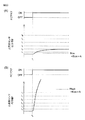
図7は、燃料カット制御開始時における上流側空燃比センサ40の出力電流Ifのタイムチャートである。このうち、図7(A)は、空燃比センサ40、41に応答性劣化が生じた場合のタイムチャートであり、図7(B)は、出力ゲインの低下が生じた場合におけるタイムチャートである。図中の破線は、空燃比センサ40、41に応答性劣化や出力ゲインの低下が生じていない場合を示している。なお、図7に示した例では、時刻t1において燃料カット制御が開始される。
FIG. 7 is a time chart of the output current If of the upstream air-
図7(A)に示したように、上流側空燃比センサ40に応答性劣化が生じている場合(実線)には、応答性劣化が生じていない場合(破線)に比べて出力電流Ifの上昇速度が上昇期間全体に亘って遅くなる。この結果、上流側空燃比センサ40に応答性劣化が生じている場合には、応答性劣化が生じていない場合に比べて、上昇時間Δtupが長くなる。
As shown in FIG. 7A, when the responsiveness deterioration occurs in the upstream air-fuel ratio sensor 40 (solid line), the output current If is not as high as when the responsiveness deterioration does not occur (broken line). The ascent rate slows over the entire ascent period. As a result, when the responsiveness deterioration occurs in the upstream side air-
一方、図7(B)に示したように、出力ゲインの低下が生じた場合、燃料カット制御中に上流側空燃比センサ40の出力電流Ifが最終的に収束する収束値が変化する。図7(B)に実線で示した例では、出力ゲインの低下が生じた結果、出力ゲインの低下が生じていない場合に比べて、出力電流Ifの収束値が小さくなっている。他方、このように出力ゲインが低下しても、上流側空燃比センサ40の出力電流Ifが最終的に収束するタイミングは変化しない。この結果、出力ゲインが低下すると、これに伴って上流側空燃比センサ40の出力電流Ifが低基準値Iflowから高基準値Ifhighまで変化するのにかかる上昇時間Δtupが長くなる。逆に、出力ゲインが上昇した場合には、上昇時間Δtupが短くなる。
On the other hand, as shown in FIG. 7B, when the output gain decreases, the convergence value at which the output current If of the upstream air-
このように、上流側空燃比センサ40に応答性劣化が生じている場合であっても、出力ゲインの低下が生じている場合であっても、応答性劣化が生じていない場合や出力ゲインの低下が生じていない場合に比べて、上昇時間Δtupが長くなる。したがって、上昇時間Δtupが長くなったときには上流側空燃比センサ40に応答性劣化が生じているのか或いは出力ゲインが低下しているのかを特定することができない。このため、実際には上流側空燃比センサ40には応答性劣化は生じておらず出力ゲインの低下のみが生じている場合であっても、上昇時間Δtupが長くなり、応答性劣化の異常が生じていると判定されることになる。
As described above, even when the responsiveness deterioration occurs in the upstream side air-
なお、図7では上流側空燃比センサ40の出力電流Ifにおける上昇時間Δtupを例にとって説明した。しかしながら、このような現象、すなわち出力ゲインの低下により応答性劣化が生じた場合と同様な変化が起こる現象は、上流側空燃比センサ40の出力電流Ifにおける低下時間Δtupや時間変化率にも生じる。また、このような現象は、上流側空燃比センサ40のみならず、下流側空燃比センサ41にもおいても生じる。
In FIG. 7, the increase time Δtup in the output current If of the upstream air-
<本願発明における異常診断>
ここで、図7からわかるように、空燃比センサ40、41に応答性劣化が生じた場合には、上昇時間Δtup等は変化するが、燃料カット制御中に空燃比センサ40、41の出力電流が収束する値は変化しない。一方、空燃比センサ40、41の出力ゲインが変化した場合には、上昇時間Δtup等のみならず、燃料カット制御中に空燃比センサ40、41の出力電流が収束する値も変化する。そこで、本実施形態では、燃料カット制御中に空燃比センサ40、41の出力電流が収束したときの収束値に基づいて、上昇時間Δtup等を補正するようにしている。そして、このようにして補正した後の上昇時間Δtup’等に基づいて空燃比センサ40、41の異常診断を行うようにしている。
<Abnormality diagnosis in the present invention>
Here, as can be seen from FIG. 7, when the responsiveness deterioration occurs in the air-
以下では、上流側空燃比センサ40の上昇時間Δtupを補正する場合を例にとって具体的に説明する。まず、図6を参照して説明したように、燃料カット制御を開始した後の上流側空燃比センサ40の出力電流Ifが低基準値Iflowから高基準値Ifhighまで変化するのにかかる時間である上昇時間Δtupが算出される。その後、上流側空燃比センサ40の出力電流Ifが一定の値に収束すると、このときの値が収束値Ifconとして検出される。
Hereinafter, a specific example will be described in which the rise time Δtup of the upstream air-
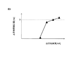
図8は、上流側空燃比センサ40の出力電流Ifが収束したときの収束値(以下、「出力収束値」ともいう)Ifconと、上昇時間(応答時間)の補正量Mとの関係を示す図である。図8からわかるように、出力収束値Ifconが大きくなるほど、上昇時間の補正量Mが増大せしめられる。特に図8に示した例では、出力収束値Ifconが或る所定の値よりも大きいときには上昇時間の補正量Mが0よりも大きい値とされる。一方、出力収束値Ifconが或る所定の値よりも小さいときには上昇時間の補正量が0よりも小さい値とされる。
FIG. 8 shows the relationship between the convergence value Ifcon when the output current If of the upstream air-
そして、図8に示したようなマップを用いて、上述したように検出された上流側空燃比センサ40の出力収束値Ifconに基づいて、上昇時間の補正量Mが算出される。その後、このようにして算出された上昇時間の補正量Mが上述したように算出された上昇時間Δtupに加算されたものが補正後の上昇時間Δtup’として算出される。したがって、出力収束値Ifconが或る所定の値よりも大きいときには補正後の上昇時間Δtup’は実際に検出された上昇時間Δtupよりも長い時間とされる。一方、出力収束値Ifconが或る所定の値よりも小さいときには補正後の上昇時間Δtup’は実際に検出された上昇時間Δtupよりも短い時間とされる。
Then, using the map as shown in FIG. 8, the correction amount M of the rising time is calculated based on the output convergence value Ifcon of the upstream air-
そして、このようにして算出された補正後の上昇時間Δtup’が異常判定基準上昇時間tuprefと比較される。比較の結果、補正後の上昇時間Δtup’が異常判定基準上昇時間tuprefよりも短い場合には上流側空燃比センサ40には異常が生じていないと判定される。一方、比較の結果、補正後の上昇時間Δtup’が異常判定基準上昇時間tupref以上である場合には、上流側空燃比センサ40には異常が生じていると判定される。
Then, the corrected rise time Δtup ′ calculated in this way is compared with the abnormality determination reference rise time tupref. As a result of the comparison, if the corrected increase time Δtup ′ is shorter than the abnormality determination reference increase time tupref, it is determined that no abnormality has occurred in the upstream air-
図9は、正常な空燃比センサ及び応答性が低下している空燃比センサの出力収束値と応答時間との関係を示す図である。図9(A)は上述したような応答時間の補正を行っていない場合を、図9(B)は上述したような応答時間の補正を行った場合をそれぞれ示している。上述したような応答時間の補正を行っていない場合には、図9(A)に示したように、空燃比センサが正常であっても出力収束値に応じて応答時間が変化することがわかる。この結果、空燃比センサが正常である場合に出力収束値が小さいときの応答時間と、空燃比センサの応答性が低下している場合に出力収束値が大きいときの応答時間とはほとんど同一の値となってしまう。このため、空燃比センサの応答性の低下を正確に検出することができない。 FIG. 9 is a diagram showing the relationship between the output convergence value and the response time of a normal air-fuel ratio sensor and an air-fuel ratio sensor whose responsiveness is lowered. FIG. 9A shows a case where the response time is not corrected as described above, and FIG. 9B shows a case where the response time is corrected as described above. When the response time is not corrected as described above, as shown in FIG. 9A, it can be seen that the response time changes according to the output convergence value even if the air-fuel ratio sensor is normal. . As a result, the response time when the output convergence value is small when the air-fuel ratio sensor is normal and the response time when the output convergence value is large when the response of the air-fuel ratio sensor is low are almost the same. Value. For this reason, it is impossible to accurately detect a decrease in responsiveness of the air-fuel ratio sensor.
一方、上述したような応答時間の補正を行っている場合には、図9(B)に示したように、少なくとも空燃比センサが正常であるときには出力収束値が変化しても応答時間はほとんど変化しない。この結果、空燃比センサが正常である場合に取り得る応答時間と空燃比センサの応答性が低下している場合に取り得る応答時間との間には差がある。このため、空燃比センサの応答性の低下を正確に検出することができる。すなわち、本実施形態によれば、空燃比センサの出力収束値が変化しても、すなわち空燃比センサの出力ゲインが変化しても、空燃比センサの応答性劣化の異常を正確に診断することができる。 On the other hand, when the response time is corrected as described above, as shown in FIG. 9B, at least when the air-fuel ratio sensor is normal, the response time is almost constant even if the output convergence value changes. It does not change. As a result, there is a difference between the response time that can be taken when the air-fuel ratio sensor is normal and the response time that can be taken when the response of the air-fuel ratio sensor is degraded. For this reason, it is possible to accurately detect a decrease in responsiveness of the air-fuel ratio sensor. That is, according to the present embodiment, even if the output convergence value of the air-fuel ratio sensor changes, that is, even if the output gain of the air-fuel ratio sensor changes, it is possible to accurately diagnose an abnormality in the responsiveness deterioration of the air-fuel ratio sensor. Can do.
なお、本実施形態では、上流側空燃比センサ40の出力収束値Ifconの算出は、以下のようにして行われる。まず、上流側空燃比センサ40の出力電流Ifの収束判定が行われる。出力電流Ifの収束判定は、例えば、燃料カット制御が開始されてからの経過時間が予め定められた収束判定基準時間以上であるか否かによって行われ、収束判定基準時間以上経過しているときに出力電流Ifが収束していると判定される。この収束判定基準時間は、燃料カット制御を開始してから上流側空燃比センサ40の出力電流Ifが収束するまでに通常かかる時間の最大値、或いはこの最大値と僅かに異なる時間とされる。或いは、出力電流Ifの収束判定は、出力電流Ifの単位時間当たりの変化量が収束判定基準量以下であるか否かによって行われてもよく、この場合、収束判定基準量以下であるときに出力電流Ifが収束していると判定される。
In the present embodiment, the calculation of the output convergence value Ifcon of the upstream air-
そして、このように上流側空燃比センサ40の出力電流Ifが収束したと判定されてから予め定められた所定の時間が経過するまでの測定期間に亘って上流側空燃比センサ40の出力電流Ifが検出される。そして、この測定機関における上流側空燃比センサ40の出力電流の平均値が出力収束値Ifconとされる。
Then, the output current If of the upstream air-
また、下流側空燃比センサ41の出力収束値Irconも同様に算出される。ただし、下流側空燃比センサ41の収束判定は、燃料カット制御が開始されてからの経過時間ではなく、燃料カット制御の開始後に燃焼室5に供給された積算吸入空気量が基準積算量に到達したと推定されてからの経過時間に基づいて行われる。又は、燃料カット制御の開始後に下流側空燃比センサ41の出力電流がゼロよりも大きいリーン判定基準値以上になってからの経過時間に基づいて行われる。このように収束判定を行うのは、上流側排気浄化触媒20に酸素が吸蔵されることにより、燃料カット制御の開始後に下流側空燃比センサ41の出力電流の上昇が遅れるためである。なお、予め定められた基準積算量は、上流側排気浄化触媒20の未使用時の最大吸蔵可能酸素量Cmaxに相当する酸素量が含まれる空気の量以上とされる。また、リーン判定基準値Irleanは、理論空燃比よりも僅かにリーンである予め定められたリーン判定空燃比(例えば、14.65)に相当する値である。
Further, the output convergence value Ircon of the downstream air-
或いは、下流側空燃比センサ41の収束判定は、上流側排気浄化触媒の酸素吸蔵量が最大吸蔵可能酸素量に到達したと推定された後における出力電流Ifの単位時間当たりの変化量に基づいて行われる。又は、燃料カット制御の開始後に下流側空燃比センサ41の出力電流がリーン判定基準値以上になった後における出力電流Ifの単位時間当たりの変化量に基づいて行われる。
Alternatively, the convergence determination of the downstream side air-
なお、上記実施形態では、図8に示したように出力収束値Ifconに基づいて上昇時間の補正量Mを算出している。しかしながら、出力収束値Ifconに基づいて上昇時間の補正率を算出するようにしてもよい。この場合、このようにして算出された補正率を実際に検出された上昇時間Δtupに乗算することで補正上昇率Δtup’が算出されることになる。また、補正率は、出力収束値Ifconが大きくなるほど増大せしめられる。 In the above embodiment, as shown in FIG. 8, the correction amount M of the rising time is calculated based on the output convergence value Ifcon. However, the correction rate of the rising time may be calculated based on the output convergence value Ifcon. In this case, the corrected increase rate Δtup ′ is calculated by multiplying the actually calculated increase time Δtup by the correction rate calculated in this way. Further, the correction rate is increased as the output convergence value Ifcon increases.
また、上述した例では、上流側空燃比センサ40における上昇時間Δtupを例にとったが、下流側空燃比センサ41の上昇時間Δtup、両空燃比センサ40、41における低下時間Δtdwnについても同様に空燃比センサ40、41の出力収束値に基づいて補正を行うことが可能である。
In the above example, the rise time Δtup in the upstream side air-
<フローチャート>
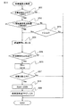
図10は、本実施形態の異常診断装置によって行われる上流側空燃比センサ40の異常診断処理の制御ルーチンを示すフローチャートである。図示した制御ルーチンは一定時間間隔の割り込みによって実行される。
<Flowchart>
FIG. 10 is a flowchart showing a control routine for abnormality diagnosis processing of the upstream air-
図10に示した例では、まず、ステップS11において、異常診断処理の実行条件が成立しているか否かが判定される。異常診断処理の実行条件が成立する場合とは、例えば、以下のような条件の少なくとも一部、好ましくは全てを満たしている場合である。
・機関冷却水の温度を検出する温度センサ(図示せず)によって検出された機関冷却水の温度が所定温度以上であること。
・前回の燃料カット制御が終了してからの経過時間が予め定められた所定時間以上であること。
・機関高負荷運転時等に一時的に燃料噴射量を増量する増量制御が終了してからの経過時間が予め定められた所定時間以上であること。
・上流側空燃比センサ40の応答性に関する異常診断が未だに終了していないこと。
In the example shown in FIG. 10, first, in step S11, it is determined whether or not an execution condition for the abnormality diagnosis process is satisfied. The case where the execution condition of the abnormality diagnosis process is satisfied is, for example, a case where at least a part, preferably all of the following conditions are satisfied.
-The temperature of the engine cooling water detected by a temperature sensor (not shown) for detecting the temperature of the engine cooling water is equal to or higher than a predetermined temperature.
-The elapsed time from the end of the previous fuel cut control is not less than a predetermined time.
-The elapsed time after the increase control for temporarily increasing the fuel injection amount at the time of engine high load operation or the like is not less than a predetermined time.
The abnormality diagnosis regarding the responsiveness of the upstream air-
ステップS11において、異常診断処理の実行条件が成立していないと判定された場合、例えば、温度センサ(図示せず)によって検出された機関冷却水の温度が所定温度未満である場合、制御ルーチンが終了せしめられる。一方、ステップS11において、異常診断処理の実行条件が成立していると判定された場合、ステップS12へと進む。ステップS12では図11に示す出力収束値Ifconの算出処理が実行され、次いで、ステップS13では図12に示す上昇時間Δtupの算出処理が実行される。 If it is determined in step S11 that the condition for executing the abnormality diagnosis process is not satisfied, for example, if the temperature of the engine coolant detected by a temperature sensor (not shown) is less than a predetermined temperature, the control routine It will be terminated. On the other hand, if it is determined in step S11 that the condition for executing the abnormality diagnosis process is satisfied, the process proceeds to step S12. In step S12, the output convergence value Ifcon shown in FIG. 11 is calculated, and in step S13, the rise time Δtup shown in FIG. 12 is executed.
その後、ステップS14では、収束値算出フラグ及び上昇時間算出フラグがONになっているか否かが判定される。収束値算出フラグは、出力収束値Ifconの算出が完了するとONにされ、その前にはOFFとされるフラグである。また、上昇時間算出フラグは、上昇時間Δtupの算出が完了するとONにされ、その前にはOFFとされるフラグである。ステップS14において、収束値算出フラグ及び上昇時間算出フラグのうち少なくともいずれか一方がOFFであると判定された場合には、上流側空燃比センサ40の異常診断を行うのに十分なデータが集まっていないため、制御ルーチンが終了せしめられる。
Thereafter, in step S14, it is determined whether or not the convergence value calculation flag and the rising time calculation flag are ON. The convergence value calculation flag is turned on when the calculation of the output convergence value Ifcon is completed, and is turned off before that. Further, the rising time calculation flag is a flag that is turned ON when the calculation of the rising time Δtup is completed, and is turned OFF before that. In step S14, if it is determined that at least one of the convergence value calculation flag and the rising time calculation flag is OFF, sufficient data is collected to perform abnormality diagnosis of the upstream air-
一方、ステップS14において、収束値算出フラグ及び上昇時間算出フラグがONになっていると判定された場合には、ステップS15へと進む。ステップS15では、ステップS12において算出された出力収束値Ifconに基づいて、図8に示したようなマップを用いて補正量Mが算出される。次いで、ステップS16では、ステップS13で算出された上昇時間ΔtupにステップS15で算出された補正量Mを加算した値(Δtup+M)、すなわち補正後の上昇時間Δtup’が異常判定基準上昇時間tuprefよりも短いか否かが判定される。補正後の上昇時間Δtup’(=Δtup+M)が異常判定基準上昇時間tuprefよりも短いと判定された場合にはステップS17へと進む。ステップS17では、上流側空燃比センサ40は正常であると判定され、ステップS19へと進む。一方、ステップS16において、補正後の上昇時間Δtup’が異常判定基準上昇時間tupref以上であると判定された場合にはステップS18へと進む。ステップS18では、上流側空燃比センサ40には異常が生じていると判定され、警告灯が点灯せしめられ、ステップS19へと進む。ステップS19では、収束値算出フラグ及び上昇時間算出フラグがOFFにリセットされ、制御ルーチンが終了せしめられる。
On the other hand, when it is determined in step S14 that the convergence value calculation flag and the rising time calculation flag are ON, the process proceeds to step S15. In step S15, based on the output convergence value Ifcon calculated in step S12, the correction amount M is calculated using a map as shown in FIG. Next, in step S16, a value obtained by adding the correction amount M calculated in step S15 to the increase time Δtup calculated in step S13 (Δtup + M), that is, the corrected increase time Δtup ′ is greater than the abnormality determination reference increase time tupref. It is determined whether it is short. If it is determined that the corrected rise time Δtup '(= Δtup + M) is shorter than the abnormality determination reference rise time tupref, the process proceeds to step S17. In step S17, it is determined that the upstream air-
図11は、出力収束値Ifconの算出処理の制御ルーチンを示すフローチャートである。図11に示した制御ルーチンは、図10のステップS12において実行される。 FIG. 11 is a flowchart showing a control routine of the output convergence value Ifcon calculation process. The control routine shown in FIG. 11 is executed in step S12 of FIG.
図11に示したように、まず、ステップS31では、収束値算出フラグがOFFであるか否かが判定される。収束値算出フラグがONである場合には、既に収束値Ifconの算出が終了しているため、制御ルーチンが終了せしめられる。一方、ステップS31において、収束値算出フラグがOFFであると判定された場合には、ステップS32へと進む。 As shown in FIG. 11, first, in step S31, it is determined whether or not the convergence value calculation flag is OFF. If the convergence value calculation flag is ON, since the calculation of the convergence value Ifcon has already been completed, the control routine is terminated. On the other hand, if it is determined in step S31 that the convergence value calculation flag is OFF, the process proceeds to step S32.
ステップS32では、燃料カット制御(FC)を開始してからの経過時間tfcが予め定められた収束判定基準時間tfcref以上であるか否かが判定される。この収束判定基準時間tfcrefは、燃料カット制御を開始してから上流側空燃比センサ40の出力電流Ifが収束するまでに通常かかる時間の最大値、或いはこの最大値と僅かに異なる時間とされる。燃料カット制御を開始してからの経過時間tfcが収束判定基準時間trefよりも短いと判定された場合には、上流側空燃比センサ40の出力電流Ifが収束していないため、制御ルーチンが終了せしめられる。一方、燃料カット制御を開始してからの経過時間tfcが収束判定基準時間tref以上であると判定された場合にはステップS33へと進む。
In step S32, it is determined whether or not an elapsed time tfc from the start of the fuel cut control (FC) is equal to or greater than a predetermined convergence determination reference time tfcref. This convergence determination reference time tfcref is the maximum value of the time normally taken from the start of fuel cut control until the output current If of the upstream air-
ステップS33では、上流側空燃比センサ40の今回の出力電流Ifを出力電流積算値ΣIfに加算したものが新たな出力電流積算値ΣIfとされる。次いで、ステップS34では、ステップS33における出力電流Ifの積算回数がN回以上であるか否か、すなわち上流側空燃比センサ40が収束したと判定してからの経過時間が所定時間以上であるか否かが判定される。出力電流Ifの積算回数がN回よりも少ないと判定された場合には、適切な出力収束値Ifconを算出することができないため、制御ルーチンが終了せしめられる。一方、出力電流Ifの積算回数がN回以上であると判定された場合にはステップS35へと進む。ステップS35では、出力電流積算値ΣIfを積算回数Nで除算した値が出力収束値Ifconとして算出される。次いで、ステップS36では、収束値算出フラグがONにセットされ、制御ルーチンが終了せしめられる。
In step S33, a value obtained by adding the current output current If of the upstream air-
図12は、上昇時間Δtupの算出処理の制御ルーチンを示すフローチャートである。図12に示した制御ルーチンは、図10のステップS13において実行される。 FIG. 12 is a flowchart showing a control routine of a calculation process of the rising time Δtup. The control routine shown in FIG. 12 is executed in step S13 of FIG.
図12に示したように、まず、ステップS41では、上昇時間算出フラグがOFFであるか否かが判定される。上昇時間算出フラグがONである場合には、既に上昇時間Δtupの算出が終了しているため、制御ルーチンが終了せしめられる。一方、ステップS41において、上昇時間算出フラグがOFFであると判定された場合には、ステップS42へと進む。 As shown in FIG. 12, first, in step S41, it is determined whether or not the rising time calculation flag is OFF. When the rising time calculation flag is ON, since the calculation of the rising time Δtup has already been completed, the control routine is ended. On the other hand, if it is determined in step S41 that the rising time calculation flag is OFF, the process proceeds to step S42.
ステップS42では、現在、燃料カット制御(FC)中であるか否かが判定される。燃料カット制御中でないと判定された場合には、上昇時間の算出ができないため制御ルーチンが終了せしめられる。その後、燃料カット制御が開始されると、ステップS42において、現在、燃料カット制御中であると判定されてステップS43へと進む。ステップS43では、上流側空燃比センサ40の出力電流Ifが低基準値Iflowよりも低いか否かが判定される。
In step S42, it is determined whether or not fuel cut control (FC) is currently in progress. If it is determined that the fuel cut control is not in progress, the control routine is terminated because the rise time cannot be calculated. Thereafter, when the fuel cut control is started, it is determined in step S42 that the fuel cut control is currently being performed, and the process proceeds to step S43. In step S43, it is determined whether or not the output current If of the upstream air-
ステップS43において、上流側空燃比センサ40の出力電流Ifが低基準値Iflowよりも低いと判定された場合には、ステップS44へと進む。ステップS44では、応答時間Δtupがゼロにリセットされ、制御ルーチンが終了せしめられる。一方、燃料カット制御開始から時間が経過して排気空燃比の上昇に伴って上流側空燃比センサ40の出力電流Ifが上昇すると、次の制御ルーチンでは、ステップS43において出力電流Ifが低基準値Iflow以上であると判定され、ステップS45へと進む。
If it is determined in step S43 that the output current If of the upstream air-
ステップS45では、上流側空燃比センサ40の出力電流Ifが高基準値Ifhighよりも小さいか否かが判定される。ステップS45において、出力電流Ifが高基準値Ifhighよりも小さいと判定された場合にはステップS46へと進む。ステップS46では、上昇時間Δtupに微少時間Δt(制御ルーチンの実行間隔に相当)を加算した値が新たな上昇時間Δtupとされ、制御ルーチンが終了せしめられる。その後、排気空燃比の更なる上昇に伴って上流側空燃比センサ40の出力電流Ifが上昇すると、次の制御ルーチンでは、ステップS45において出力電流Ifが高基準値Ifhig以上であると判定され、ステップS47へと進む。ステップS47では、応答時間算出フラグがONにセットされ、制御ルーチンが終了せしめられる。
In step S45, it is determined whether or not the output current If of the upstream air-
なお、上記フローチャートでは、上流側空燃比センサ40の上昇時間Δtupに基づいて上流側空燃比センサ40の異常診断を行った場合を示している。しかしながら、同様な制御ルーチンを用いて、上流側空燃比センサ40の低下時間Δtdwnに基づいて上流側空燃比センサ40の異常診断を行うことができる。ただし、この場合、図12に示した上昇時間算出処理の代わりに、図13に示した低下時間算出処理が行われる(図13のステップ番号は、図12における対応するステップの番号にダッシュを付した番号となっている)。図13に示した低下時間算出処理の制御ルーチンステップS42’において、燃料カット制御の終了後であるか否かが判定されることになる。また、ステップS43’においては、下流側空燃比センサ41の出力電流Irが高基準値Irhihgよりも高いか否かが判定される。加えて、ステップS45’においては、下流側空燃比センサ41の出力電流Irが低基準値Irlowよりも高いか否かが判定される。
Note that the above flowchart shows a case where abnormality diagnosis of the upstream air-
加えて、同様な制御ルーチンを用いて、下流側空燃比センサ41の上昇時間Δtupや低下時間Δtdwnに基づいて下流側空燃比センサ41の異常診断を行うこともできる。この場合、図11に示した収束値算出処理の代わりに、図14に示した収束値算出処理が行われる。
In addition, the abnormality diagnosis of the downstream air-
図14は、下流側空燃比センサ41における出力収束値Irconの算出処理の制御ルーチンを示すフローチャートである。なお、図14におけるステップS56〜S59は、図11におけるステップS33〜S36と同様であることから説明を省略する。
FIG. 14 is a flowchart showing a control routine for the calculation process of the output convergence value Ircon in the downstream side air-
図14に示したように、先ず、ステップS51では、収束値算出フラグがOFFであるか否かが判定される。収束値算出フラグがOFFであると判定された場合には、ステップS52へと進む。ステップS52では、燃料カット制御が開始されてから燃焼室5に供給された吸入空気量の積算値(積算空気量)ΣMcが予め定められた基準積算量Mcref以上であるか否かが判定される。加えて、ステップS53では、下流側空燃比センサ41の出力電流Irがゼロよりも大きいリーン判定基準値Irlean以上となったか否かが判定される。
As shown in FIG. 14, first, in step S51, it is determined whether or not the convergence value calculation flag is OFF. If it is determined that the convergence value calculation flag is OFF, the process proceeds to step S52. In step S52, it is determined whether or not the integrated value (integrated air amount) ΣMc of the intake air amount supplied to the combustion chamber 5 after the fuel cut control is started is equal to or larger than a predetermined reference integrated amount Mcref. . In addition, in step S53, it is determined whether or not the output current Ir of the downstream air-
ステップS52及びS53において、燃料カット制御開始後の積算空気量ΣMcが基準積算量Mcrefよりも少なく且つ下流側空燃比センサ41の出力電流Irもリーン判定基準値Irleanよりも小さいと判定された場合には、上流側排気浄化触媒20の酸素吸蔵量が最大吸蔵可能酸素量Cmaxに到達していない可能性があることを意味する。したがって、上流側排気浄化触媒20から流出する排気ガスの空燃比はほぼ理論空燃比となっており、下流側空燃比センサ41の出力電流Irはゼロからあまり変化しない。このため、このような場合には、上昇時間Δtupを検出することはできない。したがって、このような場合には、制御ルーチンが終了せしめられる。
When it is determined in steps S52 and S53 that the integrated air amount ΣMc after the start of the fuel cut control is smaller than the reference integrated amount Mcref and the output current Ir of the downstream air-
一方、ステップS52において燃料カット制御開始後の積算空気量ΣMcが基準積算量Mcref以上である場合、又はステップS53において下流側空燃比センサ41の出力電流Irがリーン判定基準値Irlean以上であると判定された場合には、上流側排気浄化触媒20の酸素吸蔵量が最大吸蔵可能酸素量Cmaxに到達していることを意味する。したがって、上流側排気浄化触媒20から流出する排気ガスの空燃比は徐々に上昇していく。このため、このような場合には、ステップS54へと進み、経過時間tfcに微少時間Δt(制御ルーチンの実行間隔に相当)が加算した値が新たな経過時間tfcとされ、経過時間の計測が開始される。その後、ステップS55へと進み、ステップS54で算出された経過時間tfcが予め定められた収束判定基準時間tfcref以上であるか否かが判定される。ステップS54で算出された経過時間tfcが収束判定基準時間tfcrefよりも短いと判定された場合には、下流側空燃比センサ41の出力電流Irが収束していないため、制御ルーチンが終了せしめられる。一方、ステップS54で算出された経過時間tfcが収束判定基準時間tfcref以上であると判定された場合にはステップS56へと進む。
On the other hand, when the integrated air amount ΣMc after the start of the fuel cut control is greater than or equal to the reference integrated amount Mcref in step S52, or it is determined in step S53 that the output current Ir of the downstream air-
<第一実施形態の第一変形例>
次に、図15及び図16を参照して、本発明の第一実施形態の第一変形例に係る異常診断装置について説明する。本変形例では、燃料カット制御中に空燃比センサ40、41の出力電流が収束するときの推移に応じて、異常診断制御の実行を中止するようにしている。
<First Modification of First Embodiment>
Next, with reference to FIG.15 and FIG.16, the abnormality diagnosis apparatus which concerns on the 1st modification of 1st embodiment of this invention is demonstrated. In this modification, the execution of the abnormality diagnosis control is stopped according to the transition when the output currents of the air-
ところで、空燃比センサ40、41の出力ゲインは、上述したように、空燃比センサ40、41周りの排気ガスの圧力等に応じて変化する。したがって、燃料カット制御の開始後或る程度の時間が経過しても、例えば空燃比センサ40、41周りの排気ガスの圧力が変動すると、空燃比センサ40、41の出力電流が一定の値に収束しない場合がある。この様子を、図15に示す。図15中の実線は、燃料カット制御中に上流側空燃比センサ40の出力ゲインが変動している場合における出力電流Ifの推移を表している。一方、図15中の破線は、燃料カット制御中に上流側空燃比センサ40の出力ゲインが変動していない場合における出力電流Ifの推移を表している。
By the way, as described above, the output gain of the air-
ここで、上述したように、上流側空燃比センサ40の出力電流Ifの時刻t2から時刻t3までの平均値が出力収束値Ifconとして算出される。このため、図中に破線で示したように燃料カット制御中に上流側空燃比センサ40の出力ゲインが変動していなければ、算出される出力収束値はIfcon1として算出される。一方、図中に実線で示したように燃料カット制御中に上流側空燃比センサ40の出力ゲインが時刻t2から時刻t3までに間に変動すると、算出される出力収束値はIfcon1とは異なる値であるIfcon2となる。このように、出力収束値を算出するための測定期間(時刻t2〜時刻t3)中に上流側空燃比センサ40の出力ゲインが変動してしまうと、出力ゲインが変動していないときとは異なる値となってしまう。この結果、出力ゲインが変動していると、算出される出力収束値Ifconは、上流側空燃比センサ40の出力電流Ifが低基準値Iflowから高基準値Ifhighまで推移している間の出力ゲインに対応する値とは異なる値になってしまう。このため、算出された出力収束値Ifconによっては適切な応答時間補正量を算出することができず、その結果、上昇時間Δtupを適切に補正することができない。
Here, as described above, the average value from the time t 2 of the output current If of the upstream air-
そこで、本変形例では、燃料カット制御中における上流側空燃比センサ40の出力収束値を算出するための測定期間中に上流側空燃比センサ40の出力電流Ifが大きく変動したときには、上流側空燃比センサ40の異常診断を行わないようにしている。具体的には、本変形例では、上流側空燃比センサ40の出力収束値を算出するにあたって出力電流Ifを積算している間(図15の時刻t2から時刻t3)の出力電流Ifの最大値と最小値との差が予め定められた所定の診断中止基準値よりも大きい場合には、異常診断を行わないこととしている。これにより、上昇時間Δtupを適切に算出することができないときには上流側空燃比センサ40の異常診断が行われず、よって適切でない異常診断が実行されてしまうことが防止される。
Therefore, in the present modification, when the output current If of the upstream air-
なお、上記変形例では、出力収束値の算出中における出力電流Ifの最大値と最小値との差に基づいて異常診断実行の可否を決定している。しかしながら、出力電流Ifが変動している程度を示すパラメータであれば、最大値と最小値との差以外のパラメータに基づいて異常診断実行の可否を決定してもよい。このようなパラメータとしては、例えば、出力収束値を算出するための測定期間中の上流側空燃比センサ40の出力電流Ifにおける最大変化率や平均変化率(変化率の絶対値を平均したもの)等が挙げられる。この場合、出力電流Ifにおける最大変化率や平均変化率が予め定められた所定の診断中止基準値よりも大きい場合には、異常診断を行わないこととされる。すなわち、本変形例では、出力電流Ifの変動を示すパラメータの値が予め定められた診断中止基準値よりも変動が大きいことを表す値であるときには、上流側空燃比センサ40の異常診断を行いこととされる。なお、上記例では、上流側空燃比センサ40を例にとって説明したが、下流側空燃比センサ41にも同様に適用が可能である。
In the above modification, whether or not abnormality diagnosis can be performed is determined based on the difference between the maximum value and the minimum value of the output current If during calculation of the output convergence value. However, as long as the parameter indicates the degree to which the output current If varies, whether or not the abnormality diagnosis can be performed may be determined based on a parameter other than the difference between the maximum value and the minimum value. As such a parameter, for example, the maximum change rate or the average change rate (average value of the change rate) of the output current If of the upstream air-
図16は、出力収束値Ifconの算出処理の制御ルーチンを示す、図11と同様なフローチャートである。図16に示した制御ルーチンは、図10のステップS12において実行される。なお、図16のステップS61〜S63、S68、S70〜S71は、図11のステップS31〜S36と同様であるため説明を省略する。 FIG. 16 is a flowchart similar to FIG. 11 showing a control routine for the calculation process of the output convergence value Ifcon. The control routine shown in FIG. 16 is executed in step S12 of FIG. Note that steps S61 to S63, S68, and S70 to S71 in FIG. 16 are the same as steps S31 to S36 in FIG.
図16のステップS64では、現在の上流側空燃比センサ40の出力電流Ifが現在保存されている出力最大値Ifmaxよりも大きいか否かが判定され、ステップS65では、現在の上流側空燃比センサ40の出力電流Ifが現在保存されている出力最小値Ifminよりも小さいか否かが判定される。ステップS64、S65において、現在の出力電流Ifが出力最大値Ifmaxよりも大きいと判定された場合には、ステップS66へと進む。ステップS66では、現在の出力電流Ifが出力最大値Ifmaxとされ、すなわち出力最大値Ifmaxが更新されて、ステップS68へと進む。一方、ステップS64、S65において、現在の出力電流Ifが出力最小値Ifminよりも小さいと判定された場合には、ステップS67へと進む。ステップS67では、現在の出力電流Ifが出力最小値Ifminとされ、すなわち出力最小値Ifminが更新されて、ステップS68へと進む。加えて、ステップS64、S65において、現在の出力電流Ifが出力最小値Ifmin以上であって出力最大値Ifmax以下である場合には、ステップS66、S67を経由することなく、ステップS68へと進む。
In step S64 of FIG. 16, it is determined whether or not the current output current If of the upstream air-
ステップS68では、出力電流Ifの積算回数がN回以上であるか否かが判定され、N回以上であると判定された場合には、ステップS69へと進む。ステップS69では、出力最大値Ifmaxと出力最小値Ifminとの差ΔIf(Ifmax−Ifmin)が予め定められた診断中止基準値Ifrefよりも小さいか否かが判定される。差ΔIfが診断中止基準値Ifrefよりも小さいと判定された場合、すなわち出力収束値の算出中における出力電流Ifの変動が小さい場合には、ステップS70へと進む。一方、差ΔIfが診断中止基準値Ifref以上であると判定された場合、すなわち出力収束値の算出中における出力電流Ifの変動が大きい場合には、ステップS72へと進む。ステップS72では、上流側空燃比センサ40の異常診断が一時的に休止され、制御ルーチンが終了せしめられる。
In step S68, it is determined whether or not the number of integrations of the output current If is N or more. If it is determined that the output current If is N or more, the process proceeds to step S69. In step S69, it is determined whether or not a difference ΔIf (Ifmax−Ifmin) between the maximum output value Ifmax and the minimum output value Ifmin is smaller than a predetermined diagnosis stop reference value Ifref. When it is determined that the difference ΔIf is smaller than the diagnosis cancellation reference value Ifref, that is, when the fluctuation of the output current If is small during the calculation of the output convergence value, the process proceeds to step S70. On the other hand, when it is determined that the difference ΔIf is greater than or equal to the diagnosis cancellation reference value Ifref, that is, when the fluctuation of the output current If during the calculation of the output convergence value is large, the process proceeds to step S72. In step S72, the abnormality diagnosis of the upstream air-
<第一実施形態の第二変形例>
次に、図17を参照して、本発明の第一実施形態の第二変形例に係る異常診断装置について説明する。本変形例では、空燃比センサ40、41の出力収束値に応じて異常診断制御の実行を中止するようにしている。
<Second Modification of First Embodiment>
Next, with reference to FIG. 17, an abnormality diagnosis apparatus according to a second modification of the first embodiment of the present invention will be described. In this modification, the execution of the abnormality diagnosis control is stopped according to the output convergence values of the air-
ところで、図8に示した出力収束値と応答時間補正量(上昇時間補正量)との関係は、応答性劣化の生じていない空燃比センサ40、41を用いて出力ゲインを変化させることによって算出される。このとき、出力ゲインは、出力ゲインが小さすぎて異常と判定されるような値(縮小異常検出レベル)から、出力ゲインが大きすぎて異常と判定されるような値(拡大異常検出レベル)まで変化せしめられる。このため、実際の出力ゲインが縮小異常検出レベルよりも小さい場合であっても、応答時間補正量は縮小異常検出レベルに相当する補正量とされる。同様に、実際の出力ゲインが拡大異常検出レベルよりも大きい場合であっても、応答時間補正量は拡大異常検出レベルに相当する補正量とされる。
By the way, the relationship between the output convergence value and the response time correction amount (rise time correction amount) shown in FIG. 8 is calculated by changing the output gain using the air-
この結果、応答性劣化の生じていない空燃比センサ40、41を用いた場合であっても、出力ゲインが縮小異常検出レベルよりも小さいときには算出される応答時間が長くなり過ぎるため、応答時間補正量によっては応答時間を十分に短く補正することができない。このため、応答性劣化が生じていない空燃比センサ40、41を用いているにも関わらず、補正後の応答時間に基づいて空燃比センサ40、41に応答性劣化が生じていると判定されてしまうことになる。一方、応答性劣化の生じている空燃比センサ40、41を用いた場合であっても、出力ゲインが拡大異常検出レベルよりも大きいときには算出される応答時間が短くなり過ぎるため、応答時間補正量によっては応答時間を十分に長く補正することができない。その結果、応答性劣化が生じている空燃比センサ40を用いているにも関わらず、補正後の応答時間に基づいて空燃比センサ40に応答性劣化が生じていないと判定されてしまうことになる。
As a result, even when the air-
そこで、本実施形態では、このように出力ゲインが或る程度大きな値(例えば、拡大異常検出レベル)以上である場合、又は出力ゲインが或る程度小さな値(例えば、縮小異常検出レベル)以下である場合には、空燃比センサ40の異常判定を行わないようにしている。
Therefore, in the present embodiment, when the output gain is a certain value (for example, an expansion abnormality detection level) or more, or when the output gain is a certain value (for example, a reduction abnormality detection level) or less. In some cases, the abnormality determination of the air-
図17を参照して具体的に説明する。図17は燃料カット制御の開始時における上流側空燃比センサ40の出力電流Ifのタイムチャートである。図中の破線は、出力ゲインが適正値である場合における上流側空燃比センサ40の出力値の推移を示している。上流側空燃比センサ40の出力収束値Ifconが、図17に実線Aで示したように、予め定められた高側診断中止基準値(例えば、拡大異常検出レベルに相当)以上である場合には、上流側空燃比センサ40の異常診断は行われない。同様に、上流側空燃比センサ40の出力収束値Ifconが、図17に実線Bで示したように、予め定められた低側診断中止基準値(例えば、縮小異常検出レベルに相当)以下である場合には、上流側空燃比センサ40の異常診断は行われない。すなわち、本変形例では、燃料カット制御の開始後に空燃比センサの出力電流が収束したときの出力収束値が予め定められた範囲(例えば、縮小異常検出レベルよりも大きくて拡大異常検出レベルよりも小さい範囲に相当)外の値であった場合には、上流側空燃比センサ40の異常診断は行われない。
This will be specifically described with reference to FIG. FIG. 17 is a time chart of the output current If of the upstream air-
これにより、空燃比センサ40の出力ゲインが縮小異常検出レベル以下や拡大異常検出レベル以上になっても応答性劣化を適切に診断することができるようになる。
As a result, even when the output gain of the air-
<第二実施形態>
次に、図18及び図19を参照して、本発明の第二実施形態の異常診断装置について説明する。第二実施形態の異常診断装置の構成及び制御は基本的に第一実施形態の異常診断装置の構成及び制御と同様である。
<Second embodiment>
Next, with reference to FIG.18 and FIG.19, the abnormality diagnosis apparatus of 2nd embodiment of this invention is demonstrated. The configuration and control of the abnormality diagnosis device of the second embodiment are basically the same as the configuration and control of the abnormality diagnosis device of the first embodiment.
ここで、上述した実施形態では、空燃比センサ40、41の出力収束値に基づいて、上昇時間Δtup及び低下時間Δtdwnを補正するようにしていた。しかしながら、本実施形態では、燃料カット制御中の空燃比センサ40、41の出力収束値に基づいて高基準値Ifhigh及び低基準値Iflowを変更するようにしている。
Here, in the above-described embodiment, the rise time Δtup and the fall time Δtdwn are corrected based on the output convergence values of the air-
具体的には、まず、図18の時刻t0において燃料カット制御が開始されると、上流側空燃比センサ40の出力電流Ifが逐次検出されると共に、計測された出力電流Ifが計測時刻と共に一定時間間隔毎に又は一定出力値間隔毎にECU31のRAM33に保存される。その後、上述した実施形態と同様に、出力収束値Ifconが算出される。算出された出力収束値Ifconに低基準値用係数Aを乗算したものを低基準値Iflowとして算出する(Iflow=Ifcon×A)。ここで、低基準値用係数Aは0よりも大きく1よりも小さい値とされる。加えて、算出された出力収束値Ifconに高基準値用係数Bを乗算したものを高基準値Ifhighとして算出する(Ifhigh=Ifcon×B)。ここで、高基準値用係数Bは、0よりも大きく1よりも小さい値とされると共に低基準値用係数Aよりも大きな値とされる。
Specifically, first, when fuel cut control is started at time t 0 in FIG. 18, the output current If of the upstream air-
その後、図18に示したように、RAM33に保存されている上流側空燃比センサ40の出力電流If及びその到達時刻に基づいて、出力電流Ifが低基準値Iflowに到達した時刻tA及び高基準値Ifhighに到達した時刻tBが算出される。このようにして算出された時刻tA及び時刻tBの差を算出することにより、上昇時間Δtupが算出される。この上昇時間Δtupが予め定められた異常判定基準上昇時間以上である場合には空燃比センサ40、41に異常が生じていると判定される。これにより、本実施形態によれば、上流側空燃比センサ40の異常を正確に診断することができる。また、同様な手法は、下流側空燃比センサ41の異常診断を行うのにも用いることができる。
After that, as shown in FIG. 18, based on the output current If of the upstream air-
ところで、燃料カット制御開始後、時刻と上流側空燃比センサ40の出力電流Ifとの関係を連続的にRAM33に保存することになると、RAM33に大きな記憶容量が必要になる。そこで、本実施形態では、上流側空燃比センサ40の出力電流Ifが予め定められた複数の出力基準値i1〜i6に到達した時刻t1〜t6のみがRAM33に記憶される(図18参照)。ここで、複数の出力基準値i1〜i6は、0以上であって大気ガスに相当する出力電流よりも小さい値とされ、出力基準値i1からi6に向かって徐々に大きくなる値とされる(i1<i2<i3<・・・)。また、各出力基準値i1〜i6は隣り合う値と互いに同一値だけ離れた値とされる(例えば、i3−i2=i2−i1)。なお、図示した例ではi1〜i6の六つの出力基準値が用いられているが、これよりも多くてもよいし、少なくてもよい。
By the way, if the relationship between the time and the output current If of the upstream air-
その後、出力収束値Ifconが算出され、この出力収束値Ifconを用いて高基準値Ifhigh及び低基準値Iflowが算出される。しかしながら、このように算出された高基準値Ifhigh及び低基準値Iflowは、多くの場合、出力基準値i1〜i6と一致しない。そこで、本実施形態では、このようにして算出された高基準値Ifhighに最も近い二つ出力基準値(図18に示した例ではi4及びi5)に到達した時刻(図18に示した例では、t4及びt5)に基づいて下記式(1)のような式を用いて高基準値Ifhighに到達した時刻tBが算出される。
tB=(t[x+1]−t[x])/(i[x+1]−i[x])×(Ifhigh−i[x])+t[x] …(1)
なお、上記式(1)において、i[x]は、i[x]≦Ifhigh<i[x+1]となるように選択される。したがって、図18に示した例では、i(x)はi4とされる。
Thereafter, the output convergence value Ifcon is calculated, and the high reference value Ifhigh and the low reference value Iflow are calculated using the output convergence value Ifcon. However, the high reference value Ifhigh and the low reference value Iflow calculated in this way often do not coincide with the output reference values i 1 to i 6 . Therefore, in the present embodiment, the time when the two output reference values (i 4 and i 5 in the example shown in FIG. 18) that are closest to the high reference value Ifhigh calculated in this way are reached (shown in FIG. 18). In the example, the time t B when the high reference value Ifhigh is reached is calculated using an equation such as the following equation (1) based on t 4 and t 5 ).
t B = (t [x + 1] −t [x]) / (i [x + 1] −i [x]) × (Ifhigh−i [x]) + t [x] (1)
In the above formula (1), i [x] is selected so that i [x] ≦ Ifhigh <i [x + 1]. Therefore, in the example shown in FIG. 18, i (x) is i 4 .
同様に、低基準値Iflowに最も近い二つの出力基準値(図18に示した例ではi2及びi3)に到達した時刻(図18に示した例では、t2及びt3)に基づいて下記のような式を用いて低基準値Iflowに到達した時刻tAが算出される。
tA=(t[y+1]−t[y])/(i[y+1]−i[y])×(Iflow−i[y])+t(y) …(2)
ここで、上記式(2)において、i[y]は、i[y]≦Iflow<i[y+1]となるように選択される。
Similarly, based on the times (t 2 and t 3 in the example shown in FIG. 18) when the two output reference values (i 2 and i 3 in the example shown in FIG. 18) that are closest to the low reference value Iflow are reached. The time t A when the low reference value Iflow is reached is calculated using the following equation.
t A = (t [y + 1] −t [y]) / (i [y + 1] −i [y]) × (Iflow−i [y]) + t (y) (2)
Here, in the above formula (2), i [y] is selected such that i [y] ≦ Iflow <i [y + 1].
このように、ECU31のRAM33に複数の出力基準値に到達した時刻のみを保存し、保存された時刻データに基づいて、算出された高基準値Ifhigh及び低基準値Iflowに到達する時刻を推定することで、RAM33に保存されるデータ量を低減することができる。なお、このような手法は、下流側空燃比センサ41の異常診断を行うのにも用いることができる。
As described above, only the times when the plurality of output reference values are reached are stored in the
なお、上記実施形態では、時刻とその時の空燃比センサの出力値との関係を一定出力値間隔毎にデータとしてRAM33保存している。しかしながら、斯かる関係を、一定時間間隔毎に保存してもよい。この場合、予め定められた複数の時刻(すなわち、燃料カット制御開始からの経過時間)とこの時刻における上流側空燃比センサ40の出力電流IfとがデータとしてRAM33に保存される。この場合、保存された出力電流のデータに基づいて、上記式(1)及び式(2)と同様な式に基づいて、高基準値Ifhigh及び低基準値Iflowに到達する時刻が推定される。
In the above-described embodiment, the relationship between the time and the output value of the air-fuel ratio sensor at that time is stored in the
すなわち、本実施形態では、燃料カット制御の開始後、現在の時刻とその時の空燃比センサ40、41の出力値との関係が一定時間間隔毎に又は一定出力値間隔毎に保存される。加えて、検出された出力収束値に基づいて低リーン基準値及び高リーン基準値が補正される。そして、補正された低リーン基準値及び高リーン基準値に空燃比センサの出力値が到達した時刻が、前記保存された時刻と出力値との関係に基づいて算出され、これにより応答時間が算出される。
In other words, in the present embodiment, after the fuel cut control is started, the relationship between the current time and the output values of the air-
<フローチャート>
図19は、本実施形態の異常診断装置によって行われる上流側空燃比センサ40の異常診断処理の制御ルーチンを示すフローチャートである。図示した制御ルーチンは一定時間間隔の割り込みによって実行される。
<Flowchart>
FIG. 19 is a flowchart showing a control routine for abnormality diagnosis processing of the upstream air-
図19に示した例では、まず、ステップS81において、図10のステップS11と同様に、異常診断処理の実行条件が成立しているか否かが判定される。次いで、ステップS82では、図11に示す出力収束値Ifconの算出処理が実行される。次いで、ステップS83では、燃料カット制御開始後の上流側空燃比センサ40の出力電流Ifに基づいて複数の出力基準値i1〜i6に到達した時刻t1〜t6が検出され、検出された時刻t1〜t6は出力基準値i1〜i6と関連付けてECU31のROM33に保存される。全ての出力基準値i1〜i6に到達した時刻t1〜t6が検出・保存されると、到達時刻算出フラグがONにセットされる。
In the example shown in FIG. 19, first, in step S81, as in step S11 of FIG. 10, it is determined whether or not an execution condition for the abnormality diagnosis process is satisfied. Next, in step S82, the output convergence value Ifcon shown in FIG. 11 is calculated. Next, in step S83, the time t 1 ~t 6 reaching the plurality of output reference value i 1 through i 6 based on the output current If of the upstream air-
次いで、ステップS84では、収束値算出フラグ及び到達時刻k算出フラグがONになっているか否かが判定される。上述したように、到達時間算出フラグは、全ての出力基準値に到達した時刻が検出・保存されたときにONにされ、その前にはOFFとされるフラグである。ステップS84において、収束値算出フラグ及び到達時刻算出フラグのうち少なくともいずれか一方がOFFであると判定された場合には、上流側空燃比センサ40の異常診断を行うのに十分なデータが集まっていないため、制御ルーチンが終了せしめられる。
Next, in step S84, it is determined whether or not the convergence value calculation flag and the arrival time k calculation flag are ON. As described above, the arrival time calculation flag is a flag that is turned on when the time when all the output reference values are reached is detected and stored, and turned off before that time. If it is determined in step S84 that at least one of the convergence value calculation flag and the arrival time calculation flag is OFF, sufficient data is collected to perform abnormality diagnosis of the upstream air-
一方、ステップS84において、収束値算出フラグ及び到達時刻算出フラグがONになっていると判定された場合には、ステップS85へと進む。ステップS85ではステップS82において算出された出力収束値Ifconに高基準値用係数Bを乗算して高基準値Ifhighが算出される。加えて、算出された出力収束値Ifconに低基準値用係数Aを乗算して低基準値Iflowが算出される。次いで、ステップ86では、ステップS83で検出・保存された出力基準値及びその到達時間並びにステップS85で算出された高基準値Ifhighに基づいて、上記式(1)により高基準値到達時刻tBが算出される。ステップS87では、ステップS83で検出・保存された出力基準値及びその到達時間並びにステップS85で算出された低基準値Iflowに基づいて、上記式(2)により低基準値到達時間tAが算出される。
On the other hand, if it is determined in step S84 that the convergence value calculation flag and the arrival time calculation flag are ON, the process proceeds to step S85. In step S85, the high reference value Ifhigh is calculated by multiplying the output convergence value Ifcon calculated in step S82 by the high reference value coefficient B. In addition, the low reference value Iflow is calculated by multiplying the calculated output convergence value Ifcon by the low reference value coefficient A. Next, at
次いで、ステップS88では、ステップS86で算出された高基準値到達時刻tBからステップS87で算出された低基準値到達時刻tAを減算した上昇時間Δtup(=tB−tA)が異常判定基準上昇時間tuprefよりも短いか否かが判定される。上昇時間Δtupが異常判定基準上昇時間tuprefよりも短いと判定された場合には、ステップS89へと進む。ステップS89では、上流側空燃比センサ40は正常であると判定され、ステップS91へと進む。一方、ステップS88において上昇時間Δtupが異常判定基準上昇時間tupref以上であると判定された場合にはステップS90へと進む。ステップS90では、上流側空燃比センサ40には異常が生じていると判定され、警告灯が点灯せしめられ、ステップS91へと進む。ステップS91では、収束値算出フラグ及び到達時間算出フラグがOFFにリセットされ、制御ルーチンが終了せしめられる。
Next, in step S88, the rise time Δtup (= t B −t A ) obtained by subtracting the low reference value arrival time t A calculated in step S87 from the high reference value arrival time t B calculated in step S86 is determined to be abnormal. It is determined whether or not it is shorter than the reference rise time turef. If it is determined that the increase time Δtup is shorter than the abnormality determination reference increase time tupref, the process proceeds to step S89. In step S89, it is determined that the upstream air-
<第二実施形態の変形例>
次に、図20を参照して、本発明の第二実施形態の変形例に係る異常診断装置について説明する。本変形例では、燃料カット制御後の空燃比センサ40、41の出力収束値に応じて異常診断制御の実行を中止するようにしている。
<Modification of Second Embodiment>
Next, an abnormality diagnosis apparatus according to a modification of the second embodiment of the present invention will be described with reference to FIG. In this modification, the execution of the abnormality diagnosis control is stopped in accordance with the output convergence value of the air-
ところで、図18に示したように上流側空燃比センサ40の出力収束値に基づいて高基準値及び低基準値を算出する場合、出力収束値Ifconが小さすぎると、図20(A)に示したように、算出された低基準値Iflowは複数の出力基準値i1〜i6のうちの最も低い出力基準値i1よりも低い値になってしまう。同様に、出力収束値Ifconが大きすぎると、図20(B)に示したように、算出された高基準値Ifhighは複数の出力基準値i1〜i6のうちの最も高い出力基準値i6よりも高い値になってしまう。
Incidentally, when the high reference value and the low reference value are calculated based on the output convergence value of the upstream air-
そこで、本実施形態では、出力収束値が所定の上側診断中止基準値以上である場合、又は出力収束値が所定の下側診断中止基準値以下である場合には、上流側空燃比センサ40の異常判定を行わないようにしている。すなわち、本変形例では、燃料カット制御の開始後に空燃比センサの出力電流が収束したときの出力収束値が予め定められた範囲(上側診断中止基準値よりも低く下側診断中止基準値よりも高い範囲)外の値であった場合には、上流側空燃比センサ40の異常診断は行われない。
Therefore, in the present embodiment, when the output convergence value is greater than or equal to the predetermined upper diagnosis cancellation reference value, or when the output convergence value is less than or equal to the predetermined lower diagnosis cancellation reference value, the upstream air-
なお、上側診断中止基準値は、その出力収束値に基づいて算出された高基準値Ifhighが複数の出力基準値i1〜i6のうちの最も高い出力基準値i6となるような値とされる。また、下側診断中止基準値は、その出力収束値に基づいて算出された低基準値Iflowが複数の出力基準値i1〜i6のうちの最も低い出力基準値i1となるような値とされる。或いは、第一実施形態の第二変形例と同様に、上側診断中止基準値及び下側診断中止基準値は出力ゲインの拡大異常検出レベル及び縮小異常検出レベルにそれぞれ相当する値であってもよい。 Incidentally, the upper diagnostic stop reference value, the highest as the output reference value i 6 such values of the high reference value Ifhigh calculated plurality of output reference value i 1 through i 6 based on the output convergence value Is done. Further, the lower diagnosis stop reference value is a value such that the low reference value Iflow calculated based on the output convergence value becomes the lowest output reference value i 1 among the plurality of output reference values i 1 to i 6. It is said. Alternatively, as in the second modification of the first embodiment, the upper diagnosis stop reference value and the lower diagnosis stop reference value may be values corresponding to the output abnormality expansion abnormality detection level and the reduction abnormality detection level, respectively. .
最後に、上述した第一実施形態及び第二実施形態をまとめると、本発明では、燃料カット制御の実行開始又は実行終了に伴って空燃比センサ40、41の出力値が変化している期間中における空燃比センサ40、41の出力値に基づいて、空燃比センサの応答性を示す応答性パラメータ(例えば、上述した応答時間や時間変化率)が算出される。そして、算出された応答性パラメータの値と所定の異常判定閾値(異常判定基準応答時間や異常判定基準変化率)とを比較して空燃比センサの応答性に関する異常が診断される。
Finally, when the first embodiment and the second embodiment described above are summarized, in the present invention, during the period when the output values of the air-
加えて、燃料カット制御中に空燃比センサ40、41の出力値がリーン空燃比に相当する値に収束したときの収束値が検出される。そして、検出された収束値に相当する空燃比のリーン度合いが小さくなるほど、空燃比センサ40、41の応答性が算出された応答性パラメータの値に相当する応答性よりもより速いものとして扱われるように、応答性パラメータの値、応答性パラメータの算出に用いられるパラメータの値(例えば、高基準値や低基準値)及び異常判定閾値のうち少なくともいずれか一つが補正される。そして、補正後に算出された応答性パラメータの値及び異常判定閾値に基づいて空燃比センサの応答性に関する異常が診断される。
In addition, a convergence value is detected when the output values of the air-
1 機関本体
5 燃焼室
7 吸気ポート
9 排気ポート
19 排気マニホルド
20 上流側排気浄化触媒
24 下流側排気浄化触媒
31 ECU
40 上流側空燃比センサ
41 下流側空燃比センサ
DESCRIPTION OF
40 upstream air-
Claims (8)
前記燃料カット制御の実行開始又は実行終了に伴って前記空燃比センサの出力値が変化している期間中における前記空燃比センサの出力値に基づいて、前記空燃比センサの応答性を示す応答性パラメータを算出すると共に、該算出された応答性パラメータの値と所定の閾値とを比較して前記空燃比センサの応答性に関する異常を診断し、
前記燃料カット制御中に前記空燃比センサの出力値が理論空燃比よりもリーンなリーン空燃比に相当する値に収束したときの収束値を検出すると共に、該検出された収束値に相当する空燃比のリーン度合いが小さくなるほど、前記空燃比センサの応答性が上記算出された応答性パラメータの値に相当する応答性よりもより速いものとして扱われるように、前記応答性パラメータの値、前記応答性パラメータの算出に用いられるパラメータの値及び前記閾値のうち少なくともいずれか一つを補正し、補正後に算出された応答性パラメータの値及び前記閾値に基づいて前記空燃比センサの応答性に関する異常を診断する、空燃比センサの異常診断装置。 In an abnormality diagnosis device for an air-fuel ratio sensor provided in an exhaust passage of an internal combustion engine capable of executing fuel cut control for stopping or reducing fuel supply to a combustion chamber and detecting an air-fuel ratio of exhaust gas flowing through the exhaust passage ,
Responsiveness indicating the responsiveness of the air-fuel ratio sensor based on the output value of the air-fuel ratio sensor during the period when the output value of the air-fuel ratio sensor is changing with the start or end of execution of the fuel cut control . A parameter is calculated, and the abnormality of the air-fuel ratio sensor is diagnosed by comparing the calculated response parameter value with a predetermined threshold value;
During the fuel cut control, a convergence value is detected when the output value of the air-fuel ratio sensor converges to a value corresponding to a lean air-fuel ratio that is leaner than the stoichiometric air-fuel ratio, and an airflow corresponding to the detected convergence value is detected. The value of the responsiveness parameter, the response, and the response of the air-fuel ratio sensor are treated as being faster than the responsiveness corresponding to the calculated responsiveness parameter value as the lean degree of the fuel ratio decreases. Correcting at least one of the parameter value used for calculating the responsiveness parameter and the threshold value, and correcting an abnormality related to the responsiveness of the air-fuel ratio sensor based on the responsiveness parameter value calculated after the correction and the threshold value An abnormality diagnosis device for an air-fuel ratio sensor for diagnosing.
当該異常診断装置は、前記出力変化時間が所定の閾値以上であるときに前記空燃比センサに異常があると判定する、請求項1に記載の空燃比センサの異常診断装置。 The responsiveness parameter is an air-fuel ratio corresponding to the low lean reference value from a low lean reference value in which the output value of the air-fuel ratio sensor is equivalent to a lean air-fuel ratio during the period and with the start of the fuel cut control. The output change time required to change to a high lean reference value corresponding to a leaner air / fuel ratio, or the output value of the air / fuel ratio sensor during the period and with the end of the fuel cut control, It is an output change time taken to change from a reference value to the low lean reference value,
The abnormality diagnosis apparatus for an air-fuel ratio sensor according to claim 1, wherein the abnormality diagnosis apparatus determines that the air-fuel ratio sensor is abnormal when the output change time is equal to or greater than a predetermined threshold.
当該異常診断装置は、前記時間変化率が所定の閾値以下であるときに空燃比センサに異常があると判定する、請求項1に記載の空燃比センサの異常診断装置。 The responsiveness parameter is an air-fuel ratio corresponding to the low lean reference value from a low lean reference value in which the output value of the air-fuel ratio sensor is equivalent to a lean air-fuel ratio during the period and with the start of the fuel cut control. The rate of change over time while changing to a high lean reference value corresponding to a leaner air / fuel ratio, or the output value of the air / fuel ratio sensor during the period and with the end of the fuel cut control, The rate of time change during the change from the value to the low lean reference value,
The abnormality diagnosis apparatus for an air-fuel ratio sensor according to claim 1, wherein the abnormality diagnosis apparatus determines that the air-fuel ratio sensor is abnormal when the time change rate is equal to or less than a predetermined threshold value.
前記測定期間中における前記空燃比センサの出力値の変動を示すパラメータの値が診断中止基準値よりも出力値の変動が大きいことを表す値であるときには前記空燃比センサの異常診断を行わない、請求項1〜6のいずれか1項に記載の空燃比センサの異常診断装置。 As a convergence value in the output value of the air-fuel ratio sensor during the fuel cut control, in a measurement period from when it is determined that the output value of the air-fuel ratio sensor has converged during the fuel cut control until a predetermined time elapses. An average value of the output values of the air-fuel ratio sensor is used,
When the value of the parameter indicating the fluctuation of the output value of the air-fuel ratio sensor during the measurement period is a value indicating that the fluctuation of the output value is larger than the diagnosis stop reference value, the abnormality diagnosis of the air-fuel ratio sensor is not performed. The abnormality diagnosis device for an air-fuel ratio sensor according to any one of claims 1 to 6.
Priority Applications (2)
| Application Number | Priority Date | Filing Date | Title |
|---|---|---|---|
| JP2014183672A JP6222020B2 (en) | 2014-09-09 | 2014-09-09 | Air-fuel ratio sensor abnormality diagnosis device |
| US14/847,674 US9624808B2 (en) | 2014-09-09 | 2015-09-08 | Abnormality diagnosis system of air-fuel ratio sensor |
Applications Claiming Priority (1)
| Application Number | Priority Date | Filing Date | Title |
|---|---|---|---|
| JP2014183672A JP6222020B2 (en) | 2014-09-09 | 2014-09-09 | Air-fuel ratio sensor abnormality diagnosis device |
Publications (2)
| Publication Number | Publication Date |
|---|---|
| JP2016056731A JP2016056731A (en) | 2016-04-21 |
| JP6222020B2 true JP6222020B2 (en) | 2017-11-01 |
Family
ID=55437091
Family Applications (1)
| Application Number | Title | Priority Date | Filing Date |
|---|---|---|---|
| JP2014183672A Active JP6222020B2 (en) | 2014-09-09 | 2014-09-09 | Air-fuel ratio sensor abnormality diagnosis device |
Country Status (2)
| Country | Link |
|---|---|
| US (1) | US9624808B2 (en) |
| JP (1) | JP6222020B2 (en) |
Families Citing this family (16)
| Publication number | Priority date | Publication date | Assignee | Title |
|---|---|---|---|---|
| US9897028B2 (en) * | 2013-06-26 | 2018-02-20 | Toyota Jidosha Kabushiki Kaisha | Diagnosis system of internal combustion engine |
| JP6551386B2 (en) * | 2016-12-26 | 2019-07-31 | トヨタ自動車株式会社 | Exhaust sensor diagnostic device |
| JP6816680B2 (en) * | 2017-09-07 | 2021-01-20 | トヨタ自動車株式会社 | Exhaust sensor diagnostic device |
| US10648414B2 (en) * | 2018-05-22 | 2020-05-12 | Ford Global Technologies, Llc | Method and system for engine control |
| FR3084458B1 (en) * | 2018-07-30 | 2020-10-09 | Psa Automobiles Sa | PROCESS FOR LEARNING AND CORRECTING A RESPONSE TIME OF A MEASUREMENT PROBE |
| JP7115335B2 (en) * | 2019-01-23 | 2022-08-09 | トヨタ自動車株式会社 | Control device for internal combustion engine |
| JP7124771B2 (en) * | 2019-03-08 | 2022-08-24 | いすゞ自動車株式会社 | Lambda sensor response diagnostic method and exhaust purification system |
| KR102665010B1 (en) * | 2020-04-17 | 2024-05-10 | 바르실라 핀랜드 오이 | engine speed measurement circuit |
| US11828210B2 (en) | 2020-08-20 | 2023-11-28 | Denso International America, Inc. | Diagnostic systems and methods of vehicles using olfaction |
| US11932080B2 (en) | 2020-08-20 | 2024-03-19 | Denso International America, Inc. | Diagnostic and recirculation control systems and methods |
| US12017506B2 (en) | 2020-08-20 | 2024-06-25 | Denso International America, Inc. | Passenger cabin air control systems and methods |
| US11760170B2 (en) | 2020-08-20 | 2023-09-19 | Denso International America, Inc. | Olfaction sensor preservation systems and methods |
| US11813926B2 (en) | 2020-08-20 | 2023-11-14 | Denso International America, Inc. | Binding agent and olfaction sensor |
| US11636870B2 (en) | 2020-08-20 | 2023-04-25 | Denso International America, Inc. | Smoking cessation systems and methods |
| US11760169B2 (en) | 2020-08-20 | 2023-09-19 | Denso International America, Inc. | Particulate control systems and methods for olfaction sensors |
| US11881093B2 (en) | 2020-08-20 | 2024-01-23 | Denso International America, Inc. | Systems and methods for identifying smoking in vehicles |
Family Cites Families (15)
| Publication number | Priority date | Publication date | Assignee | Title |
|---|---|---|---|---|
| JP4218601B2 (en) * | 2004-06-29 | 2009-02-04 | トヨタ自動車株式会社 | Air-fuel ratio sensor deterioration judgment system for compression ignition internal combustion engine |
| JP2008121524A (en) * | 2006-11-10 | 2008-05-29 | Hitachi Ltd | Air-fuel ratio sensor diagnostic device |
| JP2008190454A (en) * | 2007-02-06 | 2008-08-21 | Toyota Motor Corp | Abnormality diagnosis device and abnormality diagnosis method for air fuel ratio sensor |
| JP4640390B2 (en) * | 2007-07-31 | 2011-03-02 | 株式会社デンソー | Control device and information acquisition device for exhaust system of internal combustion engine |
| JP5035140B2 (en) * | 2008-06-26 | 2012-09-26 | 日産自動車株式会社 | Air-fuel ratio sensor abnormality diagnosis device |
| JP2010174695A (en) * | 2009-01-28 | 2010-08-12 | Toyota Motor Corp | Troubleshooting system and troubleshooting method of nox sensor |
| JP2010190089A (en) * | 2009-02-17 | 2010-09-02 | Toyota Motor Corp | Abnormality diagnostic device for multicylinder internal combustion engine |
| JP4835704B2 (en) * | 2009-02-23 | 2011-12-14 | トヨタ自動車株式会社 | Oxygen sensor abnormality determination device |
| JP5182276B2 (en) * | 2009-11-20 | 2013-04-17 | 株式会社デンソー | Oxygen concentration sensor response deterioration detector |
| JP5335704B2 (en) * | 2010-01-14 | 2013-11-06 | 本田技研工業株式会社 | Device for determining an air-fuel ratio imbalance between cylinders |
| JP5287809B2 (en) * | 2010-08-31 | 2013-09-11 | 三菱自動車工業株式会社 | Degradation diagnosis device for exhaust gas sensor downstream of catalyst |
| JP2012082710A (en) * | 2010-10-07 | 2012-04-26 | Toyota Motor Corp | Degradation detection system for nox sensor |
| JP2012211561A (en) * | 2011-03-31 | 2012-11-01 | Suzuki Motor Corp | Degradation determination device |
| EP2781727B1 (en) * | 2011-11-17 | 2018-12-26 | Toyota Jidosha Kabushiki Kaisha | Internal combustion engine control apparatus |
| JP5748180B2 (en) * | 2012-02-10 | 2015-07-15 | 株式会社デンソー | Catalyst deterioration diagnosis device |
-
2014
- 2014-09-09 JP JP2014183672A patent/JP6222020B2/en active Active
-
2015
- 2015-09-08 US US14/847,674 patent/US9624808B2/en active Active
Also Published As
| Publication number | Publication date |
|---|---|
| US20160069242A1 (en) | 2016-03-10 |
| JP2016056731A (en) | 2016-04-21 |
| US9624808B2 (en) | 2017-04-18 |
Similar Documents
| Publication | Publication Date | Title |
|---|---|---|
| JP6222020B2 (en) | Air-fuel ratio sensor abnormality diagnosis device | |
| JP5983879B2 (en) | Diagnostic device for internal combustion engine | |
| JP6179371B2 (en) | Air-fuel ratio sensor abnormality diagnosis device | |
| JP6237460B2 (en) | Abnormality diagnosis device for internal combustion engine | |
| JP6020739B2 (en) | Air-fuel ratio sensor abnormality diagnosis device | |
| JP5962856B2 (en) | Diagnostic device for internal combustion engine | |
| JP6011726B2 (en) | Diagnostic device for internal combustion engine | |
| KR101822562B1 (en) | Exhaust gas purification system for internal combustion engine | |
| JP6311578B2 (en) | Air-fuel ratio sensor abnormality diagnosis device | |
| JP6323281B2 (en) | Control device for internal combustion engine | |
| JP6358148B2 (en) | Exhaust gas purification device for internal combustion engine | |
| JP6090092B2 (en) | Air-fuel ratio sensor abnormality diagnosis device | |
| JP6350434B2 (en) | Abnormality diagnosis device for downstream air-fuel ratio sensor | |
| JP6288011B2 (en) | Internal combustion engine | |
| JP6110270B2 (en) | Abnormality diagnosis device for internal combustion engine | |
| JP5858178B2 (en) | Control device for internal combustion engine | |
| JP6268976B2 (en) | Control device for internal combustion engine | |
| JP6217739B2 (en) | Exhaust gas purification device for internal combustion engine |
Legal Events
| Date | Code | Title | Description |
|---|---|---|---|
| A621 | Written request for application examination |
Free format text: JAPANESE INTERMEDIATE CODE: A621 Effective date: 20160316 |
|
| A977 | Report on retrieval |
Free format text: JAPANESE INTERMEDIATE CODE: A971007 Effective date: 20170119 |
|
| A131 | Notification of reasons for refusal |
Free format text: JAPANESE INTERMEDIATE CODE: A131 Effective date: 20170131 |
|
| A521 | Written amendment |
Free format text: JAPANESE INTERMEDIATE CODE: A523 Effective date: 20170317 |
|
| TRDD | Decision of grant or rejection written | ||
| A01 | Written decision to grant a patent or to grant a registration (utility model) |
Free format text: JAPANESE INTERMEDIATE CODE: A01 Effective date: 20170905 |
|
| A61 | First payment of annual fees (during grant procedure) |
Free format text: JAPANESE INTERMEDIATE CODE: A61 Effective date: 20170918 |
|
| R151 | Written notification of patent or utility model registration |
Ref document number: 6222020 Country of ref document: JP Free format text: JAPANESE INTERMEDIATE CODE: R151 |