JP2009228232A - Unit type building - Google Patents

Unit type building Download PDF

Info

Publication number
JP2009228232A
JP2009228232A JP2008071741A JP2008071741A JP2009228232A JP 2009228232 A JP2009228232 A JP 2009228232A JP 2008071741 A JP2008071741 A JP 2008071741A JP 2008071741 A JP2008071741 A JP 2008071741A JP 2009228232 A JP2009228232 A JP 2009228232A
Authority
JP
Japan
Prior art keywords
unit
building
side protrusion
building units
floor
Prior art date
Legal status (The legal status is an assumption and is not a legal conclusion. Google has not performed a legal analysis and makes no representation as to the accuracy of the status listed.)
Granted
Application number
JP2008071741A
Other languages
Japanese (ja)
Other versions
JP5053137B2 (en
Inventor
Takami Mukoyama
孝美 向山
Current Assignee (The listed assignees may be inaccurate. Google has not performed a legal analysis and makes no representation or warranty as to the accuracy of the list.)
Misawa Homes Co Ltd
Original Assignee
Misawa Homes Co Ltd
Priority date (The priority date is an assumption and is not a legal conclusion. Google has not performed a legal analysis and makes no representation as to the accuracy of the date listed.)
Filing date
Publication date
Application filed by Misawa Homes Co Ltd filed Critical Misawa Homes Co Ltd
Priority to JP2008071741A priority Critical patent/JP5053137B2/en
Publication of JP2009228232A publication Critical patent/JP2009228232A/en
Application granted granted Critical
Publication of JP5053137B2 publication Critical patent/JP5053137B2/en
Expired - Fee Related legal-status Critical Current
Anticipated expiration legal-status Critical

Links

Images

Abstract

<P>PROBLEM TO BE SOLVED: To provide a unit type building being constructed to have large strength for reinforcement. <P>SOLUTION: This unit type building is constituted in such a way that four lower story building units 3 let no-column corner parts A of each lower story building unit 3 abut mutually and a reinforcing beam is provided between the lower story building units 3 being adjacent in one direction irrespective of each set of two lower story building units 3 arranged apart from each other by predetermined interval L. Since this reinforcing beam is provided with a horizontal reinforcing plate 21 connecting top parts of columns 10 of adjacent lower story building units 3 mutually and beam side projections 22 having a U-shaped member each to be joined with unit side projections 14B provided in the top parts of the columns 10 of adjacent lower story building units 3, respectively, with high rigidity, the lower story building units 3 having the no-column corner parts A, respectively, can be mutually reinforced. As a result, this unit type building has larger strength than that of a conventional unit type building. <P>COPYRIGHT: (C)2010,JPO&INPIT

Description

本発明は、ユニット式建物に関する。   The present invention relates to a unit building.

従来、柱、梁から略直方体状の骨組みを備えた建物ユニットを複数並べて施工するユニット式建物がある。このユニット式建物において隣り合う建物ユニットにわたる大空間を形成するために、それぞれ一本の柱が省略された複数の建物ユニットの省略部を付き合わせて配置し、隣り合う柱なし建物ユニット同士を補強梁で連結補強したユニット式建物がある。この補強梁は梁本体の側面に水平に延びた連結プレートを取り付け、この連結プレートを下階建物ユニットの柱の頂部とボルトで連結する構成である(例えば、特許文献1参照)。   2. Description of the Related Art Conventionally, there is a unit type building in which a plurality of building units each having a substantially rectangular parallelepiped frame are arranged side by side. In order to form a large space between adjacent building units in this unit-type building, a plurality of building unit abbreviations, each with one column omitted, are arranged together to reinforce adjacent building units without columns. There is a unit type building connected and reinforced with beams. This reinforcing beam has a configuration in which a connecting plate extending horizontally is attached to the side surface of the beam main body, and this connecting plate is connected to the top of the pillar of the lower floor building unit with a bolt (for example, see Patent Document 1).

特開2005−240358号公報JP-A-2005-240358

しかし、従来例では、水平に延びた連結プレートが建物ユニットの柱頂部に連結される構成であるため、地震等で隣り合う建物ユニットが相対的に上下すると連結プレートに曲りが生じるおそれがある。現在では、補強梁と建物ユニットとの間の剛性をより大きくする補強構造が望まれているが、補強梁と建物ユニットとの連結を水平に延びた連結プレートで補強を行っている従来例は前述の要望を必ずしも十分に果たすことができないという問題がある。   However, in the conventional example, since the horizontally extending connecting plate is connected to the top of the column of the building unit, the connecting plate may be bent when adjacent building units move up and down due to an earthquake or the like. At present, there is a demand for a reinforcing structure that increases the rigidity between the reinforcing beam and the building unit. However, the conventional example in which the reinforcing beam and the building unit are reinforced with a horizontally extending connecting plate is used. There is a problem in that the above-mentioned demand cannot be sufficiently fulfilled.

本発明の目的は、建物ユニットの間の補強強度をより大きくできるユニット式建物を提供することである。   The objective of this invention is providing the unit type building which can enlarge reinforcement strength between building units more.

図面を参照して説明すると、本発明の建物ユニット3,5は、柱及び梁から略直方体状の骨組みを有し1本の柱10が省略された建物ユニット3,5を離し置きして大空間を形成するとともにこれらの建物ユニット3,5の間を補強梁20で補強するユニット式建物1であって、前記補強梁20は、隣り合う建物ユニット3,5の少なくとも離し置きした部分に配置される梁本体20Aと、前記骨組みの側面に突出して設けられるユニット側突起14Bに連結固定される梁側突起22とを備え、前記梁側突起22は前記梁本体20Aの長手方向に沿った水平部22Aと前記水平部22Aに一体に形成された鉛直部22Bとを備え、かつ、前記ユニット側突起14Bに高い剛度で接合されることを特徴とする。
この発明によれば、梁側突起22とユニット側突起14Bとが高い剛度で接合されるため、隣り合う建物ユニット3,3の間の補強強度をより大きくすることができる。つまり梁側突起22が水平部22Aと鉛直部22Bとを備えて構成されているため、地震によって互いに連結される建物ユニット3,3同士が水平方向と垂直方向とに相対的に移動しても梁側突起22が変形することなく建物ユニット3,3同士を補強できる。
Referring to the drawings, the building units 3 and 5 according to the present invention are separated from the building units 3 and 5 having a substantially rectangular parallelepiped frame from the pillars and beams and omitting one pillar 10. A unit-type building 1 that forms a space and reinforces a space between these building units 3 and 5 with a reinforcing beam 20, and the reinforcing beam 20 is disposed at least in a part of the adjacent building units 3 and 5. A beam main body 20A, and a beam side protrusion 22 connected and fixed to a unit side protrusion 14B that protrudes from a side surface of the frame, and the beam side protrusion 22 is horizontal along the longitudinal direction of the beam main body 20A. It comprises a portion 22A and a vertical portion 22B formed integrally with the horizontal portion 22A, and is joined to the unit-side protrusion 14B with high rigidity.
According to the present invention, since the beam-side protrusion 22 and the unit-side protrusion 14B are joined with high rigidity, the reinforcement strength between the adjacent building units 3 and 3 can be further increased. In other words, since the beam-side protrusion 22 includes the horizontal portion 22A and the vertical portion 22B, even if the building units 3 and 3 connected to each other due to an earthquake move relative to each other in the horizontal and vertical directions. The building units 3 and 3 can be reinforced without the beam-side protrusion 22 being deformed.

本発明では、前記ユニット側突起14Bは水平に延びて形成されており、前記梁側突起22は水平部22Aが前記ユニット側突起14Bと接合される構成が好ましい。
この発明によれば、ユニット側突起14Bが水平に延びて形成されているので、このユニット側突起14Bに補強梁20を置くことができるから、補強梁設置工事を容易に行うことができる。
In the present invention, it is preferable that the unit side protrusion 14B is formed to extend horizontally, and the beam side protrusion 22 has a horizontal portion 22A joined to the unit side protrusion 14B.
According to the present invention, since the unit-side protrusion 14B is formed to extend horizontally, the reinforcing beam 20 can be placed on the unit-side protrusion 14B, so that the reinforcing beam installation work can be easily performed.

本発明では、前記建物ユニット3,5は下階建物ユニット3と上階建物ユニット5とを備え、前記下階建物ユニット3の上方側面に前記ユニット側突起14Bを設け、前記上階建物ユニット5の下方側面に前記ユニット側突起14Bを設け、前記梁側突起22は、前記上下のユニット側突起14Bにそれぞれ接合される水平部22Aと、これらの水平部22Aの端部に連結された鉛直部22Bとを備えたコ字状に形成される構成が好ましい。
この発明によれば、梁側突起22をコ字状に形成することで、上下建物ユニット3,5と補強梁20との補強をより大きなものにできる。
In the present invention, the building units 3 and 5 include a lower-floor building unit 3 and an upper-floor building unit 5, the unit-side protrusion 14 </ b> B is provided on the upper side surface of the lower-floor building unit 3, and the upper-floor building unit 5 The unit-side protrusion 14B is provided on the lower side of the beam, and the beam-side protrusion 22 includes a horizontal portion 22A joined to each of the upper and lower unit-side protrusions 14B, and a vertical portion connected to the end portions of these horizontal portions 22A. The structure formed in U shape provided with 22B is preferable.
According to the present invention, the beam-side protrusion 22 is formed in a U shape, so that the reinforcement between the upper and lower building units 3 and 5 and the reinforcing beam 20 can be made larger.

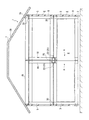
以下、本発明の一実施形態を図面に基づいて説明する。図1〜図9には本実施形態のユニット式建物1が示されている。図1,2には本実施の形態の全体構成が示されている。
図1,2に示すように、本実施形態のユニット式建物1は、基礎2の上に設けられた例えば4個の下階建物ユニット3からなる下階部4と、下階部4の下階建物ユニット3の上に載置された4個の上階建物ユニット5からなる上階部6と、この上階部6の上方に設けられる屋根部7とを備えて構成されている。なお、屋根部7は、小屋枠7Aとこの小屋枠7Aに支持される屋根パネル7Bとを含み構成されている。
Hereinafter, an embodiment of the present invention will be described with reference to the drawings. The unit type building 1 of this embodiment is shown by FIGS. 1 and 2 show the overall configuration of the present embodiment.
As shown in FIGS. 1 and 2, the unit type building 1 of the present embodiment includes a lower floor part 4 composed of, for example, four lower floor building units 3 provided on a foundation 2, and a lower floor part 4. The upper floor part 6 which consists of the four upper floor building units 5 mounted on the floor building unit 3 and the roof part 7 provided above this upper floor part 6 are comprised. The roof portion 7 includes a shed frame 7A and a roof panel 7B supported by the shed frame 7A.

以上の下階建物ユニット3及び上階建物ユニット5のうち、それぞれ2個ずつが、各建物ユニット3,5の短辺同士が対向する方向の一方向に隣り合うとともに、この一方向と交差する方向に所定間隔Lで離れて配置されている。
そして、4個の下階建物ユニット3は、後に詳細を述べるように、それぞれ1本の柱 が省略された柱省略コーナ部Aを有し、4個の上階建物ユニット5は、柱や梁が省略されていない通常の骨組みから構成されている。
Two each of the lower floor building unit 3 and the upper floor building unit 5 are adjacent to each other in one direction in which the short sides of the building units 3 and 5 face each other, and intersect with this one direction. They are spaced apart by a predetermined distance L in the direction.
As will be described in detail later, the four lower-floor building units 3 each have a column-omitted corner portion A in which one column is omitted. The four upper-floor building units 5 include columns and beams. Is composed of a normal skeleton that is not omitted.

以上の下階建物ユニット3及び上階建物ユニット5は、図3、図4に示す構成とされている。まず、図4に基づいて、上階建物ユニット5を説明する。
上階建物ユニット5は、四隅に立設される4本の柱10と、これらの柱10の上端間同士を結合する4本の天井梁11と、各柱10の下端間同士を結合する4本の床梁12とを含む骨組み13を有し、略直方体状に形成されている。
そして、天井梁11は各2本の長辺天井梁11A及び短辺天井梁11Bで構成され、床梁12は各2本の長辺床梁12A及び短辺床梁12Bで構成されている。2本の長辺天井梁11A間、及び2本の長辺床梁12A間には、図示しないが、複数本の天井小梁、複数本の根太がそれぞれ架け渡されている。また、柱10と天井梁11及び床梁12とは、仕口14を介して接続されている。
The above lower-floor building unit 3 and upper-floor building unit 5 are configured as shown in FIGS. First, the upper floor building unit 5 will be described with reference to FIG.
The upper-floor building unit 5 is composed of four pillars 10 erected at the four corners, four ceiling beams 11 that join the upper ends of these pillars 10, and four that join the lower ends of each pillar 10. It has a frame 13 including a floor beam 12 and is formed in a substantially rectangular parallelepiped shape.
The ceiling beam 11 is composed of two long-side ceiling beams 11A and short-side ceiling beams 11B, and the floor beam 12 is composed of two long-side floor beams 12A and short-side floor beams 12B. Although not shown, a plurality of ceiling beams and a plurality of joists are spanned between the two long-side ceiling beams 11A and between the two long-side floor beams 12A. In addition, the column 10, the ceiling beam 11, and the floor beam 12 are connected via a joint 14.

前記各下階建物ユニット3は、図3に示すように、3本の柱10と、これらの柱10の上端間同士を結合する4本の前記天井梁11と、各柱10の下端間同士を結合する4本の前記床梁12とを含む骨組み13Aを有し、略直方体状に形成されている。そして、1本の柱が省略された部位が柱省略コーナ部Aとされている。
なお、各下階建物ユニット3において、柱省略コーナ部Aには、輸送時や組み立て時等に下階建物ユニット3が変形しないように、仮柱10Aを設けてもよい。また、下階建物ユニット3において、前記上階建物ユニット5と同一部材には同一符号を付して、その詳細な説明は省略または簡略化している。
As shown in FIG. 3, each lower-floor building unit 3 includes three columns 10, four ceiling beams 11 that connect the upper ends of these columns 10, and the lower ends of the columns 10. The frame 13 </ b> A including the four floor beams 12 connecting the two is formed, and is formed in a substantially rectangular parallelepiped shape. A portion where one column is omitted is a column omitted corner portion A.
In each lower-floor building unit 3, a temporary pillar 10 </ b> A may be provided in the pillar omitted corner portion A so that the lower-floor building unit 3 is not deformed during transportation or assembly. Further, in the lower-floor building unit 3, the same members as those in the upper-floor building unit 5 are denoted by the same reference numerals, and detailed description thereof is omitted or simplified.

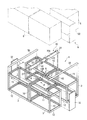
これらの4個の下階建物ユニット3は、図2、図5等に示すように、それぞれ柱省略コーナ部A同士を突き合わせるとともに、2個ずつが所定間隔Lあけて配置されている。そのため、下階部4には、4個の下階建物ユニット3により、柱なしの部分と所定間隔の隙間の部分とを合計した広さの大空間な居室Rが形成されるようになっている。
なお、一方向に隣り合う下階建物ユニット3,3は、構造は同じであるが勝手違いになっており、これらと所定間隔離れた下階建物ユニット3,3は、上記一方向に隣り合う下階建物ユニット3,3が180度向きを変えて配置された状態である。
また、所定間隔Lの寸法は、製作基準寸法であるモジュールが、例えば、1モジュール910mmである場合、本実施形態では、1/2モジュールの450mm程度に設定されている。ただし、この寸法は任意であるが、あまり小さいと間隔をあけた意味がなくなり、あまり大きいと建物の強度上の問題が生じる。
As shown in FIGS. 2, 5, and the like, these four lower-floor building units 3 abut each other on the column-omitted corner portions A and are arranged at a predetermined interval L. Therefore, in the lower floor portion 4, a large space room R having a total size of a portion without a pillar and a gap portion with a predetermined interval is formed by the four lower floor building units 3. Yes.
The lower-floor building units 3 and 3 that are adjacent in one direction have the same structure but are different from each other, and the lower-floor building units 3 and 3 that are separated from each other by a predetermined distance are adjacent to each other in the one direction. The lower-floor building units 3 and 3 are arranged in a 180-degree direction.
In addition, when the module that is the production standard dimension is, for example, 910 mm per module, the dimension of the predetermined interval L is set to about 450 mm of 1/2 module in this embodiment. However, this dimension is arbitrary, but if it is too small, there is no point in separating the space, and if it is too large, there will be a problem in the strength of the building.

以上のような一方向に隣り合う下階建物ユニット3間には、当該下階建物ユニット3に挟まれて補強梁20が設けられている。この補強梁20は、柱省略コーナ部Aに臨む各下階建物ユニット3の特に短辺天井梁11Bを補強するために設けられたものであり、所定間隔Lをあけて配置した2個の下階建物ユニット3に渡って設けられている。   Between the lower-floor building units 3 adjacent in one direction as described above, the reinforcing beam 20 is provided between the lower-floor building units 3. The reinforcing beams 20 are provided to reinforce the short-side ceiling beams 11B of the lower-floor building units 3 facing the corners A where the column is omitted. It is provided across the floor building unit 3.

補強梁20は、図5に示すように、所定厚さの板部材で形成されるとともに、下階建物ユニット3の天井梁11と上階建物ユニット5の床梁12との高さ寸法を合計した寸法とほぼ等しい高さ寸法に形成されている。このような補強梁20は、一端部を下階建物ユニット3の天井梁11の下端部に揃え、他端部を上階建物ユニット5側に突出させて取り付けられている。   As shown in FIG. 5, the reinforcing beam 20 is formed of a plate member having a predetermined thickness, and the height dimension of the ceiling beam 11 of the lower floor building unit 3 and the floor beam 12 of the upper floor building unit 5 is totaled. The height is approximately equal to the measured dimension. Such a reinforcing beam 20 is attached so that one end thereof is aligned with the lower end of the ceiling beam 11 of the lower floor building unit 3 and the other end protrudes toward the upper floor building unit 5 side.

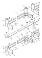
また、図6、7及び8に詳細を示したように、補強梁20は梁本体20Aを備え、この梁本体20Aの長さ方向両端部には、それぞれ梁本体20Aに沿って水平に設けられた補強プレート21が設けられ、梁本体20Aの長さ方向中央部にはコ字状の梁側突起22が2箇所設けられている。これらの補強プレート21及び梁側突起22は、それぞれ補強梁20の厚さ方向両側に設けられている。
補強プレート21は平面が略正方形状に形成されており、この平面は仕口14の上面と略同じ面積とされている。
梁側突起22は上下対の水平部22Aと鉛直部22Bとを有するコ字状部材と、この鉛直部22Bの中央から水平部22Aとは反対方向へ水平に延びたプレート部22Cとを備えている。そして、長さ方向両端部の補強プレート21は、一方向に隣り合う下階建物ユニット3における外側の各柱10の頂部を構成する仕口14同士を連結するようになっている。
Further, as shown in detail in FIGS. 6, 7 and 8, the reinforcing beam 20 includes a beam body 20A, and the beam body 20A is provided horizontally at both ends in the longitudinal direction along the beam body 20A. A reinforcing plate 21 is provided, and two U-shaped beam-side protrusions 22 are provided at the center in the length direction of the beam main body 20A. The reinforcing plate 21 and the beam-side protrusion 22 are provided on both sides in the thickness direction of the reinforcing beam 20, respectively.
The reinforcing plate 21 has a substantially square plane, and this plane has substantially the same area as the upper surface of the joint 14.
The beam-side protrusion 22 includes a U-shaped member having a pair of upper and lower horizontal portions 22A and a vertical portion 22B, and a plate portion 22C extending horizontally from the center of the vertical portion 22B in the opposite direction to the horizontal portion 22A. Yes. The reinforcing plates 21 at both ends in the length direction connect the joints 14 constituting the tops of the respective outer pillars 10 in the lower-floor building unit 3 adjacent in one direction.

梁側突起22は、一方向に隣り合い、かつ、所定間隔L離れた下階建物ユニット3における各柱省略コーナ部Aの仕口14同士を連結するようになっている。
具体的には、梁側突起22の水平部22A及び鉛直部22Bは、その端部が垂直に溶接で接合されることでコ字状に形成されている。また、ユニット側突起14Bは下階建物ユニット3の仕口14の側面に溶接で接合されている。
そして、鉛直部22Bは、建物ユニット3,5のそれぞれのユニット側突起14Bが設けられている仕口14の垂直面に当接されている。さらに、鉛直部22Bの長さ、つまり上下対の水平部22A幅寸法は、上下に対向する建物ユニット3,5のそれぞれのユニット側突起14Bの幅寸法と略同じである。
The beam-side protrusion 22 connects the joints 14 of the respective column omitted corner portions A in the lower-floor building unit 3 that are adjacent in one direction and separated by a predetermined distance L.
Specifically, the horizontal portion 22A and the vertical portion 22B of the beam-side protrusion 22 are formed in a U shape by joining their end portions vertically by welding. The unit-side protrusion 14B is joined to the side surface of the joint 14 of the lower-floor building unit 3 by welding.
And the vertical part 22B is contact | abutted to the vertical surface of the joint 14 in which each unit side protrusion 14B of the building units 3 and 5 is provided. Further, the length of the vertical portion 22B, that is, the width dimension of the pair of upper and lower horizontal parts 22A is substantially the same as the width dimension of the unit-side protrusion 14B of each of the building units 3 and 5 facing vertically.

上下対の水平部22Aは、下階建物ユニット3の柱省略コーナ部Aの仕口14の側面から突出したユニット側突起14Bに下側から当接され、これと同様に上側の水平部22Aが上建物ユニット5のユニット側突起14Bに上側から当接されている。
すなわち、柱10の頂部及び柱省略コーナ部Aの仕口14の上端部には、係合ピン15,16が立設され、この係合ピン15,16に隣接してボルト結合用孔14Aがあけられており、ユニット側突起14Bには、ボルト結合用孔14Cがあけられている。これに対して、補強プレート21及び梁側突起22には、係合孔21A,21B、及び係合孔22G,22Eがあけられ、さらに、ボルト結合用孔21C,22D,22Fがあけられている。
そのため、まず、それぞれ、柱10の頂部及び柱省略コーナ部Aの仕口14の上端部に立設された係合ピン15,16に、補強プレート21及び梁側突起22にあけられた係合孔21A,21B、及び係合孔22G,22Eをそれぞれ差し込み、その後、下階建物ユニット3の仕口14のボルト結合用孔14Aとプレート部22Cのボルト結合用孔22Fとに図示しないボルトを挿通させるとともに、このボルトに図示しないナットを螺合させて、プレート部22Cと仕口14の水平面とを上下方向に挟み込んで固定し、さらに、仕口14から突出したユニット側突起14Bにあけられたボルト結合用孔14Cと梁側突起22にあけられたボルト結合用孔22Dとに図示しないボルトを挿通させるとともに、このボルトに図示しないナットを螺合させて、梁側突起22とユニット側突起14Bとを上下方向に挟み込んで固定し、補強梁20、補強プレート21及び梁側突起22と、下階建物ユニット3とを位置決めして連結できるようになっている。
The pair of upper and lower horizontal portions 22A are in contact with the unit side protrusion 14B protruding from the side surface of the joint 14 of the column omitting corner portion A of the lower floor building unit 3 from the lower side. It abuts on the unit-side protrusion 14B of the upper building unit 5 from above.
That is, the engagement pins 15 and 16 are erected on the top of the column 10 and the upper end portion of the joint 14 of the column omitted corner portion A, and the bolt coupling hole 14A is adjacent to the engagement pins 15 and 16. The unit-side protrusion 14B has a bolt coupling hole 14C. On the other hand, the reinforcing plate 21 and the beam-side protrusion 22 are provided with engagement holes 21A and 21B and engagement holes 22G and 22E, and further, bolt connection holes 21C, 22D and 22F are formed. .
Therefore, first, the engagement pins 15 and 16 that are erected at the top of the column 10 and the upper end of the joint 14 of the column-omitted corner portion A are respectively engaged with the reinforcing plate 21 and the beam-side protrusion 22. The holes 21A and 21B and the engagement holes 22G and 22E are inserted, and then bolts (not shown) are inserted into the bolt connection holes 14A of the joint 14 of the lower floor building unit 3 and the bolt connection holes 22F of the plate portion 22C. At the same time, a nut (not shown) is screwed to the bolt to sandwich and fix the plate portion 22C and the horizontal surface of the joint 14 in the vertical direction, and is further opened in the unit-side protrusion 14B protruding from the joint 14. A bolt (not shown) is inserted into the bolt connection hole 14C and the bolt connection hole 22D formed in the beam-side protrusion 22, and a nut (not shown) is inserted into the bolt. The beam-side protrusion 22 and the unit-side protrusion 14B are sandwiched and fixed in the vertical direction so that the reinforcing beam 20, the reinforcing plate 21, the beam-side protrusion 22 and the lower floor building unit 3 can be positioned and connected. It has become.

上階建物ユニット5を連結、固定するには、まず、上階建物ユニット5における柱10の下端の仕口14にあけられた図示しない係合孔を前記係合ピン15,16に係合させて位置決めする。
その後、上階建物ユニット5及び下階建物ユニット3の仕口14にあけられたボルト結合用孔14Aと補強プレート21のボルト結合用孔21C及び梁側突起22にあけられたボルト結合用孔22Fに図示しないボルトを挿通させるとともに、上階建物ユニット5のユニット側突起14Bにあけられたボルト結合用孔14Cと水平部22Aにあけられたボルト結合用孔22Dにボルトを挿通させる。
そして、これらの図示しないボルトに図示しないナットを螺合させて、補強梁20を水平方向に挟み込み、補強プレート21及び梁側突起22を上下方向に挟み込んで、上階建物ユニット5と下階建物ユニット3とを連結、固定する。
この結果、上下に各4個の建物ユニット3,5が、補強プレート21及び梁側突起22と一体となった補強梁20によって互いに連結され、ユニット式建物1の全体の強度が確保されるようになっている。
In order to connect and fix the upper floor building unit 5, first, an engagement hole (not shown) formed in the joint 14 at the lower end of the column 10 in the upper floor building unit 5 is engaged with the engagement pins 15 and 16. Position.
Thereafter, the bolt coupling hole 14A opened in the joint 14 of the upper floor building unit 5 and the lower floor building unit 3, the bolt coupling hole 21C of the reinforcing plate 21, and the bolt coupling hole 22F opened in the beam side projection 22. A bolt (not shown) is inserted through the bolt, and a bolt is inserted through a bolt coupling hole 14C formed in the unit-side protrusion 14B of the upper floor building unit 5 and a bolt coupling hole 22D formed in the horizontal portion 22A.
Then, a nut (not shown) is screwed into these bolts (not shown), the reinforcing beam 20 is sandwiched in the horizontal direction, and the reinforcing plate 21 and the beam-side protrusion 22 are sandwiched in the vertical direction. Connect and fix the unit 3.
As a result, the four building units 3 and 5 above and below are connected to each other by the reinforcing beam 20 integrated with the reinforcing plate 21 and the beam-side protrusion 22 so that the overall strength of the unit building 1 is ensured. It has become.

4個の下階建物ユニット3の外周部分には、図5,9等に示すように、前記補強梁20とほぼ平行に外周用補強梁30が架設されている。この外周用補強梁30は板状部材で形成され、補強梁20とほぼ同じ長さ寸法に形成されている。   As shown in FIGS. 5, 9, etc., outer peripheral reinforcing beams 30 are installed on the outer peripheral portions of the four lower floor building units 3 substantially in parallel with the reinforcing beams 20. The outer circumferential reinforcing beam 30 is formed of a plate-like member and is formed to have substantially the same length as the reinforcing beam 20.

外周用補強梁30には、その両端部及び中央部に、係合孔30A,30B、及びボルト結合用孔30Cがそれぞれあけられており、柱10の頂部の仕口14に立設された係合ピン15,16に、外周用補強梁30の係合孔30A,30Bをそれぞれ差し込み、外周用補強梁30と、下階建物ユニット3とを位置決めして連結できるようになっている。
その後は、上階建物ユニット5及び下階建物ユニット3の仕口14のボルト結合用孔14Aと、外周用補強梁30のボルト結合用孔30Cにボルト17を挿通させるとともに、このボルト17にナット18を螺合させて、外周用補強梁30を水平方向に挟み込んで、上階建物ユニット5と下階建物ユニット3とを連結、固定できるようになっている。
Engagement holes 30A, 30B and bolt coupling holes 30C are formed in both ends and the center of the outer circumferential reinforcing beam 30, respectively. The engagement holes 30A and 30B of the outer periphery reinforcing beam 30 are inserted into the joint pins 15 and 16, respectively, so that the outer periphery reinforcing beam 30 and the lower floor building unit 3 can be positioned and connected.
Thereafter, the bolt 17 is inserted into the bolt coupling hole 14A of the joint 14 of the upper floor building unit 5 and the lower floor building unit 3 and the bolt coupling hole 30C of the outer peripheral reinforcing beam 30, and the nut 17 is inserted into the bolt 17. The upper floor building unit 5 and the lower floor building unit 3 can be connected and fixed by screwing 18 together and sandwiching the outer periphery reinforcing beam 30 in the horizontal direction.

前記所定間隔Lで離し置きされた下階建物ユニット3間の隙間は、図5,7に示すように、閉塞用パネルである壁パネル32で塞がれている。この壁パネル32には、下階建物ユニット3の外壁8(図2参照)と垂直面内で連続するように、図示しない接続用外壁が取り付けされるようになっている。
また、所定間隔Lで離し置きされた下階建物ユニット3間の上部の隙間は、閉塞用パネルである天井パネル33(図1参照)で塞がれている。
As shown in FIGS. 5 and 7, the gap between the lower-floor building units 3 spaced apart at the predetermined interval L is closed by a wall panel 32 that is a closing panel. A connection outer wall (not shown) is attached to the wall panel 32 so as to be continuous with the outer wall 8 (see FIG. 2) of the lower-floor building unit 3 in a vertical plane.
Further, the upper gap between the lower-floor building units 3 spaced apart by a predetermined interval L is closed by a ceiling panel 33 (see FIG. 1) that is a closing panel.

以上のように、4個の下階建物ユニット3のうち2個ずつを一方向に隣合わせるとともに、所定間隔Lの隙間をあけて配置し、4個の下階建物ユニット3の各柱省略コーナ部Aを一箇所に集めたので、図2に示すように、柱なし空間と所定間隔Lの隙間とでなる水平方向に連続する大空間の居室Rを形成することができる。   As described above, two of the four lower-floor building units 3 are adjacent to each other in one direction, and are arranged with a gap of a predetermined interval L, so that each of the four lower-floor building units 3 has a pillar omitted corner. Since the part A is collected in one place, as shown in FIG. 2, a large space room R which is formed by a columnless space and a gap having a predetermined interval L can be formed.

このような4個の下階建物ユニット3の上端には、前述のように、それぞれ上階建物ユニット5が載置されている。これらの上階建物ユニット5間の隙間は、図1に示すように、下階建物ユニット3間の隙間と同様に、閉塞用パネルである壁パネル32で塞がれている。また、離し置きされた上階建物ユニット5の下面の隙間及び上面の隙間は、図示しないが、例えば接続用床パネル、接続用天井パネルで、それぞれ塞がれている。
また、4個の上階建物ユニット5の上端面は、図2に示すように、一方向に隣り合う上階建物ユニット5の柱10同士を連結する上階用としての前記補強梁20で連結され、各上階建物ユニット5の外側外周は、上階用としての前記外周用補強梁30で連結されている。
As described above, the upper floor building units 5 are placed on the upper ends of the four lower floor building units 3 as described above. As shown in FIG. 1, the gaps between these upper-floor building units 5 are closed by wall panels 32 that are blocking panels, as are the gaps between the lower-floor building units 3. Further, although not shown, the gap between the lower surface and the upper surface of the upper floor building unit 5 placed separately is closed by, for example, a connection floor panel and a connection ceiling panel.
Further, as shown in FIG. 2, the upper end surfaces of the four upper floor building units 5 are connected by the reinforcing beams 20 for connecting the upper floor building units 5 adjacent to each other in one direction. The outer periphery of each upper floor building unit 5 is connected by the outer periphery reinforcing beam 30 for the upper floor.

図10に示すように、4個の上階建物ユニット5Aは、それぞれ柱省略コーナ部A同士を突き合わせるとともに、2個ずつが所定間隔Lあけて配置されている。
それぞれ柱省略コーナ部Aを有する1個の上階建物ユニット5Aが、一方向に隣り合って設けられるとともに、これらの上階建物ユニット5Aと直交する方向に、所定間隔Lをあけて、他の2個の上階建物ユニット5Aが離し置きされている。
As shown in FIG. 10, the four upper building units 5 </ b> A abut each of the column-omitted corner portions A and are arranged at a predetermined interval L.
One upper-floor building unit 5A, each having a column-omitted corner portion A, is provided adjacent to one direction, and is spaced apart by a predetermined interval L in a direction orthogonal to these upper-floor building units 5A. Two upper building units 5A are placed apart.

上階建物ユニット5Aのうち長辺方向に隣り合う2個は、前記第1実施形態の図3に示す建物ユニット3からユニット側突起14Bを省略したものが向きを変えて用いられ、また、他の2個は、勝手違いのものが用いられる。
すなわち、上階建物ユニット5Aは、4本の柱10のうち1本を省略して形成された柱省略コーナ部Aを備えて構成されている。
なお、柱省略コーナ部Aには、輸送用、組み立て用のために、仮柱10Aを設けてもよい。
Two of the upper floor building units 5A adjacent to each other in the long side direction are used by changing the orientation of the building unit 3 shown in FIG. 3 of the first embodiment except that the unit side protrusion 14B is omitted. The two are used in different ways.
That is, the upper floor building unit 5 </ b> A includes a column omitted corner portion A formed by omitting one of the four columns 10.
The column omitting corner portion A may be provided with a temporary column 10A for transportation and assembly.

以上のような4個の上階建物ユニット5Aのうち、一方向に隣り合う2個の上階建物ユニット5Aには、これらの上階建物ユニット5Aと対向配置された上階建物ユニット5Aに渡って補強用連結梁200が架け渡されている。この補強用連結梁200は特開2005−240358で示される補強梁と同じ構造である。   Of the four upper-floor building units 5A as described above, two upper-floor building units 5A adjacent to each other in one direction cross over the upper-floor building units 5A disposed opposite to the upper-floor building units 5A. The reinforcing connecting beam 200 is bridged. The reinforcing connecting beam 200 has the same structure as the reinforcing beam shown in Japanese Patent Application Laid-Open No. 2005-240358.

上階建物ユニット5Aの上方には、屋根部7を構成する小屋枠7Aが載置されている。この小屋枠7Aは、平面コ字状に形成されており、このような小屋枠7Aに、図示しない屋根パネル受けブラケットを介して屋根パネル7Bが取り付けられ、これらにより、前記屋根部7が構成されている(図2参照)。   Above the upper floor building unit 5A, a shed frame 7A constituting the roof portion 7 is placed. The shed frame 7A is formed in a plane U-shape, and the roof panel 7B is attached to the shed frame 7A via a roof panel receiving bracket (not shown), thereby forming the roof portion 7. (See FIG. 2).

以上のような第1実施形態によれば、次のような効果が得られる。
(1)4個の下階建物ユニット3が、各下階建物ユニット3の柱省略コーナ部Aを突き合わせて配置されており、しかも、一方向に隣り合う2個の下階建物ユニット3と所定間隔L離れて別の2個の下階建物ユニット3が配置されているので、4個の下階建物ユニット3で、柱なしで形成される空間と、所定間隔分だけ広くなった空間とを合計した大空間の居室Rを得ることができる。その結果、従来と同じ大きさ及び同じ数の建物ユニットでより広い居室空間を形成できる。
According to the first embodiment as described above, the following effects can be obtained.
(1) The four lower-floor building units 3 are arranged so as to face the pillar-omitted corner portions A of the respective lower-floor building units 3, and in addition to the two lower-floor building units 3 that are adjacent in one direction. Since another two lower-floor building units 3 are spaced apart by an interval L, the four lower-floor building units 3 have a space formed without pillars and a space widened by a predetermined interval. A large room R can be obtained. As a result, a larger room space can be formed with the same size and the same number of building units as in the past.

(2)4個の下階建物ユニット3が、各下階建物ユニット3の柱省略コーナ部Aを突き合わせ、また、2個ずつが所定間隔L離れて配置されているが、一方向に隣り合う下階建物ユニット3間に補強梁20が架け渡され、この補強梁20には、隣り合う下階建物ユニット3の柱10の頂部間を連結する水平な補強プレート21と、隣り合う下階建物ユニット3の柱10の頂部に設けられたユニット側突起14Bと高い剛度で接合する梁側突起22とが設けられているので、柱省略コーナ部Aを有する下階建物ユニット3同士を補強することができる。その結果、ユニット式建物1の強度を従来よりも大きなものにすることができる。 (2) Four lower-floor building units 3 abut each other on the pillar-omitted corner portion A of each lower-floor building unit 3, and two are arranged at a predetermined distance L, but are adjacent in one direction. Reinforcing beams 20 are bridged between the lower-floor building units 3, and the horizontal reinforcing plates 21 that connect the tops of the pillars 10 of the adjacent lower-floor building units 3 and the adjacent lower-floor buildings are connected to the reinforcing beams 20. Since the unit-side projection 14B provided on the top of the column 10 of the unit 3 and the beam-side projection 22 joined with high rigidity are provided, the lower-floor building units 3 having the column-omitted corner portion A are reinforced. Can do. As a result, the strength of the unit type building 1 can be made larger than before.

(3)仕口14から突出したユニット側突起14Bは水平に延びて形成されているので、このユニット側突起14Bに梁側突起22の水平部22Aを載置することができる。
このため、補強梁20の設置工事の際、補強梁20を容易に仮置きすることができ、ユニット側突起14Bと梁側突起22とを容易に高い剛度で接合することができ、補強梁20の設置工事を容易に行うことができる。
(3) Since the unit-side protrusion 14B protruding from the joint 14 extends horizontally, the horizontal portion 22A of the beam-side protrusion 22 can be placed on the unit-side protrusion 14B.
For this reason, during the installation work of the reinforcing beam 20, the reinforcing beam 20 can be temporarily placed, and the unit-side protrusion 14B and the beam-side protrusion 22 can be easily joined with high rigidity. Can be installed easily.

(4)梁側突起22は、上下対の水平部22Aと鉛直部22Bとは、その端部が垂直に溶接で接合されることでコ字状に形成されている。
このため、上下対の水平部22Aとユニット側突起14Bとが当接することに加えて、鉛直部22Bと仕口14の接合されている垂直面とが当接することで、水平方向と垂直方向とに補強ができるので、建物ユニット3,5と補強梁20との補強をより大きなものにすることができる。
(4) The beam-side protrusion 22 is formed in a U shape by vertically joining the horizontal portion 22A and the vertical portion 22B of the upper and lower pairs by welding.
For this reason, in addition to the upper and lower horizontal portions 22A and the unit-side protrusion 14B being in contact, the vertical portion 22B and the vertical surface to which the joint 14 is bonded are in contact with each other. Therefore, the reinforcement between the building units 3 and 5 and the reinforcing beam 20 can be made larger.

(5)梁側突起22は、鉛直部22Bの中央から水平部22Aとは反対方向へ水平に延びたプレート部22Cを備えている。
このため、プレート部22Cは、上下建物ユニット3,5に挟まれるので、ユニット側突起14Bを有するそれぞれの仕口14から延びる短辺天井梁11Bの上面と短辺床梁12Bの底面とに当接することができるから、建物ユニット3,5と補強梁20との補強をさらに大きなものにすることができる。
(5) The beam-side protrusion 22 includes a plate portion 22C that extends horizontally from the center of the vertical portion 22B in the direction opposite to the horizontal portion 22A.
For this reason, since the plate portion 22C is sandwiched between the upper and lower building units 3 and 5, it contacts the upper surface of the short-side ceiling beam 11B and the bottom surface of the short-side floor beam 12B extending from the respective joints 14 having the unit-side protrusion 14B. Therefore, the reinforcement between the building units 3 and 5 and the reinforcing beam 20 can be further increased.

なお、本発明は前述の各実施形態に限定されるものではなく、本発明の目的を達成できる範囲での変形、改良等は本発明に含まれるものである。
例えば、前記実施形態では、補強梁20が、所定厚さの板状部材で形成されているが、これに限らない。例えば、断面矩形状の角パイプを用いてもよい。このような実施形態では、角パイプの厚さを適宜大きくすることで、板状部材よりその差の分だけでも居室面積を大きくすることができる。
The present invention is not limited to the above-described embodiments, and modifications, improvements, and the like within the scope that can achieve the object of the present invention are included in the present invention.
For example, in the above-described embodiment, the reinforcing beam 20 is formed of a plate-like member having a predetermined thickness, but the present invention is not limited to this. For example, a square pipe having a rectangular cross section may be used. In such an embodiment, by appropriately increasing the thickness of the square pipe, the living room area can be increased by the difference from the plate member.

前記実施形態では梁側突起22は、コ字状の部材を有していたがこれに限らない。例えば、鉛直部22Bと上側若しくは下側のいずれかに水平部22Aとを有するL字状の部材としてもよい。   In the above embodiment, the beam-side protrusion 22 has a U-shaped member, but is not limited thereto. For example, an L-shaped member having a vertical portion 22B and a horizontal portion 22A on either the upper side or the lower side may be used.

前記実施形態では外周用補強梁30は、板状部材で形成され、補強梁20とほぼ同じ長さ寸法としていたがこれに限らない。例えば、所定間隔L離し置かれた建物ユニット3の対向する仕口14を連結する板状部材としてもよい。   In the above-described embodiment, the outer circumferential reinforcing beam 30 is formed of a plate-like member and has substantially the same length as the reinforcing beam 20, but is not limited thereto. For example, it is good also as a plate-shaped member which connects the connection mouth 14 which the building unit 3 placed at predetermined intervals L apart.

本発明は、個人住宅用に利用できる他、アパート等共同住宅にも利用することができる。   The present invention can be used not only for private houses but also for apartment houses such as apartments.

本発明に係るユニット式建物の第1実施形態を示す全体図。1 is an overall view showing a first embodiment of a unit building according to the present invention. 前記実施形態のユニット式建物を示す全体縦断面図。The whole longitudinal section showing the unit type building of the embodiment. 前記実施形態の柱省略部を有する建物ユニットを示す全体斜視図。The whole perspective view which shows the building unit which has the pillar omission part of the said embodiment. 前記実施形態の通常の構成の建物ユニットを示す全体斜視図。The whole perspective view which shows the building unit of the normal structure of the said embodiment. 前記実施形態のユニット式建物の下階部を示す全体斜視図。The whole perspective view which shows the lower floor part of the unit type building of the said embodiment. 図5におけるVI−VI線に沿った断面図。Sectional drawing along the VI-VI line in FIG. 前記実施形態の下階部及び上階部を示す分解斜視図。The disassembled perspective view which shows the lower floor part and the upper floor part of the said embodiment. 前記実施形態の要部を示す分解斜視図。The disassembled perspective view which shows the principal part of the said embodiment. 前記実施形態の他の要部を示す分解斜視図。The disassembled perspective view which shows the other principal part of the said embodiment. 前記実施形態の2階部分を示す斜視図。The perspective view which shows the 2nd floor part of the said embodiment.

符号の説明Explanation of symbols

1,1A…ユニット式建物
3…下階建物ユニット
4…下階部
5…上階建物ユニット
6…上階部
10…柱
11…天井梁
11A…長辺天井梁
11B…短辺天井梁
12…床梁
12A…長辺床梁
12B…短辺床梁
13,13A…骨組み
14B…ユニット側突起
20…補強梁
20A…梁本体
21…補強プレート
22…梁側突起
22A…水平部
22B…鉛直部
30…外周用補強梁
32…閉塞用パネルである壁パネル
A…柱省略コーナ部
1,1A ... Unit type building
3 ... Lower floor building unit
4 ... Lower floor
5… Upstairs building unit
6 ... Upper floor 10 ... Column 11 ... Ceiling beam 11A ... Long-side ceiling beam 11B ... Short-side ceiling beam 12 ... Floor beam 12A ... Long-side floor beam 12B ... Short-side floor beam 13, 13A ... Frame 14B ... Unit side projection DESCRIPTION OF SYMBOLS 20 ... Reinforcement beam 20A ... Beam main body 21 ... Reinforcement plate 22 ... Beam side protrusion 22A ... Horizontal part 22B ... Vertical part 30 ... Reinforcement beam for outer periphery 32 ... Wall panel which is a panel for closure
A ... Pole omitted corner

Claims (3)

柱及び梁から略直方体状の骨組みを有し1本の柱が省略された建物ユニットを離し置きして大空間を形成するとともにこれらの建物ユニットの間を補強梁で補強するユニット式建物であって、前記補強梁は、隣り合う建物ユニットの少なくとも離し置きした部分に配置される梁本体と、前記骨組みの側面に突出して設けられるユニット側突起に連結固定される梁側突起とを備え、前記梁側突起は前記梁本体の長手方向に沿った水平部と前記水平部に一体に形成された鉛直部とを備え、かつ、前記ユニット側突起に高い剛度で接合されることを特徴とするユニット式建物。 It is a unit type building in which a large space is formed by separating a building unit that has a substantially rectangular parallelepiped frame from a column and a beam, and one column is omitted, and between these building units is reinforced with a reinforcing beam. The reinforcing beam includes a beam main body disposed at least in a part of the building unit adjacent to each other, and a beam side protrusion connected and fixed to a unit side protrusion protruding from a side surface of the frame, The beam-side projection includes a horizontal portion along the longitudinal direction of the beam main body and a vertical portion formed integrally with the horizontal portion, and is joined to the unit-side projection with high rigidity. Ceremony building. 請求項1に記載のユニット式建物であって、前記ユニット側突起は水平に延びて形成されており、前記梁側突起は水平部が前記ユニット側突起と接合されることを特徴とするユニット式建物。 The unit type building according to claim 1, wherein the unit side protrusion is formed to extend horizontally, and the beam side protrusion has a horizontal portion joined to the unit side protrusion. building. 請求項1または請求項2に記載のユニット式建物であって、前記ユニット式建物は下階建物ユニットと上階建物ユニットとを備え、前記下階建物ユニットの上方側面に前記ユニット側突起を設け、前記上階建物ユニットの下方側面に前記ユニット側突起を設け、前記梁側突起は、前記上下のユニット側突起にそれぞれ接合される水平部と、これらの水平部の端部に連結された鉛直部とを備えたコ字状に形成されることを特徴とするユニット式建物。 The unit type building according to claim 1 or 2, wherein the unit type building includes a lower floor building unit and an upper floor building unit, and the unit side protrusion is provided on an upper side surface of the lower floor building unit. The unit-side protrusion is provided on the lower side surface of the upper-floor building unit, and the beam-side protrusion is connected to the upper and lower unit-side protrusions, respectively, and the vertical connected to the ends of these horizontal parts. A unit type building characterized by being formed in a U-shape with a section.
JP2008071741A 2008-03-19 2008-03-19 Unit building Expired - Fee Related JP5053137B2 (en)

Priority Applications (1)

Application Number Priority Date Filing Date Title
JP2008071741A JP5053137B2 (en) 2008-03-19 2008-03-19 Unit building

Applications Claiming Priority (1)

Application Number Priority Date Filing Date Title
JP2008071741A JP5053137B2 (en) 2008-03-19 2008-03-19 Unit building

Publications (2)

Publication Number Publication Date
JP2009228232A true JP2009228232A (en) 2009-10-08
JP5053137B2 JP5053137B2 (en) 2012-10-17

Family

ID=41243936

Family Applications (1)

Application Number Title Priority Date Filing Date
JP2008071741A Expired - Fee Related JP5053137B2 (en) 2008-03-19 2008-03-19 Unit building

Country Status (1)

Country Link
JP (1) JP5053137B2 (en)

Cited By (2)

* Cited by examiner, † Cited by third party
Publication number Priority date Publication date Assignee Title
JP2016017351A (en) * 2014-07-09 2016-02-01 パナソニックIpマネジメント株式会社 Building unit and building
CN106948483A (en) * 2017-04-29 2017-07-14 天津大学 A kind of connecting node applied to modularization steel building

Citations (4)

* Cited by examiner, † Cited by third party
Publication number Priority date Publication date Assignee Title
JPH1061020A (en) * 1996-08-23 1998-03-03 Sekisui Chem Co Ltd Unit building and construction method thereof
JP2005240358A (en) * 2004-02-25 2005-09-08 Misawa Homes Co Ltd Unit building
JP2006070659A (en) * 2004-09-06 2006-03-16 Misawa Homes Co Ltd Connecting structure for building units
JP2007146556A (en) * 2005-11-29 2007-06-14 Toyota Motor Corp Unit building

Patent Citations (4)

* Cited by examiner, † Cited by third party
Publication number Priority date Publication date Assignee Title
JPH1061020A (en) * 1996-08-23 1998-03-03 Sekisui Chem Co Ltd Unit building and construction method thereof
JP2005240358A (en) * 2004-02-25 2005-09-08 Misawa Homes Co Ltd Unit building
JP2006070659A (en) * 2004-09-06 2006-03-16 Misawa Homes Co Ltd Connecting structure for building units
JP2007146556A (en) * 2005-11-29 2007-06-14 Toyota Motor Corp Unit building

Cited By (2)

* Cited by examiner, † Cited by third party
Publication number Priority date Publication date Assignee Title
JP2016017351A (en) * 2014-07-09 2016-02-01 パナソニックIpマネジメント株式会社 Building unit and building
CN106948483A (en) * 2017-04-29 2017-07-14 天津大学 A kind of connecting node applied to modularization steel building

Also Published As

Publication number Publication date
JP5053137B2 (en) 2012-10-17

Similar Documents

Publication Publication Date Title
JP5133738B2 (en) Unit type building and reinforcement member
JP5501571B2 (en) Connecting members and unit buildings
JP4583778B2 (en) Unit building
JP4503982B2 (en) Reinforced beams and unit buildings with the reinforced beams
JP5478864B2 (en) Connection structure, unit type building, construction method
JP5128313B2 (en) Unit building
JP5123603B2 (en) Unit type building and construction method of unit type building
JP5629147B2 (en) Unit building
JP5362333B2 (en) Unit building
JP5053137B2 (en) Unit building
JP5237575B2 (en) Unit building
JP5123602B2 (en) Unit type building and construction method of unit type building
JP2005240359A (en) Unit building and building unit
JP5312163B2 (en) Unit building
JP5501725B2 (en) Unit building
JP3887217B2 (en) Unit building
JP5362318B2 (en) Unit building
JP5599908B2 (en) building
JP2001295371A (en) Building unit and unit building with connected building unit
JP5000881B2 (en) Unit type building and construction method of the unit type building
JP5237744B2 (en) Building unit and unit type building
JP5342886B2 (en) Unit building
JP5280720B2 (en) Unit type building and construction method of unit type building
JP5362893B2 (en) Unit building
JP5421938B2 (en) Building opening structure

Legal Events

Date Code Title Description
A621 Written request for application examination

Free format text: JAPANESE INTERMEDIATE CODE: A621

Effective date: 20110127

A977 Report on retrieval

Free format text: JAPANESE INTERMEDIATE CODE: A971007

Effective date: 20120628

TRDD Decision of grant or rejection written
A01 Written decision to grant a patent or to grant a registration (utility model)

Free format text: JAPANESE INTERMEDIATE CODE: A01

Effective date: 20120703

A01 Written decision to grant a patent or to grant a registration (utility model)

Free format text: JAPANESE INTERMEDIATE CODE: A01

A61 First payment of annual fees (during grant procedure)

Free format text: JAPANESE INTERMEDIATE CODE: A61

Effective date: 20120725

R150 Certificate of patent or registration of utility model

Ref document number: 5053137

Country of ref document: JP

Free format text: JAPANESE INTERMEDIATE CODE: R150

Free format text: JAPANESE INTERMEDIATE CODE: R150

FPAY Renewal fee payment (event date is renewal date of database)

Free format text: PAYMENT UNTIL: 20150803

Year of fee payment: 3

LAPS Cancellation because of no payment of annual fees