JP2009201975A - Racing game apparatus - Google Patents
Racing game apparatus Download PDFInfo
- Publication number
- JP2009201975A JP2009201975A JP2008254965A JP2008254965A JP2009201975A JP 2009201975 A JP2009201975 A JP 2009201975A JP 2008254965 A JP2008254965 A JP 2008254965A JP 2008254965 A JP2008254965 A JP 2008254965A JP 2009201975 A JP2009201975 A JP 2009201975A
- Authority
- JP
- Japan
- Prior art keywords
- model
- horse
- traveling
- running
- shaft
- Prior art date
- Legal status (The legal status is an assumption and is not a legal conclusion. Google has not performed a legal analysis and makes no representation as to the accuracy of the status listed.)
- Withdrawn
Links
Images


Landscapes
- Toys (AREA)
Abstract
Description
本発明は、競馬、競輪、競艇、自動車レースなどを模した競走ゲーム装置に関し、特に、馬、自転車、船、自動車などの形状を付与した模型体を搭載した複数の走行体による競走ゲームが実行される競走ゲーム装置に関する。 The present invention relates to a racing game apparatus simulating horse racing, bicycle racing, boat racing, car racing, and the like, and in particular, a racing game is executed by a plurality of running bodies equipped with a model body having a shape such as a horse, bicycle, ship, or car. The present invention relates to a racing game apparatus.
複数の走行体が配置される走行面と、当該走行面の下方に敷設された複数の自走体が配置される第2走行面を備え、競走馬の前後脚や騎手の手足を揺動させることができる模型体を搭載した複数の走行体が上記走行面上を走行し、走行面の周囲に配置された操作盤(サテライト)からメダルなどの遊戯媒体を投入することで、走行体の順位等についての投票を行うことができる競走ゲーム装置が知られている(特許文献1)。 A traveling surface on which a plurality of traveling bodies are arranged and a second traveling surface on which a plurality of self-propelled bodies laid below the traveling surface are disposed, and swings the front and rear legs of the racehorse and the jockey's limbs A plurality of traveling bodies equipped with a model body that can be run on the above-mentioned traveling surface, and a game medium such as a medal is inserted from an operation panel (satellite) arranged around the traveling surface. There is known a racing game apparatus that can perform voting on the like (Patent Document 1).
上記の競走ゲーム装置では、走行体を走行させ、模型体を動作させるための動力源や制御装置を第2走行面の自走体に搭載し、自走体及び走行体の双方に搭載した鉛直方向軸の周りに回転可能な磁石のカップリングによって自走体から走行体に動力を供給する方式が採用されており、これにより、動力源や制御装置などの設置にスペースを要する機材を走行体に搭載する必要を解消し、走行体のサイズをコンパクトに保ちつつ、模型体の造作や動作機構を精緻化することが可能とされている。 In the above-mentioned racing game apparatus, the power source and the control device for running the running body and operating the model body are mounted on the self-propelled body on the second traveling surface, and the vertical mounted on both the self-running body and the traveling body. A method of supplying power from the self-propelled body to the traveling body by coupling a magnet that can rotate around the direction axis is adopted, and this allows equipment that requires space to install a power source, a control device, etc. It is possible to eliminate the necessity of mounting on the vehicle and to refine the model structure and operation mechanism while keeping the size of the traveling body compact.
また、上記競走ゲーム装置では、操作盤に映像を表示できるモニタが設置されており、そのモニタ上において、競走ゲームで勝利した走行体や投票で多量の遊戯媒体の投入を受けた走行体に対応する競走馬や騎手が喜んだり、歓声に応えたりする映像を表示し、或いは、遊戯者が投票した走行体が勝利したときに賞賛や祝福のメッセージを表示するなど、競走ゲームの興趣性を高め、或いは、遊戯者の投票への意欲を刺激するための様々な演出表示が行われる。 In addition, in the above-mentioned racing game apparatus, a monitor capable of displaying an image on the operation panel is installed, and on the monitor, a running body that has won a racing game or a running body that has received a large amount of game media by voting is supported. Displaying images that make racehorses and jockeys happy or respond to cheers, or display a message of praise or congratulations when a runner voted by a player wins. Alternatively, various effects are displayed to stimulate the player's willingness to vote.
しかし、モニタ上の映像として表示される競走馬や騎手と走行体に搭載された模型体の間では外観や動作が一致しないことなどから、遊戯者が両者の対応を理解できずに上記演出の目的が達成されない場合があり、或いは、両者の外観や動作の不一致によって遊戯者に違和感や不自然な印象を与えてしまう場合もある。 However, since the appearance and operation do not match between the racehorses and jockeys displayed as video on the monitor and the model mounted on the traveling body, the player cannot understand the correspondence between the two and The purpose may not be achieved, or the player may feel uncomfortable or unnatural due to a mismatch in the appearance or operation of both.
従って、上記のような不都合を生じさせることなく、競走ゲームの興趣性を高め、或いは、遊戯者の投票への意欲を刺激し、高揚させるための新たな演出手法が必要とされていた。 Therefore, there has been a need for a new production technique for enhancing the interest of a racing game without stimulating the above-described disadvantages, or for stimulating and enhancing the player's willingness to vote.
また、特定の遊戯者が特定の走行体に多量の遊戯媒体を投入して投票を行った場合や、その特定の走行体が競走ゲームにおいて勝利した場合に、その特定の遊戯者の投票に対するレスポンスとしてその走行体上で何らかのアクションを行うことができれば、遊戯者の投票意欲を強く刺激することができると考えられるが、走行体上でのアクションがその遊戯者の投票に対するレスポンスであることを、遊戯者において理解可能なものとする具体的な手法は明らかではなかった。 In addition, when a specific player casts a large amount of game media into a specific runner and votes, or when the specific runner wins a race game, the response to the vote of the specific player If it is possible to perform some action on the running body, it is thought that the player's willingness to vote can be strongly stimulated, but that the action on the running body is a response to the player's vote, The specific method that can be understood by the player was not clear.
また、上記競走ゲーム装置では、上記モニタ上の表示によって、各走行体の現在の調子や過去の戦績などが投票のための参考情報として遊戯者に提供される場合があるが、現実に競走ゲームにおいて競走をするのは走行面上に配置された走行体であり、投票のための参考情報等を走行面上の走行体から直接遊戯者に提供できることが望ましい。 Further, in the above-described racing game device, the current condition of each traveling body, past battle record, and the like may be provided to the player as reference information for voting depending on the display on the monitor. It is desirable that the running body is a running body arranged on the running surface and can provide the player with reference information for voting directly from the running body on the running surface.
しかし、走行面上の走行体を用いて投票のための参考情報等を遊戯者に提供する具体的な方法は従来明らかとされてこなかった。
本発明は、上記状況に鑑みてなされたものであり、下記のいずれか一以上の目的を達成するものである。 The present invention has been made in view of the above situation, and achieves one or more of the following objects.
即ち、本発明の目的は、より迫力のある態様で、遊戯者に理解しやすい態様で、或いは、遊戯者に違和感を与えない態様で、競走ゲームの興趣性を高め、或いは、遊戯者の投票への意欲を刺激するなどを目的とする演出を行うことが可能な競走ゲーム装置を提供することにある。 In other words, the object of the present invention is to enhance the fun of a competitive game in a more powerful mode, in a mode that is easy for the player to understand, or in a mode that does not give the player a sense of incongruity, or the player's vote An object of the present invention is to provide a racing game apparatus capable of producing an effect aimed at stimulating motivation for the user.
本発明の他の目的は、競走ゲームにおける投票のための参考情報等を、走行面上の走行体を用いて遊戯者に直接提供することが可能な競走ゲーム装置を提供することにある。 Another object of the present invention is to provide a racing game apparatus capable of directly providing reference information for voting in a racing game to a player using a running body on a running surface.
本発明の更に他の目的は、鉛直方向の軸の周りで回転可能な磁石のカップリングにより、走行体が配置される走行面と平行な面内に敷設された第2走行面上の自走体から走行体に搭載した模型体を駆動するための動力が供給される競走ゲーム装置であって、自走体から走行体への動力の供給系統数を増加させることなく、より多様な態様で模型体を動作させることが可能な競走ゲーム装置を提供することにある。 Still another object of the present invention is to self-travel on a second traveling surface laid in a plane parallel to the traveling surface on which the traveling body is arranged by coupling of a magnet that can rotate around a vertical axis. A racing game apparatus in which power for driving a model mounted on a traveling body is supplied from the body in a more diverse manner without increasing the number of power supply systems from the traveling body to the traveling body An object of the present invention is to provide a racing game apparatus capable of operating a model body.
本発明は、上記問題を解決したものであり、
所定の走行面上を走行することが可能であり、少なくとも1の可動部材を有する模型体を搭載した複数の走行体と、
遊戯者の操作を受け付ける複数の操作盤と、
前記操作盤における操作に従って、前記走行体の順位についての投票を受け付ける投票受付手段とを備え、複数の前記走行体が前記走行面上を走行する競走ゲームが行われる競走ゲーム装置であって、
所定の条件が成立した場合に、前記可動部材を駆動して前記模型体を所定の態様で動作させる模型演出手段を更に備えることを特徴とする競走ゲーム装置(請求項1)である。
The present invention solves the above problems,
A plurality of traveling bodies mounted with a model body capable of traveling on a predetermined traveling surface and having at least one movable member;
A plurality of operation panels that accept player's operations;
In accordance with an operation on the operation panel, a voting accepting unit that receives a vote about the ranking of the traveling body, and a racing game device in which a racing game in which a plurality of the traveling bodies travel on the traveling surface is performed,
A race game device (Claim 1), further comprising model rendering means for driving the movable member to operate the model body in a predetermined manner when a predetermined condition is satisfied.
本発明では、所定の条件が成立した場合に、模型体の可動部材を駆動して模型体を所定の態様で動作させることが可能であるために、走行体に搭載した模型体を動作させることによって、競走ゲームの興趣性を高め、遊戯者の投票への意欲を高揚させるなどを目的とする演出を行うことが可能となり、或いは、走行体に搭載した模型体の動作によって投票のための参考情報等を遊戯者に直接提供することが可能になる。 In the present invention, when a predetermined condition is established, the model body mounted on the traveling body can be operated because the model body can be operated in a predetermined mode by driving the movable member of the model body. This makes it possible to enhance the fun of the racing game and enhance the player's willingness to vote, or for the purpose of voting based on the movement of the model mounted on the running body. It becomes possible to provide information directly to the player.
また、本発明では、モニタ上の映像による演出において生じていた映像と模型体の間での外観や動作の不一致の問題を生じないため、遊戯者に違和感や不自然な印象を与えることなく種々の演出を行うことが可能になる。 In addition, in the present invention, since there is no problem of disagreement in appearance and operation between the image and the model that has been produced in the presentation by the image on the monitor, various kinds of feelings are given without giving the player a sense of incongruity or unnaturalness. It becomes possible to perform.
本発明では、前記投票受付手段が受け付けた複数の前記操作盤での前記投票を集計する投票集計手段を更に備え、前記模型演出手段は、前記所定の条件が成立した場合に、前記集計の結果に従って決定される前記走行体に搭載された前記模型体を前記所定の態様で動作させるよう構成し(請求項2)、更には、前記投票受付手段は、所定の遊戯媒体を対価として前記投票を受け付け、前記模型演出手段は、前記複数の操作盤での前記投票において対価とされた遊戯媒体の多寡により決定される前記走行体に搭載された前記模型体を前記所定の態様で動作させるよう構成する(請求項3)ことが好ましい。 In the present invention, it further comprises voting counting means for counting the votes on the plurality of operation panels received by the voting receiving means, wherein the model rendering means is the result of the counting when the predetermined condition is satisfied. The model body mounted on the traveling body determined according to the above is configured to operate in the predetermined mode (Claim 2), and further, the voting accepting unit performs the voting with a predetermined game medium as a price. The model presentation means is configured to operate the model body mounted on the traveling body determined in accordance with the number of game media considered in the voting on the plurality of operation panels in the predetermined mode. (Claim 3) is preferable.
かかる発明では、多くの投票を受けた走行体や、投票において多くの遊戯媒体の投入を受けた走行体において模型体の動作演出を行うことにより、遊戯者に分かり易い態様で投票への意欲を高揚させるための演出を行うことが可能である。 In such an invention, by performing a motion effect of a model body on a traveling body that has received a lot of votes, or on a traveling body that has received a lot of play media in the voting, the player is motivated to vote in an easy-to-understand manner. It is possible to produce an effect to elevate.
本発明では、前記走行面に、前記複数の操作盤に割り当てられた複数の操作盤対応領域が設定され、前記模型演出手段は、特定の前記操作盤において所定の操作が行われた場合に、当該特定の操作盤に対応付けられた前記操作盤対応領域内において、前記走行体に搭載された前記模型体を前記所定の態様で動作させること(請求項4)が好ましい。 In the present invention, a plurality of operation panel corresponding areas assigned to the plurality of operation panels are set on the traveling surface, and the model rendering means is operated when a predetermined operation is performed on the specific operation panel. It is preferable that the model body mounted on the traveling body is operated in the predetermined manner within the operation panel corresponding area associated with the specific operation panel.
かかる発明では、操作盤と操作盤対応領域の対応関係が遊戯者に理解可能なように各操作盤に各操作盤対応領域を割り当てておけば、いずれかの操作盤対応領域に移動させた走行体上で模型体を動作させることにより、特定の操作盤或いはその操作盤を使用中の遊戯者のための演出であることを遊戯者が理解できる態様で模型体による演出を行うことが可能となる。 In such an invention, if each operation panel corresponding area is assigned to each operation panel so that the player can understand the correspondence between the operation panel and the operation panel corresponding area, the traveling moved to one of the operation panel corresponding areas. By operating the model body on the body, it is possible to perform the performance by the model body in a manner that allows the player to understand that the operation is for a specific operation panel or a player who is using the operation panel Become.
本発明では、前記模型演出手段は、特定の前記操作盤において特定の前記走行体に投票する操作が行われ、当該特定の走行体が前記競走ゲームにおいて勝利した場合に、当該特定の操作盤に対応付けられた前記操作盤対応領域内において、当該特定の走行体に搭載された前記模型体を前記所定の態様で動作させること(請求項5)が好ましい。 In the present invention, the model production means performs an operation for voting on the specific traveling body on the specific operation panel, and when the specific traveling body wins in the racing game, It is preferable that the model body mounted on the specific traveling body is operated in the predetermined manner within the associated operation panel corresponding area.
かかる発明では、遊戯者が投票した走行体が競走ゲームにおいて勝利した場合に、その投票が行われた操作盤或いはその操作盤を使用中の遊戯者を対象とした演出であることを遊戯者が理解できる態様で、その勝利した走行体に搭載された模型体による演出を行うことが可能である。 In such an invention, when a running body voted by a player wins in a racing game, the player indicates that the operation is performed on the operation panel on which the vote is performed or the player who is using the operation panel. In an understandable manner, it is possible to produce an effect by a model mounted on the winning traveling body.
本発明では、
前記走行体が、駆動軸と、前記駆動軸の回転力を前記可動部材に伝達することで前記可動部材を動作させる可動部材駆動機構とを更に備え、前記可動部材駆動機構は、前記駆動軸の回転方向が正方向である場合と逆方向である場合とで、前記可動部材を異なる態様で動作させること(請求項6)が好ましい。
In the present invention,
The traveling body further includes a drive shaft, and a movable member drive mechanism that operates the movable member by transmitting a rotational force of the drive shaft to the movable member, and the movable member drive mechanism It is preferable to operate the movable member in a different manner depending on whether the rotation direction is the forward direction or the reverse direction (Claim 6).
かかる発明では、例えば、動物の形状の模型体を搭載した走行体を走行させる競走ゲーム装置の場合であれば、駆動軸を正回転させることによって動物が走行している様子を模擬する態様で模型体を動作させ、駆動軸を逆回転させることによって遊戯者の投票意欲を刺激し、投票の参考情報を提供するなどを目的とした演出動作を模型体に行わせるなど、模型体を駆動するための駆動軸の数を増加させることなく、模型体の動作態様を多様化することが可能となる。 In this invention, for example, in the case of a racing game device that runs a running body equipped with a model body in the shape of an animal, the model simulates the state in which the animal is running by rotating the drive shaft forward. In order to drive the model body, for example, to stimulate the player's willingness to vote by rotating the drive shaft and reversely rotating the drive shaft, and for the model body to perform staging operations for the purpose of providing reference information for voting, etc. It is possible to diversify the operation mode of the model body without increasing the number of drive shafts.
なお、本明細書において「正方向」は、時計回り方向又は反時計回り方向の意味であり、「逆方向」は「正方向」とは反対の方向の意味である。 In this specification, “forward direction” means a clockwise direction or counterclockwise direction, and “reverse direction” means a direction opposite to the “forward direction”.
本発明では、前記競走ゲームにおいて走行するそれぞれの前記走行体について、前記競走ゲームの実行毎に変動する能力パラメータを含む一又は複数種類の走行パラメータを管理する走行パラメータ管理手段と、それぞれの前記走行体の前記走行パラメータに基づいて、前記競走ゲームにおけるそれぞれの前記走行体の走行データを決定する走行データ作成手段と、前記走行データ作成手段により決定された走行データに従って、前記走行体の走行を制御する走行制御手段とを更に備え、前記模型演出手段は、特定の前記競走ゲームにおける特定の前記走行体についての前記能力パラメータが所定の値以上である場合に、当該特定の競走ゲームの実行前に、当該特定の走行体に搭載された前記模型体を前記所定の態様で動作させること(請求項7)が好ましい。 In the present invention, for each of the running bodies that run in the racing game, running parameter management means that manages one or a plurality of types of running parameters including ability parameters that change each time the racing game is executed, and each of the running Based on the travel parameters of the body, travel data creation means for determining travel data of each of the travel bodies in the racing game, and control of travel of the travel body according to the travel data determined by the travel data creation means And the model production means before the execution of the specific racing game when the ability parameter for the specific running body in the specific racing game is greater than or equal to a predetermined value. , Operating the model body mounted on the specific traveling body in the predetermined mode (claim) 7) is preferable.
かかる発明では、能力パラメータを含む走行パラメータに基づいて作成される走行データに従って走行体の走行が制御されるため、競走ゲームにおける順位と能力パラメータとが相関付けられることになる。 In this invention, since the running of the traveling body is controlled according to the running data created based on the running parameters including the ability parameter, the rank in the competitive game and the ability parameter are correlated.
そして、競走ゲームの実行前に、その能力パラメータが所定の値以上である走行体において模型体を所定の態様で動作させる演出が実行されるために、遊戯者は、走行面上の模型体の動作を見ることで走行体に設定された能力パラメータの高低を知ることができ、これに基づいて、競走ゲームにおける走行体の順位の予想を行うことが可能になる。 And, before the execution of the race game, in order to execute the effect of operating the model body in a predetermined manner in the running body whose ability parameter is a predetermined value or more, the player By looking at the motion, it is possible to know the level of the ability parameter set for the traveling body, and based on this, it is possible to predict the ranking of the traveling body in the racing game.
本発明では、前記模型体が動物の形状を模した動物模型であり、前記可動部材が、前記動物模型の首部分を構成する首部材であり、前記模型演出手段は、特定の前記走行体についての前記能力パラメータが所定の値以上である場合に、前記競走ゲームの実行前に、当該特定の走行体に搭載された前記動物模型の前記首部材を上方に持ち上げる動作を実行すること(請求項8)が好ましい。 In the present invention, the model body is an animal model simulating the shape of an animal, the movable member is a neck member constituting a neck portion of the animal model, and the model rendering means is for a specific traveling body. When the ability parameter is equal to or greater than a predetermined value, an operation of lifting the neck member of the animal model mounted on the specific running body is executed before the execution of the racing game. 8) is preferred.
かかる発明では、能力パラメータが所定の値以上である走行体に搭載された動物模型が競走ゲームの実行前に首を持ち上げる動作を行うことになる。従って、力が漲っているときなどに動物が首を持ち上げて嘶きや雄叫びの動作をする様子を模擬することで、走行体の能力パラメータが所定の値以上であって好調な状態であることを遊戯者にアピールするなどが可能である。 In such an invention, the animal model mounted on the traveling body having the ability parameter equal to or greater than the predetermined value performs the operation of lifting the neck before the running of the racing game. Therefore, by simulating the behavior of the animal lifting the neck and whispering and screaming when the force is striking, the ability parameter of the traveling body is over a predetermined value and is in a favorable state. It is possible to appeal to players.
本発明では、前記走行面と平行な面内に延在する第2走行面上において自走することが可能な自走体とを更に備え、前記自走体が、前記走行面に対して概略垂直方向を指向する回転軸の周りに回転可能な駆動磁石と、前記駆動磁石を回転駆動する磁石駆動手段とを備え、前記走行体が、前記走行面に対して概略垂直方向を指向する回転軸の周りに回転可能であり、前記駆動磁石と磁気的に結合して前記駆動磁石とともに回転する従動磁石を更に備え、前記走行体は、前記駆動磁石と前記従動磁石の吸引力によって前記自走体に牽引されて前記走行面上を走行し、前記模型演出手段は、前記従動磁石の回転力を前記可動部材に伝達することで前記模型体を前記所定の態様で動作させること(請求項9)が好ましい。 In the present invention, it further comprises a self-propelled body capable of self-propelling on a second traveling surface extending in a plane parallel to the traveling surface, and the self-propelled body is approximately relative to the traveling surface. A rotating shaft having a driving magnet rotatable around a rotating shaft oriented in the vertical direction and magnet driving means for driving the driving magnet to rotate, wherein the traveling body is oriented in a substantially vertical direction with respect to the running surface. And a driven magnet that is magnetically coupled to the drive magnet and rotates with the drive magnet, wherein the traveling body is driven by the attraction force of the drive magnet and the driven magnet. The model production means moves the model body in the predetermined mode by transmitting the rotational force of the driven magnet to the movable member. Is preferred.
かかる発明では、走行体を走行させ、模型体の可動部材を駆動するためのモータや制御装置などの機材を全て自走体に搭載することが可能であるため、走行体のサイズをコンパクトに保ったまま、模型体の動作や動力の伝達機構等を精緻なものとすることが容易となる。 In this invention, it is possible to mount all the equipment such as a motor and a control device for driving the traveling body and driving the movable member of the model body on the self-propelled body, so that the size of the traveling body is kept compact. It is easy to refine the operation of the model body, the power transmission mechanism, and the like.
なお、本発明における「自走」は、走行のための動力源を搭載した物体がその動力源を用いて走行することを意味し、その物体が走行のための制御装置など、他の機構を搭載しているか否かは問わない。また、本明細書における「走行」は、物体が走行のための動力源を搭載しているか否かを問わず、その物体が移動することを意味する。 Note that “self-propelled” in the present invention means that an object equipped with a power source for traveling travels using the power source, and other mechanisms such as a control device for the object traveling are used. It does not matter whether it is installed. In addition, “travel” in this specification means that the object moves regardless of whether the object is equipped with a power source for traveling.
以下、本発明の第1の実施形態に係る競走ゲーム装置を添付図面に基づいて説明する。 Hereinafter, a racing game apparatus according to a first embodiment of the present invention will be described with reference to the accompanying drawings.
なお、本発明は、少なくとも1つの可動部材を有する任意形状の模型体を搭載した複数の走行体が走行し、遊戯者が走行体の順位についての投票を行うことが可能な任意の競走ゲーム装置に適用されるものであるが、以下では、競走馬と騎手を象った馬模型及び騎手模型から構成される模型体を搭載した走行体が走行する競馬ゲームが行われ、遊戯者が競馬ゲームにおける走行体の着順についての投票を行うことが可能な競馬ゲーム装置に本発明を適用した場合について説明する。 Note that the present invention is an arbitrary racing game apparatus in which a plurality of traveling bodies equipped with a model body having an arbitrary shape having at least one movable member can travel and a player can vote for the ranking of the traveling bodies. However, in the following, a horse racing game in which a running body equipped with a model body composed of a horse model and a jockey model running a racehorse and a jockey runs is performed, and a player plays a horse racing game. A case will be described in which the present invention is applied to a horse racing game apparatus capable of voting on the order of arrival of the traveling bodies in the game.
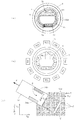
図1(a)は、本発明の第1の実施形態に係る競馬ゲーム装置1の外観構成を示す斜視説明図である。
FIG. 1A is an explanatory perspective view showing an external configuration of a horse
図示されるように、この競馬ゲーム装置1は、後述の主制御基板21などが収容される筐体中央の略円柱状の装置本体部2と、装置本体部2の周囲に配置され、通信ケーブルなどを介して上記主制御基板21と電気的に接続される複数のサテライト(操作盤)80とを主体に構成されている。
As shown in the figure, this horse
なお、図1(a)では、簡略のために手前の3台のサテライト90a〜90cのみが示されているが、本実施形態の競馬ゲーム装置1においては、12台のサテライト90a〜90lが装置本体部2の周囲に配置されている。
In FIG. 1 (a), only the three
図1(b)は、装置本体部2の構成を示す斜視説明図である。
FIG. 1B is a perspective explanatory view showing the configuration of the apparatus
図示されるように、装置本体部2は、円筒状の外側筐体3と、当該外側筐体3の内側に収容され、上下に離間して配置された上面板4及び下面板7からなる2階建て構造とを備えている。
As shown in the drawing, the apparatus
上面板4は、概略円形の形状を有する板状の部材であり、その上側表面である第1走行面4sはサテライト90に位置する遊戯客などから視認することが可能である。第1走行面4sには、競馬ゲーム(レース)において複数の走行体50が着順を競って走行する走路であるトラック5が形成されている他、当該トラック5上の走行体50を撮影する複数のフィールドカメラ22a及びゴールカメラ22b、各カメラ22a、22bにより撮影された画像やレースの案内などの情報を表示するモニタ装置23などが配置されている。また、本実施形態では、競馬場の外観をリアルに再現するために、トラック5及びその周辺には、緑色の粉末や繊維等を加工した人工芝材などが敷き詰められている。
The
なお、図には示されていないが、本実施形態では、各レースにおいてトラック5上を走行する走行体50の台数変更を可能にするために、装置本体部2は、上面板4の外周部等の適宜の箇所に走行体50を収容する収容部を備えることが可能である。
Although not shown in the figure, in the present embodiment, in order to enable the number of traveling
更に、装置本体部2は、現実の競馬と同様のスタートシーンを再現するために、各レースの開始時にスタート地点に配置され、レース中には上面板4の外周部等の適宜の箇所に退避収容される出走ゲートを更に備えることが可能である。この場合の出走ゲートは、例えば、特開平10−216355号公報に開示される出走ゲートと同様の構成とすることができる。
Further, the apparatus
図2(a)は、装置本体部2を俯瞰視で示す説明図である。
FIG. 2A is an explanatory diagram showing the apparatus
図示されるように、上記トラック5は、8の字状に形成されている。従って、本実施形態の競馬ゲーム装置1では、レースの種類に応じてスタート地点である5a又は5bからゴール5cに至る符号5S、5M、5Lで示す複数種類の走行コースを変更することにより、短距離、中距離、長距離など複数種類の走行コースでのレースを行うことが可能である。
As shown in the figure, the
図2(b)は、上面板4から所定距離下方に離間した位置において上面板4と平行に敷設された下面板7を装置本体部2の周辺に配置されたサテライト90a〜90lとともに平面視で示す説明図である。
FIG. 2B is a plan view of the
図示されるように、下面板7は、上面板4と同様円形形状を有する板状の部材であり、その上側表面である第2走行面7sのトラック5に対応する領域は、レースにおいて複数の自走体30が走行する走路8とされている。
As shown in the drawing, the
また、走路8は、装置周辺の12台のサテライト90a〜90lのそれぞれに対応付けられた12のサテライト対応領域8a〜8lに区画されている。
The
各サテライト対応領域8a〜8lの大小関係や配置、或いは、走路8の全面積を余すことなくいずれかのサテライト対応領域8a〜8lに区画するか否かなどは任意ではあるが、本実施形態では、全てのサテライト対応領域8a〜8lが概略同一の面積を有し、かつ、各サテライト対応領域8a〜8lが対応するサテライト90a〜90lに最も近い位置となるように配置されている。
The size and arrangement of the satellite corresponding regions 8a to 8l, or whether or not the satellite corresponding regions 8a to 8l are partitioned without leaving the entire area of the
なお、各サテライト対応領域8a〜8lの位置乃至境界は、主制御基板21又は自走体制御基板101において認識されるデータとして定義されるものであり、図示のように視認できる態様で境界線が引かれている訳ではない。また、後述のように、各自走体30の走路8上での位置は、それぞれ対応する走行体50のトラック5上の位置に一致するため、走路8がサテライト対応領域8a〜8lに区画されていることは、トラック5が同等の領域に区画されているのと同義である。
The positions or boundaries of the satellite corresponding regions 8a to 8l are defined as data recognized by the main control board 21 or the self-propelled
図2(c)は、第2走行面7sにおける2次元コードCの配列の様子を下面板7に配置された自走体30とともに示す説明図である。
FIG. 2C is an explanatory view showing the arrangement of the two-dimensional code C on the second traveling
第2走行面7sの全体又は少なくとも走路8の表面は、第2走行面7sに固定された直交座標であるグローバル座標上における位置座標を記録した多数の2次元コードCが配置された情報配置面とされている。なお、本実施形態では、2次元コードCとしてQRコード(JIS−X−0510)が使用されている。
The entire second traveling
ここで、QRコードは、図2(c)に示すように、グローバル座標のXg軸及びYg軸方向にそれぞれ一定間隔をもって行列状に配列されるとともに、各QRコードは、QRコード上の直交座標であるQR座標上のXqr軸及びYqr軸方向が、グローバル座標上のXg軸及びYg軸方向と一致する角度で配置されている。 Here, as shown in FIG. 2 (c), the QR codes are arranged in a matrix form with a constant interval in the Xg axis direction and the Yg axis direction of the global coordinates, and each QR code is an orthogonal coordinate on the QR code. The Xqr axis and Yqr axis directions on the QR coordinates are arranged at an angle that matches the Xg axis and Yg axis directions on the global coordinates.
QRコードは、自走体30に搭載されるカメラ装置36の撮影角及びカメラ装置36から第2走行面7sまでの距離を考慮して、走路8上のどの位置に自走体30が位置する場合でも、カメラ装置36の画角(撮影視野)V内に常に1以上のQRコードの全体が含まれるサイズ及び間隔で配置されており、後述の自走体制御基板101は、カメラ装置36による撮影画像中のQRコードに記録された位置情報と、カメラ装置36により撮影された画像に固定された座標系であるカメラ座標(Xc、Yc)上でのそのQRコードの位置及び角度とに基づいて、グローバル座標上における自走体30の基準点(例えば、中央輪34a、34bの車軸中央位置)Rの位置座標及び角度(進行方向)Fを導出する。なお、撮影画像中における一のQRコードからの位置情報の取得に失敗した場合における他のQRコードからの位置情報の取得を可能にするべく、QRコードは、カメラ装置36の画角V内に常に2以上のQRコードの全体が含まれるサイズ及び間隔で配置されていることが好ましい。
The QR code considers the shooting angle of the
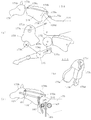
図3は、第2走行面7sに配置された自走体30と、第1走行面4sに配置された走行体50を側面視で示す説明図である。
FIG. 3 is an explanatory diagram showing the self-propelled
図示されるように、自走体30は、台車31及び支持台40から構成されている。
As illustrated, the self-propelled
台車31には、前後輪32、33と、左右の中央輪34a、34bと、当該中央輪34a、34bをそれぞれ駆動する走行モータ35a、35bとが搭載されており、走行制御基板106に制御された走行モータ35a、35bが左右の中央輪をそれぞれ独立に駆動することにより、進行方向を変更自在に自走体30を第2走行面7s上で自力走行(自走)させることが可能である。
The
台車31には、更に、第2走行面7sを上方から垂直に撮影するCCDカメラなどのカメラ装置36と、カメラ装置36の両側部に取り付けられ、カメラ装置36の画角Vを照明する白色LED37と、無線LANによる装置本体部2との通信を行うためのアンテナ38などの機構部品を備えている。
The
支持台40は、スプリング41による上方への付勢力を受けた状態で台車31の上方に取り付けられている。
The
支持台40の上面には、前後輪42、43と、左右の中央輪44a、44bとが取り付けられ、これら車輪42〜44は、スプリング41の付勢力により上面板4の下面に当接する。従って、自走体30は、下部の車輪42〜44と、上部の車輪42〜44に挟まれて、上面板4と下面板7の間の走行空間を直立姿勢を維持しながら安定に走行することができる。
Front and
支持台40の上部には、駆動磁石45a〜45c及び模型制御モータ46a〜46cが更に取り付けられている
Drive
駆動磁石45a〜45cは、相互に所定の間隔をもって、また、上面板4に対しても若干の距離を離間させるように取り付けられており、模型制御モータ46a〜46cの駆動により、鉛直方向の軸を中心に回転動作を行うようになっている。駆動磁石45a〜45cは、後述の従動磁石55a〜55cと磁気的に結合し、自走体30の走行により上面板4上の走行体50を牽引するとともに、従動磁石55a〜55cを回転させることによって走行体50上の模型体57に取り付けられた可動部材(馬模型58の前後脚部や騎手模型59の手足部など)を揺動動作させ、或いは、模型体57を馬体回転軸である円柱状突起us3の周りで回転動作させる。なお、本実施形態の模型制御モータ46a及び46cには、ステッピングモータが採用されており、騎手模型59の手足部の揺動動作や模型体57の回転動作を数値制御することが可能である。
The
支持台40には、更に、給電板6から電力を受電して、後述の自走体制御基板101、撮影制御基板102、LED制御基板103、画像処理基板104、画像メモリ105、走行制御基板106、模型制御基板107、無線LAN装置108などへの給電を行うための集電装置47が接続されている。
The
支持台40上部における駆動磁石45aの前方位置には、更に駆動磁石45aから所定の距離を離間させてホール素子48が取り付けられている。ホール素子48は自走体制御基板101に電気的に接続されており、自走体制御基板101は、台車51に取り付けられた磁石55dとホール素子48の位置関係により変化するホール電圧によって、走行体50が自走体30に対して正しい位置及び方向にセットされているか否かを検知することが可能である。
A
走行体50は、台車51と、台車51に立設された支持柱56及び馬体駆動軸64により支持される模型体57とから構成されている。
The traveling
台車51は、前後輪52、53と、台車51の両側部に軸支された中央輪54a、54bとにより第1走行面4s上を走行可能とされており、台車51の下面には、第1走行面4sから若干の間隔を離間させて、かつ、自走体30の駆動磁石45a〜45cと対応する配置をもって3つの従動磁石55a〜55cが取り付けられている。
The
従動磁石55a〜55cは、自走体30の駆動磁石45a〜45cと磁気的に結合し、第2走行面7s上を走行する自走体30に追従して(自走体30と所定の位置関係を保った状態で)走行体50が第1走行面4s上を走行することを可能にする。
The driven
従動磁石55a〜55cは、概略鉛直方向の軸を中心に回転可能とされ、自走体30の駆動磁石45a〜45cの回転に同期して回転する。
The driven
なお、台車51の下面における従動磁石55aの更に前方位置には、第1走行面4sから若干の間隔を離間させて、上述の磁石55dが取り付けられている。
Note that the
模型体57は、現実の競走馬を象った馬模型58と、現実の騎手を象った騎手模型59とから構成され、上記従動磁石55a、55bの回転は、支持柱56に収容された騎手駆動軸62、馬脚駆動軸63を介して模型体57に伝達され、馬模型58及び騎手模型59に取り付けられた複数の可動部材を揺動等させる。また、従動磁石55cの回転は、馬体駆動軸64の上下動に変換され、これにより模型体57は馬体回転軸(円柱状突起us3)の周りで上下に回転し、馬模型58が後脚立ち姿勢や前脚立ち姿勢を取ることを可能にする。
The
図4(a)は、模型体57を取り外した状態で台車51の外観を示す斜視説明図であり、図4(b)は、図4(a)の台車51のカバー部材61を取り除いてその内部構造を示す斜視説明図である。
4 (a) is a perspective explanatory view showing the appearance of the
本実施形態の台車51は、板状のベース部材60とその上部を覆うカバー部材61を備えており、ベース部材60の下面には、3つの従動磁石55a〜55cが鉛直方向を回転軸として回転自在に取り付けられている。
The
カバー部材61の上方には、騎手駆動軸62及び馬脚駆動軸63をその内部空間に収容した支持柱56及び馬体駆動軸64がそれぞれ鉛直方向に向けて立設されており、支持柱56の上端にはウォームギアボックス65が、馬体駆動軸64の上端には牽引部材66がそれぞれ取り付けられている。
Above the
また、カバー部材61に覆われた内部空間には、上記従動磁石55a〜55cの回転力を、それぞれ騎手駆動軸62、馬脚駆動軸63及び馬体駆動軸64に伝達する複数の歯車などで構成される動力伝達機構が収容されている。
The internal space covered with the
即ち、ベース部材60の上面前方位置には、それぞれ鉛直方向の軸の周りに回転自在の3つの平歯車dg1〜dg3が相互に歯合し合う態様で取り付けられており、平歯車dg1は、従動磁石55aと後述のトルククラッチ機構68aを介して連結され、平歯車dg3は、騎手駆動軸62と一体となって回転する平歯車dg4と歯合している。従って、従動磁石55aが回転すると、その回転が平歯車dg1〜dg4により伝達されて騎手駆動軸62が回転する。
That is, three spur gears dg1 to dg3 that are rotatable around a vertical axis are respectively attached to the front surface of the upper surface of the
また、ベース部材60の下面概略中央に取り付けられた従動磁石55bは馬脚駆動軸63にトルククラッチ機構68bを介して直接連結されており、従動磁石55bが回転すると、騎手駆動軸63はこれと一体となって回転する。
Further, the driven
図5(a)は、支持柱56の内部に収容される上記騎手駆動軸62及び馬脚駆動軸63と、その上端のウォームギアボックス65との連結の態様を示す分解斜視図である。
FIG. 5A is an exploded perspective view showing a state of connection between the
図示のように、支持柱56は中空円筒状部材であり、支持柱56の筒内には、中空円筒状の騎手駆動軸62がその上端及び下端を支持柱56から突出させる態様で挿通されており、更に、当該騎手駆動軸62の筒内には、円柱状の馬脚駆動軸63がその上端及び下端を騎手駆動軸62から突出させる態様で挿通されている。騎手駆動軸62及び馬脚駆動軸63は、その鉛直方向の中心軸の周りに相互に自由に回転することが可能である。
As shown in the drawing, the
そして、支持柱56の上端が、ウォームギアボックス65の下部に設けられた孔65aに挿通固定され、支持柱56から上方に突出した騎手駆動軸62及び馬脚駆動軸63の上端は、孔65aを貫通してウォームギアボックス65の内部空間まで延在しており、騎手駆動軸62の先端には騎手駆動軸62と一体に回転するウォーム62aが取り付けられ、馬脚駆動軸63の先端には馬脚駆動軸63と一体に回転するウォーム63aが取り付けられている。
The upper end of the
ウォームギアボックス65の側壁に設けられた2つの軸孔65b、65cには、それぞれ水平方向のシャフトus1、us2が挿通固定されており、下方側のシャフトus1には、ウォーム62aに切られた螺旋状の螺子溝と歯合する螺子歯車(ウォームホイール)ug1及びこの螺子歯車ug1と一体に形成された平歯車ug2から成る歯車ユニットug3と、平歯車ug2と同径の平歯車ug4とが軸挿されている。歯車ユニットug3と平歯車ug4は、シャフトus1の周りで相互に独立に回転することが可能である。
Horizontal shafts us1 and us2 are inserted and fixed in two
上方側のシャフトus2には、ウォーム63aと歯合する螺子歯車ug5及び該螺子歯車ug5と一体に形成され、上記平歯車ug4と歯合する平歯車ug6から成る歯車ユニットug7が軸挿されている。 A gear unit ug7 that is formed integrally with the screw gear ug5 and the screw gear ug5 and meshes with the spur gear ug4 is inserted into the shaft us2 on the upper side. .
このように、従動磁石55aは、騎手駆動軸62及びこれに固定されたウォーム62aを介して歯車ユニットug3に連結されており、従動磁石55aを回転させることにより平歯車ug2を回転させることが可能である。同様に、従動磁石55bは、馬脚駆動軸63及びこれに固定されたウォーム63a、歯車ユニットug7を介して平歯車ug4に連結されており、従動磁石55bを回転させることにより、平歯車ug4を回転させることが可能である。
Thus, the driven
また、ウォームギアボックス65の両側壁には、外方に向けてシャフトus1、us2と同心に円柱状突起us3、us4が突設されている。この円柱状突起us3は、模型体57の回転運動の中心軸である馬体回転軸として機能し、円柱状突起us4は、その回転を案内するガイドとして機能する。
In addition, columnar protrusions us3 and us4 project from the both side walls of the
図4に戻って、ベース部材60の上面後方位置には、鉛直方向の軸の周りに回転自在の3つの平歯車dg5〜dg7が相互に歯合し合う態様で取り付けられており、平歯車dg5は、従動磁石55cとトルククラッチ機構68cを介して連結されている。
Returning to FIG. 4, three spur gears dg <b> 5 to dg <b> 7 that are rotatable around a vertical axis are attached to the rear surface of the upper surface of the
図5(b)は、平歯車dg5〜dg7、馬体駆動軸64及び牽引部材66の連結の態様を示す分解斜視図である。
FIG. 5B is an exploded perspective view showing a connection mode of the spur gears dg5 to dg7, the
図示のように、馬体駆動軸64は、棒状のシャフト64aと、バネ部材64bと、ピン挿通孔64cが形成された円筒部材64dと、雄螺子部材64eからなる棒状の部材であり、その円筒部材64dよりも下方部分は、ベース部材60に螺子留めなどにより固定される台座67に形成された孔67aに挿通され、雄螺子部材64eの下端は当該孔67aを貫通して、平歯車dg7の中心孔に切られた雌螺子に累合するようになっている。
As shown in the figure, the
また、台座67の側面には、円筒部材64dのピン挿通孔64cに挿通されるガイドピン67cを上下方向に案内する1対の長穴67bが形成されている。従って、馬体駆動軸64は、上記ガイドピン67c及び長穴67bにより、その長手方向軸(鉛直方向の軸)周りの回転が禁止され、上下方向への移動のみが可能となっている。
Further, a pair of
なお、バネ部材64bは、上記馬体駆動軸64が上下方向に移動する際の馬体駆動軸64のしなりを吸収するための弾性手段として機能するものである。
The
図5(c)は、従動磁石55a〜55cをそれぞれ平歯車dg1、馬脚駆動軸63、平歯車dg5に連結させるトルククラッチ機構68a〜68cの例示的な構成を示す斜視説明図である。
FIG. 5C is a perspective explanatory view showing an exemplary configuration of torque clutch mechanisms 68a to 68c for connecting the driven
図示のように、各トルククラッチ機構部68a〜68cは、例えば、金属製の2つの円盤状板バネ部材681と、2つの球状のボール部材682と、円盤状の固定部材683と、円盤状の磁石取付板部材684などから構成される。
As shown, each torque clutch mechanism 68a~68c, for example, two disk-like plate spring member 681 made of metal, and the two
ここで、固定部材683は、平歯車dg1、馬脚駆動軸63又は平歯車dg5と一体となって回転する部材であり、磁石取付板部材684の下面にはボール部材682を受ける凹陥部が複数個(例えば、8個など)形成され、固定部材683には、ボール部材682を転動可能に収容する2つの貫通孔が形成されるとともに、その下面には板バネ部材681に形成された2つの孔に嵌合する2つの突起部が形成されている。
Here, the fixing member 683 is a spur gear dg1, a member which rotates integrally with the true colors drive
従って、各トルククラッチ機構68a〜68cでは、磁石取付板部材684に固定された従動磁石55a〜55cによる回転力が一定のトルクに達するまでは、磁石取付板部材684と固定部材683とが一体となって回転し、その回転力が平歯車dg1、馬脚駆動軸63又は平歯車dg5に伝達され、一方、従動磁石55a〜55cの回転力が一定のトルクを超えた場合には、磁石取付板部材684が固定部材683に対して空回りし、平歯車dg1、馬脚駆動軸63又は平歯車dg5への上記回転力の伝達が遮断される。
Thus, in each of the torque clutch mechanism 68a to 68c, to the rotational force by the driven
従動磁石55a〜55cと平歯車dg1、馬脚駆動軸63及び平歯車dg5は、上述のようなトルククラッチ機構68a〜68cを介して連結されているために、何らかの原因で許容範囲を超える回転力が発生した場合における台車51又は模型体57を構成する歯車等の部品が破損するなどの不都合を解消することが可能である。
Since the driven
図6は、頭部、首部、胴体部などの各外装材を取り除いた馬模型58を示す斜視説明図であり、図7は、馬模型58の前脚部及び後脚部の部品構成を示す分解斜視説明図であり、図8は、馬フレーム70の内部に収容される可動部材駆動機構を示す分解斜視図である。
FIG. 6 is an explanatory perspective view showing the
図示のように、本実施形態の馬模型58は、一対の馬フレーム70、70と、この馬フレーム70、70に摺動板部材73、連結部材74、回転盤部材75等を介して取り付けられた前脚部76、後脚部77、及び、首骨部材78、尻尾部材79などで構成されており、これらの周囲に外装材を取り付けることで図3に示す競走馬の形状が与えられている。
As shown in the figure, the
馬フレーム70の長手方向概略中央には、両馬フレーム70の間の空間(以下、馬体空間という)に内挿されたウォームギアボックス65の円柱状突起us3を軸挿する軸孔70aと、円柱状突起us4を案内する円弧状のガイド孔70bが穿孔されており、馬フレーム70は、ガイド孔70bにより円柱状突起us4の移動が許容される範囲で回転可能に円柱状突起us3に枢着されている(円柱状突起us3に対して回転可能に取り付けられている)。
At the approximate center in the longitudinal direction of the
また、上記馬体空間には、ウォームギアボックス65の平歯車ug2、ug4と係合して騎手模型59や馬模型58の前脚部を揺動させる図8に示す複数の歯車などで構成される動力伝達機構が収容される。
Further, in the horse space, the power constituted by a plurality of gears shown in FIG. 8 that engage with the spur gears ug2 and ug4 of the
即ち、上記馬体空間における右側の馬フレーム70寄りの位置には、相互に歯合し合う3つの平歯車mg1〜mg3が取り付けられており、平歯車mg3には、馬フレーム70の前方に取り付けられたベアリング71aに水平に軸支されるシャフトms2が固定されている。
That is, three spur gears mg1 to mg3 that mesh with each other are attached to a position near the
また、左側の馬フレーム70寄りの位置には、相互に歯合し合う3つの平歯車mg4〜mg6が取り付けられている。平歯車mg6の偏心位置には、ワイヤーロッドwの下端を係止する係止孔mg6aが穿孔されており、その右側側面には、左側の馬フレーム70内壁に突設された不図示の突設ピンを挿通する概略C形状の案内溝mg6bが刻設されており、平歯車mg6は、案内溝mg6bが突設ピンによる規制を受けるために、係止孔mg6aが最下位置から最上位置に移動するまでの180度の角度範囲でのみ回転可能とされている。
Further, three spur gears mg4 to mg6 that mesh with each other are attached to a position near the
ここで、平歯車mg1及びmg4は、両馬フレーム70、70の内側に穿孔された軸孔70cに水平に差し渡されたシャフトms1に軸支される同径の歯車であり、平歯車mg1はウォームギアボックス65の平歯車ug4に歯合し、平歯車mg4はウォームギアボックス65の平歯車ug2に歯合する。
Here, the spur gears mg1 and mg4 are gears of the same diameter supported by the shaft ms1 horizontally inserted in the
従って、従動磁石55bの回転は、馬脚駆動軸63、ウォーム63a、歯車ユニットug7、ug4、平歯車mg1〜mg3を介して伝達されてシャフトms2を回転させて前後脚部76、77を揺動動作させ、従動磁石55aの回転は、騎手駆動軸62、ウォーム62a、歯車ユニットug3、mg4〜mg6を介して伝達されてワイヤーロッドwの上下動に変換されて、騎手模型59の手足部82〜85を揺動動作させる。
Accordingly, the rotation of the driven
このように、可動部材である馬模型58の前後脚部76、77や騎手模型59の手足部82〜85に駆動力を伝達するための駆動力が、馬体回転軸である円筒状突起us3と同心のシャフトus1を軸芯とする歯車ユニットug3又は平歯車ug4を介して伝達されるために、これらの可動部材への動力の伝達に影響を与えることなく模型体57を馬体回転軸の回りで回転させることが可能となっている。
Thus, the cylindrical projection us3 that is the driving force for transmitting the driving force to the front and
なお、上記シャフトms2には、一部が切り欠かれて断面視がC字状となったリング部材mrが嵌着され、このリング部材mrは、係合部材mkに形成された円形開口に内挿されるようになっている。 The shaft ms2 is fitted with a ring member mr that is partially cut out and has a C-shaped cross-sectional view. The ring member mr is fitted in a circular opening formed in the engagement member mk. It is supposed to be inserted.
馬フレーム70の長手方向前方位置には、摺動板部材73を取り付けるための構造として、ベアリング71aを内挿した円環状突起71b、摺動板部材73の厚みだけ凹陥した平滑な概略扇状の摺動面71c、スプリング71dを収容するスプリング溝71e、円弧状のガイド孔71fなどが形成されている。
At the front position in the longitudinal direction of the
なお、摺動面71cの裏面側上方位置には、首骨部材78の後方に穿孔された軸孔78aを回転自在に軸支するシャフト71gが突設されている。
A
摺動板部材73は、上部に開口73aが形成され、下部が扇形の形状を成す部材であり、扇状の部分の前方には、スプリング溝71eのスプリング71dに当接する受座73bと、前脚部76を揺動自在に枢着する軸孔73cとが形成されており、その後方には、ガイド孔71fに案内されるガイドピン73dが突設されている。
The sliding
摺動板部材73は、開口73aを円環状突起71bに挿通させて摺動面71cに収容され、受座73bに当接するスプリング71dによる後方への付勢力を受けた状態で、カイド孔71f内でのガイドピン73dの移動が許容される範囲で円環状突起71bの周りに回転可能とされている。
The sliding
摺動板部材73の外側には、回転盤部材75及び回転盤部材75の円環状突起75bに枢着された連結部材74を介して前脚部76が取り付けられている。
A
回転盤部材75は、中央に形成された螺子孔75aにおいて螺子止めなどによってシャフトms2に固定されてシャフトms2と一体に回転する部材であり、その内側表面及び外側表面の偏心位置には、それぞれ円環状突起75b及びガイドピン75cが突設されている。
The
前脚部76は競走馬の前脚の外観を模した外形を有する棒状の部材であり、その上部には、回転盤部材75のガイドピン75cを案内する直線状の長穴76aが形成されるとともに、揺動軸76bを中心に回転自在とされた回転部材76cが取り付けられ、その概略中央付近の内側表面には、摺動板部材73の軸孔73cに軸支される揺動軸76dが突設され、更に、その下端付近の外側表面には、下肢部分76fを回転自在に軸支する軸ピン76eが突設されている。
The
下肢部分76fは、上記軸ピン76eによって軸支されるとともに、その下方位置には、スプリング76gの付勢力を受けて上端を上記回転部材76cの先端に取り付けられた連結部材76hの下端が取り付けられている。
The
また、馬フレーム70の長手方向後方位置には、後脚部77の厚みだけ凹陥した概略円形の摺動面72aが形成されている。また、摺動面72aの中央には、円柱状の突起軸72bが、その下方には、シャフト72cが突設されており、突起軸72bの後方には、馬体空間に収容された牽引部材66の牽引シャフト66aを枢着する駆動孔72dが穿孔され、更に、摺動面72aの上部後方位置には、尻尾部材79の揺動軸79aを枢着する軸孔72eが穿孔されている。その他、左側の馬フレーム70の摺動面72aには、尻尾部材79のシャフト79bを案内する直線状のガイド孔72fが穿孔され、右側の馬フレーム70の摺動面72aには、右側の後脚部77に形成されたシャフト77iを挿通する円弧状の挿通孔72gが穿孔されている。
Further, a substantially circular sliding
後脚部77は競走馬の後脚の外観を模した外形を有する部材であり、その前方には、摺動面72aに収容される円盤部77aを有しており、当該円盤部77aは、その中心位置に突起軸72bを回転自在に枢着する枢着孔77bを有するとともに、その偏心位置に円柱突起77cが突設されている。更に、枢着孔77bの周囲には、馬フレーム70のシャフト72cを案内する円弧状のガイド孔77d及び尻尾部材79のシャフト79bを案内する直線状のガイド孔77eが穿孔されている。
The
後脚部77は、突起軸72bに枢着孔77bを枢着させて摺動面72a内において円盤部77aを自在に回転させることが可能な態様で馬フレーム70に取り付けられ、更に、その外側に連結部材74が取り付けられる。
The
連結部材74は、回転盤部材75の回転を後脚部77に伝達するための棒状の部材であり、その前方の開口74aには回転盤部材75の円環状突起75bを枢着し、後方の開口74bには円盤部77aの円柱突起77cを枢着するようになっている。
The connecting
また、後脚部77の下端付近の外側表面には、下肢部分77gを回転自在に軸支する軸ピン77fが突設されている。
In addition, a shaft pin 77f that rotatably supports the
下肢部分77gは、上記軸ピン77fによって軸支されるとともに、その下方位置には、シャフト72cに上端を軸支された連結部材77hが取り付けられている。
The
図9(a)は、騎手模型59の外観を示す斜視説明図であり、図9(b)は、騎手模型59の部品構成を示す分解斜視図である。
FIG. 9A is a perspective explanatory view showing the appearance of the
図示されるように、本実施形態の騎手模型59は、現実の騎手を象った模型であり、左胴体部80と、右胴体部81と、左腕部82と、右腕部83と、左足部84と、右足部85と、足下付き鞍部86と、駆動部材87とから構成されている。
As shown in the figure, the
そして、本実施形態の騎手模型59は、左胴体部80のシャフト80a及び80bに、左腕部82の枢着穴82a及び左足部84の枢着穴84aがそれぞれ枢着される態様で、左胴体部80に左腕部82及び左足部84が装着されており、同様に、右胴体部81のシャフト81a及び81bに、右腕部83の枢着穴83a及び右足部85の枢着穴85aがそれぞれ枢着される態様で、右胴体部81に右腕部83及び右足部85が装着される。
And the
左胴体部80の内側には、駆動部材87を上下方向に移動可能に収容する空間が形成されおり、上記左腕部82及び左足部84が装着された左胴体部80に、左胴体部80の円弧状のガイド溝80cに挿通された左腕部82のシャフト82bを駆動部材87の上端側に設けられた長穴87aに挿通し、左足部84のシャフト84bを他端側の枢着孔87bに挿通する態様で駆動部材87が左胴体部80の内側の空間に収容される。駆動部材87の中央部に穿孔された連結孔87cには、ワイヤーロッドwの上端が係合される。
A space that accommodates the
上記のようにして、左腕部82、左足部84を取り付けられ、駆動部材87を収容した左胴体部80と、右腕部83及び右足部85を取り付けられた右胴体部81とが螺子留めなどにより接合される。
As described above, the
また、左足部84及び右足部85の膝部分に形成されたシャフト84c、85bが、足下付き鞍部86の枢着孔86a、86bにそれぞれ枢着される。なお、左腕部82には、鞭部材88が嵌合されて固定されている。
Further,
次ぎに、従動磁石55a、55bが駆動磁石45a、45bに駆動されて回転した場合における馬模型58の可動部材である前脚部76及び後脚部77、騎手模型59の可動部材である胴体部80、81及び手足部82〜84の動作態様、並びに、従動磁石55cが駆動磁石45cにより駆動されて回転した場合における模型体57の馬体回転軸である円柱状突起us3の周りでの回転運動の態様を図10〜図12を参照しつつ説明する。
Next, when the driven
図10(a)は、従動磁石55bの回転を回転盤部材75に伝達する馬体駆動機構を抽出して示す説明図である。
FIG. 10A is an explanatory view showing an extracted horse drive mechanism that transmits the rotation of the driven
図示されるように、従動磁石55bの回転は、馬脚駆動軸63、ウォーム63a、歯車ユニットug7、平歯車ug4、平歯車mg1〜mg3及びシャフトms2を介して伝達されて回転盤部材75を回転させる。
As shown in the figure, the rotation of the driven
図10(b)は、回転盤部材75が1回転する間における前脚部76及び後脚部77の揺動の態様を側面視で示す説明図である。
FIG. 10B is an explanatory view showing a swinging mode of the
図10(A)の状態を初期姿勢と呼ぶものとすると、初期姿勢(A)においては、回転盤部材75はガイドピン75cが軸芯75aの直上となる回転位置にあり、前脚部76は概略鉛直下方に垂下した状態にある。
If the state of FIG. 10A is called an initial posture, in the initial posture (A), the
この初期姿勢(A)から回転盤部材75が回転すると、その偏心位置にあるガイドピン75cが前脚部76の長穴76a内を下方に移動し、これにより、前脚部76は揺動軸76dの周りで前方に向けて回転駆動される。このとき、揺動軸76dは、ガイドピン75cから前方に向かう付勢力を受けることになり、この付勢力により、揺動軸76dを枢着した摺動板部材73がスプリング71dの付勢力に抗して円環状突起71bの周りで前方方向に回転し、これにより、揺動軸76dの馬模型58上での位置が前方に移動する。
When the
この間、回転盤部材75の回転は、円環状突起75bに枢着された連結部材74により後脚部77の円柱突起77cにも伝達され、後脚部77は突起軸72bの周りに後方に向けて回転駆動される。
During this time, the rotation of the
ガイドピン75cが長穴76aの中間における特定位置に達したところで、馬模型58は、前脚部76が最も前方に回転し、揺動軸76dが最も前方に移動し、かつ、後脚部77が最も後方に回転した状態である開脚姿勢(B)となる。
When the
なお、馬模型58が初期姿勢(A)から開脚姿勢(B)に至る過程では、前脚部76の下肢部分76f及び後脚部の下肢部分77gは、スプリングの付勢力によってそれぞれ最も前方及び後方に回転した状態に維持される。
In the process of the
回転盤部材75が更に回転すると、ガイドピン75cは長穴76aの最下点を通過して上昇していくことになり、これにより、前脚部76は揺動軸76dの周りで後方に向けて回転駆動される。このとき、揺動軸76dへのガイドピン75cからの上記付勢力は徐々に小さくなっていくために、揺動軸76dを枢着した摺動板部材73はスプリング71dの付勢力によって後方に回転し、揺動軸76dの馬模型58上での位置は、前脚部76の後方への回転に同期して後方に移動する。また同時に、後脚部77は、ガイドピン75cに枢着された連結部材74により駆動されて前方に向けて回転する。そして、ガイドピン75cが長穴76aの中間における特定位置に達したところで、馬模型58は、前脚部76を鉛直下方に垂下させた初期姿勢(A)と同一の初期姿勢(C)を取ることになる。
When the
なお、開脚姿勢(B)から初期姿勢(C)に至る過程では、前脚部76の下肢部分76f及び後脚部77の下肢部分77gはそれぞれ最も前方及び後方に回転した状態に維持される。
Note that, in the process from the open leg posture (B) to the initial posture (C), the
そして、初期姿勢(C)から更に回転盤部材75が回転すると、ガイドピン75cが長穴76a内を更に上昇し、前脚部76は揺動軸76dの周りで更に後方に向けて回転駆動され、後脚部77はガイドピン75cに枢着された連結部材74により駆動されて更に前方に向けて回転駆動される。
When the
このとき、長穴76aを上昇するガイドピン75cにより前脚部76の上端に取り付けられた回転部材76cが押し上げられて上方に回転し、これにより、回転部材76cに取り付けられた連結部材76hが上方に移動して下肢部分76fを牽引し、下肢部分76fが軸ピン76eの周りに後方に向けて回転することになる。同様に、後脚部77の前方への回転が一定以上に達すると、円柱突起77cに取り付けられた連結部材77hによる牽引によって下肢部分77gは前方に回転する。
At this time, the rotating
ガイドピン75cが長穴76aの最上位置に到達したところで、馬模型58は、前脚部76が最も後方に回転し、かつ、後脚部77が最も前方に回転した状態である閉脚姿勢(D)となる。
When the
回転盤部材75が更に回転すると、やがては馬模型58は初期姿勢(A)に復帰し、その後は(A)〜(D)のサイクルが反復する。
When the
上記のように、本実施形態における馬模型58では、馬模型58上における揺動軸76dの位置が前後に移動し、これに同期してその揺動軸76dの周りで可動部材76が揺動するように構成されているため、馬模型58上における揺動軸76dの位置を固定した状態で可動部材76を揺動させる場合と比較して、よりダイナミックな態様で可動部材76を揺動させることが可能であり、現実の動物が高速で走行しているときのような躍動感のある走行態様を模擬することが可能になる。
As described above, in the
なお、本実施形態の馬模型58では、従動磁石55bの回転による上記前脚部76及び後脚部77の揺動に同期して、更に首骨部材78が前後に移動し、尻尾部材79が上下に揺動(振動)するようになっている。
In the
即ち、従動磁石55bの回転によりシャフトms2が回転すると、これに嵌着されたリング部材mrが係合部材mkの開口内で回転し、係合部材mkはリング部材mrの切欠部分が下に来たときには上方に持ち上げられ、これが上に来たときには首骨部材78またはその外装材の重量により下降する態様で上下に揺動する。そして、この揺動運動が、係合部材mkの前端のピンに係合するピン孔78bに伝達されることにより、首骨部材78がシャフト71gに枢着された軸孔78aの周りで揺動することになる。
That is, when the shaft ms2 is rotated by the rotation of the driven
また、尻尾部材79のシャフト79bは、摺動面72aに穿孔された直線状のガイド孔72fと、後脚部77の円盤部77aに穿孔された直線状のガイド孔77eが交わる交差空間に支持されることになるが、この交差空間は、尻尾部材79の揺動によってガイド孔72f上を前後に移動することになるため、シャフト79bは交差空間の移動に従って前後に駆動され、これにより尻尾部材79は、軸孔72eに枢着された揺動軸79aの周りで揺動することになる。
Further, the
図11(a)は、従動磁石55aの回転を駆動部材87に伝達する騎手駆動機構を抽出して示す説明図である。
FIG. 11A is an explanatory diagram showing an extracted jockey drive mechanism that transmits the rotation of the driven
図示されるように、従動磁石55aの回転は、平歯車dg1〜dg4、騎手駆動軸62、ウォーム62a、歯車ユニットug3の平歯車ug2、平歯車mg4〜mg6に伝達され、平歯車mg6を回転させる。このとき、平歯車mg6の回転は、案内溝mg6bに挿通された突設ピンの規制を受けて、係止孔mg6aが最下位置から最上位置に移動するまでの半回転の範囲においてのみ往復回転が可能である。従って、平歯車mg6の回転により、平歯車mg6の係止孔mg6aに係止されたワイヤーロッドw及びこれに連結された駆動部材87を最下位置から最上位置の範囲で駆動する。
As shown in the figure, the rotation of the driven
図11(b)は、従動磁石55aの回転により、係止孔mg6a(駆動部材87)が最下位置から最上位置に移動する間における騎手模型59の動作態様を側面視で示す説明図である。なお、図11(b)では、右胴体部81、右腕部83及び右足部85を取り除いた騎手模型59の左半分の内部構造が示されている。
FIG. 11B is an explanatory view showing the operation mode of the
駆動部材87が最下位置にある場合、騎手模型59は、図11(b)の上部に示す第1姿勢(A)を取る。即ち、この状態では、駆動部材87による下方への牽引によって、左右胴体部80、81は、シャフト80b、81bを中心として、左右足部84、85は、シャフト84c、85bを中心として、それぞれ最も下方に回転した状態であり、更に、左腕部82は、シャフト82bを左胴体部80のガイド溝80cの上方側端部に当接させた状態、即ち、シャフト80aを中心に最も下方に回転した状態にある。なお、第1姿勢(A)の状態では、シャフト82bは駆動部材87の長穴87aの上端に位置している。
When the driving
そして、第1姿勢(A)から平歯車mg6が回転して駆動部材87が上方に押し上げられると、駆動部材87に押されてシャフト82bがガイド溝80c内で後方側に移動することになり、これにより、左腕部82はシャフト80aの周りに前方側に回転していき、シャフト82bがガイド溝80cの後方側の縁(X)に当接したところで、騎手模型59の姿勢は、左腕部82を前方側に向けて振り上げた第2姿勢(B)に移行することになる。
Then, when the spur gear mg6 rotates from the first posture (A) and the
なお、第1姿勢(A)から第2姿勢(B)に至るガイド溝80c内でのシャフト82bの移動により、枢着孔87bからシャフト82bまでの距離が短くなるために、シャフト82bは長穴87a内において下端側に移動することになる。
Since the distance from the
この第1姿勢(A)から第2姿勢(B)までの変化では、最も軽量の部材である左腕部82のみが上記の態様で回転し、左右胴体部80、81及び左右足部84、85の回転位置は変化しない。
In the change from the first posture (A) to the second posture (B), only the
従って、騎手模型59の姿勢を第1姿勢(A)と第2姿勢(B)の間で反復して変化させるように駆動磁石45aを制御することにより、騎手模型59に前のめり姿勢で左腕部82に固定された鞭部材88を揺動させる動作を行わせることが可能であり、走行中の競走馬に跨った騎手が鞭打ちを行っている様子を模擬することが可能である。
Therefore, by controlling the
そして平歯車mg6が更に回転して駆動部材87を更に上昇させると、シャフト82bのガイド溝80cの縁(X)への当接によって左胴体部80が押し上げられることになり、これにより、左右胴体部80、81は、シャフト80b、81bを中心として、左右足部84、85は、シャフト84c、85bを中心として、それぞれ上方に向けて回転し、騎手模型59の姿勢は、馬模型58上で立ち上がった第3姿勢(C)に移行することになる。
When the spur gear mg6 further rotates to further raise the
従って、騎手模型59の姿勢を第2姿勢(B)から第3姿勢(C)に変化させるように駆動磁石45aを制御することで、馬上での騎手の立ち上がり動作を模擬することが可能である。
Accordingly, by controlling the
なお、第2姿勢(B)から第3姿勢(C)への変化では、左右胴体部80、81及び左右足部84、85の上記回転により枢着孔87bからシャフト82bまでの距離が長くなるために、シャフト82bは長穴87aの上端に当接する位置に移動することになる。
In the change from the second posture (B) to the third posture (C), the distance from the
以降、第3姿勢(C)から更に平歯車mg6が回転して駆動部材87を上昇させると、長穴87aの上端に当接したシャフト82bがその長穴87aの上端に駆動されてガイド溝80c内を移動して左腕部82を更に上方に向けて回転させ、係止孔mg6aが最上位置に達したところで左腕部82が最も上方に回転し、シャフト82bがガイド溝80cの下方側端部に当接したところで騎手模型59は図11(b)に示す第4姿勢(D)となる。
Thereafter, when the spur gear mg6 is further rotated from the third posture (C) to raise the
従って、騎手模型59の姿勢を第3姿勢(C)と第4姿勢(D)の間で反復して変化させるように駆動磁石45aを制御することにより、立ち上がり姿勢の騎手模型59に左腕部82を上方で揺動動作させることが可能であり、馬上で立ち上がった騎手が手を挙げて歓声に応えている様子、或いは、ガッツポーズを行っている様子を模擬することが可能である。
Therefore, by controlling the
図12は、馬模型58を馬体回転軸である円柱状突起us3の周りに回転させる馬体回転機構の構成を示す説明図である。
FIG. 12 is an explanatory diagram showing a configuration of a horse rotation mechanism that rotates the
図5(b)に関して上記した通り、従動磁石55cは、平歯車dg5、dg6を介して平歯車dg7に連結され、平歯車dg7の中心孔の雌螺子には、馬体駆動軸64の先端が累合され、馬体駆動軸64の鉛直方向の軸周りの回転は、ガイドピン67cを上下方向にのみ案内する台座67に穿孔された長穴により禁止されている。
As described above with reference to FIG. 5B, the driven
従って、図12(a)に示すように、従動磁石55cが正方向に回転すると、その回転により平歯車dg7が正回転し、その中心孔の雌螺子に雄螺子部材64eが累合していくことで、馬体駆動軸64が下降し、これにより、馬体駆動軸64の上端に取り付けられた牽引部材66の位置が下降する。逆に、従動磁石55cが逆方向に回転した場合には、平歯車dg7が逆回転し、その中心孔の雌螺子への雄螺子部材64eの累合が戻さていくことで、馬体駆動軸64が上昇し、これにより、馬体駆動軸64の上端に取り付けられた牽引部材66の位置が上昇する。
Accordingly, as shown in FIG. 12A, when the driven
また、図12(b)に示すように、馬フレーム70は、ウォームギアボックス65に突設された円柱状突起us3によって軸孔70aを回転自在に軸支され、更に、円弧状のガイド孔70b内に円柱状突起us4を案内することにより、円柱状突起us3の周りでの回転の安定が図られている。そして、従動磁石55cにより上下に駆動される牽引部材66は、その牽引シャフト66aを馬フレーム70の後方に穿孔された駆動孔72dに枢着されている。
Further, as shown in FIG. 12B, the
従って、従動磁石55cを正回転させていくことにより、牽引部材66を下降させて駆動孔72dを下方に牽引し、馬フレーム70を馬体回転軸である円柱状突起us3の周りで回転させて、図12(c)に示すように、馬模型58に上体を持ち上げた後脚立ち姿勢を取らせることが可能である。
Accordingly, by rotating the driven
同様に、従動磁石55cを逆回転させていくことにより、牽引部材66を上昇させて駆動孔72dを上方に牽引し、馬フレーム70を円柱状突起us3の周りで回転させて、図12(d)に示すように、馬模型58に後脚部77を持ち上げた前脚立ち姿勢を取らせることが可能である。
Similarly, by rotating the driven
図1に戻って、装置本体部2の側部には4本の支柱部材10が立設され、その上端にはリング状の天井部材11が取り付けられている。支柱部材10及び天井部材11には、上方からトラック5の俯瞰映像を撮影する天井カメラ24、実況放送やファンファーレやBGMなどの各種演出用の音響を出力するスピーカ25、各種演出用の発光を行う照明装置26などが設けられている。
Returning to FIG. 1, four
なお、本実施形態では、上面板4に形成されたトラック5が、サテライト90に着席した遊戯者から見下ろすことができるように、テーブル部94よりも下方位置に配置されており、各サテライト90に着席した遊戯者は、現実の競馬場のゴンドラ席からトラックを見下ろす感覚と同様の感覚をもってレースを観戦することが可能である。
In the present embodiment, the
装置本体部2の周囲に配置された各サテライト90は、それぞれ同一の構成を有しており、図示されるように、アミューズメントセンターなどの遊戯場の床面に設置され、図示省略の椅子などに腰掛けた遊戯者の足や荷物を乗せる台部材から上方に向って立設される脚部92と、その脚部の上端側で支持されるテーブル部94とを主体に構成されている。
The
そして、脚部92には、メダル払出口93が設けられており、テーブル部94には、レースの進行に関する各種情報等を表示するとともに遊戯者によるタッチ操作を検出するタッチパネル式モニタ95、実況放送やファンファーレ、BGMなどの各種演出用の音響を出力するスピーカ96、メダルを投入するためのメダル投入口97及び獲得したメダルの払い出しを行うペイアウトボタン98などが設けられている。また、各サテライト90の内部には、上記メダル払出口93にメダルを払い出すためのメダル払出装置93aや、メダル投入口97から投入されたメダルを検出してその枚数をカウントするメダルセンサ97a等の機構部品が収容されている。
The
図13は、各サテライト90における上記タッチパネル式モニタ95に表示されるサテライト画面SPの例示的な態様を示す説明図である。
FIG. 13 is an explanatory diagram showing an exemplary aspect of the satellite screen SP displayed on the touch panel monitor 95 in each
図示されるように、本実施形態のサテライト画面SPでは、表示画面の右側に、各レースにおける走行体50の着順についての投票を行うためのベット画面BPを常に表示させる態様にしており、一方、表示画面の左側には、解説画面GP、レース前新聞画面FNP、実況画面BCP、レース後新聞画面ANP等がそれぞれ所定のタイミングで表示されるようになっている。
As shown in the figure, the satellite screen SP of the present embodiment has a mode in which a bet screen BP for voting on the arrival order of the traveling
本実施形態に係るベット画面BPでは、操作毎にベットできるメダルの枚数を指定する枚数ボタンBAや、「単勝」、「複勝」、「馬連」、「馬単」、「ワイド」、「三連複」、「三連単」、「三連単ライト」及び「重勝」の9種類の指定態様から好みの指定態様を選択する指定態様ボタンBK、着順の指定方法を説明するインストラクション欄BI、走行データ生成部113が各走行体50に割り当てた競走馬の馬番や馬名、オッズなどを表示したベットボタンBB、それら各ベットボタンBBに対応した走行体50のイメージ画像BS(走行体50に割り当てられた競走馬と騎手のイメージ画像)等が表示されており、いずれかの枚数ボタンBA及び指定態様ボタンBKを選択した状態でベットボタンBBを操作することにより、選択された枚数のメダルを対価として選択された指定態様で着順を指定した投票を行うことができる。
In the betting screen BP according to the present embodiment, a number button BA for designating the number of medals that can be betted for each operation, “single win”, “double win”, “horror”, “horse single”, “wide”, “three” A designation mode button BK for selecting a preferred designation mode from nine types of designation modes of “continuous”, “triple single”, “triple single light” and “heavy win”, and an instruction field BI for explaining a method of specifying the arrival order The bet button BB displaying the horse number, horse name, odds, etc. of the racehorse assigned to each traveling
ここで、上記「単勝」は、1着になる走行体50に割り当てられた競走馬(以下、単に「1着になる競走馬」等という)の馬番を指定するものであり、「複勝」は、1着又は2着になる競走馬の馬番を指定するものであり、「馬連」は、2着以内に入る競走馬の馬番をセットで指定するものであり、「馬単」は、1着と2着になる競走馬の馬番を着順通りに指定するものであり、「ワイド」は、1〜3着になる競走馬のうちの任意の2つの馬番を指定するものであり、「三連複」は、1〜3着になる競走馬の馬番の組み合わせを指定するものであり、「三連単」及び「三連単ライト」は、1〜3着になる競走馬の馬番を着順通りに指定するものであり、「重勝」は、複数のレースに渡る競走馬の着順を指定するものである。 Here, the above “winning” designates the horse number of the racehorse assigned to the first traveling body 50 (hereinafter simply referred to as “the first racehorse” or the like). Designates the horse number of the racehorse that will be the first or second place. “Horseren” designates the horse number of the racehorse that falls within the second place as a set. The first and second racehorse horse numbers are designated according to the order of arrival. “Wide” designates any two horse numbers among the first to third racehorses. “Triple Duplex” specifies the horse number combination of the racehorse that will be the first to third place, and “Triple Single” and “Triple Single Light” are the horse number of the racehorse that will be first to third place. The designation is made according to the order of arrival, and “heavy win” designates the arrival order of the racehorses over a plurality of races.
図13に示すベット画面BPでは、指定態様ボタンBKから「馬単」の指定態様が選択された状態が示されており、この場合を例として投票の方法を説明すると以下の通りである。 The bet screen BP shown in FIG. 13 shows a state in which the designation mode of “single” is selected from the designation mode button BK. The voting method will be described as an example in this case as follows.
指定態様ボタンBKから「馬単」の指定態様を選択した初期状態では、インストラクション欄BIに「1着の馬を指定して下さい」と表示されており、遊戯者は、適宜の枚数ボタンBAを操作してから、1着になると思う馬番のベットボタンBBを操作するとインストラクション欄BIが「2着の馬を指定して下さい」に切り替わるので、これに合わせて2着になると思う馬番のベットボタンBBを操作する。これにより、枚数ボタンBAで指定した枚数のメダルを対価として、指定態様ボタンBKで選択した指定態様によって、ベットボタンBBの操作により指定した着順の投票が受け付けられる。 In the initial state in which the “special horse” designation mode is selected from the designation mode button BK, “Specify one horse” is displayed in the instruction column BI, and the player selects the appropriate number button BA. When you operate the bet button BB of the horse number that you think will be the first place, the instruction field BI will change to "Please specify the second horse", so the bet button of the horse number that you think will be the second place according to this Operate BB. As a result, the voting in the arrival order designated by the operation of the bet button BB is accepted according to the designation manner selected by the designation manner button BK, with the number of medals designated by the number button BA being paid.
他の指定態様においても、インストラクション欄BIの表示に従って、同様の態様で投票を行うことが可能である。 In other designated modes, it is possible to vote in the same manner according to the display in the instruction column BI.
投票は、残り時間表示BTがゼロになるまでであれば何度でも繰り返して行うことが可能であり、1レースについて、複数の指定態様で、複数通りの着順を指定した任意枚数のメダルを対価とする投票を行うことが可能である。 Voting can be repeated any number of times as long as the remaining time display BT becomes zero, and an arbitrary number of medals that specify a plurality of arrival orders in a plurality of designation modes for one race. It is possible to vote for consideration.
解説画面GPは、指定態様ボタンBKの選択に応じて各指定態様についての解説を表示するものである。遊戯者は、解説画面GPにより、各指定態様における着順指定の方法や配当の特性などを理解することが可能である。 The explanation screen GP displays an explanation about each designation mode in response to selection of the designation mode button BK. The player can understand the method of specifying the arrival order in each specification mode, the payout characteristics, and the like from the explanation screen GP.
レース前新聞画面FNPは、各レースの開始前のタイミングで表示される画面である。即ち、このレース前新聞画面FNPにより、各レース開始前に出走する複数の競走馬のいずれが強いのかなどの着順の予想に役立つ情報を遊戯者に提供して遊戯者の着順予想の手助けを行うことができる。 The pre-race newspaper screen FNP is a screen displayed at a timing before the start of each race. In other words, this pre-race newspaper screen FNP provides the player with information useful for predicting the arrival order, such as which of the multiple racehorses that run before the start of each race, and helps the player to predict the arrival order. It can be performed.
レース後新聞画面ANPは、各レースの終了後のタイミングで表示される画面である。即ち、このレース後新聞画面ANPにより、各レース終了後に勝利した競走馬がどのような勝ち方をしたかなどの結果情報を遊戯者に提供する。 The post-race newspaper screen ANP is a screen displayed at the timing after the end of each race. That is, the post-race newspaper screen ANP provides the player with result information such as how the racehorse that won after the end of each race has won.
上記のようなレース前新聞画面FNP及びレース後新聞画面ANPに表示される情報から、遊戯者は各競走馬の馬名やその戦績、特徴などを覚えることができ、初級者であってもレースを消化するうちにより的確な着順予想を行うなどが可能になる。 From the information displayed on the pre-race newspaper screen FNP and the post-race newspaper screen ANP as described above, the player can learn the name of each racehorse, its results and characteristics, and even beginners can race. It is possible to make a more accurate prediction of the arrival order while digesting.
なお、レース前新聞画面FNP及びレース後新聞画面ANPでは、それぞれのレースに適合した文章を自動生成し、或いはそれぞれのレースに適合する画像を自動選択して、毎回異なる記事内容を表示させることが可能である。 Note that on the pre-race newspaper screen FNP and the post-race newspaper screen ANP, it is possible to automatically generate sentences suitable for each race, or automatically select images suitable for each race and display different article contents each time. Is possible.
実況画面BCPは、各レースの実行中に表示される画面であり、フィールドカメラ22aやゴールカメラ22bで撮影された画像と予め用意された画像を合成した合成画像を実況画像として表示するものである。この実況画面BCPにおいて、例えば、コインマークなどの合成画像を表示させて、遊戯者がどの競走馬に投票したか、或いは、どの競走馬の人気が高いかなどを遊戯者に視認させることができる。また、ゴールまでの距離などの情報や、遊戯者が投票した競走馬に対する応援コメントなどを表示させることで遊戯の雰囲気を盛り上げることも可能である。
The live screen BCP is a screen that is displayed during the execution of each race, and displays a composite image obtained by combining an image captured by the
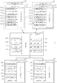
図14は、競馬ゲーム装置1のハードウェアの概略構成を示す説明図である。
FIG. 14 is an explanatory diagram showing a schematic configuration of hardware of the horse
図示されるように、本実施形態の競馬ゲーム装置1では、装置本体部2が主制御基板21を備え、各サテライト90がサテライト制御基板91を備え、各自走体30が自走体制御基板101を備えており、通信ケーブルや無線LAN回線などによって主制御基板21、各サテライト制御基板91及び各自走体制御基板101の間でのデータの送受信が可能とされている。なお、主制御基板21、サテライト制御基板91及び自走体制御基板101は、それぞれ、CPUや、ROM、RAM、ハードディスクなどの記録装置を備える情報処理装置である。
As shown in the figure, in the horse
主制御基板21には、フィールドカメラ22a、ゴールカメラ22b、モニタ装置23、天井カメラ24、スピーカ25、照明装置26、通信装置27、無線LAN装置28などが接続されており、主制御基板21は、レースの進行に合わせてこれらの装置を駆動制御するとともに、各サテライト制御基板91及び各自走体制御基板101との間で種々のデータや信号を送受信することで競馬ゲームの進行を統括的に制御するものである。
The main control board 21 is connected to a
なお、本実施形態では、主制御基板21の制御により、GIレース(Grade One Race)やGIIレース(Grade Two Race)、GIIIレース(Grade Three Race)など、複数種類のグレードで構成される36回の競馬ゲームのセットが反復して実行されるよう構成されている。
In the present embodiment, under the control of the
サテライト制御基板91には、メダル払出装置93a、タッチパネル式モニタ95、スピーカ96、メダルセンサ97a、ペイアウトボタン98、通信装置99などが接続されており、サテライト制御基板91は、各競馬ゲームの実行前の所定時間内に、遊戯者によるタッチパネル式モニタ95のベット画面BPに対する操作に基づいて、1又は複数通りの投票を受け付ける処理を実行し、上記所定時間が経過した時点で受け付けた投票についてのデータを主制御基板21に送信する処理を実行する。
Connected to the
また、サテライト制御基板91は、上記において受け付けた投票を、各競馬ゲームの終了後に主制御基板21から受信する各走行体50の着順についてのデータと対比することより当選の有無を判定し、当選している場合には、主制御基板21において定められたオッズや投票において投入されたメダルの枚数等から導かれる枚数のメダルをメダル払出装置93aから払い出すなどの処理を実行する。
In addition, the
各自走体制御基板101には、撮影制御基板102、LED制御基板103、画像処理基板(FPGA)104、画像メモリ105、走行制御基板106、模型制御基板107、無線LAN装置108などが接続されている。
An
撮影制御基板102は、カメラ装置36による撮影動作の制御を行うものであり、本実施形態では、撮影制御基板102の制御により、カメラ装置36は、1秒間に2〜200回程度の頻度で情報配置面である第2走行面7s上のQRコードを高速撮影する。
The
LED制御基板103は、白色LED37を点灯制御し、カメラ装置36の撮影に必要な照明光を情報配置面に照射する処理を実行する。
The
画像処理基板104は、カメラ装置36により撮影された各画像を走査することで、各画像に含まれる各QRコードの3頂点に配置されたマーカーを抽出する処理を実行し、また、自走体制御基板101により抽出された撮影画像中のQRコードをデコードする処理を実行する。
The
画像メモリ105は、カメラ装置36により撮影された画像を一時的に記録するものである。
The
走行制御基板106は、自走体制御基板101からの制御信号に従って走行モータ35a、35bの駆動制御を行うことにより、走路8上での自走体30の走行を制御するものである
模型制御基板107は、自走体制御基板101からの制御信号に従って駆動モータ45a〜45cの駆動制御を行うことにより、模型体57に取り付けられた可動部材76、77、80〜85を揺動駆動し、或いは、模型体57を馬体回転軸us3の周りで回転駆動するなど、模型体57の動作制御を行うものである。
The traveling
模型体制御基板107は、後述の演出信号に従って、模型体57による演出動作のために駆動モータ45a〜45cの駆動制御を実行することに加え、自走体制御基板101から正常セット信号を受信した場合には、馬模型の前後脚部76、77を揺動させる「正常セット動作」のためにの駆動磁石45bの駆動制御も実行する。
The model
自走体制御基板101は、画像処理基板104が抽出したマーカーからQRコードを抽出する処理を行うとともに、そのQRコードから取得されるグローバル座標上での位置座標と、そのQRコードのカメラ座標上での位置及び角度とに基づいて、グローバル座標上での自走体30の基準点Rの位置座標及び角度Fを特定し、当該位置座標及び角度Fを用いて主制御基板21から受信した走行データに従った正確な走行コースで自走体30を走行させるべく、走行制御基板106に所定の制御信号を送信する。
The self-propelled
また、自走体制御基板101は、ホール素子48のホール電圧によって自走体30と走行体50の位置関係を常時監視しており、何らかの原因で走行体50が自走体30から外れた場合には、所定の事故信号を主制御基板21に送信することで異常を報知するものとされている。
In addition, the self-propelled
更に、本実施形態の自走体制御基板101では、走行体50が自走体30から外れた状態から正しい位置関係にセットされた場合には、所定の正常セット信号を模型体駆動基板107に送信することにより、模型体57に前後脚部76、77を揺動させる「正常セット動作」を実行させる。
Furthermore, in the self-propelled
従って、走行体50が自走体30に対して正しい位置、方向にセットされたかどうかを、模型体57の「正常セット動作」によって直ちに確認することが可能であり、競馬ゲーム装置1の起動や事故からの復旧の際などにおける走行体50のセット作業が容易化される。
Therefore, it is possible to immediately confirm whether or not the traveling
無線LAN装置108は、所定のタイミング毎に主制御基板21において生成された走行データや演出信号を受信し、自走体制御基板101が導出する自走体30の時々刻々の基準点Rのグローバル座標上での位置座標、又は、当該位置座標及び角度Fを主制御基板21に送信するなどの処理を実行する。
The
図15は、主制御基板21においてROMやハードディスクに記録されたプログラムを実行することにより実現される機能ブロックを示す説明図である。 FIG. 15 is an explanatory diagram showing functional blocks realized by executing a program recorded on a ROM or a hard disk in the main control board 21.
図示されるように、本実施形態の競馬ゲーム装置1は、馬データ記録部111、走行パラメータ管理部112、走行データ生成部113、オッズ算出部114、着順決定部115、投票集計部116、演出処理部117の各機能構成を備えている。
As shown in the drawing, the horse
馬データ記録部111は、複数の競走馬の名称(馬名)やその属性(年齢、雌雄など)等を記録するものである。
The horse
馬名は、実在の競走馬と同一の名称を使用しても良いが、本実施形態では、現実の競馬に詳しくない遊戯者にも遊戯を楽しんで貰えるように、各競走馬にはオリジナル(架空)の馬名が使用されている。 The name of the horse may be the same as that of a real racehorse, but in this embodiment, each racehorse is original ( A fictional horse name is used.
馬データ記録部111には、トラック5上に配置される走行体50の台数(例えば、6〜12)と同数の競走馬についての馬データを記録しても良いが、それよりも多数(例えば、100頭)の競走馬についての馬データを記録しておけば、レース毎に異なる競走馬を出走させる(走行体50に割り当てる)ことにより、レースの多様性を高めることができる。
The horse
走行パラメータ管理部112は、走行データ生成部113における着順やレース展開(走行データ)の決定に使用される能力パラメータを記録するものである。
The running
図16は、本実施形態の走行パラメータ管理部112に記録される例示的な能力パラメータを示す説明図である。
FIG. 16 is an explanatory diagram illustrating exemplary capability parameters recorded in the travel
本実施形態では、レース番号「1」〜「8」のレースを反復して実行するようになっており、図示のように、走行パラメータ管理部112には各レースについての各競走馬の能力パラメータが記録されている。なお、能力パラメータの最小値は「10」、最大値は「80」であり、能力パラメータが空欄の部分は、当該レースに当該競走馬が出走しないことを示している。また、図中のIDは、馬データ記録部に記録される各競走馬に割り当てられた識別符号である。
In the present embodiment, the races with race numbers “1” to “8” are repeatedly executed. As shown in the figure, the running
そして、競走馬「アローフィールド」については、後半のレースほど能力パラメータが大きくなるように、競走馬「ラプラスダイス」については、後半のレースほど能力パラメータが小さくなるように能力パラメータの設定がなされており、これにより、現実の競走馬がレースを重ねるうちに成長したり、弱くなっていくなどの様子が模擬されている。 For the racehorse “Arrowfield”, the ability parameter is set so that the ability parameter becomes larger in the latter half of the race, and for the racehorse “Laplace Dice”, the ability parameter becomes smaller in the latter half of the race. This simulates how real racehorses grow and become weaker as they race.
また、競走馬「マッハワン」については、全てのレースについて能力パラメータの最大値である「80」が設定されている。 For the racehorse “Mach One”, “80”, which is the maximum value of the ability parameter, is set for all races.
走行データ生成部113は、トラック5上に配置される各走行体50に馬データ記録部111に記録されるいずれかの競走馬を割り当てるとともに、走行パラメータ管理部112に記録される各競走馬の能力パラメータに基づいて、各走行体50の着順を決定する処理を実行する。
The travel
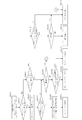
図17は、各レース開始前の所定のタイミングにおいて走行データ生成部113により実行される着順決定処理の流れを示すフローチャートである。
FIG. 17 is a flowchart showing a flow of an arrival order determination process executed by the running
当該着順決定処理では、着順値Rを「1」に設定するなどの初期化処理(ステップS101)が行われた後に、各走行体50に割り当てられた全ての競走馬の能力パラメータをパラメータ管理部112から取得する処理が実行される(ステップS102)。
In the arrival order determination process, after the initialization process (step S101) such as setting the arrival order value R to “1” is performed, the ability parameters of all the racehorses assigned to each traveling
続くステップS103では、当該ステップS103の実行時点において着順が未決定の競走馬(以下、「着順未決定馬」という)の能力値の合計値Tが算出され、更にステップS104では、各着順未決定馬にそれぞれの能力パラメータの値に応じた広さの相互に重複しない数値範囲を割り当てる処理が実行される。 In the subsequent step S103, the total value T of the ability values of the racehorses whose arrival order has not been determined at the time of execution of the step S103 (hereinafter referred to as “arrival order undecided horse”) is calculated. A process of assigning numerical ranges not overlapping each other to the undecided horses according to the value of each ability parameter is executed.
図18は、本実施形態における合計値Tの算出及び数値範囲の割り当ての態様を示す説明図である。 FIG. 18 is an explanatory diagram showing how the total value T is calculated and the numerical value range is assigned in the present embodiment.
今、対象レースが図16の符号Xで示されるレースであり、ステップS103、S104の実行時点における着順未決定馬が「アローフィールド(ID:A)」、「マッハワン(ID:B)」及び「ラプラスダイス(ID:C)」の3頭であるとすると、ステップS103では、これら3頭に割り当てられた能力パラメータを合計することにより合計値T(180=70+80+30)が算出される。 Now, the target race is the race indicated by the symbol X in FIG. 16, and the arrival order undecided horses at the time of execution of Steps S103 and S104 are “Arrow Field (ID: A)”, “Mach One (ID: B)” and Assuming that there are three “Laplace dice (ID: C)”, the total value T (180 = 70 + 80 + 30) is calculated in step S103 by summing up the ability parameters assigned to these three.
そして、ステップS104では、IDが先頭の「アローフィールド」にはその能力パラメータ「70」と同数(70個)の数値を含む「1〜70」の数値範囲が割り当てられ、次の「マッハワン」には能力パラメータ「80」と同数の数値を含む「71〜150」の数値範囲が割り当てられ、「ラプラスダイス」には能力パラメータ「30」と同数の数値を含む「151〜180」の数値範囲が割り当てられる。 In step S104, a numerical range of “1 to 70” including the same number (70) of numerical values as the capability parameter “70” is assigned to the “arrow field” having the head ID, and the next “Mach one” is assigned. Is assigned a numerical range of “71 to 150” including the same number as the ability parameter “80”, and “Laplace Dice” has a numerical range of “151 to 180” including the same number as the ability parameter “30”. Assigned.
続くステップS105では、1〜合計値T(上の例では「180」)の範囲で乱数を発生する処理が実行され、発生させた乱数を含む数値範囲を割り当てられた競走馬が抽選され、その時点における着順値Rが当該抽選された競走馬の着順として決定される。 In the subsequent step S105, a process of generating random numbers in the range of 1 to the total value T (“180” in the above example) is executed, and racehorses assigned with a numerical range including the generated random numbers are drawn, The arrival order value R at the time is determined as the arrival order of the lottery racehorses.
続くステップS106では、ステップS105において抽選された競走馬を着順未決定馬から除外することにより着順未決定馬の更新が実行される。 In the subsequent step S106, the racehorse selected in step S105 is excluded from the horses that have not yet arrived in order of arrival, thereby updating the horses that have not yet arrived.
ステップS107では、更新された着順未決定馬の頭数が1頭であるか否かの判定が実行され、2頭以上である場合には、着順値Rに「1」を加算する処理(ステップS108)が実行された後に処理はステップS103に復帰し、1頭である場合には、その競走馬の着順を最終着に決定する処理(ステップS109)が行われて着順決定処理は完了となる。 In step S107, it is determined whether or not the number of updated arrival order undecided horses is one. If there are two or more, the process of adding “1” to the arrival order value R ( After step S108) is executed, the process returns to step S103. If there is one, the process for determining the racehorse arrival order as the final arrival (step S109) is performed, and the arrival order determination process is as follows. Completed.
本実施形態では、上記態様の着順決定処理により各競走馬の着順が決定されるため、能力パラメータが高い競走馬である程、上位の着順(1、2、3着等)が決定される確率が高く、能力パラメータが低い競走馬である程、下位の着順(8、9、10着等)が決定される確率が高くなる。 In this embodiment, since the arrival order of each racehorse is determined by the arrival order determination process of the above aspect, the higher arrival order (1, 2, 3, etc.) is determined for a racehorse having a higher ability parameter. The higher the probability of a racehorse having a lower ability parameter, the higher the probability that the lower order of arrival (8, 9, 10, etc.) will be determined.
走行データ生成部113は更に、上記により決定された着順に基づいて、レース開始からゴールまでの経過時間に対する各自走体30の走路8上における位置座標を規定する走行データを生成する。
The travel
オッズ算出部114は、各走行体50に割り当てられた競走馬の能力パラメータに基づいて、全ての指定態様における全ての着順についてオッズを算出する。
The
ここで、本実施形態におけるオッズは、1枚のメダルを対価として投票を行った場合に配当として払い出されるメダル枚数の期待値がペイアウト率(払戻率。配当として払い出される総メダル数を全ての投票における対価とされた総メダル数で除した値)と等しくなるように設定された配当割合(配当倍率)である。 Here, the odds in the present embodiment are that the expected value of the number of medals to be paid out as a payout when voting with one medal as the payout is the payout rate (refund rate. The total number of medals to be paid out as the payout Is a payout ratio (payout rate) set to be equal to (the value divided by the total number of medals taken as a consideration).
着順決定部115は、各自走体30から無線LAN装置28を介して各自走体30の時々刻々の第2走行面7s上における位置座標を受信し、各レースにおいて各自走体30がゴール5cに到着した時刻の先後により着順を決定する。ここで、走行データ生成部113において生成した走行データに基づいて着順を決定するのではなく、現実の自走体30の走行に基づいて着順を決定するものとしたのは、何らかの原因により走行データと異なる着順で各自走体30がゴールした場合におけるトラブル等の発生を回避するためである。
The arrival
投票集計部116は、各サテライト90において受け付けられた投票についてのデータを各サテライト90から受信してこれを集計する処理を実行する。
The
演出処理部117は、走行パラメータ管理部112において記録される能力パラメータ、着順決定部115により決定された競馬ゲームにおける着順、投票集計部116における投票の集計結果などに基づいて所定の演出信号を生成し、これを対象の自走体30に送信する処理を実行する。
The
具体的には、演出処理部117は、各サテライト90において各競馬ゲームについての投票受付が開始される前の所定のタイミングで、その競馬ゲームに出走する各競走馬の能力パラメータを検査し、いずれかの競走馬の能力パラメータが所定値(例えば70)以上である場合には、その競走馬が割り当てられた自走体30に対して、競走馬の好調をアピールする「好調演出」の実行を指示する演出信号を送信する。
Specifically, the
「好調演出」の演出信号を受信した自走体30では、模型制御基板107の制御の下で模型制御モータ46cが駆動磁石45cを所定の態様で回転駆動し、この回転力が馬体回転機構(図12(a))を介して馬模型58に伝達されことにより、馬模型58は、所定の時間に渡って、図19(a)に示す態様で馬体を円柱状突起us3の周りに回転させて「後脚立ち姿勢」を取る「好調演出」を実行する。
In the self-propelled
なお、この演出信号が送信される時点では、各走行体50はスタート地点5a又は5bにおいてゲートイン待ちの状態にあり、各サテライト90の遊戯者は、ゲートイン待ちのどの馬模型58が「後脚立ち姿勢」をとるかを参考に投票を行うことが可能である。
At the time when this effect signal is transmitted, each traveling
また、演出処理部117は、投票集計部116における集計が終了した時点で、各サテライト90における投票で人気の高かった競走馬が割り当てられた自走体30に対して、多くの投票を受けて奮起していることをアピールする「奮起演出」の実行を指示する演出信号を送信する。なお、投票での人気の高さを評価する方法は種々考えられるが、本実施形態では、3台以上のサテライト90で、最も多数のメダルを対価とした投票において指定された競走馬が「奮起演出」の対象として選択される。
In addition, when the counting in the
「奮起演出」の演出信号を受信した自走体30では、模型制御基板107の制御の下で模型制御モータ46aが駆動磁石45aを所定の態様で回転駆動し、この回転力が騎手駆動機構(図11(a))を介して騎手模型59に伝達されることにより、騎手模型59は、その姿勢を図11(b)ついて説明した第3姿勢(C)と第4姿勢(D)の間で反復して変化させるよう駆動され、その結果、図19(b)に示すように、騎手が馬上で立ち上がって歓声に応えている動作が模擬される。
In the self-propelled
なお、この演出信号が送信される時点では、各走行体50はスタート地点5a又は5bにおいてゲートインの状態にあり、多くの投票を獲得した競走馬に対応する走行体50において、競馬ゲームの直前に上記態様の「奮起演出」が実行されるため、その競走馬に投票した遊戯者の期待感や満足感を高めるなどの効果を得ることができる。
At the time when this effect signal is transmitted, each traveling
また、演出処理部117は、着順決定部115が各競馬ゲームにおける着順の決定を行った時点で、その競馬ゲームにおいて勝利した走行体50に対応する競走馬がいずれかのサテライト90での投票において指定されていたことを条件として、その勝利した走行体50に対応する自走体30に対して、その投票を受け付けたサテライト90に割り当てられたサテライト対応領域8a〜8l内において、多くの投票を受けて勝利できたことに感謝していることをアピールする「感謝演出」の実行を指示する演出信号を送信する。
In addition, when the arrival
「感謝演出」の演出信号を受信した自走体30は、走行制御基板106の制御により走行モータ35a、35bを駆動して、演出信号により指示されるサテライト対応領域8a〜8lに自走体30を移動させ、その後、模型制御基板107の制御により模型制御モータ46a及び46cが駆動磁石45a及び45cを所定の態様で回転駆動し、これが騎手駆動機構(図11(a))及び馬体回転機構(図12(a))を介して馬模型58及び騎手模型59に伝達されることにより、「後脚立ち姿勢」を取った馬模型58上で、騎手模型59がその姿勢を第3姿勢(C)と第4姿勢(D)の間で反復して変化させるよう駆動され、その結果、図19(c)に示すように、人馬が一体となって感謝乃至歓喜している様子が模擬される。
The self-propelled
このように、遊戯者が投票において指定した競走馬が勝利した場合には、対応する走行体50が、トラック5上をその遊戯者のいるサテライト90に最も近い位置まで近づいて上記態様の「感謝演出」を実行するため、「感謝演出」がその遊戯者のための演出であることを理解して貰うことが可能であり、投票が当選となったことに対する遊戯者の満足感を高め、或いは、次回以降の競馬ゲームでの投票に対する意欲を高揚させるなどの効果を期待することができる。
Thus, when the racehorse designated by the player in the voting wins, the corresponding traveling
図20(a)、(b)は、上記第1の実施形態における馬模型58の可動部材である前脚部76を駆動する馬体駆動機構の変形形態を示す説明図であり、図20(a)には、馬フレーム70周辺を左方から示す側面図が示されており、図20(b)には、馬フレーム70周辺を上方から示す平面図が示されている。
20A and 20B are explanatory views showing a modified form of the horse drive mechanism that drives the
なお、図20(a)、(b)においては、図5〜図12と共通の要素には同一の符号が付されている。 In FIGS. 20A and 20B, the same reference numerals are given to elements common to FIGS.
図示のように、この変形形態においても、馬脚駆動軸63先端のウォーム63aに歯合する歯車ユニットug3等が組み込まれたウォームギアボックスと、牽引シャフト66aが取り付けられた牽引部材66が馬フレーム70、70間の馬体空間に内挿されており、馬フレーム70、70の概略中央部には、ウォームギアボックス65の円柱状突起us3を枢着する軸孔70aと、円柱状突起us4を案内する円弧状のガイド孔70bが穿孔され、その後方位置には駆動部材66の牽引シャフト66aを枢着する駆動孔72dが穿孔されている。
As shown in the figure, also in this modification, the worm gear box in which the gear unit ug3 and the like meshing with the
従って、この変形形態においても、駆動磁石45cの回転を制御することにより、馬模型58を円柱状突起us3の回りに回転駆動することが可能である。
Therefore, also in this modification, the
また、馬フレーム70、70間には、4本のシャフトs1〜s4がそれぞれの軸芯回りに回転自在に差し渡されており、シャフトs1には、平歯車g1及びハスバ歯車g3が一体に取り付けられるとともに、時計回り方向(図20(a)の矢印Aに示す方向)の回転のみを伝達するクラッチ機構を介して平歯車g1に連結された平歯車g2が軸挿されている。 In addition, four shafts s1 to s4 are passed between the horse frames 70 and 70 so as to be rotatable around their respective axis, and a spur gear g1 and a helical gear g3 are integrally attached to the shaft s1. At the same time, a spur gear g2 connected to the spur gear g1 is inserted through a clutch mechanism that transmits only the rotation in the clockwise direction (the direction indicated by the arrow A in FIG. 20A).
シャフトs2は、シャフトs1の前側上方において馬フレーム70、70を貫通して取り付けられており、馬フレーム70、70の内側においては平歯車g2と歯合する平歯車g4が、馬フレーム70、70の外側においては、クランク板121を介在させて平歯車g5及び回転盤部材75が、それぞれシャフトs2に一体に取り付けられている。
The shaft s2 is attached through the horse frames 70, 70 in the upper front side of the shaft s1, and a spur gear g4 that meshes with the spur gear g2 is provided inside the horse frames 70, 70. The spur gear g5 and the
シャフトs3は、シャフトs2の前方位置において馬フレーム70に突設された軸受b1に水平方向(図20(b)の矢印C、Dに示す方向)への並進移動可能に枢着されている。シャフトs3には、ハスバ歯車g3と歯合するハスバ歯車g6が一体に取り付けられており、ハスバ歯車g3が反時計回り方向に回転した場合には、右方向(矢印C方向)に、ハスバ歯車g3が時計回り方向(B方向)に回転した場合には、左方向(矢印D方向)に向かうスラスト力が発生するようになっている。シャフトs3には更に、反時計回り方向の回転のみを伝達するクラッチ機構を介してハスバ歯車g6に連結され、平歯車g4に歯合する平歯車g7が枢着されている。
The shaft s3 is pivotally attached to a bearing b1 protruding from the
シャフトs4は、シャフトs3の更に前方位置において馬フレーム70に突設された軸受b2に水平方向への並進移動可能に枢着されており、図20(c)に示すように、その両端には、軸芯から外方に向けて伸びるカム片s4aが取り付けられている。
The shaft s4 is pivotally attached to a bearing b2 protruding from the
また、シャフトs4の外周には、シャフトs4とともに水平方向に並進移動するハウジング122が取り付けられている。ハウジング122は、シャフトs4を回転可能に収容する円筒部122aと、円筒部122aから垂下した2枚の側壁122b、122cとから構成されており、2枚の側壁122b、122c間にハスバ歯車g6及び平歯車g7が収容されるようになっている。
A
シャフトs4には更に、馬フレーム70、70の外側において、平歯車g5と歯合する平歯車g8が一体に取り付けられており、当該平歯車g8には、カム片s4aと相補的な形状の開口g8aが形成され、シャフトs4の並進運動によるカム片s4aの出没が可能となっている。 Further, a spur gear g8 that meshes with the spur gear g5 is integrally attached to the shaft s4 outside the horse frames 70 and 70, and the spur gear g8 has an opening that is complementary to the cam piece s4a. g8a is formed, and the cam piece s4a can be moved in and out by translational movement of the shaft s4.
図20(d)、(e)には、それぞれ、クランク板121の表裏面が示されている。
20D and 20E show the front and back surfaces of the
図示のように、クランク板121は、上方の円盤状部分と下方の台形状部分とから構成される平板状の部材であり、円形状部分の中心には軸孔121aが穿孔されるとともに、前方に向かって当接片121bが設けられており、台形状部分の前方側には軸孔121cが、後方側には馬フレーム70に取り付けられるスプリング123による後方への付勢力を受ける係止部121dが突設されており、その裏面側には馬フレーム70に穿孔された不図示の案内溝に案内されるガイドピン121eが突設されている。
As shown in the figure, the
前脚部76は、上記した実施形態における前脚部76と実質的に同一の構成を有しているが、その中央付近に内側に向けて突設された揺動軸76dは、クランク板121の軸孔121cに枢着され、その上端の長穴76aには回転盤部材75の偏心位置に突設されたガイドピン75cが挿通される。
The
なお、この変形形態においても、ウォームギアボックス65には、騎手駆動軸62先端のウォーム62a及びその回転力を伝達する歯車ユニットug7、平歯車ug4等が取り付けられており、更に、馬フレーム70、70の内側には、平歯車ug4の回転力を騎手模型59に伝達する平歯車mg4〜mg6等が取り付けられているが、図20(b)ではこれらの部材は省略されている。
Also in this modified embodiment, the
図21は、上記変形形態に係る馬体駆動機構において、馬脚駆動軸63を逆方向に回転させたときの前脚部76の揺動の態様を示す説明図である。
FIG. 21 is an explanatory view showing a manner of swinging of the
図21(A)の状態を初期姿勢と呼ぶものとすると、初期姿勢(A)においては、回転盤部材75はガイドピン75cが軸芯75aの直上となる回転位置にあり、前脚部76は概略鉛直下方に垂下した状態にある。
If the state of FIG. 21A is called an initial posture, in the initial posture (A), the
この初期姿勢(A)から、馬脚駆動軸63が逆方向に回転することで平歯車g1は反時計回り方向に回転し、その回転はクラッチ機構を介して平歯車g2に伝達され、これに歯合する平歯車g4が時計回りに回転し、平歯車g4と一体にシャフトs2に取り付けられた回転盤部材75が時計回りに回転することになる。
From this initial posture (A), when the horseshoe
これにより、回転盤部材75の偏心位置にあるガイドピン75cは、前脚部76の長穴76a内を下方に移動し、前脚部76は揺動軸76dの周りで前方に向けて回転駆動され、ガイドピン75cが長穴76aの中間における特定位置に達したところで馬体駆動機構は、前脚部76が最も前方に回転した開脚状態(B)となる。
As a result, the
開脚状態(B)から回転盤部材75が更に回転すると、ガイドピン75cが長穴76a内を更に下降するにつれて前脚部76は後方に向けて回転し、やがては前脚部76が初期姿勢(A)と同一の角度となる初期姿勢(C)に戻る。
When the
そして、初期姿勢(C)から更に回転盤部材75が回転すると、ガイドピン75cは長穴76aの最下点を通過して上昇していくことになり、これにより、前脚部76は揺動軸76dの周りで更に後方に向けて回転駆動されていき、ガイドピン75cが長穴76aの中間における特定位置に達したところで馬体駆動機構は、前脚部76を最も後方に回転させた閉脚姿勢(D)となる。
When the
回転盤部材75が更に回転すると、やがては馬体駆動機構は初期姿勢(A)に復帰し、その後は(A)〜(D)のサイクルが反復する。
When the
なお、上記サイクルでは、ハスバ歯車g3が平歯車1とともに反時計回り方向に回転し、これと歯合するハスバ歯車g6がスラスト力によって右方向(C方向)に並進移動し、平歯車g7が側壁122bに当接することでハウジング122及びシャフトs4を右方向に並進移動させる。このため、カム片s4aは平歯車g8の開口g8a内に収納され、平歯車g8が回転することによるクランク板122の駆動は行われないことになる。
In the above cycle, the helical gear g3 rotates counterclockwise together with the
また、平歯車g7は、クラッチ機構によりハスバ歯車g6との連結が遮断されているために、シャフトs3の周りでフリーに回転できる状態にあり、前脚部76の運動には何ら影響を与えない。
Further, since the spur gear g7 is disconnected from the helical gear g6 by the clutch mechanism, the spur gear g7 can be freely rotated around the shaft s3 and does not affect the movement of the
図22は、上記変形形態に係る馬体駆動機構において、馬脚駆動軸63を正方向に回転させたときの前脚部76の揺動の態様を示す説明図である。
FIG. 22 is an explanatory view showing a manner of swinging of the
馬脚駆動軸63が正方向に回転した場合、ハスバ歯車g3が平歯車1とともに時計回り方向に回転し、これと歯合するハスバ歯車g6が反時計回り方向に回転することとなり、平歯車g7は、クラッチ機構を介してハスバ歯車g6と一体となって反時計回り方向に回転する。
When the horse
このため、平歯車g7と歯合する平歯車g4及びこれと一体にシャフトs2に取り付けられた回転盤部材75は、馬脚駆動軸63が逆方向に回転した場合と同様、時計回り方向に回転することになる。
For this reason, the spur gear g4 meshed with the spur gear g7 and the
一方、ハスバ歯車g3の時計回り方向への回転により生じるスラスト力によって、ハスバ歯車g6は左方向に並進移動し、側壁122cに当接することでシャフトs4を左方向に並進移動させる。このため、馬脚駆動軸63が正方向に回転している間は、カム片s4aは、平歯車g8の開口g8aから左方に突出した状態に保たれることになる。また、シャフトs2に固定された平歯車s5は、平歯車g4とともに時計回り方向に回転するため、この平歯車s5に歯合する平歯車s8及びこれに固定されたシャフトs4は反時計回り方向に回転し、これにより、カム片s4aは、開口g8aから突出した状態で、シャフトs4の周りで反時計周り方向に回転することになる。
On the other hand, the thrust force generated by the clockwise rotation of the helical gear g3 causes the helical gear g6 to translate in the left direction and contact the
今、回転盤部材75がガイドピン75cを軸芯75aの直上とした回転位置にあり、前脚部76は概略鉛直下方に垂下した状態(A)を初期姿勢と呼ぶものとすると、この初期姿勢(A)から馬脚駆動軸63が正方向に回転すると、図21について上記したと同様に、回転盤部材75のガイドピン75cによる駆動を受けて、前脚部76は揺動軸76dの周りで前方に向けて回転駆動されていくが、その過程で、反時計回り方向に回転するカム片s4aが当接片121bに係合することとなり(A′)、カム片s4aの回転によりクランク板121は、スプリング123の付勢力に抗して軸孔121aの周りで時計回り方向に回転することになる。
Now, assuming that the
このために、クランク板121の軸孔121cは、前方に向けて移動し、これに軸支される揺動軸76dの馬フレーム70上における位置も前方に向けて移動することになる。
For this reason, the
そして、揺動軸76dの馬フレーム70上における位置が最も前方まで移動したところで、馬体駆動機構は、前脚部76が最も前方に回転した開脚状態(B)となる。
Then, when the position of the
開脚状態(B)から更に回転盤部材75が回転すると、カム片s4aと当接片121bの係合が外れ、スプリング123の付勢力によって、軸孔121c及び揺動軸76dの馬フレーム70上における位置は初期状態(A)と同一の位置に復帰する。
When the
その後は、図21について上記したと同様の態様で、可動部材駆動機構は初期姿勢(C)及び閉脚姿勢(D)を経て初期姿勢(A)に復帰し、更に、(A)〜(D)のサイクルが反復する。 Thereafter, in the same manner as described above with reference to FIG. 21, the movable member drive mechanism returns to the initial posture (A) through the initial posture (C) and the closed leg posture (D), and (A) to (D). The cycle repeats.
このように、本変形形態に係る馬体駆動機構では、馬脚回転軸63を逆回転させることにより、馬模型58上における揺動軸76dの位置を移動させることなく前脚部76を前後に揺動させることが可能であり、馬脚回転軸63を正回転させた場合には、前脚部76を前後に揺動させるとともに、前脚部76の前方への揺動に同期して、その揺動軸76dの馬模型58上における位置を前方に移動させることが可能である。
Thus, in the horse drive mechanism according to this modification, the
従って、馬脚回転軸63を逆回転させることで比較的静かな態様で前脚部76を揺動させ、競走馬が低速で走行している様子を模擬することが可能であり、馬脚回転軸63を正回転させることで高い躍動感をもって前脚部76を揺動させ、競走馬が高速で走行している様子を模擬することが可能である。
Therefore, by rotating the horse
図23は、本発明の第2の実施形態に係るゲーム装置に使用される馬模型158の構成を示す説明図であり、図23(a)には、主として1対の馬フレーム170の外側に取り付けられる部材が、図23(b)には、肩部材173の形状の詳細が、図23(c)には、主として1対の馬フレーム170の内側に収容される部材が示されている。
FIG. 23 is an explanatory view showing a configuration of a
図23(a)に示されるように、この馬模型58は、顔部材179、首部材178、肩部材173、前脚部176、回転盤部材175等を馬フレーム170の外側に備えている。首部材178の内側には、2本のシャフト178a、178bが突設されており、その一方のシャフト178aは馬フレーム170に穿孔された軸孔170aに枢着され、首部材178は軸孔170aの回りで回転自在となっている。また、顔部材179の内側には、2本のシャフト179a、179bが突設されており、その一方のシャフト179aは首部材179の先端に穿孔された軸孔179cに枢着され、首部材178は、軸孔178cの回りで回転自在となっている。
As shown in FIG. 23A, the
図23(b)に示されるように、肩部材173は、本体から下方にカバー173a及びアーム173bを垂下させた立体的な部材であり、カバー173aとアーム173bの間には、前脚部176の上端を前方から挿通させて収容するスペースが形成されている。肩部材173の本体中央及びアーム173bには、それぞれ軸孔173c、173dが形成され、本体上部には、首部材の後部壁178dを押圧する押圧ピン173eが突設されている。肩部材173は、本体中央の軸孔173cを馬フレーム170の前端に突設されたシャフト170bに枢着されて馬フレーム170に対して揺動自在とされている。
As shown in FIG. 23B, the
前脚部176は、その上端部をカバー173aとアーム173bの間のスペースに遊挿させるとともに、その概略中央に内側に向けて突設された揺動軸176dにおいて肩部材173の軸孔173dに揺動自在に軸支される。
The
前脚部176の上部には、長穴176aが形成されており、当該長穴176aには、後述の螺子歯車ug8に歯合する不図示のギヤ列を介して回転駆動される回転盤部材175の偏心位置に外側に向けて突設されたガイドピン175cが遊挿される。
A
図23(c)に示されるように、馬フレーム170の内側には、馬脚駆動軸163と、その上端に一体に取り付けられたウォーム163aと、ウォーム163aに歯合する2つの歯車ユニットug8、ug9と、歯車ユニットug8に歯合するラック180が取り付けられており、ラック180の上端に形成された開口には、首部材178のシャフト178bが枢着されている。
As shown in FIG. 23 (c), on the inner side of the
また、そのシャフト178bには、首骨部材181の下端に形成された開口が挿通され、首骨部材181の上端に形成された開口には、顔部材179のシャフト179aが枢着されている。
An opening formed at the lower end of the
ここで、馬脚駆動軸163及びウォーム163aは、第1の実施形態における馬脚駆動軸63及びウォーム63aと実質的に同様の部材であり、従動磁石55bに駆動されて一体となって回転する。また、歯車ユニットug8、ug9は、第1の実施形態における歯車ユニットug3と同様、一体に形成された螺子歯車と平歯車から構成され、ウォーム163aの回転力を、それぞれラック180及び不図示の歯車列に伝達する。
Here, the horse
図24(a)、(b)は、第2の実施形態において、従動磁石55bの駆動により、馬脚駆動軸163を正方向に回転させた場合の馬模型58の動作態様を示す説明図である。
FIGS. 24A and 24B are explanatory views showing an operation mode of the
馬脚駆動軸163を正方向に回転させた場合、歯車ユニットug9は、図24(c)の方向から見て時計回り方向に回転し、不図示の歯車列を介して回転盤部材175を時計回り方向に回転させる。
When the horse
今、馬模型58は図24(a)の状態にあるものとする。なお、この状態では、首部材178は、その後部壁178dが肩部材173の押圧ピン173eの当接による付勢力によって持ち上げられて、フリーの状態からシャフト178aの周りで前方乃至上方に向けて回転した状態にある。
Now, it is assumed that the
この状態から回転盤部材175が時計回り方向に回転すると、その偏心位置にあるガイドピン175cが前脚部176の長穴176a内を下方に移動し、これにより、前脚部176は揺動軸176dの周りで前方に向けて回転駆動される。
When the
このとき、揺動軸176dがガイドピン175cから前方に向かう付勢力を受けるために肩部材173が軸孔173cの周りを前方に向けて回転し、揺動軸176dは前方に向けて、押圧ピン173eは後方に向けて移動していくことになる。
At this time, since the
図24(b)は、回転盤部材175により前脚部176が最も前方に回転した状態であり、この状態において揺動軸176dは最も前方に位置し、押圧ピン173eは首部材178から完全に離間し、首部材178は自重により最も後方乃至下方に回転したフリーの状態にある。
FIG. 24B shows a state in which the
そして、回転盤部材175が更に回転すると、上記とは逆に、ガイドピン175cが長穴176a内を上方に移動することで、前脚部176及び肩部材173は、それぞれ揺動軸176d及び軸孔173cの周りを後方に向けて回転し、押圧ピン173eが首部材178の後部壁178dに当接した以降は、押圧ピン173eの付勢力により首部材178を前方乃至上方に向けて回転させ、やがては図24(a)の状態に復帰する。
When the
なお、馬脚駆動軸163を正方向に回転させた場合、歯車ユニットug8は、図24(c)の方向から見て反時計回り方向に回転し、その回転によってラック180は歯車ユニットug8と歯合しない下端位置まで下降する。従って、歯車ユニットug8及びラック180は、この場合の馬模型58の動作に影響しない。
When the
図24(c)、(d)は、第2の実施形態における従動磁石55bの駆動により、馬脚駆動軸163を逆方向に回転させた場合の馬模型58の動作態様を示す説明図である。
FIGS. 24C and 24D are explanatory views showing an operation mode of the
馬脚駆動軸163を逆方向に回転させた場合、歯車ユニットug8は、図24(c)の方向から見て時計回り方向に回転し、歯車ユニットug8と歯合するラック180が歯車ユニットug8の回転により上方に向けて移動するために、シャフト178b、179bがそれぞれ上方に向けて駆動され、首部材178及び顔部材179は、それぞれ、シャフト178a、179aを中心に上方に向けて回転することになる。
When the horse
従って、馬脚駆動軸163を正方向に回転させることにより、馬模型58の姿勢を図24(c)の状態から、首部材178及び顔部材179を大きく上方に回転させた図24(d)の姿勢に移行させることができる。
Accordingly, by rotating the horse
なお、馬脚駆動軸163を逆方向に回転させた場合には、回転盤部材175は反時計回り方向に回転することになるが、これによる肩部材173及び前脚部176の揺動の態様は、回転盤部材175を時計回り方向に回転させた場合と順序が逆になるだけで、図24(a)、(b)について上記したと実質的に同様である。ただし、首部材178が図24(d)のように、大きく上方に回転しているために押圧ピン173eは首部材178から大きく離間し、押圧ピン173eによる首部材178の揺動は行われない。
When the horse
以上のように、本実施形態における馬模型58では、従動磁石55bの回転によって馬脚駆動軸163を回転させることにより、その回転方向に関わらず、馬模型58上における揺動軸176dの位置が前後に移動し、これに同期してその揺動軸176dの周りで前脚部176が前後に揺動するように構成されているため、現実の競走馬が高速で走行しているときのような躍動感のある走行態様を模擬することが可能である。
As described above, in the
また、馬脚駆動軸163を正方向に回転させた場合には、上記前脚部176の動作と同期して、首部材178を前後乃至上下に揺動させることが可能であり、これによって、一層高い現実感をもって競走馬の走行体用を模擬することが可能である。
Further, when the horse
更に、馬脚駆動軸163を逆方向に回転させた場合には、首部材178及び顔部材179を上方に向けて大きく回転上昇させて、現実の競走馬の嘶きの動作を模擬することが可能である。
Further, when the horse
以下、上記第2の実施形態に係るゲーム装置において実行される各種演出の具体的な一態様について説明する。 Hereinafter, specific modes of various effects executed in the game device according to the second embodiment will be described.
なお、第2の実施形態におけるゲーム装置は、第1の実施形態における馬体駆動機構(図10)に代えて、図23、24に示した馬体駆動機構を有するとともに、第1の実施形態と同様の騎手駆動機構(図11)を有し、第1の実施形態における馬体回転機構(図12)を有さない。 Note that the game device in the second embodiment has the horse drive mechanism shown in FIGS. 23 and 24 instead of the horse drive mechanism (FIG. 10) in the first embodiment, and the first embodiment. The jockey drive mechanism (FIG. 11) is the same as in FIG. 11, and the horse rotation mechanism (FIG. 12) in the first embodiment is not provided.
図25は、第2の実施形態に係る競馬ゲーム装置において各レースの開始前に実行される第1演出処理の流れを示すフローチャートである。 FIG. 25 is a flowchart showing the flow of the first effect process executed before the start of each race in the horse racing game apparatus according to the second embodiment.
図示のように、この処理では、ステップS201において、当該レースに出走する各競走馬の能力パラメータが走行パラメータ管理部112から取得され、続くステップS202では、第1設定値Th1(例えば、「70」)以上の能力パラメータを有する競走馬が検索される。そして、そのような競走馬が検索された場合(ステップ202:有り)には、ステップS203において各サテライト90において受け付けられた投票がチェックされ、更にステップS204では、ステップS202で検索された競走馬に所定数(例えば、単勝で「100枚」)以上のメダルを対価とする投票が行われたサテライト90が検索される。
As shown in the figure, in this process, in step S201, the ability parameter of each racehorse running in the race is acquired from the running
そして、ステップS204で上記条件を満たすサテライトが検索された場合には、(ステップS204:有り)、ステップS202で検索された競走馬がステップS204で検索されたサテライト90の前に移動し(ステップS205)、その競走馬の騎手がガッツポーズをする様子を模擬した「ガッツポーズ演出」が実行される(ステップS206)。
When a satellite satisfying the above conditions is searched in step S204 (step S204: present), the racehorse searched in step S202 moves in front of the
具体的には、ステップS205の処理では、上記競走馬に対応する自走体30を上記サテライト90に割り当てられたサテライト対応領域8a〜8lに移動させ、ステップS206では、その自走体30に「ガッツポーズ演出」の実行を指示する演出信号を送信する。
Specifically, in the process of step S205, the self-propelled
この演出信号を受信した自走体30では、模型制御基板107の制御の下で模型制御モータ46aが駆動磁石45aを所定の態様で回転駆動し、この回転力が騎手駆動機構を介して騎手模型59に伝達されることにより、騎手模型59は、その姿勢を図11(b)における第3姿勢(C)と第4姿勢(D)の間で反復して変化させるよう駆動され、その結果、図26(a)に示すように、馬上で立ち上がった騎手が手を上げてガッツポーズを行う様子を模擬した「ガッツポーズ演出」が実行される。
In the self-propelled
一方、上記ステップS202において、第1設定値Th1以上の能力パラメータの競走馬が検索されなかった場合(ステップS202:無し)には、処理はステップS207に移行して、第1設定値Th1よりも小さい第2設定値Th2(例えば、「60」)以上の能力パラメータを有する競走馬の検索が行われる。 On the other hand, in the above step S202, when a racehorse having a capability parameter equal to or greater than the first set value Th1 is not searched (step S202: none), the process proceeds to step S207, and the process proceeds to a step greater than the first set value Th1. A search for racehorses having a capability parameter equal to or greater than a small second set value Th2 (for example, “60”) is performed.
ステップS207において、第2設定値Th2以上の能力パラメータの競走馬が検索された場合(ステップS207:有り)、又は、ステップS204において上記条件を満たすサテライト90が検索されなかった場合(ステップS204:無し)には、ステップS208において、所定の当選確率(例えば、1/2)での抽選処理が実行される。
In step S207, when a racehorse having an ability parameter equal to or greater than the second set value Th2 is searched (step S207: present), or in case where a
そして、上記ステップS208の抽選の結果が当選であった場合には(ステップS208:当選)、ステップS209において、ステップS205又はステップS210の処理が実行される競走馬が他に有るか否かが判定され、無い場合(ステップS209:NO)には、ステップS202又はS207で検索された競走馬についての「嘶き+ガッツポーズ演出」が実行される(ステップS210)。 If the result of the lottery in step S208 is a win (step S208: win), it is determined in step S209 whether there is another racehorse on which the process of step S205 or step S210 is executed. If it is not present (step S209: NO), the “swing + guts pose effect” for the racehorse searched in step S202 or S207 is executed (step S210).
具体的には、ステップS202又はS207で検索された競走馬に割り当てられた自走体30に対して、演出処理部117から「嘶き+ガッツポーズ演出」の実行を指示する演出信号が送信される。
Specifically, an effect signal instructing execution of the “swing + guts pose effect” is transmitted from the
そして、この演出信号を受信した自走体30では、模型制御基板107の制御の下で模型制御モータ46bが駆動磁石45bの回転方向を逆転させることにより馬体駆動軸163を逆方向に回転させ、馬模型158は図24(c)に示す態様で、首部材178及び顔部材179を大きく上方に回転させた姿勢を取ることになる。同時に模型制御モータ46aは、ステップS206と同様の態様で駆動磁石45aの回転を制御し、騎手模型59は、その姿勢を図11(b)における第3姿勢(C)と第4姿勢(D)の間で反復して変化させるよう駆動される。
In the self-propelled
これにより、図26(b)に示す態様で、馬模型158が首部材178及び顔部材179を上方に向けて大きく上昇させ、騎手模型59が馬模型158上で左腕部82を上下動させた状態で走行体50がトラック5上を周回する「嘶き+ガッツポーズ演出」が実行される。
Accordingly, the
他方、ステップS209において、ステップS205又はステップS210の処理が実行される競走馬が他に有ると判定された場合(ステップS209:YES)には、演出処理部117は、ステップS202又はS207で検索された競走馬に割り当てられた自走体30に対して「ガッツポーズ演出」の実行を指示する演出信号を送信する(ステップS211)。
On the other hand, when it is determined in step S209 that there is another racehorse on which the process of step S205 or step S210 is executed (step S209: YES), the
この演出信号を受信した自走体30では、模型制御モータ46aが、ステップS206と同様の態様で駆動磁石45aを駆動し、これにより、模型体57が図26(a)に示す動作を行いつつトラック5上を周回する「ガッツポーズ演出」が実行される。
In the self-propelled
また、上記ステップS207において、第2設定値Th1以上の能力パラメータを有する競走馬が検索されなかった場合(ステップS207:無し)には、ステップS212において、第2設定値Th2よりも小さい第3設定値Th3(例えば、「50」)以上の能力パラメータを有する競走馬の検索が行われる。 If no racehorse having a capability parameter equal to or greater than the second set value Th1 is found in step S207 (step S207: None), a third setting smaller than the second set value Th2 is set in step S212. A search for racehorses having ability parameters equal to or greater than the value Th3 (for example, “50”) is performed.
ステップS212において、第3設定値Th3以上の能力パラメータを有する競走馬が検索された場合(ステップS212:有り)には、ステップS213において、所定の当選確率(例えば、1/2)での抽選処理が実行される。 When a racehorse having a capability parameter equal to or greater than the third set value Th3 is found in step S212 (step S212: present), a lottery process with a predetermined winning probability (for example, 1/2) is performed in step S213. Is executed.
そして、当該抽選の結果が当選であった場合には(ステップS213:当選)、演出処理部117は、ステップS212で検索された競走馬に割り当てられた自走体30に対して「嘶き演出」の実行を指示する演出信号を送信する(ステップS214)。
And when the result of the said lottery is winning (step S213: winning), the production |
この演出信号を受信した自走体30では、模型制御モータ46aがステップS207と同様の態様で駆動磁石45bを駆動し、これにより、模型体57が図26(c)に示す姿勢によりトラック5上を周回する「嘶き演出」が実行される。
In the self-propelled
ステップS212において第3設定値Th3以上の能力パラメータを有する競走馬が検索されなかった場合(ステップS212:無し)、及び、ステップS208又はS213の抽選の結果がハズレであった場合(ステップS208/S213:ハズレ)には、処理はステップS215に移行し、この場合には、全ての模型体57は、上記「ガッツポーズ演出」、「嘶き演出」及び「嘶き+ガッツポーズ演出」を行うことなく、図26(d)に示す通常姿勢でトラック5上を周回する。
When a racehorse having an ability parameter equal to or greater than the third set value Th3 is not searched in step S212 (step S212: none), and when the lottery result of step S208 or S213 is lost (steps S208 / S213) :), the process proceeds to step S215, and in this case, all the
このように、本実施形態では、レース開始前に各走行体50が、それぞれの能力パラメータに応じて「ガッツポーズ演出」、「嘶き演出」又は「嘶き+ガッツポーズ演出」を行うため、遊戯者は、トラック5上での走行体50の周回の様子から各競走馬の能力パラメータの高低についてのヒントを得、これを参考に投票を行うことが可能である。
As described above, in this embodiment, since each traveling
図27は、第2の実施形態に係る競馬ゲーム装置において各レースの終了後に各走行体50がトラック5を周回する間に実行される第2演出処理の流れを示すフローチャートである。
FIG. 27 is a flowchart showing the flow of the second effect process executed while each traveling
図示のように、各レースが終了し、着順等のレース結果が確定する(ステップS301)ことにより第2演出処理が開始され、ステップS302では、終了したレースが「GI」などの特定レースであったかどうかが判定され、「YES」である場合には処理はステップS303に移行し、当該レースにおいて1着となった競走馬についての「嘶き+ガッツポーズ演出」が実行される。このステップS303の処理の内容は、第1演出処理におけるステップS210と同様である。 As shown in the drawing, each race is finished and the race result such as the arrival order is determined (step S301), and the second effect process is started. In step S302, the finished race is a specific race such as “GI”. If it is “YES”, the process proceeds to step S303, where “whisper + guts pose effect” is executed for the first racehorse in the race. The content of the process in step S303 is the same as step S210 in the first effect process.
ステップS302における判定が「NO」である場合には、処理はステップS304に移行し、走行体50は通常姿勢(図26(d))のままトラック5を周回する。
When the determination in step S302 is “NO”, the process proceeds to step S304, and the traveling
従って、特定レースが終了した場合には、そのレースで1着となった走行体50のみが図26(c)に示す態様での「嘶き+ガッツポーズ演出」を行いつつトラック5を周回し、特定レースが終了した場合の他の走行体50、及び、特定レース以外のレースが終了した場合の全ての走行体50は通常姿勢(図26(d))でトラック5を周回することになる。
Therefore, when the specific race is completed, only the traveling
図28は、第2の実施形態に係る競馬ゲーム装置において各レース終了後のアドバタイズ時間中に実行される第3演出処理の流れを示すフローチャートである。 FIG. 28 is a flowchart showing the flow of the third effect process executed during the advertising time after the end of each race in the horse racing game apparatus according to the second embodiment.
図示のように、この処理ではまず、各サテライト90での投票に対して払い出されたメダル枚数が検査され(ステップS401)、続くステップS402では、払出メダル数が所定数(例えば、「1000枚」など)を超えるサテライト90があるか否かの判定が実行される。
As shown in the figure, in this process, first, the number of medals paid out for the vote at each
上記判定の結果、払出メダル枚数が所定数を超えるサテライト90があった場合には(ステップS402:YES)、ステップS403において、その中で最も払出メダル数が多いサテライト90が特定される。
As a result of the determination, if there is a
続くステップS404では、ステップS403で特定されたサテライト90において1着の競走馬を指定した投票がなされていたか否かを判定する。
In a succeeding step S404, it is determined whether or not a vote specifying one racehorse has been made in the
そして、上記ステップS404の判定の結果が「YES」である場合には、当該1着の競走馬がステップS403で特定されたサテライト90の前に移動し(ステップS405)、その競走馬の騎手がガッツポーズをする様子を模擬した「ガッツポーズ演出」が実行される(ステップS406)。
If the determination result in step S404 is “YES”, the first racehorse moves in front of the
このステップS405及びS406の処理の内容は、第1演出処理におけるステップS205及びS206と同様であり、ステップS403で特定されたサテライト90に最も近いサテライト対応領域8a〜8lに1着の競走馬に対応する走行体50が移動し、当該サテライト対応領域8a〜8lにおいてその走行体50が図26(a)に示す態様で駆動される。
The contents of the processes in steps S405 and S406 are the same as those in steps S205 and S206 in the first effect process, and correspond to the first racehorse in the satellite corresponding areas 8a to 8l closest to the
ステップS402又はS404における判定の結果が「NO」であった場合には、上記演出は行われることなく、全ての走行体50が図26(d)の通常姿勢でトラック5を周回する(ステップS407)。
If the result of determination in step S402 or S404 is “NO”, the above effect is not performed, and all the traveling
このように、レースにおいて1着となった競走馬を指定した投票が行われ、払出メダル数が所定数以上であったことを条件に上記態様での「ガッツポーズ演出」が行われるため、その投票を行った遊戯者の満足感を一層高める等の効果が期待できる。 In this way, a vote specifying the first racehorse in the race is performed, and the “gut pose effect” in the above mode is performed on the condition that the number of payout medals is equal to or more than a predetermined number. It can be expected to increase the satisfaction of the player who voted.
以上、例示的な実施形態に基づいて本発明を説明したが、本発明は上記実施形態により限定されるものではなく、特許請求の範囲の記載内において種々の変更、改変を行うことが可能である。 The present invention has been described based on the exemplary embodiments. However, the present invention is not limited to the above embodiments, and various changes and modifications can be made within the scope of the claims. is there.
例えば、上記実施形態では、馬の形状の馬模型を搭載した走行体が走行する競馬ゲーム装置に本発明を適用した場合について説明したが、本発明は、任意の形状の模型体を搭載した走行体を走行させる任意の競走ゲームに適用することが可能である。 For example, in the above-described embodiment, the case where the present invention is applied to a horse racing game apparatus in which a traveling body mounted with a horse-shaped horse model travels has been described. However, the present invention is a traveling on which a model body having an arbitrary shape is mounted. It can be applied to any race game in which the body runs.
また、上記実施形態では、競馬ゲームの実行前及び実行後の所定のタイミングで、それぞれ特定の条件が成立した場合に、図19、図25〜図28に関して説明した態様での演出が実行される場合を例として説明したが、各演出を実行するタイミングや条件、各演出における模型体の動作態様は任意であり、上記した実施形態とは異なるタイミングにおいて、異なる条件の下、異なる態様で模型体を動作させる演出を行うことが可能である。 Moreover, in the said embodiment, when the specific conditions are each satisfied at the predetermined timing before the execution of the horse racing game and after the execution, the effect in the aspect described with reference to FIGS. 19 and 25 to 28 is executed. Although the case has been described as an example, the timing and conditions for executing each performance, and the operation mode of the model body in each performance are arbitrary, and the model body in a different mode under different conditions at a timing different from the above embodiment It is possible to perform an effect of operating the.
また、上記実施形態では、レースの着順決定に使用されるパラメータが能力パラメータのみである場合について説明したが、走行パラメータ管理部112において、能力パラメータに代えて、又は、能力パラメータに加えて、他の種類のパラメータを記録し、それらのパラメータの総合値(例えば加算値)に基づいて着順等の決定を行うものとすることも可能である。
In the above embodiment, the case where the parameter used for determining the race arrival order is only the capability parameter has been described. However, in the running
そのような他の種類のパラメータとしては、各競走馬に固有の強さを定義するための全ての競馬ゲームを通じて変化しない基本パラメータ、GI、GII、GIIIといった競馬ゲームのグレードや、季節、天候、気温、馬場条件、走行コースの長短などの競馬ゲーム毎に設定されるシチュエーションに対する各競走馬の適性に応じて定められる適性パラメータ、競馬ゲームのシチュエーションなどとは無関係に競馬ゲームの実行毎に増減される調子パラメータなどを例示することができる。 Such other types of parameters include basic parameters that do not change throughout all horse racing games to define the unique strength of each racehorse, grades of horse racing games such as GI, GII, GIII, season, weather, Regardless of the suitability parameters determined according to the suitability of each racehorse for the situation set for each racehorse game such as temperature, racetrack conditions, and the length of the running course, it is increased / decreased every time the racehorse game is executed regardless of the situation of the racehorse game. The tone parameter can be exemplified.
上記基本パラメータを用いた場合には、高い値の基本パラメータが設定された競争馬は勝率が高くなり、低い値の基本パラメータが設定された競走馬は勝率が低くなるなど、各競走馬の強弱関係を明確にすることが可能であり、上記適性パラメータを適切に設定することにより、雨の日のレースに強い競走馬や長距離のレースに強い競走馬などといった具合に、競走馬毎に個性を持たせることが可能であるなど、適切なパラメータを用いて着順等の決定を行うことで、競馬ゲームの興趣性を高め、或いは、遊戯者の投票における予測性を高めるなどの効果を得ることができる。 If the above basic parameters are used, the racehorses with high basic parameters will have a higher win rate, and racehorses with lower basic parameters will have a lower win rate. It is possible to clarify the relationship, and by setting the above aptitude parameters appropriately, individuality for each racehorse, such as racehorses that are strong on races on rainy days and racehorses that are strong on long-distance races, etc. It is possible to increase the interest of the horse racing game or improve the predictability of the player's vote by determining the order of arrival using appropriate parameters, etc. be able to.
その他、上記した実施形態におけるハードウェア構成やソフトウェア構成のうち、特許請求の範囲の限定外の事項は、単に好ましい例として記載したものであり、本発明はこれらにより限定されない。 In addition, among the hardware configuration and software configuration in the above-described embodiment, matters outside the scope of the claims are merely described as preferred examples, and the present invention is not limited thereto.
1・・・競馬ゲーム装置、2・・・装置本体部、3・・・外側筐体、4・・・上面板、4s・・・走行面、5・・・トラック、5a、5b・・・スタート地点、5c・・・ゴール、6・・・給電板、7・・・下面板、7s・・・走行面、8・・・走路、8a〜8l・・・サテライト対応領域、10・・・支柱部材、11・・・天井部材、21・・・主制御基板、22a・・・フィールドカメラ、22b・・・ゴールカメラ、23・・・モニタ装置、24・・・天井カメラ、25・・・スピーカ、26・・・照明装置、27・・・通信装置、28・・・無線LAN装置、30・・・自走体、31・・・台車、32・・・前輪、33・・・後輪、34a、34b・・・中央輪、35a、35b・・・走行モータ、36・・・カメラ装置、38・・・アンテナ、40・・・支持台、41・・・スプリング、42・・・前輪、43・・・後輪、44a、44b・・・中央輪、45a〜45c・・・駆動磁石、46a〜46c・・・模型制御モータ、47・・・集電装置、50・・・走行体、51・・・台車、52・・・前輪、53・・・後輪、54a、54b・・・中央輪、55a〜55c・・・従動磁石、56・・・支持柱、57・・・模型体、58・・・馬模型、59・・・騎手模型、60・・・ベース部材、61・・・カバー部材、62・・・騎手駆動軸、62a・・・ウォーム、63・・・馬脚駆動軸、63a・・・ウォーム、64・・・馬体駆動軸、65・・・ウォームギアボックス、66・・・牽引部材、66a・・・牽引シャフト、67・・・台座、68a〜68c・・・トルククラッチ機構、70・・・馬フレーム、70a・・・軸孔、70b・・・ガイド孔、72d・・・駆動孔、73・・・摺動板部材、73c・・・軸孔、74・・・連結部材、75・・・回転盤部材、76・・・前脚部、76d・・・揺動軸、77・・・後脚部、78・・・首骨部材、79・・・尻尾部材、80、81・・・胴体部、82、83・・・腕部、84、85・・・足部、86・・・鞍部、87・・・駆動部材、us3・・・円柱状突起(馬体回転軸)、90、90a〜90l・・・サテライト、91・・・サテライト制御基板、92・・・脚部、93・・・メダル払出口、93a・・・メダル払出装置、94・・・テーブル部、95・・・タッチパネル式モニタ、96・・・スピーカ、97・・・メダル投入口、97a・・・メダルセンサ、98・・・ペイアウトボタン、99・・・通信装置、101・・・自走体制御基板、102・・・撮影制御基板、103・・・LED制御基板、104・・・画像処理基板、105・・・画像メモリ、106・・・走行制御基板、107・・・模型制御基板、108・・・無線LAN装置、111・・・馬データ記録部、112・・・走行パラメータ管理部、113・・・走行データ生成部、114・・・オッズ算出部、115・・・着順決定部、116・・・投票集計部、117・・・演出処理部、121・・・クランク板、122・・・ハウジング、123・・・スプリング、163・・・馬脚駆動軸、163a・・・ウォーム、170・・・馬フレーム、170a・・・軸孔、170b・・・シャフト、173・・・肩部材、173a・・・カバー、173b・・・アーム、173c・・・軸孔、173d・・・軸孔、173e・・・押圧ピン、175・・・回転盤部材、175c・・・ガイドピン、176・・・前脚部、176a・・・長穴、176d・・・揺動軸、178・・・首部材、178a、178b・・・シャフト、178c・・・軸孔、178d・・・後部壁、179・・・顔部材、179a、179b・・・シャフト、180・・・ラック、181・・・首骨部材
DESCRIPTION OF
Claims (9)
遊戯者の操作を受け付ける複数の操作盤と、
前記操作盤における操作に従って、前記走行体の順位についての投票を受け付ける投票受付手段とを備え、複数の前記走行体が前記走行面上を走行する競走ゲームが行われる競走ゲーム装置であって、
所定の条件が成立した場合に、前記可動部材を駆動して前記模型体を所定の態様で動作させる模型演出手段を更に備えることを特徴とする競走ゲーム装置。 A plurality of traveling bodies mounted with a model body capable of traveling on a predetermined traveling surface and having at least one movable member;
A plurality of operation panels that accept player's operations;
In accordance with an operation on the operation panel, a voting accepting unit that receives a vote about the ranking of the traveling body, and a racing game device in which a racing game in which a plurality of the traveling bodies travel on the traveling surface is performed,
A race game apparatus, further comprising model rendering means for driving the movable member to operate the model body in a predetermined manner when a predetermined condition is satisfied.
前記模型演出手段は、前記所定の条件が成立した場合に、前記集計の結果に従って決定される前記走行体に搭載された前記模型体を前記所定の態様で動作させることを特徴とする請求項1に記載の競走ゲーム装置。 Further comprising vote counting means for counting the votes on the plurality of operation panels received by the vote receiving means;
2. The model presentation means, when the predetermined condition is satisfied, operates the model body mounted on the traveling body determined according to the result of the aggregation in the predetermined mode. A racing game apparatus according to claim 1.
前記模型演出手段は、前記複数の操作盤での前記投票において対価とされた遊戯媒体の多寡により決定される前記走行体に搭載された前記模型体を前記所定の態様で動作させることを特徴とする請求項2に記載の競走ゲーム装置。 The voting accepting means accepts the voting as a consideration for a predetermined game medium,
The model production means operates the model body mounted on the traveling body determined in accordance with the number of play media considered in the voting on the plurality of operation panels in the predetermined mode. The racing game apparatus according to claim 2.
前記模型演出手段は、特定の前記操作盤において所定の操作が行われた場合に、当該特定の操作盤に対応付けられた前記操作盤対応領域内において、前記走行体に搭載された前記模型体を前記所定の態様で動作させることを特徴とする請求項1〜3のいずれか一項に記載の競走ゲーム装置。 A plurality of operation panel corresponding areas assigned to the plurality of operation panels are set on the traveling surface,
The model rendering means is configured to mount the model body mounted on the traveling body in the operation panel corresponding area associated with the specific operation panel when a predetermined operation is performed on the specific operation panel. The race game apparatus according to claim 1, wherein the race game apparatus is operated in the predetermined mode.
駆動軸と、
前記駆動軸の回転力を前記可動部材に伝達することで前記可動部材を動作させる可動部材駆動機構とを更に備え、
前記可動部材駆動機構は、前記駆動軸の回転方向が正方向である場合と逆方向である場合とで、前記可動部材を異なる態様で動作させることを特徴とする請求項1〜5のいずれか一項に記載の競走ゲーム装置。 The traveling body is
A drive shaft;
A movable member drive mechanism for operating the movable member by transmitting a rotational force of the drive shaft to the movable member;
6. The movable member drive mechanism according to claim 1, wherein the movable member is operated in different modes depending on whether the rotation direction of the drive shaft is a forward direction or a reverse direction. The racing game device according to one item.
それぞれの前記走行体の前記走行パラメータに基づいて、前記競走ゲームにおけるそれぞれの前記走行体の走行データを決定する走行データ作成手段と、
前記走行データ作成手段により決定された走行データに従って、前記走行体の走行を制御する走行制御手段とを更に備え、
前記模型演出手段は、特定の前記競走ゲームにおける特定の前記走行体についての前記能力パラメータが所定の値以上である場合に、当該特定の競走ゲームの実行前に、当該特定の走行体に搭載された前記模型体を前記所定の態様で動作させることを特徴とする請求項1〜6のいずれか一項に記載の競走ゲーム装置。 For each of the running bodies running in the racing game, running parameter management means for managing one or a plurality of types of running parameters including a capability parameter that varies with the execution of the racing game
Based on the running parameters of the respective running bodies, running data creating means for determining running data of the respective running bodies in the racing game;
A travel control means for controlling the travel of the traveling body according to the travel data determined by the travel data creating means;
The model rendering means is mounted on the specific running body before the execution of the specific racing game when the ability parameter for the specific running body in the specific racing game is equal to or greater than a predetermined value. The racing game apparatus according to claim 1, wherein the model body is operated in the predetermined manner.
前記模型演出手段は、特定の前記走行体についての前記能力パラメータが所定の値以上である場合に、前記競走ゲームの実行前に、当該特定の走行体に搭載された前記動物模型の前記首部材を上方に持ち上げる動作を実行することを特徴とする請求項7に記載の競走ゲーム装置。 The model body is an animal model imitating the shape of an animal, and the movable member is a neck member constituting a neck portion of the animal model,
When the ability parameter for the specific traveling body is equal to or greater than a predetermined value, the model rendering means is configured to have the neck member of the animal model mounted on the specific traveling body before the execution of the racing game. The racing game apparatus according to claim 7, wherein an operation of lifting the upper side is executed.
前記自走体が、
前記走行面に対して概略垂直方向を指向する回転軸の周りに回転可能な駆動磁石と、
前記駆動磁石を回転駆動する磁石駆動手段とを備え、
前記走行体が、前記走行面に対して概略垂直方向を指向する回転軸の周りに回転可能であり、前記駆動磁石と磁気的に結合して前記駆動磁石とともに回転する従動磁石を更に備え、
前記走行体は、前記駆動磁石と前記従動磁石の吸引力によって前記自走体に牽引されて前記走行面上を走行し、
前記模型演出手段は、前記従動磁石の回転力を前記可動部材に伝達することで前記模型体を前記所定の態様で動作させることを特徴とする請求項1〜8のいずれか一項に記載の競走ゲーム装置。 A self-propelled body capable of self-propelling on a second traveling surface extending in a plane parallel to the traveling surface;
The self-propelled body is
A drive magnet rotatable about a rotation axis oriented in a direction substantially perpendicular to the running surface;
Magnet driving means for rotationally driving the driving magnet,
The traveling body further includes a driven magnet that is rotatable about a rotation axis that is oriented substantially perpendicular to the traveling surface, and that is magnetically coupled to the driving magnet and rotates with the driving magnet;
The traveling body travels on the traveling surface by being pulled by the self-propelled body by the attractive force of the driving magnet and the driven magnet,
The said model presentation means operates the said model body in the said predetermined | prescribed aspect by transmitting the rotational force of the said driven magnet to the said movable member, The Claim 1 characterized by the above-mentioned. Race game device.
Priority Applications (1)
| Application Number | Priority Date | Filing Date | Title |
|---|---|---|---|
| JP2008254965A JP2009201975A (en) | 2008-01-31 | 2008-09-30 | Racing game apparatus |
Applications Claiming Priority (2)
| Application Number | Priority Date | Filing Date | Title |
|---|---|---|---|
| JP2008021163 | 2008-01-31 | ||
| JP2008254965A JP2009201975A (en) | 2008-01-31 | 2008-09-30 | Racing game apparatus |
Publications (1)
| Publication Number | Publication Date |
|---|---|
| JP2009201975A true JP2009201975A (en) | 2009-09-10 |
Family
ID=41144805
Family Applications (1)
| Application Number | Title | Priority Date | Filing Date |
|---|---|---|---|
| JP2008254965A Withdrawn JP2009201975A (en) | 2008-01-31 | 2008-09-30 | Racing game apparatus |
Country Status (1)
| Country | Link |
|---|---|
| JP (1) | JP2009201975A (en) |
Cited By (3)
| Publication number | Priority date | Publication date | Assignee | Title |
|---|---|---|---|---|
| JP2014090928A (en) * | 2012-11-05 | 2014-05-19 | Konami Digital Entertainment Co Ltd | Game machine |
| JP2014090927A (en) * | 2012-11-05 | 2014-05-19 | Konami Digital Entertainment Co Ltd | Game machine |
| CN108635842A (en) * | 2018-06-21 | 2018-10-12 | 芜湖市新童游乐设备科技有限公司 | A kind of motor boat drive simulating amusement facility |
-
2008
- 2008-09-30 JP JP2008254965A patent/JP2009201975A/en not_active Withdrawn
Cited By (4)
| Publication number | Priority date | Publication date | Assignee | Title |
|---|---|---|---|---|
| JP2014090928A (en) * | 2012-11-05 | 2014-05-19 | Konami Digital Entertainment Co Ltd | Game machine |
| JP2014090927A (en) * | 2012-11-05 | 2014-05-19 | Konami Digital Entertainment Co Ltd | Game machine |
| CN108635842A (en) * | 2018-06-21 | 2018-10-12 | 芜湖市新童游乐设备科技有限公司 | A kind of motor boat drive simulating amusement facility |
| CN108635842B (en) * | 2018-06-21 | 2023-12-26 | 芜湖市新童游乐设备科技有限公司 | Motorboat simulated driving recreation equipment |
Similar Documents
| Publication | Publication Date | Title |
|---|---|---|
| US10300374B2 (en) | Multi-platform gaming systems and methods | |
| JP3291287B2 (en) | Control method of online game system and game system | |
| AU778686B2 (en) | Game system | |
| JP6725963B2 (en) | Game system and program | |
| JP5788275B2 (en) | GAME DEVICE, GAME SYSTEM, PROGRAM, INFORMATION STORAGE MEDIUM, AND SERVER SYSTEM | |
| US20060287030A1 (en) | Systems and methods for interactive game play | |
| JP2007143754A (en) | Game machine | |
| JP2009201975A (en) | Racing game apparatus | |
| JP2009178407A (en) | Running simulating device | |
| JP2004298416A (en) | Game machine, program and information storage medium | |
| JP2019098112A (en) | Computer system and prize remote acquisition system | |
| CA2367514A1 (en) | Multi-media interactive play system | |
| JP2009178399A (en) | Game device and method of controlling the same | |
| JP2007044128A (en) | Game apparatus | |
| JP2009172104A (en) | Competition game device, competition game method, and program | |
| US20240269572A1 (en) | System and method for facilitating virtual participation in a racing event | |
| CN101369356B (en) | Method for displaying a draw result of contest | |
| JP5848229B2 (en) | game machine | |
| CN116850575A (en) | Entertainment system capable of realizing virtual-real interaction | |
| JP2009039162A (en) | Horse racing game device | |
| JP2013248270A (en) | Pachinko machine |
Legal Events
| Date | Code | Title | Description |
|---|---|---|---|
| A300 | Withdrawal of application because of no request for examination |
Free format text: JAPANESE INTERMEDIATE CODE: A300 Effective date: 20111206 |