JP2009197955A - Driving force transmission device for four-wheel-drive vehicle - Google Patents
Driving force transmission device for four-wheel-drive vehicle Download PDFInfo
- Publication number
- JP2009197955A JP2009197955A JP2008042409A JP2008042409A JP2009197955A JP 2009197955 A JP2009197955 A JP 2009197955A JP 2008042409 A JP2008042409 A JP 2008042409A JP 2008042409 A JP2008042409 A JP 2008042409A JP 2009197955 A JP2009197955 A JP 2009197955A
- Authority
- JP
- Japan
- Prior art keywords
- wheel drive
- plate
- force transmission
- clutch
- transmission device
- Prior art date
- Legal status (The legal status is an assumption and is not a legal conclusion. Google has not performed a legal analysis and makes no representation as to the accuracy of the status listed.)
- Granted
Links
- 230000005540 biological transmission Effects 0.000 title claims abstract description 81
- 230000007246 mechanism Effects 0.000 claims abstract description 163
- 238000009826 distribution Methods 0.000 claims abstract description 27
- 239000003921 oil Substances 0.000 claims description 96
- 238000003825 pressing Methods 0.000 claims description 91
- 125000006850 spacer group Chemical group 0.000 claims description 34
- 230000002093 peripheral effect Effects 0.000 claims description 33
- 239000010687 lubricating oil Substances 0.000 claims description 22
- 238000006073 displacement reaction Methods 0.000 claims description 11
- 230000007704 transition Effects 0.000 claims description 10
- 238000006243 chemical reaction Methods 0.000 claims description 2
- 230000001276 controlling effect Effects 0.000 claims 1
- 230000001105 regulatory effect Effects 0.000 claims 1
- 239000000446 fuel Substances 0.000 abstract description 15
- 230000004044 response Effects 0.000 abstract description 4
- 238000010586 diagram Methods 0.000 description 4
- 238000000034 method Methods 0.000 description 4
- 238000013459 approach Methods 0.000 description 3
- 239000003638 chemical reducing agent Substances 0.000 description 3
- 230000003247 decreasing effect Effects 0.000 description 3
- 238000005461 lubrication Methods 0.000 description 3
- 239000000463 material Substances 0.000 description 3
- 230000009467 reduction Effects 0.000 description 3
- 238000001816 cooling Methods 0.000 description 2
- 238000009434 installation Methods 0.000 description 2
- 238000013019 agitation Methods 0.000 description 1
- 230000008859 change Effects 0.000 description 1
- 210000000078 claw Anatomy 0.000 description 1
- 230000009194 climbing Effects 0.000 description 1
- 238000005520 cutting process Methods 0.000 description 1
- 238000001514 detection method Methods 0.000 description 1
- 230000000694 effects Effects 0.000 description 1
- 230000004048 modification Effects 0.000 description 1
- 238000012986 modification Methods 0.000 description 1
- 230000002265 prevention Effects 0.000 description 1
Images


Classifications
-
- B—PERFORMING OPERATIONS; TRANSPORTING
- B60—VEHICLES IN GENERAL
- B60K—ARRANGEMENT OR MOUNTING OF PROPULSION UNITS OR OF TRANSMISSIONS IN VEHICLES; ARRANGEMENT OR MOUNTING OF PLURAL DIVERSE PRIME-MOVERS IN VEHICLES; AUXILIARY DRIVES FOR VEHICLES; INSTRUMENTATION OR DASHBOARDS FOR VEHICLES; ARRANGEMENTS IN CONNECTION WITH COOLING, AIR INTAKE, GAS EXHAUST OR FUEL SUPPLY OF PROPULSION UNITS IN VEHICLES
- B60K23/00—Arrangement or mounting of control devices for vehicle transmissions, or parts thereof, not otherwise provided for
- B60K23/08—Arrangement or mounting of control devices for vehicle transmissions, or parts thereof, not otherwise provided for for changing number of driven wheels, for switching from driving one axle to driving two or more axles
-
- F—MECHANICAL ENGINEERING; LIGHTING; HEATING; WEAPONS; BLASTING
- F16—ENGINEERING ELEMENTS AND UNITS; GENERAL MEASURES FOR PRODUCING AND MAINTAINING EFFECTIVE FUNCTIONING OF MACHINES OR INSTALLATIONS; THERMAL INSULATION IN GENERAL
- F16D—COUPLINGS FOR TRANSMITTING ROTATION; CLUTCHES; BRAKES
- F16D13/00—Friction clutches
- F16D13/58—Details
- F16D13/60—Clutching elements
- F16D13/64—Clutch-plates; Clutch-lamellae
- F16D13/69—Arrangements for spreading lamellae in the released state
-
- F—MECHANICAL ENGINEERING; LIGHTING; HEATING; WEAPONS; BLASTING
- F16—ENGINEERING ELEMENTS AND UNITS; GENERAL MEASURES FOR PRODUCING AND MAINTAINING EFFECTIVE FUNCTIONING OF MACHINES OR INSTALLATIONS; THERMAL INSULATION IN GENERAL
- F16D—COUPLINGS FOR TRANSMITTING ROTATION; CLUTCHES; BRAKES
- F16D13/00—Friction clutches
- F16D13/58—Details
- F16D13/74—Features relating to lubrication
-
- F—MECHANICAL ENGINEERING; LIGHTING; HEATING; WEAPONS; BLASTING
- F16—ENGINEERING ELEMENTS AND UNITS; GENERAL MEASURES FOR PRODUCING AND MAINTAINING EFFECTIVE FUNCTIONING OF MACHINES OR INSTALLATIONS; THERMAL INSULATION IN GENERAL
- F16D—COUPLINGS FOR TRANSMITTING ROTATION; CLUTCHES; BRAKES
- F16D27/00—Magnetically- or electrically- actuated clutches; Control or electric circuits therefor
- F16D27/10—Magnetically- or electrically- actuated clutches; Control or electric circuits therefor with an electromagnet not rotating with a clutching member, i.e. without collecting rings
- F16D27/108—Magnetically- or electrically- actuated clutches; Control or electric circuits therefor with an electromagnet not rotating with a clutching member, i.e. without collecting rings with axially movable clutching members
- F16D27/112—Magnetically- or electrically- actuated clutches; Control or electric circuits therefor with an electromagnet not rotating with a clutching member, i.e. without collecting rings with axially movable clutching members with flat friction surfaces, e.g. discs
- F16D27/115—Magnetically- or electrically- actuated clutches; Control or electric circuits therefor with an electromagnet not rotating with a clutching member, i.e. without collecting rings with axially movable clutching members with flat friction surfaces, e.g. discs with more than two discs, e.g. multiple lamellae
-
- F—MECHANICAL ENGINEERING; LIGHTING; HEATING; WEAPONS; BLASTING
- F16—ENGINEERING ELEMENTS AND UNITS; GENERAL MEASURES FOR PRODUCING AND MAINTAINING EFFECTIVE FUNCTIONING OF MACHINES OR INSTALLATIONS; THERMAL INSULATION IN GENERAL
- F16D—COUPLINGS FOR TRANSMITTING ROTATION; CLUTCHES; BRAKES
- F16D28/00—Electrically-actuated clutches
-
- F—MECHANICAL ENGINEERING; LIGHTING; HEATING; WEAPONS; BLASTING
- F16—ENGINEERING ELEMENTS AND UNITS; GENERAL MEASURES FOR PRODUCING AND MAINTAINING EFFECTIVE FUNCTIONING OF MACHINES OR INSTALLATIONS; THERMAL INSULATION IN GENERAL
- F16D—COUPLINGS FOR TRANSMITTING ROTATION; CLUTCHES; BRAKES
- F16D13/00—Friction clutches
- F16D13/22—Friction clutches with axially-movable clutching members
- F16D13/38—Friction clutches with axially-movable clutching members with flat clutching surfaces, e.g. discs
- F16D13/52—Clutches with multiple lamellae ; Clutches in which three or more axially moveable members are fixed alternately to the shafts to be coupled and are pressed from one side towards an axially-located member
-
- F—MECHANICAL ENGINEERING; LIGHTING; HEATING; WEAPONS; BLASTING
- F16—ENGINEERING ELEMENTS AND UNITS; GENERAL MEASURES FOR PRODUCING AND MAINTAINING EFFECTIVE FUNCTIONING OF MACHINES OR INSTALLATIONS; THERMAL INSULATION IN GENERAL
- F16D—COUPLINGS FOR TRANSMITTING ROTATION; CLUTCHES; BRAKES
- F16D13/00—Friction clutches
- F16D13/58—Details
- F16D13/72—Features relating to cooling
-
- F—MECHANICAL ENGINEERING; LIGHTING; HEATING; WEAPONS; BLASTING
- F16—ENGINEERING ELEMENTS AND UNITS; GENERAL MEASURES FOR PRODUCING AND MAINTAINING EFFECTIVE FUNCTIONING OF MACHINES OR INSTALLATIONS; THERMAL INSULATION IN GENERAL
- F16D—COUPLINGS FOR TRANSMITTING ROTATION; CLUTCHES; BRAKES
- F16D23/00—Details of mechanically-actuated clutches not specific for one distinct type
- F16D23/12—Mechanical clutch-actuating mechanisms arranged outside the clutch as such
- F16D2023/123—Clutch actuation by cams, ramps or ball-screw mechanisms
-
- F—MECHANICAL ENGINEERING; LIGHTING; HEATING; WEAPONS; BLASTING
- F16—ENGINEERING ELEMENTS AND UNITS; GENERAL MEASURES FOR PRODUCING AND MAINTAINING EFFECTIVE FUNCTIONING OF MACHINES OR INSTALLATIONS; THERMAL INSULATION IN GENERAL
- F16D—COUPLINGS FOR TRANSMITTING ROTATION; CLUTCHES; BRAKES
- F16D48/00—External control of clutches
- F16D48/02—Control by fluid pressure
- F16D2048/0221—Valves for clutch control systems; Details thereof
-
- F—MECHANICAL ENGINEERING; LIGHTING; HEATING; WEAPONS; BLASTING
- F16—ENGINEERING ELEMENTS AND UNITS; GENERAL MEASURES FOR PRODUCING AND MAINTAINING EFFECTIVE FUNCTIONING OF MACHINES OR INSTALLATIONS; THERMAL INSULATION IN GENERAL
- F16D—COUPLINGS FOR TRANSMITTING ROTATION; CLUTCHES; BRAKES
- F16D27/00—Magnetically- or electrically- actuated clutches; Control or electric circuits therefor
- F16D27/004—Magnetically- or electrically- actuated clutches; Control or electric circuits therefor with permanent magnets combined with electromagnets
-
- F—MECHANICAL ENGINEERING; LIGHTING; HEATING; WEAPONS; BLASTING
- F16—ENGINEERING ELEMENTS AND UNITS; GENERAL MEASURES FOR PRODUCING AND MAINTAINING EFFECTIVE FUNCTIONING OF MACHINES OR INSTALLATIONS; THERMAL INSULATION IN GENERAL
- F16H—GEARING
- F16H13/00—Gearing for conveying rotary motion with constant gear ratio by friction between rotary members
- F16H13/10—Means for influencing the pressure between the members
- F16H13/14—Means for influencing the pressure between the members for automatically varying the pressure mechanically
Abstract
Description
本発明は、二輪駆動と四輪駆動を切り替え可能な四輪駆動車用駆動力伝達装置に関し、特に、二輪駆動時に駆動力の伝達に関わらない部分の回転を停止する四輪駆動車用駆動力伝達装置に関する。
The present invention relates to a drive power transmission device for a four-wheel drive vehicle capable of switching between two-wheel drive and four-wheel drive, and in particular, a drive force for a four-wheel drive vehicle that stops rotation of a portion not related to transmission of the drive force during two-wheel drive. The present invention relates to a transmission device.
従来のいわゆるオンデマンド型フルタイム四輪駆動車において、二輪駆動時は後輪を駆動し、四輪駆動時には前輪への駆動力の配分制御を多板クラッチ機構で行う四輪駆動車用駆動力伝達装置としては、例えば図20に示すものが知られている。 In a conventional so-called on-demand full-time four-wheel drive vehicle, the driving force for a four-wheel drive vehicle that drives the rear wheels during two-wheel drive, and controls the distribution of the drive force to the front wheels during four-wheel drive using a multi-plate clutch mechanism. As a transmission device, for example, the one shown in FIG. 20 is known.
図20において、駆動力伝達装置300は四輪駆動車302に設けられ、エンジン304からの駆動力を変速機306で変速して駆動力伝達装置300内の駆動力配分装置308に入力する。
In FIG. 20, the driving
二輪駆動時の多板クラッチ機構310が開放(切り離された状態)されている場合は、駆動力はそのまま後輪プロペラシャフト314を介して後輪差動装置318に伝達され、後輪差動装置318は左後輪320と右後輪322の回転速度差を吸収しつつ左後輪320及び右後輪322に等しいトルクを与え回転させる。
When the
四輪駆動時の多板クラッチ機構310が締結(接続された状態)されている場合では、駆動力は多板クラッチ機構310に連結されたチェーンベルト機構312と前輪プロペラシャフト316を介して前輪差動装置324にも伝達され、前輪差動装置324は左前輪326と右前輪328の回転速度差を吸収しつつ左前輪326及び右前輪328に等しいトルクを与え回転させる。
In the case where the
一般的に、オンデマンド型フルタイム四輪駆動車には、ドライバーが運転中にスイッチ操作で選択できる駆動モードとして、二輪駆動モード、四輪駆動オートモード、四輪駆動ロックモードが用意されている。 In general, on-demand full-time four-wheel drive vehicles are available in two-wheel drive mode, four-wheel drive auto mode, and four-wheel drive lock mode as drive modes that can be selected by the driver during operation. .
二輪駆動モードは、駆動力伝達装置300の多板クラッチ機構310を開放して二輪駆動状態で使用するモードであり、燃費が最も良いことから四輪による駆動力が必要ない乾燥舗装路などを走行する場合に選択する。
The two-wheel drive mode is a mode in which the
四輪駆動オートモードは、走行中の各種車両状態をセンサで検出し、その検出信号に基づいてECU(Electronic control unit)により多板クラッチ機構310の前後輪への駆動力配分を最適な状態に自動的に制御するモードであり、路面状態に係わらず常時選択が可能な四輪駆動である。
In the four-wheel drive auto mode, various vehicle states during traveling are detected by sensors, and the distribution of driving force to the front and rear wheels of the
このモードでは、多板クラッチ機構310の締結力はアクチュエータにより連続的に増減され、前輪への駆動力がほぼゼロの二輪駆動状態と最大締結力との間で前後輪の駆動力配分を制御する。
In this mode, the engaging force of the
四輪駆動ロックモードは、各種センサが検出した車両状態に係わらず多板クラッチ機構310を最大締結力に保持するモードであり、悪路走行などで四輪駆動としての走破性を最大限に発揮したい場合に選択する。
The four-wheel drive lock mode is a mode in which the
なお本願においては、明確に区別する必要がない場合は、四輪駆動オートモード及び四輪駆動ロックモードを四輪駆動モードと総称する。
しかしながら、このような従来の四輪駆動車用駆動力伝達装置においては、左前輪326及び右前輪328と前輪差動装置324とが直結されているため、二輪駆動モードであっても、図20に示すように多板クラッチ機構310が開放され前輪に駆動力が伝達されない二輪駆動時にも左前輪326及び右前輪328が回転することにより、前輪差動装置324、前輪プロペラシャフト316及びチェーンベルト機構312を含む前輪駆動力伝達区間330の各構成要素が回転してしまい、この区間におけるオイルの攪拌抵抗や軸受部の摩擦損失等により燃費低下を招いてしまう問題がある。
However, in such a conventional four-wheel drive vehicle driving force transmission device, the
また、多板クラッチ機構310には複数のクラッチ板が備わり、オイルで潤滑及び冷却されているが、クラッチ板の駆動側(後輪側)と従動側(前輪側)の回転速度差により発生するオイルの粘性抵抗やクラッチ板同士の接触による摩擦損失で発生する、いわゆる引き摺りトルクが前輪駆動力伝達区間330のフリクショントルクより大きいために、たとえ左前輪326及び右前輪328と前輪差動装置324の間を切り離したとしても、多板クラッチ機構310の側から前輪駆動力伝達区間330を回転させてしまうことで、燃費を悪化させる問題もある。
The
この引き摺りトルクを減少させるには、多板クラッチ機構310へのオイルの供給を止めるか、あるいはオイルの量を極端に減らした状態で使用すれば、オイルの粘性抵抗により発生する引き摺りトルクを減少させ、又はなくすことができる。しかし、駆動力配分制御時には、十分な潤滑がされないと多板クラッチ機構310が焼き付く恐れがある。
In order to reduce the drag torque, if the oil supply to the
また、多板クラッチ機構310の開放状態で各クラッチ板の間隔を十分に確保する方法として、隣接する駆動側のクラッチ板、あるいは隣接する従動側のクラッチ板の間に図21に示すような、周方向に波状に形成されたリングばね332を挟む方法も提案されているが、この方法では駆動側のクラッチ板同士、あるいは従動側のクラッチ板同士の間隔を開けることはできるが、駆動側のクラッチ板と従動側のクラッチ板の接触を防止することはできない。
Further, as a method of ensuring a sufficient interval between the clutch plates in the opened state of the
四輪駆動オートモードでは、前輪326及び328に駆動力を伝達するため、例えその伝達駆動力が最低であっても、前輪駆動力伝達区間330には二輪駆動モード時より大きな損失が発生するため、燃費は二輪駆動モードより悪くなる。
In the four-wheel drive auto mode, the driving force is transmitted to the
このモードでは、ドライバーが何の操作を行わなくとも駆動力の配分は最適な状態に自動的に制御されるが、乾燥舗装路などの四輪駆動の必要ない走行条件においても、ドライバーが二輪駆動モードへのスイッチ切り替えを忘れると燃費の悪い状態で走行を続けることになる問題がある。 In this mode, the distribution of driving force is automatically controlled to the optimum state without any operation by the driver, but the driver can drive two-wheels even in driving conditions that do not require four-wheel drive, such as dry pavement. If you forget to switch to the mode, there is a problem that the vehicle will continue to run with poor fuel consumption.
この場合、走行条件に応じて自動的に二輪駆動モードと四輪駆動オートモードを切り替えることでドライバーのスイッチ操作に係わらず燃費を向上させることができるが、そのためには二輪駆動と四輪駆動の切り替えを迅速に行う必要がある。 In this case, fuel consumption can be improved regardless of the driver's switch operation by automatically switching between the two-wheel drive mode and the four-wheel drive auto mode according to the driving conditions. There is a need to switch quickly.
多板クラッチ機構310の引き摺りトルクを減少させる他の方法として、多板クラッチ機構310の二輪駆動時の待機状態から四輪駆動時の締結状態に移行するアプローチ区間の距離、いわゆるエンドプレイを大きく取り、二輪駆動時の多板クラッチ機構310が開放状態で各クラッチ板の間隔を十分に確保しクラッチ板同士の接触を防止することが考えられる。しかし、エンドプレイを大きく取ると二輪駆動から四輪駆動に切り替える際に時間がかり、走行性能の低下を招いてしまう。
As another method for reducing the drag torque of the
本発明は、二輪駆動から四輪駆動への切り替え応答性を犠牲にせず、二輪駆動時の前輪差動装置及び駆動力配分装置の回転によるオイル粘性抵抗や摩擦損失を減少させることで、燃費低下を伴わない四輪駆動車用駆動力伝達装置を提供することを目的とする。
The present invention reduces the oil viscosity resistance and friction loss due to the rotation of the front wheel differential device and the driving force distribution device during two-wheel drive without sacrificing the switching response from two-wheel drive to four-wheel drive, thereby reducing fuel consumption. An object of the present invention is to provide a driving force transmission device for a four-wheel drive vehicle that does not involve the above.
この目的を達成するため本発明は次のように構成する。まず本発明は、多板クラッチ機構の締結力を連続的に変化させ前輪及び後輪に伝達する駆動力の配分を走行条件に応じて自動的に制御する四輪駆動モードと、多板クラッチ機構を開放して後輪のみに駆動力を伝達する二輪駆動モードとを切り替え可能な四輪駆動車用駆動力伝達装置に於いて、多板クラッチ機構により配分された駆動力を入力する前輪差動装置と左右前輪駆動軸の何れか一方又は両方との連結を切断及び接続可能な断接機構を備え、二輪駆動モード時に多板クラッチ機構の引き摺りトルクを多板クラッチ機構から断接機構までの前輪駆動力伝達区間の回転抵抗よりも小さくすると共に、断接機構により前輪差動装置と左右前輪駆動軸の何れか一方又は両方との連結を切断して前輪駆動力伝達区間の回転を停止することを特徴とする。 In order to achieve this object, the present invention is configured as follows. First, the present invention includes a four-wheel drive mode in which the engagement force of a multi-plate clutch mechanism is continuously changed to automatically control the distribution of the drive force transmitted to the front wheels and the rear wheels according to the running conditions, and the multi-plate clutch mechanism. The front wheel differential that inputs the driving force distributed by the multi-plate clutch mechanism in a four-wheel drive vehicle driving force transmission device that can switch between two-wheel drive mode that transmits the driving force only to the rear wheels by opening The front and rear wheels are equipped with a connecting / disconnecting mechanism capable of disconnecting and connecting the device and either one or both of the left and right front wheel drive shafts. The rotational resistance of the driving force transmission section is made smaller than that, and the connection between the front wheel differential and either the left or right front wheel drive shaft or both is stopped by the connection / disconnection mechanism to stop the rotation of the front wheel driving force transmission section. With features That.
ここで、多板クラッチ機構は、多板クラッチ機構の軸方向に変位可能な複数のクラッチ板と、クラッチ板への潤滑油の供給量を制御する潤滑油供給量可変機構とを備え、多板クラッチ機構の開放時に、潤滑油供給量可変機構によりクラッチ板への潤滑油の供給を停止あるいは所定の量に制限すると共に、クラッチ板相互の間隔の合計を多板クラッチ機構の潤滑油による引き摺りトルクを前輪駆動力伝達区間の回転抵抗よりも小さくする所定の値以上にする。 Here, the multi-plate clutch mechanism includes a plurality of clutch plates that can be displaced in the axial direction of the multi-plate clutch mechanism, and a lubricating oil supply amount variable mechanism that controls a supply amount of the lubricating oil to the clutch plate. When the clutch mechanism is released, the supply of lubricating oil to the clutch plate is stopped or limited to a predetermined amount by the variable lubricating oil supply amount mechanism, and the total torque between the clutch plates is dragged by the lubricating oil of the multi-plate clutch mechanism. Is set to be equal to or greater than a predetermined value that is smaller than the rotational resistance of the front wheel driving force transmission section.
また、多板クラッチ機構は、クラッチ板相互の間隔を広げる方向に付勢するスペーサを備え、スペーサは、クラッチ板の周縁部に設けた板厚方向の凹部に挿入する挟持部と、挟持部からクラッチ板の両表面の径方向に延び、クラッチ板の軸方向に変形可能な弾性片と、を有する板ばね部材であり、また、板ばね部材を前記クラッチ板の内周縁部に設け、更に、板ばね部材は弾性片がクラッチ板の外周方向に開いた形状とする。 The multi-plate clutch mechanism includes a spacer that urges the clutch plates in a direction to increase the interval between the clutch plates. The spacer includes a sandwiching portion that is inserted into a recess in the plate thickness direction provided at the peripheral portion of the clutch plate, and a sandwiching portion. An elastic piece extending in the radial direction of both surfaces of the clutch plate and deformable in the axial direction of the clutch plate, and a leaf spring member is provided on the inner peripheral edge of the clutch plate, The leaf spring member has a shape in which the elastic piece is open in the outer circumferential direction of the clutch plate.
潤滑油供給量可変機構は、後輪への出力に連動して駆動されクラッチ板へ潤滑油を供給するオイルポンプと、クラッチ板を締結及び開放する軸方向に移動可能な押圧部材と、押圧部材に連動しクラッチ板へ潤滑油を供給する油孔を開閉して潤滑油の流量を制御する油孔開閉部とを備え、油孔開閉部は、油孔をクラッチ板の開放位置では閉鎖し締結位置では開放する。 The lubricating oil supply variable mechanism includes an oil pump that is driven in conjunction with the output to the rear wheel and supplies lubricating oil to the clutch plate, a pressing member that is movable in the axial direction for fastening and releasing the clutch plate, and a pressing member And an oil hole opening / closing part that controls the flow rate of the lubricating oil by opening and closing an oil hole that supplies lubricating oil to the clutch plate in conjunction with the oil hole opening and closing part. Open in position.
ここで、油孔開閉部は、クラッチ板の磨耗に応じて変化する前記押圧部材の締結方向の移動限界に連動して前記クラッチ板へ潤滑油を供給する油孔の位置を変位する油孔位置調整部材を備える。 Here, the oil hole opening / closing part is an oil hole position that displaces the position of the oil hole that supplies lubricating oil to the clutch plate in conjunction with the movement limit in the fastening direction of the pressing member that changes according to the wear of the clutch plate. An adjustment member is provided.
更に、多板クラッチ機構は、クラッチ板を締結及び開放する軸方向に移動可能な押圧部材と、押圧部材を移動させるために回転力を出力する駆動源と、駆動源からの回転力を押圧部材の締結方向に変換及び増幅する押圧機構とを備え、駆動源の回転角に対する押圧部材の軸方向変位への変換率が、押圧部材が開放方向の待機位置から締結方向の締結開始位置まで移動する移行区間と、締結開始位置から締結方向の締結終了位置までの締結力を連続的に変化させる押圧区間とでは、移行区間の方が大きいとを特徴とする。 Further, the multi-plate clutch mechanism includes a pressing member that is movable in an axial direction for fastening and releasing the clutch plate, a driving source that outputs a rotational force to move the pressing member, and a rotational member that presses the rotational force from the driving source. And a pressing mechanism that converts and amplifies in the fastening direction, and the conversion rate of the pressing member to the axial displacement with respect to the rotation angle of the drive source moves from the standby position in the opening direction to the fastening start position in the fastening direction. The transition section and the pressing section that continuously changes the fastening force from the fastening start position to the fastening end position in the fastening direction are characterized in that the transition section is larger.
ここで、押圧機構は、押圧部材と同軸に設けられた固定カムプレートと回転カムプレートとの対向面上に円周方向に延びる複数のボールカム溝を各々設けると共に前記両ボールカム溝間に各々ボールを挟持したボールカム機構を備え、ボールカム溝は、押圧部材を移行区間で移動させる非線形領域と、押圧部材を押圧区間で移動させる線形領域とを有し、回転カムプレートの回転角に対する軸方向の変位が、線形領域より非線形領域の方が大きいことを特徴とする。 Here, the pressing mechanism is provided with a plurality of ball cam grooves extending in the circumferential direction on the opposing surfaces of the fixed cam plate and the rotating cam plate provided coaxially with the pressing member, and each ball is placed between the two ball cam grooves. The ball cam groove includes a nonlinear region in which the pressing member is moved in the transition section and a linear region in which the pressing member is moved in the pressing section, and the axial displacement with respect to the rotation angle of the rotating cam plate is provided. The non-linear region is larger than the linear region.
ボールカム機構は、円周方向に配置された各ボールの相対位置を保持するリテーナを備え、リテーナは、ボールカム溝に対するボールの初期位置を規制する位置決め部を有する。 The ball cam mechanism includes a retainer that holds a relative position of each ball arranged in the circumferential direction, and the retainer has a positioning portion that regulates an initial position of the ball with respect to the ball cam groove.
また、押圧機構は、押圧部材と同軸に設けられ回転変位を軸方向変位に変換する回転カムプレートと、外周方向のカム面を有し駆動源により回転駆動される周縁カムと、回転カムプレートから延在したアーム部先端に周縁カムと係合するカムフォロアとを備え、カム面は、押圧部材を前記移行区間で移動させる非線形領域と、押圧部材を押圧区間で移動させる線形領域とを有し、周縁カムの回転角に対するカムフォロアの法線方向変位が、線形領域より非線形領域の方が大きいことを特徴とする。
The pressing mechanism includes a rotating cam plate that is provided coaxially with the pressing member and converts rotational displacement into axial displacement, a peripheral cam that has a cam surface in the outer peripheral direction and is driven to rotate by a driving source, and a rotating cam plate A cam follower that engages with a peripheral cam at the distal end of the extended arm portion, and the cam surface has a non-linear region that moves the pressing member in the transition section, and a linear region that moves the pressing member in the pressing section, The normal displacement of the cam follower relative to the rotation angle of the peripheral cam is larger in the non-linear region than in the linear region.
本発明によれば、二輪駆動モード時に、断接機構により前輪差動装置と左右前輪駆動軸の何れか一方、又は両方との連結を切断して前輪の回転に伴う前輪差動装置のリングギアの回転を抑制し、また、多板クラッチ機構のクラッチ板同士の間隔をスペーサを用いて確保すると共にクラッチ板へのオイルの供給を制限して多板クラッチ機構の引き摺りトルクを前輪駆動力伝達区間のフリクショントルクよりも小さくすることで、前輪駆動力伝達区間の構成要素の回転を止め、この区間のオイル粘性抵抗や摩擦損失を減少させ燃費低下を防止できる。 According to the present invention, in the two-wheel drive mode, the ring gear of the front-wheel differential gear that accompanies the rotation of the front wheel by cutting the connection between the front-wheel differential gear and either the left-right front-wheel drive shaft or both by the connecting / disconnecting mechanism. The rotation of the multi-plate clutch mechanism, and the interval between the clutch plates of the multi-plate clutch mechanism is secured by using a spacer and the oil supply to the clutch plate is restricted to reduce the drag torque of the multi-plate clutch mechanism to the front wheel driving force transmission section. By making the friction torque smaller than this, the rotation of the components in the front wheel driving force transmission section is stopped, and the oil viscosity resistance and friction loss in this section are reduced to prevent fuel consumption from decreasing.
更に、クラッチ板同士の間隔を確保するためにエンドプレイを大きく取った場合でも、押圧部材がクラッチ板に接触、又は近接するまでのアプローチ区間をそれ以降の押圧区間よりも速く動かす押圧機構を備えることで、二輪駆動モードから四輪駆動モードへの切り替え応答性を犠牲にすることなく燃費低下を防止できる。
Furthermore, even when a large end play is taken to ensure the spacing between the clutch plates, a pressing mechanism is provided that moves the approach section until the pressing member contacts or approaches the clutch plate faster than the subsequent pressing sections. Thus, it is possible to prevent a reduction in fuel consumption without sacrificing the switching response from the two-wheel drive mode to the four-wheel drive mode.
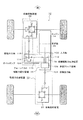
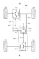
図1は、本発明による四輪駆動車用駆動力伝達装置の実施形態を示した説明図であり、二輪駆動モードでは後輪を駆動する方式の車両に適用した場合である。図1において、本実施形態の駆動力伝達装置10は四輪駆動車12に設けられ、駆動力配分装置18、後輪差動装置20及び前輪差動装置22を備える。後輪差動装置20及び前輪差動装置22は各々後輪プロペラシャフト24及び前輪プロペラシャフト26を介して駆動力配分装置18に連結されている。
FIG. 1 is an explanatory diagram showing an embodiment of a driving force transmission device for a four-wheel drive vehicle according to the present invention, which is applied to a vehicle in which a rear wheel is driven in a two-wheel drive mode. In FIG. 1, the driving force transmission device 10 of this embodiment is provided in a four-
エンジン14からの駆動力は変速機16で変速され、駆動力配分装置18の入力軸102に入力し、二輪駆動モードで、入力軸102に同軸に設けられた多板クラッチ機構106が開放されている場合、駆動力はそのまま後輪出力軸104に出力され、自在継手28、後輪プロペラシャフト24、自在継手30を介し、後輪差動装置20のドライブピニオン36に伝達される。
The driving force from the
ドライブピニオン36は、リングギア38、ピニオン40、42、サイドギア44、46を介して左後輪駆動軸48及び右後輪駆動軸50を駆動し、左後輪駆動軸48及び右後輪駆動軸50は各々左後輪52及び右後輪54を回転させ駆動力を路面に伝達する。コーナリング時や路面状態の変化等により左後輪52と右後輪54に回転速度差が生じても、後輪差動装置20は回転速度差を吸収し、左後輪52及び右後輪54に等しいトルクを与え回転させることができる。
The
ドライバーが二輪駆動モードから四輪駆動オートモードに切り替えると、ECUはまず多板クラッチ機構106を締結し、続いて断接機構76の連結を接続することで、多板クラッチ機構106からの駆動力が左前輪72及び右前輪74に伝達可能となる。
When the driver switches from the two-wheel drive mode to the four-wheel drive auto mode, the ECU first fastens the multi-plate
多板クラッチ機構106が締結されると、多板クラッチ機構106に同軸に連結されたスプロケット112がチェーンベルト116を介しスプロケット114を回転させることで駆動力は前輪出力軸118にも伝達される。
When the multi-plate
前輪出力軸118から出力された駆動力は自在継手32、前輪プロペラシャフト26、自在継手34を介し、前輪差動装置22のドライブピニオン56に伝達され、ドライブピニオン56は、リングギア58、ピニオン60、62、サイドギア64、66を介して左前輪駆動軸68及び右前輪駆動軸70を駆動し、左前輪駆動軸68及び右前輪駆動軸70は各々左前輪72及び右前輪74を回転させ駆動力を路面に伝達する。
The driving force output from the front wheel output shaft 118 is transmitted to the
断接機構76は四輪駆動時にはサイドギア64と左前輪駆動軸68を連結しており、サイドギア64の回転はそのまま左前輪駆動軸68に伝達される。コーナリング時や路面状態の変化等により左前輪72と右前輪74に回転速度差が生じても、前輪差動装置22は回転速度差を吸収し、左前輪72及び右前輪74に等しいトルクを与え回転させることができる。
The connection /
多板クラッチ機構106の締結力はサーボモータにより連続的に制御され、必要に応じて前輪出力軸118へ伝達する駆動力を増減させることで、前後輪の駆動力配分を制御する。
The fastening force of the multi-plate
四輪駆動オートモードから二輪駆動モードに切り替えると、ECUはまず多板クラッチ機構106を開放し、続いて断接機構76の連結を切断する。この場合、ECUは先に断接機構76の連結を切断した後に多板クラッチ機構106を開放してもよい。
When switching from the four-wheel drive auto mode to the two-wheel drive mode, the ECU first opens the multi-plate
断接機構76はサイドギア64と左前輪駆動軸68との連結を絶ち、左前輪72及び右前輪74が路面から受ける回転力がリングギア58を回転させることを防止する。これにより、二輪駆動時に燃費低下を招く要因である、前輪を駆動しない二輪駆動時にもリングギア58からスプロケット112までの前輪駆動力伝達区間78が回転してしまう問題を解消できる。
The connection /
また、ドライバーが切り替えスイッチを操作しなくても、車両状態を検出してECUの判断により、四輪駆動の必要がない時には自動的に二輪駆動モードに切り替え、逆に四輪駆動が必要な時には四輪駆動モードに切り替えるようにしてもよい。 Even if the driver does not operate the changeover switch, it automatically switches to the two-wheel drive mode when the vehicle state is detected and the ECU judges that the four-wheel drive is not necessary, and conversely when the four-wheel drive is necessary. You may make it switch to four-wheel drive mode.
図1において、仮に、二輪駆動モード時にサイドギア64と左前輪駆動軸68が連結されているとすると、例えばサイドギア64及び66が同方向に同速度で回転する場合、ピニオン60及びピニオン62は回転(自転)せずにリングギア58が回転する。サイドギア64及び66に回転速度差があったとしても同方向の回転であれば回転速度は変化するがリングギア58は回転し、リングギア58が回転することで連結しているドライブピニオン56、自在継手34、前輪プロペラシャフト26、自在継手32、前輪出力軸118、スプロケット114、チェーンベルト116、スプロケット112が回転してしまう。
In FIG. 1, if the
この、リングギア58からスプロケット112までの前輪駆動力伝達区間78は二輪駆動時には回転する必要のない部位であるにも関わらず、この部分の回転がオイルの粘性抵抗や軸受部の摩擦損失等を引き起こす。すなわち、左後輪52及び右後輪54から路面に伝わった駆動力が左前輪72及び右前輪74を回転させることで、二輪駆動時には回転する必要のない前輪駆動力伝達区間78を回転させ、駆動力の損失となり燃費低下を招いてしまう。
Although the front wheel driving force transmission section 78 from the
そこで、本発明にあっては、二輪駆動モードでは断接機構76によりサイドギア64と左前輪駆動軸68の連結を絶つと共に、多板クラッチ機構106の引き摺りトルクを前輪駆動力伝達区間78のフリクショントルクよりも小さくすることで、前輪駆動力伝達区間78の回転を防止している。
Therefore, in the present invention, in the two-wheel drive mode, the connection and
サイドギア64と左前輪駆動軸68の連結が絶たれると、左前輪72の回転はサイドギア64に伝わらず、そのため、右前輪74によるサイドギア66の回転はピニオン60及びピニオン62を介してサイドギア64を反対方向に回転させることが可能で、このピニオン60、ピニオン62、サイドギア64の回転抵抗よりも、リングギア58に繋がるドライブピニオン56からスプロケット112までの回転抵抗の方が大きいため、リングギア58は回転しない。
When the connection between the
リングギア58が回転しないということは、前輪駆動力伝達区間78が回転しないことであり、この場合の駆動力の損失はピニオン60、ピニオン62、サイドギア64が回転する部分だけとなり、断接機構76がなく前輪駆動力伝達区間78が回転してしまう場合と比べて燃費向上が可能である。
The fact that the
なお、本実施形態において、断接機構76は前輪差動装置22内のサイドギア64と左前輪駆動軸68の中間に設置されているが、サイドギア64と左前輪駆動軸68を断続する位置、あるいはサイドギア66と右前輪駆動軸70を断続する位置、又はその両方の位置であれば前輪差動装置22内に設置するか外に設置するかを問わない。更に、ピニオン60、62、サイドギア64、66で構成するユニットをリングギア58と分離し、その連結を断続する方式等の他の機構でも構わない。
In the present embodiment, the connection /
図2は、図1の前輪差動装置22の実施形態を示した断面図であり、断接機構76を備える。図2において、前輪差動装置22はデフケース80の外周部に固定されたリングギア58、デフケース80に固定されたピニオン軸82に回転自在に軸支されたピニオン60及びピニオン62、サイドギア軸84に回転不可に軸支されデフケース80内でピニオン60及びピニオン62と噛み合うサイドギア64、右前輪駆動軸70に回転不可に軸支されデフケース80内ピニオン60及びピニオン62と噛み合うサイドギア66を備える。
FIG. 2 is a cross-sectional view showing an embodiment of the front wheel
更に、端部68bがサイドギア軸84に回転方向に拘束されずに勘合している左前輪駆動軸68、左前輪駆動軸68の歯部68a及びサイドギア軸84の歯部84aとスプライン結合し、左前輪駆動軸68とサイドギア軸84を連結する位置と連結を解除する位置でスライド可能なスリーブ86、スリーブ86の溝部86aに摺動自在に係合する先端部88aによりスリーブ86をスライドさせるフォーク88、フォーク88に固定され図示しないアクチュエータにより軸方向に駆動されるシフト軸90を備え、四輪駆動時にリングギア58と噛み合うドライブピニオン56からの駆動力を左前輪72及び右前輪74に伝達する。
Further, the
図2(A)は、二輪駆動時の断接機構76が非連結状態で、スリーブ86はサイドギア軸84の歯部84aと噛み合っていない。右前輪駆動軸70の回転はサイドギア66、ピニオン60及びピニオン62を介してサイドギア64に伝わり、リングギア58が回転しないことからサイドギア軸84を右前輪駆動軸70とは反対方向に回転させる。
In FIG. 2A, the connecting /
図2(B)は、四輪駆動時にフォーク88がL方向に移動し断接機構76が連結された状態で、スリーブ86はサイドギア軸84の歯部84aと噛み合っている。ドライブピニオン56によりリングギア58が回転し、左前輪駆動軸68と右前輪駆動軸70を同方向に回転させる。二輪駆動に戻る際にはフォーク88がU方向に移動し断接機構76は非連結状態に戻る。
FIG. 2B shows the
二輪駆動モード時に燃費低下を招く他の要因として、多板クラッチ機構106に備わる複数のクラッチ板の駆動側(後輪側)と従動側(前輪側)の回転速度差により発生するオイルの粘性抵抗やクラッチ板同士の接触による摩擦損失、いわゆる引き摺りトルクが前輪駆動力伝達区間78のフリクショントルクより大きいために、前輪駆動力伝達区間78が回転してしまう問題がある。
Another factor that causes a reduction in fuel consumption in the two-wheel drive mode is the oil viscosity resistance generated by the difference in rotational speed between the drive side (rear wheel side) and the driven side (front wheel side) of the plurality of clutch plates provided in the multi-plate
図3は、図1の駆動力配分装置18の実施形態を示した断面図である。図3において、駆動力配分装置18はケース100を有し、ケース100の左側にエンジン14からの駆動力を変速機16を介して入力する入力軸102が設けられ、入力軸102は、ケース100の右側に配置された後輪出力軸104に直結されている。
FIG. 3 is a cross-sectional view showing an embodiment of the driving force distribution device 18 of FIG. In FIG. 3, the driving force distribution device 18 has a case 100, and an
入力軸102と同軸に多板クラッチ機構106とボールカム機構122が設けられ、多板クラッチ機構106はクラッチハブ108を入力軸102に固定し、クラッチドラム110を入力軸102に対し回転自在に設けたスプロケット112に連結している。
A multi-plate
入力軸102と平行に、後輪出力軸104と反対側に駆動力を出力する前輪出力軸118がケース100の左下側に設けられており、前輪出力軸118にはスプロケット114が連結され、多板クラッチ機構106側のスプロケット112との間にチェーンベルト116を掛けて連結している。
A front wheel output shaft 118 that outputs driving force to the opposite side of the rear wheel output shaft 104 is provided on the lower left side of the case 100 in parallel with the
ボールカム機構122の後輪出力軸104側にはオイルポンプ184が配置され、入力軸102から動力を得て入力軸102に設けられた油路186にオイルを供給する。
An
このような駆動力配分装置18において、二輪駆動時には、多板クラッチ機構106のクラッチハブ108とクラッチドラム110の間が開放され、入力軸102の駆動力は後輪出力軸104に直接伝達される。
In such a driving force distribution device 18, during the two-wheel drive, the
四輪駆動時にあっては、多板クラッチ機構106が締結され、入力軸102からの駆動力を多板クラッチ機構106、スプロケット112、チェーンベルト116、スプロケット114を介して前輪出力軸118にも伝達する。
During four-wheel drive, the multi-plate
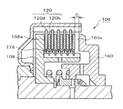
図4は、図3の多板クラッチ機構106及びボールカム機構122を示した断面図である。図4において、多板クラッチ機構106に対しては、クラッチハブ108とクラッチドラム110の間に設けた複数のクラッチ板120の締結力を制御するボールカム機構122が設けられる。クラッチ板120は、クラッチ板同士の間隔を保持するスペーサ178を備える。
4 is a cross-sectional view showing the multi-plate
ボールカム機構122は、入力軸102と同軸に相対回転自在に設けられた一対の固定カムプレート124と回転カムプレート126の対向するカム面のボールカム溝128にボール140を挟んで保持している。更に、固定カムプレート124と回転カムプレート126の間には位置決め用の突起部138を有するリテーナ136を備える。
The
図5は、図3のボールカム機構122を後輪出力軸104の方向から見た説明図である。図5において、固定カムプレート124は、アーム部142を延在してU字形の先端を保持部152aの外側に嵌め入れて回転を停止させている。回転カムプレート126は、円周方向に複数のボールカム溝128を有し、アーム部144を延在して先端に形成した扇型ギア146が駆動ギア148に噛み合っている。
FIG. 5 is an explanatory view of the
再び、図3及び4を参照するに、サーボモータ150は減速機152を介して駆動ギア148を回転させる。固定カムプレート124の右側にはスラスト軸受154を介して固定プレート158が配置され、回転カムプレート126の左側にはスラスト軸受156を介して押圧部材160が配置される。押圧部材160は、クラッチハブ108との間に備わる復帰ばね162により多板クラッチ機構106の開放方向に付勢されている。
Referring again to FIGS. 3 and 4, the
ボールカム機構122は、駆動ギア148により回転カムプレート126が固定カムプレート124に対し所定方向に回転駆動されると、対向する面の傾斜溝であるボールカム溝128に挟まれているボール140による押圧を受けて押圧部材160及び復帰ばね162を軸方向に押し、押圧部材160が多板クラッチ機構106のクラッチ板120を押すことで、駆動ギア148の回転量に応じて伝達トルクを増加させ、最大押付け位置で直結状態となる。
When the rotating
入力軸102、クラッチハブ108及び押圧部材160に囲まれる部位には、油路186から多板クラッチ機構106の複数のクラッチ板120へのオイルの供給を制御する油孔開閉部164が配置される。油孔開閉部164は、油孔168、ラチェット爪170を有する油孔位置調整部材166、皿ばね172、入力軸102に設けられたラック174、押圧部材160に設けられ油孔168を開閉する弁部176で構成される。
An oil hole opening /
図6は、図3の多板クラッチ機構106の油孔開閉部164の動作を示す説明図である。図6(A)は、二輪駆動時の多板クラッチ機構106が開放された状態で、押圧部材160はクラッチ板120から最も離れた待機位置に在る。油孔位置調整部材166は皿ばね172により右方に付勢されているがラチェット爪170とラック174で規制されている。
FIG. 6 is an explanatory view showing the operation of the oil hole opening /
この状態では、クラッチ板120の内でクラッチドラム110に係合した方は回転しないが、クラッチハブ108に係合した方が入力軸102の回転と共に回転する。しかし、押圧部材160がこの位置では弁部176が油孔168を閉じているため、油路186からのオイルはクラッチ板120には供給されず、オイルによる粘性抵抗を軽減することでクラッチドラム110側の引き摺りを防止できる。
In this state, one of the
なお、本実施形態にあっては、図6(A)の多板クラッチ機構106が開放された状態で、弁部176が油孔168を完全に閉じているが、この時点で弁部176が油孔168を完全に閉じることなく、若干のオイルをクラッチ板120に供給するように構成してもよく、その量はクラッチ板120の潤滑や冷却を考慮して任意に設定できる。
In the present embodiment, the
図6(B)は、二輪駆動から四輪駆動へ切り替わる途中の多板クラッチ機構106の締結初期状態で、ボールカム機構122に押され左方に移動した押圧部材160はクラッチ板120に接触を開始した位置に在る。この時点からクラッチ板120同士も徐々に接触を始め、その摩擦トルクにより多板クラッチ機構106は駆動力を前輪側に伝達し始める。この位置では弁部176が油孔168を開いているため、矢印で示すように油路186からオイルがクラッチ板120に供給され、クラッチ板同士の焼き付を防止する。
FIG. 6B shows an initial engagement state of the multi-plate
図6(C)は、四輪駆動に切り替わり多板クラッチ機構106が完全に締結された状態で、押圧部材160はクラッチ板120同士の隙間が全く無い最大押付け位置に在る。油孔位置調整部材166は、突起166aが弁部176に押され、押圧部材160の最大押付け位置でラチェット爪170がラック174に係合し保持される。
FIG. 6C shows a state where the multi-plate
図7は、図6の油孔開閉部164の油孔位置調整部材166の動作を示す説明図である。図7(A)はクラッチ板120が磨耗をしていない状態、あるいは磨耗の初期状態での油孔開閉部164を示し、図7(B)はクラッチ板120の磨耗が進行した状態での油孔開閉部164を示している。
FIG. 7 is an explanatory view showing the operation of the oil hole
図7(A)から図7(B)にクラッチ板120の磨耗が進むと、押圧部材160の最大押付け位置が全てのクラッチ板120の減少した板厚の合計に略等しい距離分クラッチストロークが深くなる方向、図7において距離W左方に移動する。押圧部材160の最大押付け位置の移動に伴い、油孔位置調整部材166の突起166aが弁部176に押し込まれる位置も左方に変化し、その押し込まれた位置でラチェット爪170がラック174に係止し、油孔位置調整部材166が保持される。
When the
油孔位置調整部材166がクラッチ板120の磨耗に追従することで、油孔168の開き始めのタイミングはクラッチ板120の磨耗度に影響されず、クラッチ板120同士の間隔に対し略一定となり、クラッチ板120の潤滑、冷却や引き摺り等に影響するオイル供給量の安定化が図れる。
When the oil hole
図8は、図3の多板クラッチ機構106のスペーサ178の設置状態を示す説明図である。図8は、二輪駆動時の多板クラッチ機構106が開放された状態で、押圧部材160はクラッチ板120から最も離れた待機位置に在る。
FIG. 8 is an explanatory view showing an installation state of the
多板クラッチ機構106は軸方向に移動可能な複数のクラッチ板120を備え、クラッチ板120は、クラッチハブ108の外周に内側クラッチ板120hがスプライン嵌合されて、クラッチドラム110の内周には外側クラッチ板120dがスプライン嵌合されおり、内側クラッチ板120hと外側クラッチ板120dは1枚置きに配置される。外側クラッチ板120dの内周部には板材を成形した板ばねであるスペーサ178を備え、隣接する両側の内側クラッチ板120hと引き摺りを起さない摩擦面同士の隙間を確保する。
The multi-plate
クラッチ板120はクラッチハブ108の受圧面108aと押圧部材160の押圧面160aの間で軸方向に移動可能であり、押圧面160aとの隙間Eがあるが、スペーサ178がないとクラッチ板120同士は、オイルによって粘着し分離せず、引き摺りを起す。スペーサ178が摩擦面同士の隙間を確保することで、引き摺りによる駆動力の損失を防止し燃費を向上させることが可能となる。
The
なお、押圧部材160がクラッチ板120から最も離れた待機位置に在る場合の隙間Eの値は、クラッチ120同士の隙間の状態により一定とは限らない。
Note that the value of the gap E when the
スペーサ178は内側クラッチ板120hの外周部に設置することも可能であるが、トルク損失の小さな内側の方が好ましい。すなわち、スペーサ178が設置されたクラッチ板120に隣接するクラッチ板120と、スペーサ178との摺動による摩擦抵抗が同じであれば内側に設置した方が摩擦トルクは少なく、摩擦トルクは駆動力の損失となるためである。また、スペーサ178のばね荷重は隣接するクラッチ板120hとの間隔を維持できる範囲で小さい方が好ましい。
The
図9は、図8のスペーサを示す斜視図である。図9において、スペーサ178は板材を成形した板ばねであり、外側クラッチ板120dの内周部に設けた板厚方向の凹部120cに挿入する挟持部180と、挟持部180から隣接するクラッチ板120の両表面の外径方向に延び、クラッチ板120の軸方向に変形可能な弾性片182を備る。
FIG. 9 is a perspective view showing the spacer of FIG. In FIG. 9, a
スペーサ178を矢印で示す方向に凹部120cに挿入し固定するために、挟持部180の間隔は凹部120cの厚みより狭く設定される。
In order to insert and fix the
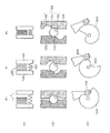
図10は、図8のスペーサ178を示す断面図である。図10(A)は、四輪駆動時の多板クラッチ機構106が締結された状態で、スペーサ178が設置された外側クラッチ板120dと隣接する内側クラッチ板120hの各々の摩擦面が密着し回転している。図10(B)は、二輪駆動時の多板クラッチ機構106が開放された状態で、スペーサ178が設置された外側クラッチ板120dと隣接する内側クラッチ板120hの各々の摩擦面がスペーサ178により引き摺りを起さない隙間に隔離されている。
FIG. 10 is a cross-sectional view showing the
図10(B)において、内側クラッチ板120hは回転し、外側クラッチ板120dは回転しないため、スペーサ178の弾性片182の先端が隣接する内側クラッチ板120hと摺動する。そのため、弾性片182の先端は摩擦面ではない部位と接触するのが好ましい。
In FIG. 10B, since the inner
図11は、図3の多板クラッチ機構106のスペーサ178の他の実施形態を示す断面図である。図11おいて、スペーサ178は板材を成形した板ばねであり、外側クラッチ板120dの内周部に設けた板厚方向の凹部120cに挿入する挟持部180と、挟持部180から隣接する内側クラッチ板120hの両表面の内径方向に延び、内側クラッチ板120hの軸方向に変形可能な弾性片182を備える。
FIG. 11 is a cross-sectional view showing another embodiment of the
図11(A)は、多板クラッチ機構106が締結された状態で、スペーサ178が設置された外側クラッチ板120dと隣接する内側クラッチ板120hの各々の摩擦面が密着している。図11(B)は、多板クラッチ機構106が開放された状態で、スペーサ178が設置された外側クラッチ板120dと隣接する内側クラッチ板120hの各々の摩擦面がスペーサ178により引き摺りを起さない隙間に隔離されている。
In FIG. 11A, the friction surfaces of the inner
図11(A)と(B)の中間の位置においては、内側クラッチ板120hと外側クラッチ板120dは共に回転するが、回転速度差があるため弾性片182の先端が隣接する内側クラッチ板120hと摺動する。しかし、弾性片182の先端は外側クラッチ板120dの回転による遠心力で、矢印で示すように閉じる方向に力を受けることで摩擦抵抗を減らすことができる。
11A and 11B, the inner
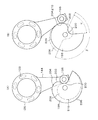
図12は、図3のボールカム機構122のボールカム溝128とリテーナ136を示す説明図である。図12において、一対の固定カムプレート124と回転カムプレート126の相対するカム面のボールカム溝128にボール140を挟んで保持している。ボールカム溝128は、乗り越え部134を境界にしてカム形状が異なる初期領域130と傾斜領域132を有する。
FIG. 12 is an explanatory view showing the
また、固定カムプレート124と回転カムプレート126の間には各ボール140の相対位置を保持するリテーナ136を備え、リテーナ136はボールカム溝128に対するボール140の初期位置を規制する位置決め用の突起部138を設ける。突起部138は回転カムプレート126の外周部に形成したガイド部127に係合している。
Further, a
図12(A)は、二輪駆動時の多板クラッチ機構106が開放され、押圧部160が待機位置に在る状態で、ボール140は固定カムプレート124と回転カムプレート126の両ボールカム溝128の初期領域130に位置する。
FIG. 12A shows the
図12(B)は、二輪駆動から四輪駆動へ移行する際の、多板クラッチ機構106の締結初期の押圧部材160がクラッチ板120に接触を開始した位置に在る状態で、ボール140はボールカム溝128の乗り越え部134から傾斜部132に移行した位置にある。
FIG. 12B shows a state in which the
図12(C)は、四輪駆動へ切り替わり、多板クラッチ機構106が締結されて押圧部材160がクラッチ板120同士を押圧する位置に在る状態で、ボール140はボールカム溝128の傾斜部132に位置する。
FIG. 12C shows a state in which the four-wheel drive is switched to the state where the multi-plate
荷重を分散するために円周上にボール140を複数配置した場合、ボールカム機構122の作動時にボールカム溝128とボール140との滑りにより各ボールの相対的な位置ずれが生じることがあり、その場合、複数のボールカム溝128を均等に押すことができなくなり、多板クラッチ機構106への偏荷重やボールカム溝128の表面の耐久性が著しく低下する。
When a plurality of
リテーナ136を備えることで、各ボール140の相対位置が保持され、また、図12(C)から図12(A)の初期位置に戻る毎に、位置決め用の突起部138により各ボール140のボールカム溝128に対する初期位置が補正される。
By providing the
図13は、図1の駆動力配分装置18の他の実施形態を示した断面図であり、図3及び4に示す実施形態に対し、ボールカム機構122が異なる点を除けば同じ構成である。図13において、サーボモータ150は減速機152を介して周縁カム198を回転させる。
FIG. 13 is a cross-sectional view showing another embodiment of the driving force distribution device 18 of FIG. 1 and has the same configuration as the embodiment shown in FIGS. 3 and 4 except that the
回転カムプレート126は、アーム部144を延在して先端に、回転可能なローラから成るカムフォロア196を設けており、カムフォロア196は周縁カム198の外周部に接している。
The rotating
ボールカム機構122は、周縁カム198により回転カムプレート126が固定カムプレート124に対し所定方向に回転駆動されると、対向する面の傾斜溝であるボールカム溝128に挟まれているボール140による押圧を受けて押圧部材160及び復帰ばね162を軸方向に押し、押圧部材160が多板クラッチ機構106のクラッチ板120を押すことで、駆動ギア148の回転量に応じて伝達トルクを増加させ、最大押付け位置で直結状態となる。
When the rotating
図14は、図13のボールカム機構122を入力軸102の方向から見た説明図である。図14において、回転カムプレート126は、円周方向に複数のボールカム溝128を有する。この実施例におけるボールカム溝128は、図3の実施例において図12に示すような乗り越え部134は存在せず、傾斜領域132は初期領域130から段差なく接する形状をしている。
FIG. 14 is an explanatory view of the
回転カムプレート126から延在するアーム部144の先端に設けられたカムフォロア196の外周部は、周縁カム198のカム面に接している。周縁カム198のカム面は、初期領域200、非線形領域202及び線形領域206で構成され、時計方向に回転することでカムフォロア196を介して回転カムプレート126を回転駆動し、多板クラッチ機構106を押圧する。
The outer peripheral portion of the
図14(A)は、二輪駆動時の多板クラッチ機構106が開放され、押圧部160が待機位置に在る状態で、カムフォロア196は周縁カム198のカム面の初期領域200に位置する。
14A, the
図14(B)は、二輪駆動から四輪駆動へ移行する際の、多板クラッチ機構106の締結初期の押圧部材160がクラッチ板120に接触を開始した位置に在る状態で、カムフォロア196は周縁カム198のカム面の非線形領域202から線形領域206に移行する位置に在り、この点が押圧開始位置204となる。
FIG. 14B shows the
周縁カム198の押圧開始位置204は、非線形領域202から線形領域206に移行する位置の近傍であれば非線形領域202に在っても線形領域206に在っても構わないが、非線形領域202から線形領域206に移行する点が望ましい。
The
ここで、従来例として非線形領域のない線形カム208の形状を示して周縁カム198との比較をすると、線形カム208においては押圧部材160がクラッチ板120を押圧始める押圧開始位置210までに角度βを要するが、非線形領域202の存在する周縁カム198においては角度βよりはるかに小さな角度αで押圧開始位置204に達する。
Here, as a conventional example, the shape of the
図15及び16は、図12及び14に示すボールカム機構122の動作説明図である。図15は、多板クラッチ機構106の押圧部材160に作用するカム荷重188と、押圧部材160のストローク190の関係、及びばね荷重192を模式的に示したグラフで、横軸は回転カムプレート126のカム角度(θ)、縦軸はカム荷重(F)とストローク(S)を表している。
15 and 16 are explanatory diagrams of the operation of the
押圧部材160のストローク190は、カム角度θ0からθ1までが非線形領域で、カム角度θ1以降θmaxまでが線形領域であり、クラッチトルク(T)の軸は、カム角度θ1のバネ荷重192を始点(T0)とし、バネ荷重192の傾きに直角である。
The
図16(A)は、図15に示すカム角度θに対応した、押圧部材160、クラッチドラム108、クラッチ板120及び復帰ばね162の状態を表し、各々、多板クラッチ機構106の待機状態θ0、締結開始θ1、締結状態θnである。
16A shows the states of the
図16(B)は、図12に示す固定カムプレート124、回転カムプレート126及びボール140のカム角度θに対応した位置関係を表し、左から各々、カム角度θ0のボール140がボールカム溝128の初期領域130に在る場合、カム角度θ1のボール140がボールカム溝128の乗り越え部134を乗り越え終わった位置に在る場合、カム角度θnのボール140がボールカム溝128の傾斜領域132に在る場合である。
FIG. 16B shows the positional relationship corresponding to the cam angle θ of the fixed
図16(C)は、図14に示す周縁カム198と回転カムプレート126のアーム部144の先端に位置するカムフォロア196のカム角度θに対応した位置関係を表し、左から各々、カム角度θ0のカムフォロア196が周縁カム198の初期領域200に在る場合、カム角度θ1のカムフォロア196が周縁カム198の押圧開始位置204に在る場合、カム角度θnのカムフォロア196が周縁カム198の線形領域206に在る場合である。
FIG. 16C shows the positional relationship corresponding to the cam angle θ of the
多板クラッチ機構106において、押圧部160の移動は、待機位置からクラッチ板120に接触を開始する位置までは、復帰ばね162を押し込むだけの小さな荷重でよいが、二輪駆動から四輪駆動への移行応答性を良くするために大な速度が必要になる。特に、二輪駆動時の引き摺りを防止するためにクラッチ板120同士の間隔を広げ、多板クラッチ機構106のエンドプレイを大きく取った場合はこの区間の移動速度が重要になる。
In the multi-plate
カム角度θ0の待機状態では、押圧部材160とクラッチ板120とに距離eのエンドプレイがあり、図16(B)の場合、ボール140がカム角度θ0からカム角度θ1のボールカム溝128の乗り越え部134を乗り越える非線形領域でこの距離eをすばやく詰める。
In the standby state of the cam angle θ0, there is an end play of the distance e between the
図16(C)の場合は、カムフォロア196がカム角度θ0からカム角度θ1で非線形領域202を経て押圧開始位置204に移動することでこの距離eをすばやく詰める。このカム角度θ0からカム角度θ1の区間でのカム荷重(F)は復帰ばね162のばね荷重192のみであるため、小さなカム角度θ1で大きなストロークS1を得ることが可能である。
In the case of FIG. 16C, the
その後、押圧部材160がクラッチ板120に接触し押圧を開始すると、クラッチ板120にクラッチトルク(T)が発生し、カム荷重(F)は急激に増加する。カム角度θ1以降は、ボール140はボールカム溝128の傾斜領域132に在り、カム角度θnのストロークSnにおいて、荷重Fnからバネ荷重192を引いた値がクラッチトルクTnに相当する。
Thereafter, when the
図17は、本発明による四輪駆動車用駆動力伝達装置の他の実施形態を示した説明図であり、図1に示す実施形態に対しオイルポンプ194を除けば同じ構成である。図17において、スプロケット114にはオイルポンプ194が連結されており、多板クラッチ機構106が締結されスプロケット114が回転するとオイルポンプ194はオイルを図示しない油圧回路を経由して多板クラッチ機構106に供給し、多板クラッチ機構106に備わる複数のクラッチ板の摩擦熱による焼き付きを防止する。
FIG. 17 is an explanatory view showing another embodiment of the driving force transmission device for a four-wheel drive vehicle according to the present invention, and is the same as the embodiment shown in FIG. 1 except for the oil pump 194. In FIG. 17, an oil pump 194 is connected to the
なお、本実施形態において、オイルポンプ194はスプロケット114に連結され動力を得ているが、二輪駆動時に駆動力が伝達されない部位、例えばスプロケット112やチェーンベルト116から動力を得るようにしても構わない。
In this embodiment, the oil pump 194 is connected to the
図18は、図17の駆動力配分装置18の実施形態を示した断面図であり、図3に示す実施形態に対し入力軸102が駆動するオイルポンプ184がなく、代わりにスプロケット114が駆動するオイルポンプ194があること、及び図4に詳細を示す油孔開閉部164が存在しないことを除けば同じ構成である。
FIG. 18 is a cross-sectional view showing an embodiment of the driving force distribution device 18 of FIG. 17, and there is no
図18において、スプロケット114の前輪出力軸118とは反対側にはオイルポンプ194が配置され、スプロケット114の軸から動力を得て、図示しない油圧回路を経由して入力軸102に設けられた油路186にオイルを供給する。
In FIG. 18, an oil pump 194 is disposed on the opposite side of the
このような構成において、二輪駆動時の多板クラッチ機構106が開放され、押圧部材160はクラッチ板120から最も離れた待機位置に在る状態では、クラッチ板120の内でクラッチドラム110に係合した方は回転しないが、クラッチハブ108に係合した方が入力軸102の回転と共に回転する。
In such a configuration, the multi-plate
しかし、クラッチドラム110が回転しないことから、スプロケット112、チェーンベルト116を介したスプロケット114が回転せず、よってオイルポンプ194は油路186にオイルを吐出しないため、油路186からのオイルはクラッチ板120には供給されず、オイルによる粘性抵抗を軽減することでクラッチドラム110側の引き摺りを防止できる。
However, since the
二輪駆動から四輪駆動へ切り替わり、ボールカム機構122に押され左方に移動した押圧部材160がクラッチ板120を押圧し、クラッチ板120同士が接触した状態ではクラッチドラム110が回転するため、スプロケット112、チェーンベルト116を介してスプロケット114が回転する。従って、スプロケット114に駆動されるオイルポンプ194は油路186にオイルを吐出することで、油路186からオイルがクラッチ板120に供給され、クラッチ板同士の焼き付を防止する。
Switching from two-wheel drive to four-wheel drive, and the
図19は、図17の駆動力配分装置18の他の実施形態を示した断面図であり、図18に示す実施形態に対しスプロケット114が駆動するオイルポンプ194の代わりにスプロケット112が駆動するオイルポンプ212があることを除けば同じ構成である。
FIG. 19 is a cross-sectional view showing another embodiment of the driving force distribution device 18 of FIG. 17, and oil driven by the
図19において、スプロケット112の入力軸102側にはオイルポンプ212が配置され、スプロケット112の軸から動力を得て、入力軸102に設けられた油路186にオイルを供給する。このように構成しても図18に示すものと同様な効果が得られる。
In FIG. 19, an oil pump 212 is disposed on the
また、本発明は上記の実施形態に限定されず、その目的と利点を損なうことのない適宜の変形を含み、更に上記の実施形態に示した数値による限定は受けない。
The present invention is not limited to the above-described embodiment, includes appropriate modifications without impairing the object and advantages thereof, and is not limited by the numerical values shown in the above-described embodiment.
10:駆動力伝達装置
12:四輪駆動車
14:エンジン
16:変速機
18:駆動力配分装置
20:後輪差動装置
22:前輪差動装置
24:後輪プロペラシャフト
26:前輪プロペラシャフト
28、30、32、34:自在継手
36:ドライブピニオン
38:リングギア
40、42:ピニオン
44、46:サイドギア
48:左後輪駆動軸
50:右後輪駆動軸
52:左後輪
54:右後輪
56:ドライブピニオン
58:リングギア
60、62:ピニオン
64、66:サイドギア
68:左前輪駆動軸
70:右前輪駆動軸
72:左前輪
74:右前輪
76:断接機構
78:前輪駆動力伝達区間
80:デフケース
82:ピニオン軸
84:サイドギア軸
86:スリーブ
88:フォーク
90:シフト軸
100:ケース
102:入力軸
104:後輪出力軸
106:多板クラッチ機構
108:クラッチハブ
110:クラッチドラム
112、114:スプロケット
116:チェーンベルト
118:前輪出力軸
120:クラッチ板
122:ボールカム機構
124:固定カムプレート
126:回転カムプレート
128:ボールカム溝
130:初期領域
132:傾斜領域
134:乗り越え部
136:リテーナ
138:突起部
140:ボール
142、144:アーム部
146:扇型ギア
148:駆動ギア
150:サーボモータ
152:減速機
154、156:スラスト軸受
158:固定プレート
160:押圧部材
162:復帰ばね
164:油孔開閉部
166:油孔位置調整部材
168:油孔
170:ラチェット爪
172:皿ばね
174:ラック
176:弁部
178:スペーサ
180:挟持部
182:弾性片
184、194、212:オイルポンプ
186:油路
188:カム荷重
190:ストローク
192:ばね荷重
196:カムフォロア
198:周縁カム
200:初期領域
202:非線形領域
204、210:押圧開始位置
206:線形領域
208:線形カム
300:駆動力伝達装置
302:四輪駆動車
304:エンジン
306:変速機
308:駆動力配分装置
310:多板クラッチ機構
312:チェーンベルト機構
314:後輪プロペラシャフト
316:前輪プロペラシャフト
318:後輪差動装置
320:左後輪
322:右後輪
324:前輪差動装置
326:左前輪
328:右前輪
330:前輪駆動力伝達区間
332:リングばね
10: Driving force transmission device 12: Four-wheel drive vehicle 14: Engine 16: Transmission 18: Driving force distribution device 20: Rear wheel differential device 22: Front wheel differential device 24: Rear wheel propeller shaft 26: Front wheel propeller shaft 28 , 30, 32, 34: universal joint 36: drive pinion 38: ring gear 40, 42: pinion 44, 46: side gear 48: left rear wheel drive shaft 50: right rear wheel drive shaft 52: left rear wheel 54: right rear Wheel 56: Drive pinion 58: Ring gear 60, 62: Pinion 64, 66: Side gear 68: Left front wheel drive shaft 70: Right front wheel drive shaft 72: Left front wheel 74: Right front wheel 76: Disconnection mechanism 78: Front wheel drive force transmission Section 80: Differential case 82: Pinion shaft 84: Side gear shaft 86: Sleeve 88: Fork 90: Shift shaft 100: Case 102: Input shaft 104: Rear wheel output shaft 106: Plate clutch mechanism 108: Clutch hub 110: Clutch drum 112, 114: Sprocket 116: Chain belt 118: Front wheel output shaft 120: Clutch plate 122: Ball cam mechanism 124: Fixed cam plate 126: Rotating cam plate 128: Ball cam groove 130: Initial Area 132: Inclined area 134: Passing part 136: Retainer 138: Protrusion part 140: Ball 142, 144: Arm part 146: Fan gear 148: Drive gear 150: Servo motor 152: Reducer 154, 156: Thrust bearing 158: Fixed plate 160: Pressing member 162: Return spring 164: Oil hole opening / closing part 166: Oil hole position adjusting member 168: Oil hole 170: Ratchet claw 172: Belleville spring 174: Rack 176: Valve part 178: Spacer 180: Clamping part 182 : Elastic pieces 184, 1 4, 212: Oil pump 186: Oil passage 188: Cam load 190: Stroke 192: Spring load 196: Cam follower 198: Peripheral cam 200: Initial region 202: Non-linear region 204, 210: Pressing start position 206: Linear region 208: Linear Cam 300: Driving force transmission device 302: Four-wheel drive vehicle 304: Engine 306: Transmission 308: Driving force distribution device 310: Multi-plate clutch mechanism 312: Chain belt mechanism 314: Rear wheel propeller shaft 316: Front wheel propeller shaft 318: Rear wheel differential device 320: Left rear wheel 322: Right rear wheel 324: Front wheel differential device 326: Left front wheel 328: Right front wheel 330: Front wheel driving force transmission section 332: Ring spring
Claims (14)
前記多板クラッチ機構により配分された駆動力を入力する前輪差動装置と左右前輪駆動軸の何れか一方又は両方との連結を切断及び接続可能な断接機構を備え、
二輪駆動モード時に前記多板クラッチ機構の引き摺りトルクを前記多板クラッチ機構から前記断接機構までの前輪駆動力伝達区間の回転抵抗よりも小さくすると共に、前記断接機構により前記前輪差動装置と前記左右前輪駆動軸の何れか一方又は両方との連結を切断して前記前輪駆動力伝達区間の回転を停止することを特徴とする四輪駆動車用駆動力伝達装置。
A four-wheel drive mode that automatically controls the distribution of the driving force transmitted to the front and rear wheels by continuously changing the fastening force of the multi-plate clutch mechanism according to the driving conditions, and opening the multi-plate clutch mechanism. In a four-wheel drive vehicle drive force transmission device capable of switching between a two-wheel drive mode for transmitting a drive force only to the rear wheels,
A connecting / disconnecting mechanism capable of disconnecting and connecting the front wheel differential device for inputting the driving force distributed by the multi-plate clutch mechanism and either one or both of the left and right front wheel drive shafts;
In the two-wheel drive mode, the drag torque of the multi-plate clutch mechanism is made smaller than the rotational resistance of the front wheel driving force transmission section from the multi-plate clutch mechanism to the connecting / disconnecting mechanism, and the connecting / disconnecting mechanism A drive force transmission device for a four-wheel drive vehicle, wherein the connection with either one or both of the left and right front wheel drive shafts is cut to stop the rotation of the front wheel drive force transmission section.
前記多板クラッチ機構の軸方向に変位可能な複数のクラッチ板と、
前記クラッチ板への潤滑油の供給量を制御する潤滑油供給量可変機構と、
を備え、
前記多板クラッチ機構の開放時に、前記潤滑油供給量可変機構により前記クラッチ板への潤滑油の供給を停止あるいは所定の量に制限すると共に、前記クラッチ板相互の間隔の合計を前記多板クラッチ機構の前記潤滑油による引き摺りトルクを前記前輪駆動力伝達区間の回転抵抗よりも小さくする所定の値以上にすることを特徴とする四輪駆動車用駆動力伝達装置。
The driving force transmission device for a four-wheel drive vehicle according to claim 1, wherein the multi-plate clutch mechanism includes:
A plurality of clutch plates displaceable in the axial direction of the multi-plate clutch mechanism;
A lubricating oil supply variable mechanism for controlling the amount of lubricating oil supplied to the clutch plate;
With
When the multi-plate clutch mechanism is opened, the supply of lubricating oil to the clutch plate is stopped or limited to a predetermined amount by the lubricating oil supply amount variable mechanism, and the total interval between the clutch plates is set to the multi-plate clutch. A driving force transmission device for a four-wheel drive vehicle, wherein a drag torque caused by the lubricating oil of a mechanism is set to a predetermined value or more that is smaller than a rotational resistance of the front wheel driving force transmission section.
前記クラッチ板相互の間隔を広げる方向に付勢するスペーサを備えたことを特徴とする四輪駆動車用駆動力伝達装置。
The drive force transmission device for a four-wheel drive vehicle according to claim 2, wherein the multi-plate clutch mechanism is:
A driving force transmission device for a four-wheel drive vehicle, comprising a spacer that biases the clutch plates in a direction to increase the interval between the clutch plates.
前記クラッチ板の周縁部に設けた板厚方向の凹部に挿入する挟持部と、
前記挟持部から前記クラッチ板の両表面の径方向に延び、前記クラッチ板の軸方向に変形可能な弾性片と、
を有する板ばね部材であることを特徴とする四輪駆動車用駆動力伝達装置。
The drive force transmission device for a four-wheel drive vehicle according to claim 3, wherein the spacer includes:
A sandwiching portion to be inserted into a recess in the plate thickness direction provided at the peripheral portion of the clutch plate;
An elastic piece extending in the radial direction of both surfaces of the clutch plate from the clamping portion and deformable in the axial direction of the clutch plate;
A drive force transmission device for a four-wheel drive vehicle, wherein the drive force transmission device is a leaf spring member.
前記板ばね部材を前記クラッチ板の内周縁部に設けることを特徴とする四輪駆動車用駆動力伝達装置。
The drive force transmission device for a four-wheel drive vehicle according to claim 4, wherein the spacer includes:
A driving force transmission device for a four-wheel drive vehicle, wherein the leaf spring member is provided on an inner peripheral edge of the clutch plate.
前記弾性片が前記クラッチ板の外周方向に開いた板ばね部材であることを特徴とする四輪駆動車用駆動力伝達装置。
The drive force transmission device for a four-wheel drive vehicle according to claim 4, wherein the spacer includes:
A driving force transmission device for a four-wheel drive vehicle, wherein the elastic piece is a leaf spring member opened in an outer peripheral direction of the clutch plate.
後輪への出力に連動して駆動され前記クラッチ板へ潤滑油を供給するオイルポンプと、
前記クラッチ板を締結及び開放する前記軸方向に移動可能な押圧部材と、
前記押圧部材に連動し前記クラッチ板へ潤滑油を供給する油孔を開閉して潤滑油の流量を制御する油孔開閉部と、
を備え、前記油孔開閉部は、前記油孔を前記クラッチ板の開放位置では閉鎖し締結位置では開放することを特徴とする四輪駆動車用駆動力伝達装置。
The drive power transmission device for a four-wheel drive vehicle according to claim 2, wherein the lubricating oil supply amount variable mechanism is:
An oil pump that is driven in conjunction with the output to the rear wheel and supplies lubricating oil to the clutch plate;
A pressing member movable in the axial direction for fastening and releasing the clutch plate;
An oil hole opening / closing part that controls the flow rate of the lubricating oil by opening and closing an oil hole that supplies the lubricating oil to the clutch plate in conjunction with the pressing member;
And the oil hole opening / closing part closes the oil hole at an open position of the clutch plate and opens the oil hole at a fastening position.
前記クラッチ板の磨耗に応じて変化する前記押圧部材の締結方向の移動限界に連動して前記クラッチ板へ潤滑油を供給する油孔の位置を変位する油孔位置調整部材を備えたことを特徴とする四輪駆動車用駆動力伝達装置。
The drive force transmission device for a four-wheel drive vehicle according to claim 7, wherein the oil hole opening and closing part is
An oil hole position adjusting member that displaces an oil hole position for supplying lubricating oil to the clutch plate in conjunction with a movement limit in the fastening direction of the pressing member that changes according to wear of the clutch plate is provided. A driving force transmission device for a four-wheel drive vehicle.
前記前輪駆動力伝達区間に連動して駆動され、四輪駆動時に前記クラッチ板へ潤滑油を供給するオイルポンプを備えたことを特徴とする四輪駆動車用駆動力伝達装置。
The drive force transmission device for a four-wheel drive vehicle according to claim 2, wherein the lubricating oil supply amount variable mechanism is:
A driving force transmission device for a four-wheel drive vehicle, comprising an oil pump that is driven in conjunction with the front wheel driving force transmission section and supplies lubricating oil to the clutch plate during four-wheel drive.
前記クラッチ板を締結及び開放する前記軸方向に移動可能な押圧部材と、
前記押圧部材を移動させるために回転力を出力する駆動源と、
前記駆動源からの回転力を前記押圧部材の前記締結方向に変換及び増幅する押圧機構と、
を備え、前記駆動源の回転角に対する前記押圧部材の軸方向変位への変換率が、前記押圧部材が前記開放方向の待機位置から前記締結方向の締結開始位置まで移動する移行区間と、前記締結開始位置から前記締結方向の締結終了位置までの締結力を連続的に変化させる押圧区間とでは、前記移行区間の方が大きいことを特徴とする四輪駆動車用駆動力伝達装置。
The drive force transmission device for a four-wheel drive vehicle according to claim 2, wherein the multi-plate clutch mechanism is:
A pressing member movable in the axial direction for fastening and releasing the clutch plate;
A drive source that outputs a rotational force to move the pressing member;
A pressing mechanism that converts and amplifies the rotational force from the driving source in the fastening direction of the pressing member;
A transition section in which a conversion ratio of the pressing member to an axial displacement with respect to a rotation angle of the driving source moves from the standby position in the opening direction to the fastening start position in the fastening direction, and the fastening The driving force transmission device for a four-wheel drive vehicle, wherein the transition section is larger than the pressing section that continuously changes the fastening force from the start position to the fastening end position in the fastening direction.
前記押圧部材と同軸に設けられた固定カムプレートと回転カムプレートとの対向面上に円周方向に延びる複数のボールカム溝を各々設けると共に前記両ボールカム溝間に各々ボールを挟持したボールカム機構を備え、前記ボールカム溝は、
前記押圧部材を前記移行区間で移動させる非線形領域と、
前記押圧部材を前記押圧区間で移動させる線形領域と、
を有し、前記回転カムプレートの回転角に対する前記軸方向の変位が、前記線形領域より前記非線形領域の方が大きいことを特徴とする四輪駆動車用駆動力伝達装置。
The drive force transmission device for a four-wheel drive vehicle according to claim 10, wherein the pressing mechanism includes:
Provided with a ball cam mechanism in which a plurality of ball cam grooves extending in the circumferential direction are provided on opposing surfaces of a fixed cam plate and a rotating cam plate provided coaxially with the pressing member, and each ball is sandwiched between the both ball cam grooves. The ball cam groove is
A non-linear region for moving the pressing member in the transition section;
A linear region for moving the pressing member in the pressing section;
And the non-linear region has a larger displacement in the axial direction with respect to the rotation angle of the rotating cam plate than in the linear region.
円周方向に配置された各ボールの相対位置を保持するリテーナを備えたことを特徴とする四輪駆動車用駆動力伝達装置。
The drive force transmission device for a four-wheel drive vehicle according to claim 11, wherein the ball cam mechanism includes:
A drive force transmission device for a four-wheel drive vehicle, comprising a retainer that holds a relative position of each ball arranged in a circumferential direction.
前記ボールカム溝に対するボールの初期位置を規制する位置決め部を有することを特徴とする四輪駆動車用駆動力伝達装置。
The drive force transmission device for a four-wheel drive vehicle according to claim 12, wherein the retainer is
A driving force transmission device for a four-wheel drive vehicle, comprising a positioning portion for regulating an initial position of the ball with respect to the ball cam groove.
前記押圧部材と同軸に設けられ回転変位を軸方向変位に変換する回転カムプレートと、外周方向のカム面を有し前記駆動源により回転駆動される周縁カムと、前記回転カムプレートから延在したアーム部先端に前記周縁カムと係合するカムフォロアとを備え、前記カム面は、
前記押圧部材を前記移行区間で移動させる非線形領域と、
前記押圧部材を前記押圧区間で移動させる線形領域と、
を有し、前記周縁カムの回転角に対する前記カムフォロアの法線方向変位が、前記線形領域より前記非線形領域の方が大きいことを特徴とする四輪駆動車用駆動力伝達装置。 The drive force transmission device for a four-wheel drive vehicle according to claim 10, wherein the pressing mechanism includes:
A rotating cam plate that is provided coaxially with the pressing member and converts rotational displacement into axial displacement, a peripheral cam that has a cam surface in the outer peripheral direction and is driven to rotate by the drive source, and extends from the rotating cam plate A cam follower that engages with the peripheral cam at the tip of the arm portion, the cam surface,
A non-linear region for moving the pressing member in the transition section;
A linear region for moving the pressing member in the pressing section;
A drive force transmission device for a four-wheel drive vehicle, characterized in that a displacement in a normal direction of the cam follower with respect to a rotation angle of the peripheral cam is larger in the nonlinear region than in the linear region.
Priority Applications (3)
| Application Number | Priority Date | Filing Date | Title |
|---|---|---|---|
| JP2008042409A JP5260080B2 (en) | 2008-02-25 | 2008-02-25 | Driving force transmission device for four-wheel drive vehicles |
| US12/379,366 US8256559B2 (en) | 2008-02-25 | 2009-02-19 | Driving force transmitting device for four-wheel drive vehicle |
| EP09153587.2A EP2093092B1 (en) | 2008-02-25 | 2009-02-25 | Driving force transmission device for four-wheel-drive vehicle |
Applications Claiming Priority (1)
| Application Number | Priority Date | Filing Date | Title |
|---|---|---|---|
| JP2008042409A JP5260080B2 (en) | 2008-02-25 | 2008-02-25 | Driving force transmission device for four-wheel drive vehicles |
Publications (2)
| Publication Number | Publication Date |
|---|---|
| JP2009197955A true JP2009197955A (en) | 2009-09-03 |
| JP5260080B2 JP5260080B2 (en) | 2013-08-14 |
Family
ID=40852398
Family Applications (1)
| Application Number | Title | Priority Date | Filing Date |
|---|---|---|---|
| JP2008042409A Expired - Fee Related JP5260080B2 (en) | 2008-02-25 | 2008-02-25 | Driving force transmission device for four-wheel drive vehicles |
Country Status (3)
| Country | Link |
|---|---|
| US (1) | US8256559B2 (en) |
| EP (1) | EP2093092B1 (en) |
| JP (1) | JP5260080B2 (en) |
Cited By (4)
| Publication number | Priority date | Publication date | Assignee | Title |
|---|---|---|---|---|
| JP2014172496A (en) * | 2013-03-08 | 2014-09-22 | Univance Corp | Dual clutch type transmission for vehicle |
| JP2014234848A (en) * | 2013-05-31 | 2014-12-15 | 株式会社エフ・シー・シー | Clutch and power transmission system for vehicle |
| JP2016084824A (en) * | 2014-10-22 | 2016-05-19 | トヨタ自動車株式会社 | Operation control device of engagement-type clutch device for vehicle |
| JP2019158017A (en) * | 2018-03-14 | 2019-09-19 | 株式会社エクセディ | Clutch device |
Families Citing this family (26)
| Publication number | Priority date | Publication date | Assignee | Title |
|---|---|---|---|---|
| JP5260080B2 (en) * | 2008-02-25 | 2013-08-14 | 株式会社ユニバンス | Driving force transmission device for four-wheel drive vehicles |
| JP5265947B2 (en) * | 2008-03-13 | 2013-08-14 | 株式会社ユニバンス | Driving force transmission device for four-wheel drive vehicles |
| JP2010247586A (en) * | 2009-04-13 | 2010-11-04 | Yamaha Motor Co Ltd | Vehicle |
| WO2011093432A1 (en) * | 2010-01-29 | 2011-08-04 | Gkn ドライブライン ジャパン株式会社 | Power takeoff unit for automobile |
| JP5523869B2 (en) * | 2010-02-26 | 2014-06-18 | アイシン・エーアイ株式会社 | Vehicle driving state control device |
| JP5720165B2 (en) * | 2010-10-05 | 2015-05-20 | 株式会社ジェイテクト | Four-wheel drive vehicle |
| EP2651683B1 (en) * | 2010-12-16 | 2015-02-11 | Polaris Industries Inc. | Multimode traction system |
| DE102011113782B3 (en) * | 2011-09-19 | 2012-10-04 | Magna Powertrain Ag & Co. Kg | clutch unit |
| JP6412678B2 (en) * | 2012-12-06 | 2018-10-24 | 株式会社ジェイテクト | Driving force transmission control device |
| DE102013212089C5 (en) * | 2013-06-25 | 2018-11-15 | Magna powertrain gmbh & co kg | friction clutch |
| WO2015075133A2 (en) * | 2013-11-20 | 2015-05-28 | Borgwarner Torqtransfer Systems Ab | A hydraulic disc coupling |
| US9688141B2 (en) * | 2014-02-27 | 2017-06-27 | Nissan Motor Co., Ltd. | Clutch control device for four-wheel drive vehicle |
| DE102014209701B3 (en) * | 2014-05-21 | 2015-07-09 | Magna Powertrain Ag & Co. Kg | Device for actuating a clutch-controlled transfer case with a two-stage intermediate gear and hereby equipped clutch-controlled transfer case with two-stage intermediate gear |
| JPWO2015178098A1 (en) | 2014-05-23 | 2017-04-20 | 日本精工株式会社 | Friction roller type transmission |
| US10167932B2 (en) | 2014-09-26 | 2019-01-01 | Nsk Ltd. | Loading cam device and friction roller-type speed reducer |
| DE112016001198T5 (en) * | 2015-03-13 | 2017-11-30 | Schaeffler Technologies AG & Co. KG | Clutch disc with reduced slip |
| US10302186B2 (en) | 2016-07-07 | 2019-05-28 | Borgwarner Inc. | Transfer case with oil distribution |
| US10363814B2 (en) | 2016-07-07 | 2019-07-30 | Borgwarner Inc. | Transfer case with oil distribution |
| TWI632306B (en) * | 2016-09-10 | 2018-08-11 | 本土股份有限公司 | Clutch structure |
| US10663057B2 (en) * | 2016-11-02 | 2020-05-26 | Borgwarner Inc. | Lubricant fluid storage and routing features for active transfer case with passive lubricant fluid system |
| DE102016223682B3 (en) | 2016-11-29 | 2018-03-22 | Magna powertrain gmbh & co kg | Coupling arrangement for a motor vehicle |
| US10994609B2 (en) * | 2017-04-27 | 2021-05-04 | Borgwarner Inc. | Actuation system having face cam mechanism operated by a planetary gear set |
| US10851846B2 (en) * | 2018-03-09 | 2020-12-01 | Borgwarner Inc. | Power transmitting component with a lubrication distribution valve housed in a clutch hub of a friction clutch and an actuator for coordinated operation of the friction clutch and the lubrication distribution valve |
| JP7028141B2 (en) * | 2018-11-14 | 2022-03-02 | トヨタ自動車株式会社 | Transfer for four-wheel drive vehicles |
| CN112013039B (en) * | 2020-08-17 | 2021-12-28 | 杭州前进齿轮箱集团股份有限公司 | Clutch and end cover thereof |
| US11859718B1 (en) * | 2023-04-24 | 2024-01-02 | Arvinmeritor Technology, Llc | Axle assembly having a shift collar |
Citations (7)
| Publication number | Priority date | Publication date | Assignee | Title |
|---|---|---|---|---|
| JP2001287560A (en) * | 2000-04-06 | 2001-10-16 | Isuzu Motors Ltd | Transfer apparatus |
| JP2003013996A (en) * | 2001-07-02 | 2003-01-15 | Fuji Heavy Ind Ltd | Friction engaging apparatus |
| JP2003127687A (en) * | 2001-10-18 | 2003-05-08 | Tochigi Fuji Ind Co Ltd | Four-wheel drive system |
| JP2004108575A (en) * | 2002-08-30 | 2004-04-08 | Toyoda Mach Works Ltd | Driving power transmitting device and its unbalance confirming method |
| JP2007176329A (en) * | 2005-12-28 | 2007-07-12 | Univance Corp | Driving force distributing device for four-wheel drive vehicle |
| JP2008007113A (en) * | 2007-09-04 | 2008-01-17 | Gkn ドライブライン トルクテクノロジー株式会社 | Transfer device |
| JP2008014423A (en) * | 2006-07-07 | 2008-01-24 | Hitachi Ltd | Wet type friction clutch device |
Family Cites Families (16)
| Publication number | Priority date | Publication date | Assignee | Title |
|---|---|---|---|---|
| US3994378A (en) * | 1975-11-05 | 1976-11-30 | International Harvester Company | Friction-type multi-disk engaging device |
| JPH01114535A (en) * | 1987-10-28 | 1989-05-08 | Mazda Motor Corp | Four-wheel-drive vehicle |
| US5105902A (en) * | 1990-12-07 | 1992-04-21 | New Venture Gear, Inc. | Transfer case shift-on-fly system |
| JP3315821B2 (en) | 1994-09-21 | 2002-08-19 | 株式会社フジユニバンス | Vehicle driving force transmission device |
| US5996720A (en) * | 1996-05-21 | 1999-12-07 | Dana Corporation | Dual disconnect drive assembly |
| JP2001206092A (en) | 2000-01-24 | 2001-07-31 | Fuji Univance Corp | Driving force distribution device |
| US6953411B2 (en) * | 2001-04-02 | 2005-10-11 | Magna Drivetrain Of America, Inc. | Electronically-tuned hydromechanical coupling |
| US6517462B2 (en) * | 2001-05-11 | 2003-02-11 | Spicer Technology, Inc. | Dual disconnect drive assembly |
| US7111702B2 (en) * | 2002-12-02 | 2006-09-26 | Borgwarner Inc. | Steering angle control of independent rear clutches in a four-wheel drive vehicle |
| US6790154B1 (en) * | 2003-03-21 | 2004-09-14 | Borgwarner, Inc. | Rear axle having electromagnetic clutches and geared differential |
| US7614470B2 (en) * | 2005-10-11 | 2009-11-10 | Borgwarner, Inc. | Torque proportioning control system |
| US7721834B2 (en) * | 2006-06-23 | 2010-05-25 | Ford Global Technologies, Llc | Prevention of inadvertent inertial engagement of a transfer case clutch |
| JP2008042409A (en) | 2006-08-03 | 2008-02-21 | Sony Corp | Receiver, control method, and program |
| JP5260080B2 (en) * | 2008-02-25 | 2013-08-14 | 株式会社ユニバンス | Driving force transmission device for four-wheel drive vehicles |
| US8215440B2 (en) * | 2008-05-06 | 2012-07-10 | Getrag Driveline Systems, Gmbh | Drive train for a vehicle with connectable secondary axle |
| US7975796B2 (en) * | 2008-06-30 | 2011-07-12 | Chrysler Group Llc | Reduced friction differential disconnect for a motor vehicle |
-
2008
- 2008-02-25 JP JP2008042409A patent/JP5260080B2/en not_active Expired - Fee Related
-
2009
- 2009-02-19 US US12/379,366 patent/US8256559B2/en not_active Expired - Fee Related
- 2009-02-25 EP EP09153587.2A patent/EP2093092B1/en not_active Expired - Fee Related
Patent Citations (7)
| Publication number | Priority date | Publication date | Assignee | Title |
|---|---|---|---|---|
| JP2001287560A (en) * | 2000-04-06 | 2001-10-16 | Isuzu Motors Ltd | Transfer apparatus |
| JP2003013996A (en) * | 2001-07-02 | 2003-01-15 | Fuji Heavy Ind Ltd | Friction engaging apparatus |
| JP2003127687A (en) * | 2001-10-18 | 2003-05-08 | Tochigi Fuji Ind Co Ltd | Four-wheel drive system |
| JP2004108575A (en) * | 2002-08-30 | 2004-04-08 | Toyoda Mach Works Ltd | Driving power transmitting device and its unbalance confirming method |
| JP2007176329A (en) * | 2005-12-28 | 2007-07-12 | Univance Corp | Driving force distributing device for four-wheel drive vehicle |
| JP2008014423A (en) * | 2006-07-07 | 2008-01-24 | Hitachi Ltd | Wet type friction clutch device |
| JP2008007113A (en) * | 2007-09-04 | 2008-01-17 | Gkn ドライブライン トルクテクノロジー株式会社 | Transfer device |
Cited By (4)
| Publication number | Priority date | Publication date | Assignee | Title |
|---|---|---|---|---|
| JP2014172496A (en) * | 2013-03-08 | 2014-09-22 | Univance Corp | Dual clutch type transmission for vehicle |
| JP2014234848A (en) * | 2013-05-31 | 2014-12-15 | 株式会社エフ・シー・シー | Clutch and power transmission system for vehicle |
| JP2016084824A (en) * | 2014-10-22 | 2016-05-19 | トヨタ自動車株式会社 | Operation control device of engagement-type clutch device for vehicle |
| JP2019158017A (en) * | 2018-03-14 | 2019-09-19 | 株式会社エクセディ | Clutch device |
Also Published As
| Publication number | Publication date |
|---|---|
| EP2093092A2 (en) | 2009-08-26 |
| EP2093092B1 (en) | 2014-04-30 |
| US8256559B2 (en) | 2012-09-04 |
| EP2093092A3 (en) | 2013-03-06 |
| JP5260080B2 (en) | 2013-08-14 |
| US20090211830A1 (en) | 2009-08-27 |
Similar Documents
| Publication | Publication Date | Title |
|---|---|---|
| JP5260080B2 (en) | Driving force transmission device for four-wheel drive vehicles | |
| JP5265947B2 (en) | Driving force transmission device for four-wheel drive vehicles | |
| US7938041B1 (en) | Bi-directional overrunning clutched differential unit | |
| JP6548831B2 (en) | Clutch assembly with ball cam unit and method of controlling a clutch assembly | |
| KR101374462B1 (en) | Drive assembly | |
| US8151963B2 (en) | Power transmitting apparatus | |
| JP2009292307A (en) | Driving force transmission device for four-wheel drive car | |
| US9057432B1 (en) | Continuously variable transmission drive pulley | |
| WO2016088860A1 (en) | Power transmission device | |
| US10066743B2 (en) | Motor driven transfer case with modular actuation | |
| CN111801518B (en) | Electronic CVT with friction clutch | |
| US10272776B2 (en) | Four-wheel drive vehicle | |
| US20090314110A1 (en) | Power Transfer Units Having Torque Limiting Clutches | |
| JP6576349B2 (en) | Coupling for AWD cars | |
| JP2009197990A (en) | Motorcycle including centrifugal clutch | |
| JP4760510B2 (en) | Driving force transmission device | |
| US7534188B2 (en) | Transfer case input shaft brake system | |
| KR20140066767A (en) | Clutch unit | |
| US7690491B2 (en) | Twin-clutch device | |
| JP2010058683A (en) | Drive force transmission device for four-wheel drive vehicle | |
| KR101504065B1 (en) | Full time four wheel drive apparatus of vehicle | |
| JP6998495B2 (en) | Power transmission device | |
| JP2010058684A (en) | Drive force transmission device for four-wheel drive vehicle | |
| JP3435764B2 (en) | Automatic transmission drag prevention mechanism | |
| JP4767233B2 (en) | Power transmission path of four-wheel drive vehicle and control device for this power transmission system |
Legal Events
| Date | Code | Title | Description |
|---|---|---|---|
| A621 | Written request for application examination |
Free format text: JAPANESE INTERMEDIATE CODE: A621 Effective date: 20110203 |
|
| A977 | Report on retrieval |
Free format text: JAPANESE INTERMEDIATE CODE: A971007 Effective date: 20120712 |
|
| A131 | Notification of reasons for refusal |
Free format text: JAPANESE INTERMEDIATE CODE: A131 Effective date: 20120717 |
|
| A521 | Request for written amendment filed |
Free format text: JAPANESE INTERMEDIATE CODE: A523 Effective date: 20120913 |
|
| TRDD | Decision of grant or rejection written | ||
| A01 | Written decision to grant a patent or to grant a registration (utility model) |
Free format text: JAPANESE INTERMEDIATE CODE: A01 Effective date: 20130402 |
|
| A61 | First payment of annual fees (during grant procedure) |
Free format text: JAPANESE INTERMEDIATE CODE: A61 Effective date: 20130425 |
|
| FPAY | Renewal fee payment (event date is renewal date of database) |
Free format text: PAYMENT UNTIL: 20160502 Year of fee payment: 3 |
|
| R150 | Certificate of patent or registration of utility model |
Ref document number: 5260080 Country of ref document: JP Free format text: JAPANESE INTERMEDIATE CODE: R150 Free format text: JAPANESE INTERMEDIATE CODE: R150 |
|
| R250 | Receipt of annual fees |
Free format text: JAPANESE INTERMEDIATE CODE: R250 |
|
| R250 | Receipt of annual fees |
Free format text: JAPANESE INTERMEDIATE CODE: R250 |
|
| R250 | Receipt of annual fees |
Free format text: JAPANESE INTERMEDIATE CODE: R250 |
|
| R250 | Receipt of annual fees |
Free format text: JAPANESE INTERMEDIATE CODE: R250 |
|
| R250 | Receipt of annual fees |
Free format text: JAPANESE INTERMEDIATE CODE: R250 |
|
| R250 | Receipt of annual fees |
Free format text: JAPANESE INTERMEDIATE CODE: R250 |
|
| LAPS | Cancellation because of no payment of annual fees |