JP2009192556A - Zoom lens, optical equipment equipped therewith and method of variable power - Google Patents
Zoom lens, optical equipment equipped therewith and method of variable power Download PDFInfo
- Publication number
- JP2009192556A JP2009192556A JP2008029929A JP2008029929A JP2009192556A JP 2009192556 A JP2009192556 A JP 2009192556A JP 2008029929 A JP2008029929 A JP 2008029929A JP 2008029929 A JP2008029929 A JP 2008029929A JP 2009192556 A JP2009192556 A JP 2009192556A
- Authority
- JP
- Japan
- Prior art keywords
- lens
- lens group
- refractive power
- focal length
- zoom lens
- Prior art date
- Legal status (The legal status is an assumption and is not a legal conclusion. Google has not performed a legal analysis and makes no representation as to the accuracy of the status listed.)
- Granted
Links
Images


Abstract
Description
本発明は、ズームレンズ、特に固体撮像素子等を用いたビデオカメラ、電子スチルカメラ等に好適なズームレンズ、これを搭載する光学機器および変倍方法に関する。 The present invention relates to a zoom lens, in particular, a zoom lens suitable for a video camera using a solid-state imaging device or the like, an electronic still camera, and the like, an optical apparatus equipped with the zoom lens, and a zooming method.
昨今、デジタルスチルカメラ等の携行時の携帯性が重視され、カメラ本体の小型化、薄型化、軽量化を図るために、撮影レンズであるズームレンズの小型化及び軽量化が求められてきた。そこで、レンズ系の一部に光路を略90度に折り曲げる光学素子を備えたズームレンズが提案されている(例えば、特許文献1参照)。特許文献1のズームレンズは、第1〜第5レンズ群からなる正負正正負の5群タイプであり、第1レンズ群内に光路を折り曲げる光学素子(プリズム)を含んで構成されている。このように光路を折り曲げられるズームレンズを搭載することで、格納状態から使用状態へと移行する際にカメラ本体より突出することがないため、使用状態において携帯性に優れているとともに、カメラの小型化、薄型化に大きく寄与することができるようになっている。
Recently, portability of a digital still camera or the like has been emphasized, and in order to reduce the size, thickness, and weight of the camera body, it has been required to reduce the size and weight of the zoom lens that is a photographing lens. Therefore, a zoom lens has been proposed that includes an optical element that bends the optical path at approximately 90 degrees in a part of the lens system (see, for example, Patent Document 1). The zoom lens of
しかしながら、上記のズームレンズは、広角端から望遠端へのズーミングの際に第2、第4及び第5レンズ群を移動させ、各レンズ群間の空気間隔を効果的に可変させることで小型化に寄与していたものの、変倍比を3倍以上にすることが困難であった。 However, the zoom lens described above is reduced in size by moving the second, fourth, and fifth lens groups during zooming from the wide-angle end to the telephoto end, and effectively changing the air spacing between the lens groups. However, it was difficult to increase the zoom ratio to 3 times or more.
本発明は、このような問題に鑑みてなされたものであり、固体撮像素子等を用いたビデオカメラや電子スチルカメラ等に好適で、特にズームレンズの配置場所が限定された際の使用を考慮した、超小型、高画質で且つ高変倍なズームレンズ、これを搭載する光学機器および変倍方法を提供することを目的とする。 The present invention has been made in view of such problems, and is suitable for a video camera, an electronic still camera, or the like using a solid-state image pickup device and the like, particularly considering use when a zoom lens arrangement place is limited. It is an object of the present invention to provide an ultra-compact, high-quality, high-magnification zoom lens, an optical device equipped with the zoom lens, and a magnification method.
このような目的を達成するため、本発明は、光路を折り曲げる光学素子(例えば、本実施形態における光路折り曲げ光学素子P)を有するズームレンズ(例えば、本実施形態における撮影レンズZL)において、光軸に沿って物体側から順に並んだ、正の屈折力を有する第1レンズ群と、負の屈折力を有する第2レンズ群と、正の屈折力を有する第3レンズ群と、正の屈折力を有する第4レンズ群と、負の屈折力を有する第5レンズ群とを有し、前記第5レンズ群は複数のレンズを有し、前記第1レンズ群の焦点距離をfG1とし、レンズ全系の広角端の焦点距離をfWとし、レンズ全系の望遠端の焦点距離をfTとしたとき、次式1.7<fG1/(fW×fT)(1/2)<3.0の条件を満足することを特徴とする。 In order to achieve such an object, the present invention relates to an optical axis in a zoom lens (for example, the photographing lens ZL in the present embodiment) having an optical element (for example, the optical path bending optical element P in the present embodiment) that bends the optical path. A first lens group having a positive refractive power, a second lens group having a negative refractive power, a third lens group having a positive refractive power, and a positive refractive power arranged in order from the object side along And a fifth lens group having negative refractive power, the fifth lens group has a plurality of lenses, and the focal length of the first lens group is fG1, and the entire lens When the focal length at the wide-angle end of the system is fW and the focal length at the telephoto end of the entire lens system is fT, the following condition is satisfied: 1.7 <fG1 / (fW × fT) (1/2) <3.0 It is characterized by satisfying.
また、本発明の光学機器(例えば、本実施形態におけるデジタルスチルカメラCAM)は、前記ズームレンズを搭載することを特徴とする。 In addition, an optical apparatus according to the present invention (for example, the digital still camera CAM in the present embodiment) includes the zoom lens.
また、本発明は、光路を折り曲げる光学素子(例えば、本実施形態における光路折り曲げ光学素子P)を有するズームレンズの変倍方法において、光軸に沿って物体側から順に、正の屈折力を有するレンズ群と、負の屈折力を有するレンズ群と、正の屈折力を有するレンズ群と、正の屈折力を有するレンズ群と、負の屈折力を有するレンズ群とを配置し、前記最も像側に配置された負の屈折力を有するレンズ群は複数のレンズを有し、前記最も物体側に配置された正の屈折力を有するレンズ群の焦点距離をfG1とし、レンズ全系の広角端の焦点距離をfWとし、レンズ全系の望遠端の焦点距離をfTとしたとき、次式1.7<fG1/(fW×fT)(1/2)<3.0の条件を満足することを特徴とする。 The present invention also has a positive refracting power in order from the object side along the optical axis in a zoom lens zooming method having an optical element that bends the optical path (for example, the optical path bending optical element P in the present embodiment). A lens group, a lens group having a negative refractive power, a lens group having a positive refractive power, a lens group having a positive refractive power, and a lens group having a negative refractive power; The lens group having negative refractive power arranged on the side has a plurality of lenses, and the focal length of the lens group having positive refractive power arranged closest to the object side is fG1, and the wide-angle end of the entire lens system When the focal length of the lens is fW and the focal length of the telephoto end of the entire lens system is fT, the following expression 1.7 <fG1 / (fW × fT) (1/2) <3.0 is satisfied. It is characterized by.
本発明によれば、固体撮像素子等を用いたビデオカメラや電子スチルカメラ等に好適で、特にズームレンズの配置場所が限定された際の使用を考慮した、超小型、高画質で且つ高変倍なズームレンズ、これを搭載する光学機器および変倍方法を提供することができる。 According to the present invention, it is suitable for a video camera or an electronic still camera using a solid-state image pickup device or the like, and is particularly small, high in image quality, and highly variable in consideration of use when the location of a zoom lens is limited. It is possible to provide a double zoom lens, an optical apparatus equipped with the zoom lens, and a zooming method.
以下、好ましい実施形態について、図面を参照しながら説明する。撮影レンズとして本実施形態に係るズームレンズZLを備えたデジタルスチルカメラCAM(光学機器)が図1に示されている。なお、図1において、(a)はデジタルスチルカメラCAMの正面図を、(b)は背面図をそれぞれ示す。また図2は、図1(a)中の矢印II−IIに沿った断面図であり、本実施形態に係るズームレンズZLの概要を示している。 Hereinafter, preferred embodiments will be described with reference to the drawings. FIG. 1 shows a digital still camera CAM (optical apparatus) provided with a zoom lens ZL according to this embodiment as a photographing lens. 1A is a front view of the digital still camera CAM, and FIG. 1B is a rear view thereof. FIG. 2 is a cross-sectional view taken along arrow II-II in FIG. 1A and shows an outline of the zoom lens ZL according to the present embodiment.
図1及び図2に示すデジタルスチルカメラCAMは、不図示の電源釦を押すと、撮影レンズZLの不図示のシャッタが開放されて、撮影レンズZLで被写体(物体)からの光が集光され、像面Iに配置された(例えば、CCDやCMOS等からなる)撮像素子Cに結像される。撮像素子Cに結像された被写体像は、デジタルスチルカメラCAMの背後に配置された液晶モニターMに表示される。撮影者は、液晶モニターMを見ながら被写体像の構図を決めた後、レリーズ釦B1を押し下げて被写体像を撮像素子Cで撮影し、不図示のメモリーに記録保存する。 In the digital still camera CAM shown in FIGS. 1 and 2, when a power button (not shown) is pressed, a shutter (not shown) of the photographing lens ZL is opened, and light from the subject (object) is condensed by the photographing lens ZL. The image is formed on an image sensor C (for example, composed of a CCD, a CMOS, or the like) disposed on the image plane I. The subject image formed on the image sensor C is displayed on the liquid crystal monitor M disposed behind the digital still camera CAM. The photographer determines the composition of the subject image while looking at the liquid crystal monitor M, and then depresses the release button B1 to photograph the subject image with the image sensor C, and records and saves it in a memory (not shown).
撮影レンズは本実施形態に係るズームレンズZLで構成されており、デジタルスチルカメラCAMの正面から入射した光は、ズームレンズZL内の光路折り曲げ光学素子Pで略90度下方(図2の紙面下方)へ光路が折り曲げられるため、デジタルスチルカメラCAMを薄型化することが可能になる。また、デジタルスチルカメラCAMには、被写体が暗い場合に補助光を発光する補助光発光部D、ズームレンズZLを広角端状態(W)から望遠端状態(T)にズーミングする際のワイド(W)−テレ(T)釦B2、及び、デジタルスチルカメラCAMの種々の条件設定等に使用するファンクション釦B3等が配置されている。 The photographic lens is composed of the zoom lens ZL according to the present embodiment, and light incident from the front of the digital still camera CAM is approximately 90 degrees below the optical path bending optical element P in the zoom lens ZL (downward in FIG. 2). ), The digital still camera CAM can be thinned. Further, the digital still camera CAM has an auxiliary light emitting unit D that emits auxiliary light when the subject is dark, and a wide (W) when zooming the zoom lens ZL from the wide-angle end state (W) to the telephoto end state (T). ) -Tele (T) button B2 and function button B3 used for setting various conditions of the digital still camera CAM.
本実施形態に係るズームレンズZLは、図2に示すように、光軸に沿って物体側から順に並んだ、光路折り曲げ光学素子Pを備えて正の屈折力を有する第1レンズ群G1と、負の屈折力を有する第2レンズ群G2と、光量を調節することを目的とした開口絞りSを含み、正の屈折力を有する第3レンズ群G3と、正の屈折力を有する第4レンズ群G4と、負の屈折力を有する第5レンズ群G5とから構成されている。 As shown in FIG. 2, the zoom lens ZL according to the present embodiment includes a first lens group G1 having an optical path bending optical element P arranged in order from the object side along the optical axis and having a positive refractive power, A second lens group G2 having negative refractive power, an aperture stop S for adjusting the amount of light, a third lens group G3 having positive refractive power, and a fourth lens having positive refractive power It includes a group G4 and a fifth lens group G5 having a negative refractive power.
そして、ズームレンズZLは、広角端状態から望遠端状態まで焦点距離が変化するズーミングの際に、第1レンズ群G1及び開口絞りSを含む第3レンズ群G3が像面Iに対して固定されるとともに、第2レンズ群G2、第4レンズ群G4及び第5レンズ群G5が移動するように構成されている。より詳しくは、第1レンズ群G1と第2レンズ群G2との間隔が増大し、第2レンズ群G2と第3レンズ群G3との間隔が減少し、第3レンズ群G3と第4レンズ群G4との間隔が減少し、第4レンズ群G4と第5レンズ群G5との間隔が増大するようになっている。 In the zoom lens ZL, the first lens group G1 and the third lens group G3 including the aperture stop S are fixed with respect to the image plane I during zooming in which the focal length changes from the wide-angle end state to the telephoto end state. In addition, the second lens group G2, the fourth lens group G4, and the fifth lens group G5 are configured to move. More specifically, the distance between the first lens group G1 and the second lens group G2 increases, the distance between the second lens group G2 and the third lens group G3 decreases, and the third lens group G3 and the fourth lens group. The distance from G4 decreases, and the distance from the fourth lens group G4 to the fifth lens group G5 increases.
このように、最も物体側の第1レンズ群G1を広角端から望遠端へのズーミング及びフォーカシングの際に像面Iに対して固定とすることで、各レンズ群の中で一番大きくて重量を有する第1レンズ群G1を可動させる必要がなくなるため、構造的に簡素化することが可能である。その結果、ズーミング及びフォーカシングの際には、最も大きい第1レンズ群G1以外のレンズ群、具体的には第2レンズ群G2、第4レンズ群G4及び第5レンズ群G5を可動させることになり、駆動系を従来のものより小型化することも可能である。 In this way, the first lens group G1 closest to the object side is fixed with respect to the image plane I during zooming and focusing from the wide-angle end to the telephoto end, so that it is the largest and heaviest of the lens groups. Since it is not necessary to move the first lens group G1 having, the structure can be simplified. As a result, during zooming and focusing, the lens groups other than the largest first lens group G1, specifically, the second lens group G2, the fourth lens group G4, and the fifth lens group G5 are moved. The drive system can be made smaller than the conventional one.
第1レンズ群G1は、各レンズ群の中で最も物体側に位置しており、光軸に沿って物体側から順に並んだ、負の屈折力を有するレンズと、光路を折り曲げる光学素子Pと、正の屈折力を有するレンズとを含んで構成されており、光路を略90度折り曲げる作用及び光束を収斂する作用を有している。この構成により、第1レンズ群G1では、広角端における倍率色収差及びコマ収差の補正を良好に行うことができる。 The first lens group G1 is located closest to the object side among the lens groups, and is arranged in order from the object side along the optical axis, and has a negative refractive power, and an optical element P that bends the optical path. And a lens having a positive refractive power, and has an action of bending the optical path by approximately 90 degrees and an action of converging the luminous flux. With this configuration, the first lens group G1 can satisfactorily correct lateral chromatic aberration and coma at the wide-angle end.
本実施形態のズームレンズZLは、第1レンズ群G1が光路を折り曲げる光学素子としてのプリズムと、正のレンズ成分を1つと、負のレンズ成分とを1つ有するのが好ましい。また、第1レンズ群G1は、物体側から順に、負、光路を折り曲げる光学素子、正の順番にレンズ成分を、空気間隔を介在させて配置するのが好ましい。 In the zoom lens ZL of the present embodiment, it is preferable that the first lens group G1 has a prism as an optical element that bends the optical path, one positive lens component, and one negative lens component. In the first lens group G1, in order from the object side, it is preferable to arrange negative, optical elements that bend the optical path, and lens components in the positive order with an air gap therebetween.
第2レンズ群G2は、第1レンズ群G1により形成される被写体(物体)の像を拡大する作用を有しており、広角端から望遠端に向かうに従い、第1レンズ群G1と第2レンズ群G2との間隔を広げることにより拡大率を高めて、焦点距離を変化させている。 The second lens group G2 has a function of enlarging an image of a subject (object) formed by the first lens group G1, and the first lens group G1 and the second lens are moved from the wide-angle end to the telephoto end. The focal length is changed by increasing the enlargement ratio by increasing the distance from the group G2.
本実施形態のズームレンズZLは、第2レンズ群G2が正のレンズ成分を1つと、負のレンズ成分を1つ有するのが好ましい。また、第2レンズ群G2は、物体側から順に、負、正の順番にレンズ成分を、空気間隔を介在して配置するのが好ましい。なお、前記正レンズ成分には、接合レンズを用いることが好ましい。 In the zoom lens ZL of the present embodiment, it is preferable that the second lens group G2 has one positive lens component and one negative lens component. In the second lens group G2, it is preferable to dispose the lens components in the order of negative and positive in order from the object side with an air gap therebetween. Note that a cemented lens is preferably used for the positive lens component.
第3レンズ群G3は、光軸に沿って物体側から順に並んだ、正の屈折力を有するレンズと、正の屈折力を有するレンズと負の屈折力を有するレンズとの接合レンズとを含んで構成されており、第2レンズ群G2によって拡大された光束を収斂させる作用を有している。この構成により、第3レンズ群G3では、ズーミングによる倍率色収差の変動及びコマ収差の補正を良好に行うことができる。 The third lens group G3 includes a lens having a positive refractive power and a cemented lens of a lens having a positive refractive power and a lens having a negative refractive power, which are arranged in order from the object side along the optical axis. And has the effect of converging the light beam expanded by the second lens group G2. With this configuration, the third lens group G3 can satisfactorily correct lateral chromatic aberration variation and coma aberration due to zooming.
第4レンズ群G4は、光軸に沿って物体側から順に並んだ、正の屈折力を有するレンズと負の屈折力を有するレンズとの接合レンズのみで構成されており、第3レンズ群G3によって収斂される光束をより収斂させる作用を有している。この構成により、広角端状態から望遠端状態へのズーミングの際に第3レンズ群G3と第4レンズ群G4の間隔を積極的に変化させることで、焦点距離の変化に対する像面の変動、すなわち倍率色収差の変動を良好に抑えることができる。 The fourth lens group G4 includes only a cemented lens of a lens having a positive refractive power and a lens having a negative refractive power, which are arranged in order from the object side along the optical axis. The third lens group G3 This has the effect of converging the luminous flux converged by. With this configuration, when the zooming from the wide-angle end state to the telephoto end state is performed, the distance between the third lens group G3 and the fourth lens group G4 is positively changed, so that the fluctuation of the image plane with respect to the change in focal length, Variation in lateral chromatic aberration can be satisfactorily suppressed.
第5レンズ群G5は、複数のレンズを有して構成されている。その結果、第5レンズ群G5を構成するレンズ面が多くなるため、収差補正に寄与することができ、好ましい。なお、第5レンズ群G5は、本実施形態では、光軸に沿って物体側から順に並んだ、正の屈折力を有する正レンズと負の屈折力を有する負レンズとからなり、前記正レンズと前記負レンズとは接合されている。この構成により、ズーミングによる倍率色収差の変動を良好に抑えることができる。 The fifth lens group G5 includes a plurality of lenses. As a result, the number of lens surfaces constituting the fifth lens group G5 is increased, which can contribute to aberration correction, which is preferable. In the present embodiment, the fifth lens group G5 includes a positive lens having a positive refractive power and a negative lens having a negative refractive power, which are arranged in order from the object side along the optical axis. And the negative lens are cemented. With this configuration, variation in lateral chromatic aberration due to zooming can be satisfactorily suppressed.
第5レンズ群G5と像面Iとの間には、固体撮像素子の限界解像以上の空間周波数をカットするためのローパスフィルタLPSが配置されている。 Between the fifth lens group G5 and the image plane I, a low-pass filter LPS for cutting a spatial frequency equal to or higher than the limit resolution of the solid-state imaging device is disposed.
上記構成のズームレンズZLにおいて、第1レンズ群G1の焦点距離をfG1とし、レンズ全系の広角端の焦点距離をfWとし、レンズ全系の望遠端の焦点距離をfTとしたとき、次式(1)の条件を満足することが好ましい。 In the zoom lens ZL configured as described above, when the focal length of the first lens group G1 is fG1, the focal length of the wide-angle end of the entire lens system is fW, and the focal length of the telephoto end of the entire lens system is fT, It is preferable to satisfy the condition (1).
1.7<fG1/(fW×fT)(1/2)<3.0 …(1) 1.7 <fG1 / (fW × fT) (1/2) <3.0 (1)
上記条件式(1)は、第1レンズ群G1の焦点距離fG1と、ズームレンズZLの広角端の焦点距離fW及び望遠端の焦点距離fTとの適切な比率を規定している。この条件式(1)において、上限値を上回ると、第1レンズ群G1が大型化してしまい、好ましくない。また、非点収差の補正が困難となり、好ましくない。なお、本実施形態の効果を確実にするために、条件式(1)の上限値を2.5にすることが好ましい。さらに好ましくは、条件式(1)の上限値を2.0にすることが好ましい。一方、上記下限値を下回ると、倍率色収差及びコマ収差の補正が困難となり、好ましくない。なお、本実施形態の効果を確実にするために、条件式(1)の下限値を1.72に設定することが好ましい。 Conditional expression (1) defines an appropriate ratio between the focal length fG1 of the first lens group G1 and the focal length fW at the wide-angle end and the focal length fT at the telephoto end of the zoom lens ZL. In the conditional expression (1), if the upper limit is exceeded, the first lens group G1 becomes large, which is not preferable. Further, it is difficult to correct astigmatism, which is not preferable. In order to secure the effect of the present embodiment, it is preferable to set the upper limit of conditional expression (1) to 2.5. More preferably, the upper limit of conditional expression (1) is preferably set to 2.0. On the other hand, if the value is below the lower limit, correction of lateral chromatic aberration and coma becomes difficult, which is not preferable. In order to secure the effect of the present embodiment, it is preferable to set the lower limit of conditional expression (1) to 1.72.
また、上記構成のズームレンズZLにおいて、第3レンズ群G3の焦点距離をfG3とし、第4レンズ群G4の焦点距離をfG4としたとき、次式(2)の条件を満足することが好ましい。 In the zoom lens ZL configured as described above, it is preferable that the condition of the following expression (2) is satisfied when the focal length of the third lens group G3 is fG3 and the focal length of the fourth lens group G4 is fG4.
1.0<fG3/fG4<3.0 …(2) 1.0 <fG3 / fG4 <3.0 (2)
上記条件式(2)は、第3レンズ群G3の焦点距離fG3と、第4レンズ群G4の焦点距離fG4との適切な比率を規定している。この条件式(2)において、上限値を上回ると、ズーミングによる倍率色収差の変動を良好に抑えることが困難となり、好ましくない。なお、本実施形態の効果を確実にするために、条件式(2)の上限値を2.5にすることが好ましい。さらに好ましくは、条件式(2)の上限値を2.0にすることが好ましい。一方、条件式(2)において、下限値を下回ると、球面収差を良好に補正することが困難となり、好ましくない。なお、本実施形態の効果を確実にするために、条件式(2)の下限値を1.2に設定することが好ましい。また、条件式(2)を満たす場合、第3レンズ群G3を光軸と直交方向に移動可能な手ぶれ補正レンズ群とすることもでき、好ましい。その際、開口絞りSは光軸と直交方向に移動せず、手ぶれ補正時に固定としてもよい。 Conditional expression (2) defines an appropriate ratio between the focal length fG3 of the third lens group G3 and the focal length fG4 of the fourth lens group G4. In conditional expression (2), if the value exceeds the upper limit value, it is difficult to satisfactorily suppress the variation in lateral chromatic aberration due to zooming, which is not preferable. In order to secure the effect of the present embodiment, it is preferable to set the upper limit of conditional expression (2) to 2.5. More preferably, the upper limit of conditional expression (2) is preferably set to 2.0. On the other hand, in conditional expression (2), if the lower limit is not reached, it is difficult to correct spherical aberration well, which is not preferable. In order to secure the effect of the present embodiment, it is preferable to set the lower limit of conditional expression (2) to 1.2. Further, when the conditional expression (2) is satisfied, it is preferable that the third lens group G3 can be a camera shake correction lens group that can move in a direction orthogonal to the optical axis. At this time, the aperture stop S may not be moved in the direction orthogonal to the optical axis, but may be fixed during camera shake correction.
なお、本実施形態のズームレンズZLは、各レンズ群において、任意の面を回折面としてもよい。また、本実施形態のズームレンズZLは、各レンズ群において、任意のレンズを屈折率分布型レンズ(GRINレンズ)あるいはプラスチックレンズとしてもよい。 In the zoom lens ZL of the present embodiment, any surface may be a diffractive surface in each lens group. In the zoom lens ZL of the present embodiment, any lens in each lens group may be a gradient index lens (GRIN lens) or a plastic lens.
また、本実施形態のズームレンズZLは、正の屈折力を有するレンズ群のうち、いずれかのレンズ群あるいはレンズ群の一部を光軸と直交方向または、ある1点を中心とした曲線状に移動させることにより、手ぶれ補正レンズとすることも可能である。 In addition, the zoom lens ZL of the present embodiment has a curved shape with one lens group or a part of the lens group having a positive refractive power in a direction orthogonal to the optical axis or with a certain point as the center. By moving the lens to the position, a camera shake correction lens can be obtained.
以下、各実施例を図面に基づいて説明する。各実施例に係るズームレンズZL(レンズ系)は、前述したように、光軸に沿って物体側から順に並んだ、正の屈折力を有する第1レンズ群G1と、負の屈折力を有する第2レンズ群G2と、開口絞りSを含み、正の屈折力を有する第3レンズ群G3と、正の屈折力を有する第4レンズ群G4と、負の屈折力を有する第5レンズ群G5とを有して構成されている。なお、第5レンズ群G5と像面Iとの間には、固体撮像素子の限界解像以上の空間周波数をカットするためのローパスフィルタLPSが配置されている。また、像面Iは、不図示の撮像素子上に形成され、該撮像素子はCCDやCMOS等から構成されている。 Hereinafter, each embodiment will be described with reference to the drawings. As described above, the zoom lens ZL (lens system) according to each embodiment has a first lens group G1 having a positive refractive power, which is arranged in order from the object side along the optical axis, and a negative refractive power. The second lens group G2, the third lens group G3 including the aperture stop S and having positive refractive power, the fourth lens group G4 having positive refractive power, and the fifth lens group G5 having negative refractive power And is configured. Note that a low-pass filter LPS for cutting a spatial frequency equal to or higher than the limit resolution of the solid-state imaging device is disposed between the fifth lens group G5 and the image plane I. The image plane I is formed on an image sensor (not shown), and the image sensor is composed of a CCD, a CMOS, or the like.
そして、ズームレンズZLは、広角端から望遠端へのズーミングの際、第2レンズ群G2、第4レンズ群G4及び第5レンズ群G5が光軸に沿って移動し、第1レンズ群G1及び開口絞りSを含む第3レンズ群G3が像面Iに対して固定されている。このとき、第1レンズ群G1と第2レンズ群G2との間隔が増大し、第2レンズ群G2と第3レンズ群G3との間隔が減少し、第3レンズ群G3と第4レンズ群G4との間隔が減少し、第4レンズ群G4と第5レンズ群G5との間隔が増大している。 In zoom lens ZL, during zooming from the wide-angle end to the telephoto end, the second lens group G2, the fourth lens group G4, and the fifth lens group G5 move along the optical axis, and the first lens group G1 and The third lens group G3 including the aperture stop S is fixed with respect to the image plane I. At this time, the distance between the first lens group G1 and the second lens group G2 increases, the distance between the second lens group G2 and the third lens group G3 decreases, and the third lens group G3 and the fourth lens group G4. And the distance between the fourth lens group G4 and the fifth lens group G5 is increased.
以下に、表1〜表4を示すが、これらは第1〜第4実施例における各諸元の表である。いずれの表においても、fは焦点距離を、FNoはFナンバーを、ωは半画角を、Yは像高を、TLはレンズ全長を、Bfはバックフォーカスを表している。また、mは光線の進行する方向に沿った物体側からのレンズ面の順序(以下、面番号と称する)を、rは各レンズの曲率半径を、dは各光学面から次の光学面(又は像面)までの光軸上の距離を、ndはd線(波長587.56nm)に対する屈折率を、νdはd線を基準としたアッベ数を示している。 Tables 1 to 4 are shown below, but these are tables of specifications in the first to fourth examples. In each table, f represents the focal length, FNo represents the F number, ω represents the half field angle, Y represents the image height, TL represents the total lens length, and Bf represents the back focus. M is the order of the lens surfaces from the object side (hereinafter referred to as surface number) along the direction in which the light beam travels, r is the radius of curvature of each lens, and d is the optical surface from each optical surface to the next optical surface ( Or nd represents the refractive index with respect to the d-line (wavelength 587.56 nm), and νd represents the Abbe number with respect to the d-line.
なお、表中において、焦点距離f、曲率半径、面間隔、その他の長さの単位は、一般に「mm」が使われている。但し、光学系は、比例拡大または比例縮小しても同等の光学性能が得られるので、単位は「mm」に限定されることなく、他の適当な単位を用いることが可能である。また、表中において、曲率半径の「∞」は平面または開口を示し、空気の屈折率「1.00000」の記載は省略している。 In the table, “mm” is generally used as the unit of focal length f, radius of curvature, surface interval, and other lengths. However, since the optical system can obtain the same optical performance even if it is proportionally enlarged or reduced, the unit is not limited to “mm”, and other appropriate units can be used. In the table, the radius of curvature “∞” indicates a plane or an opening, and the air refractive index “1.00000” is omitted.
また、表中において*印が付される非球面は、光軸に垂直な方向の高さをyとし、非球面の頂点における接平面から高さyにおける非球面上の位置までの光軸に沿った距離(サグ量)をS(y)とし、基準球面の曲率半径(近軸曲率半径)をrとし、円錐係数をKとし、n次の非球面係数をAnとしたとき、以下の式(a)で表される。なお、各実施例において、2次の非球面係数A2は0であり、その記載を省略している。また、Enは、×10nを表す。例えば、1.234E-05=1.234×10⁻⁵である。 Also, in the table, the aspherical surface marked with * is the optical axis from the tangential plane at the apex of the aspherical surface to the position on the aspherical surface at the height y, where y is the height in the direction perpendicular to the optical axis. When the distance along the sag (sag amount) is S (y), the radius of curvature of the reference sphere (paraxial radius of curvature) is r, the conic coefficient is K, and the n-th aspherical coefficient is An, the following equation It is represented by (a). In each example, the secondary aspheric coefficient A2 is 0, and the description thereof is omitted. Further, En represents × 10 n. For example, 1.234E-05 = 1.234 × 10 −5 .
S(y)=(y2/r)/{1+(1−K・y2/r2)1/2}
+A4×y4+A6×y6+A8×y8+A10×y10 …(a)
S (y) = (y 2 / r) / {1+ (1−K · y 2 / r 2 ) 1/2 }
+ A4 × y 4 + A6 ×
(第1実施例)
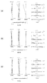
第1実施例について、図3、図4及び表1を用いて説明する。図3は、第1実施例に係るズームレンズZLの構成を示すとともに、広角端状態(W)から中間焦点距離状態(M)を経て望遠端状態(T)までの焦点距離状態の変化、すなわちズーミングの際の各レンズ群の移動の様子を示している。
(First embodiment)
A first embodiment will be described with reference to FIGS. 3 and 4 and Table 1. FIG. FIG. 3 shows the configuration of the zoom lens ZL according to the first embodiment, and the change in the focal length state from the wide-angle end state (W) through the intermediate focal length state (M) to the telephoto end state (T), that is, The movement of each lens group during zooming is shown.
本実施例に係るズームレンズZLにおいて、第1レンズ群G1は、光軸に沿って物体側から順に並んだ、物体側に凸面を向けた負メニスカスレンズL11と、光路を90度折り曲げるための直角プリズム(光路折り曲げ光学素子)Pと、両凸形状の正レンズL12とから構成されている。第2レンズ群G2は、光軸に沿って物体側から順に並んだ、両凹形状の負レンズL21と、両凹形状の負レンズL22と物体側に凸面を向けた正メニスカスレンズL23との接合レンズとから構成されている。第3レンズ群G3は、光軸に沿って物体側から順に並んだ、開口絞りSと、両凸形状の正レンズL31と、両凸形状の正レンズL32と両凹形状の負レンズL33との接合レンズとから構成されている。第4レンズ群G4は、両凸形状の正レンズL41と像面側に凸面を向けた負メニスカスレンズL42との接合レンズから構成されている。第5レンズ群G5は、両凸形状の正レンズL51と両凹形状の負レンズL52との接合レンズから構成されている。 In the zoom lens ZL according to the present embodiment, the first lens group G1 includes a negative meniscus lens L11 arranged in order from the object side along the optical axis and having a convex surface toward the object side, and a right angle for bending the optical path by 90 degrees. It is composed of a prism (optical path bending optical element) P and a biconvex positive lens L12. The second lens group G2 is composed of a biconcave negative lens L21, a biconcave negative lens L22, and a positive meniscus lens L23 having a convex surface facing the object, which are arranged in order from the object side along the optical axis. It consists of a lens. The third lens group G3 includes an aperture stop S, a biconvex positive lens L31, a biconvex positive lens L32, and a biconcave negative lens L33 arranged in order from the object side along the optical axis. And a cemented lens. The fourth lens group G4 includes a cemented lens which includes a biconvex positive lens L41 and a negative meniscus lens L42 having a convex surface directed toward the image surface side. The fifth lens group G5 includes a cemented lens of a biconvex positive lens L51 and a biconcave negative lens L52.
なお、本実施例に係るズームレンズZLでは、図2では直角プリズム(光路折り曲げ光学素子)Pにより光路を90度偏光しているが、図3で示すレンズ構成図にはこれを展開して示している。 In the zoom lens ZL according to the present embodiment, the optical path is polarized by 90 degrees by the right-angle prism (optical path bending optical element) P in FIG. 2, but this is shown expanded in the lens configuration diagram shown in FIG. ing.
表1に第1実施例における各諸元の表を示す。なお、表1における面番号1〜27は、図3に示す面1〜27に対応している。また、第1実施例において、第5面、第6面、第8面、第13面及び第18面の各レンズ面は、いずれも非球面形状に形成されている。 Table 1 shows a table of specifications in the first embodiment. In addition, the surface numbers 1-27 in Table 1 respond | correspond to the surfaces 1-27 shown in FIG. In the first embodiment, the fifth, sixth, eighth, thirteenth and eighteenth lens surfaces are all aspherical.
また、表中において、第1レンズ群G1と第2レンズ群G2との軸上空気間隔をd6とし、第2レンズ群G2と第3レンズ群G3との軸上空気間隔をd11とし、第3レンズ群G3と第4レンズ群G4との軸上空気間隔をd17とし、第4レンズ群G4と第5レンズ群G5との軸上空気間隔をd20とし、第5レンズ群G5とローパスフィルタLPSとの軸上空気間隔をd23とする。これらの軸上空気間隔、すなわちd6、d11、d17、d20及びd23はズーミングに際して変化する。また、表中において、上記の条件式(1)及び(2)に対応する値も示している。 In the table, the axial air space between the first lens group G1 and the second lens group G2 is d6, the axial air space between the second lens group G2 and the third lens group G3 is d11, and the third The axial air gap between the lens group G3 and the fourth lens group G4 is d17, the axial air gap between the fourth lens group G4 and the fifth lens group G5 is d20, the fifth lens group G5, the low-pass filter LPS, Let d23 be the axial air interval. These on-axis air intervals, d6, d11, d17, d20, and d23, change during zooming. In the table, values corresponding to the conditional expressions (1) and (2) are also shown.
(表1)
[レンズ諸元]
m r d nd νd
1 19.9501 0.7000 1.922860 20.88
2 8.7000 3.2000
3 ∞ 8.8000 1.846660 23.78
4 ∞ 0.2000
5* 17.9059 2.7500 1.693500 53.22
6* -17.5189 d6
7 -27.2642 0.5000 1.851350 40.10
8* 7.9847 1.0000
9 -54.2984 0.5000 1.755000 52.32
10 7.4016 1.2500 1.922860 20.88
11 56.8068 d11
12 ∞ 0.6500 (開口絞りS)
13* 8.2475 1.3500 1.743300 49.32
14 -61.2485 0.2500
15 8.0223 1.5500 1.497820 82.56
16 -22.1714 0.5000 1.883000 40.80
17 7.4033 d17
18* 13.6322 3.2000 1.693500 53.22
19 -6.6000 0.7500 1.846660 23.78
20 -12.8445 d20
21 15.6750 2.7000 1.497820 82.56
22 -7.6427 0.6000 1.834000 37.35
23 25.2498 d23
24 ∞ 0.2100 1.516800 64.10
25 ∞ 1.0000
26 ∞ 0.5000 1.516800 64.10
27 ∞ Bf
[非球面データ]
第5面
K=+1.0000,A4=-5.06590E-05,A6=-2.88220E-07,A8=2.10300E-09,A10=0.00000E-00
第6面
K=1.0000,A4=-3.13220E-06,A6=-1.55960E-07,A8=7.11450E-10,A10=0.00000E-00
第8面
K=-6.0414,A4=1.45720E-03,A6=-5.89340E-05,A8=1.70990E-06,A10=0.00000E-00
第13面
K=1.0000,A4=-1.51530E-04,A6=-4.91710E-06,A8=2.46130E-07,A10=0.00000E-00
第18面
K=-0.9600,A4=-1.04500E-04,A6=5.54390E-06,A8=-3.51050E-07,A10=8.82570E-09
[全体諸元]
ズーム比 3.77059
広角端 中間焦点距離 望遠端
f 5.10000 〜 10.94402 〜 19.23002
FNo 3.65391 〜 4.10566 〜 5.12431
ω 40.15140 〜 20.09895 〜 11.70281
Y 4.05000 〜 4.05000 〜 4.05000
TL 55.66618 〜 55.66618 〜 55.66618
Bf 0.88251 〜 0.88251 〜 0.88251
[ズーミングデータ]
可変間隔 広角端 中間焦点距離 望遠端
d6 0.60030 6.40430 8.96053
d11 8.96290 3.15891 0.60267
d17 7.35658 4.08679 1.10331
d20 2.71480 4.76819 5.57521
d23 2.98909 4.20547 6.38195
[ズームレンズ群データ]
群番号 群初面 群焦点距離
G1 1 17.80031
G2 7 -6.73928
G3 13 16.45217
G4 18 11.27694
G5 21 -24.41774
[条件式]
条件式(1) fG1/(fW×fT)(1/2)=1.7974
条件式(2) fG3/fG4=1.4589
(Table 1)
[Lens specifications]
m r d nd νd
1 19.9501 0.7000 1.922860 20.88
2 8.7000 3.2000
3 ∞ 8.8000 1.846660 23.78
4 ∞ 0.2000
5 * 17.9059 2.7500 1.693500 53.22
6 * -17.5189 d6
7 -27.2642 0.5000 1.851350 40.10
8 * 7.9847 1.0000
9 -54.2984 0.5000 1.755000 52.32
10 7.4016 1.2500 1.922860 20.88
11 56.8068 d11
12 ∞ 0.6500 (Aperture stop S)
13 * 8.2475 1.3500 1.743300 49.32
14 -61.2485 0.2500
15 8.0223 1.5500 1.497820 82.56
16 -22.1714 0.5000 1.883000 40.80
17 7.4033 d17
18 * 13.6322 3.2000 1.693500 53.22
19 -6.6000 0.7500 1.846660 23.78
20 -12.8445 d20
21 15.6750 2.7000 1.497820 82.56
22 -7.6427 0.6000 1.834000 37.35
23 25.2498 d23
24 ∞ 0.2100 1.516800 64.10
25 ∞ 1.0000
26 ∞ 0.5000 1.516800 64.10
27 ∞ Bf
[Aspherical data]
5th page
K = + 1.0000, A4 = -5.06590E-05, A6 = -2.88220E-07, A8 = 2.10300E-09, A10 = 0.00000E-00
6th page
K = 1.0000, A4 = -3.13220E-06, A6 = -1.55960E-07, A8 = 7.11450E-10, A10 = 0.00000E-00
8th page
K = -6.0414, A4 = 1.45720E-03, A6 = -5.89340E-05, A8 = 1.70990E-06, A10 = 0.00000E-00
13th page
K = 1.0000, A4 = -1.51530E-04, A6 = -4.91710E-06, A8 = 2.46130E-07, A10 = 0.00000E-00
18th page
K = -0.9600, A4 = -1.04500E-04, A6 = 5.54390E-06, A8 = -3.51050E-07, A10 = 8.82570E-09
[Overall specifications]
Zoom ratio 3.77059
Wide angle end Intermediate focal length Telephoto end f 5.10000 to 10.94402 to 19.23002
FNo 3.65391 to 4.10566 to 5.12431
ω 40.15140 〜 20.09895 〜 11.70281
Y 4.05000 to 4.05000 to 4.05000
TL 55.66618-55.66618-55.66618
Bf 0.88251 to 0.88251 to 0.88251
[Zooming data]
Variable interval Wide angle end Intermediate focal length Telephoto end
d6 0.60030 6.40430 8.96053
d11 8.96290 3.15891 0.60267
d17 7.35658 4.08679 1.10331
d20 2.71480 4.76819 5.57521
d23 2.98909 4.20547 6.38195
[Zoom lens group data]
Group number Group first surface Group
G2 7 -6.73928
G3 13 16.45217
G5 21 -24.41774
[Conditional expression]
Conditional expression (1) fG1 / (fW × fT) (1/2) = 1.7974
Conditional expression (2) fG3 / fG4 = 1.4589
表1に示す諸元の表から、本実施例に係るズームレンズZLでは、上記条件式(1)及び(2)を全て満たすことが分かる。 From the specification table shown in Table 1, it can be seen that the zoom lens ZL according to the present example satisfies all the conditional expressions (1) and (2).
図4は、第1実施例の諸収差図であり、(a)は広角端状態における無限遠合焦状態での諸収差図であり、(b)は中間焦点距離状態における無限遠合焦状態での諸収差図であり、(c)は望遠端状態における無限遠合焦状態での諸収差図である。 4A and 4B are graphs showing various aberrations of the first example. FIG. 4A is a diagram showing various aberrations in the infinitely focused state at the wide-angle end state, and FIG. 4B is the infinitely focused state in the intermediate focal length state. FIG. 4C is a diagram illustrating various aberrations in the infinitely focused state in the telephoto end state.
各収差図において、FNOはFナンバーを、Yは像高を示している。球面収差を示す収差図において、実線は球面収差を示し、破線はサインコンディション(正弦条件)を示す。また、非点収差を示す収差図において、実線はサジタル像面を示し、破線はメリジオナル像面を示す。さらに、コマ収差において、実線はメリジオナルコマを示し、破線はサジタルコマを示す。以上の収差図の説明は、他の実施例においても同様とし、その説明を省略する。 In each aberration diagram, FNO indicates an F number, and Y indicates an image height. In the aberration diagram showing spherical aberration, the solid line shows spherical aberration, and the broken line shows sine condition (sine condition). In the aberration diagrams showing astigmatism, the solid line indicates the sagittal image plane, and the broken line indicates the meridional image plane. Further, in coma aberration, a solid line indicates a meridional coma, and a broken line indicates a sagittal coma. The explanation of the above aberration diagrams is the same in the other examples, and the explanation is omitted.
各収差図から明らかなように、第1実施例では、広角端状態から望遠端状態までの各焦点距離状態において諸収差が良好に補正され、優れた結像性能を有することが分かる。その結果、第1実施例のズームレンズZLを搭載することにより、デジタルスチルカメラCAM(光学機器。図1参照)においても、優れた光学性能を確保することができる。 As is apparent from the respective aberration diagrams, in the first example, it is understood that various aberrations are well corrected in each focal length state from the wide-angle end state to the telephoto end state, and excellent imaging performance is obtained. As a result, by mounting the zoom lens ZL of the first embodiment, excellent optical performance can be ensured also in the digital still camera CAM (optical apparatus, see FIG. 1).
(第2実施例)
第2実施例について、図5、図6及び表2を用いて説明する。図5は、第2実施例に係るズームレンズZLの構成を示すとともに、広角端状態(W)から中間焦点距離状態(M)を経て望遠端状態(T)までの焦点距離状態の変化、すなわちズーミングの際の各レンズ群の移動の様子を示している。
(Second embodiment)
A second embodiment will be described with reference to FIGS. 5 and 6 and Table 2. FIG. FIG. 5 shows the configuration of the zoom lens ZL according to the second embodiment, and changes in the focal length state from the wide-angle end state (W) through the intermediate focal length state (M) to the telephoto end state (T), that is, The movement of each lens group during zooming is shown.
本実施例に係るズームレンズZLにおいて、第1レンズ群G1は、光軸に沿って物体側から順に並んだ、物体側に凸面を向けた負メニスカスレンズL11と、光路を90度折り曲げるための直角プリズム(光路折り曲げ光学素子)Pと、両凸形状の正レンズL12とから構成されている。第2レンズ群G2は、光軸に沿って物体側から順に並んだ、両凹形状の負レンズL21と、両凹形状の負レンズL22と物体側に凸面を向けた正メニスカスレンズL23との接合レンズとから構成されている。第3レンズ群G3は、光軸に沿って物体側から順に並んだ、開口絞りSと、両凸形状の正レンズL31と、両凸形状の正レンズL32と両凹形状の負レンズL33との接合レンズとから構成されている。第4レンズ群G4は、両凸形状の正レンズL41と像面側に凸面を向けた負メニスカスレンズL42との接合レンズから構成されている。第5レンズ群G5は、両凸形状の正レンズL51と両凹形状の負レンズL52との接合レンズから構成されている。 In the zoom lens ZL according to the present embodiment, the first lens group G1 includes a negative meniscus lens L11 arranged in order from the object side along the optical axis and having a convex surface toward the object side, and a right angle for bending the optical path by 90 degrees. It is composed of a prism (optical path bending optical element) P and a biconvex positive lens L12. The second lens group G2 is composed of a biconcave negative lens L21, a biconcave negative lens L22, and a positive meniscus lens L23 having a convex surface facing the object, which are arranged in order from the object side along the optical axis. It consists of a lens. The third lens group G3 includes an aperture stop S, a biconvex positive lens L31, a biconvex positive lens L32, and a biconcave negative lens L33 arranged in order from the object side along the optical axis. And a cemented lens. The fourth lens group G4 includes a cemented lens which includes a biconvex positive lens L41 and a negative meniscus lens L42 having a convex surface directed toward the image surface side. The fifth lens group G5 includes a cemented lens of a biconvex positive lens L51 and a biconcave negative lens L52.
なお、本実施例に係るズームレンズZLでは、図2では直角プリズム(光路折り曲げ光学素子)Pにより光路を90度偏光しているが、図5で示すレンズ構成図にはこれを展開して示している。 In the zoom lens ZL according to the present embodiment, the optical path is polarized by 90 degrees by the right-angle prism (optical path bending optical element) P in FIG. 2, but this is shown expanded in the lens configuration diagram shown in FIG. ing.
表2に第2実施例における各諸元の表を示す。なお、表2における面番号1〜27は、図5に示す面1〜27に対応している。また、第2実施例において、第5面、第6面、第8面、第13面及び第18面の各レンズ面は、いずれも非球面形状に形成されている。
Table 2 shows a table of specifications in the second embodiment. The
また、表中において、第1レンズ群G1と第2レンズ群G2との軸上空気間隔をd6とし、第2レンズ群G2と第3レンズ群G3との軸上空気間隔をd11とし、第3レンズ群G3と第4レンズ群G4との軸上空気間隔をd17とし、第4レンズ群G4と第5レンズ群G5との軸上空気間隔をd20とし、第5レンズ群G5とローパスフィルタLPSとの軸上空気間隔をd23とする。これらの軸上空気間隔、すなわちd6、d11、d17、d20及びd23はズーミングに際して変化する。また、表中において、上記の条件式(1)及び(2)に対応する値も示している。 In the table, the axial air space between the first lens group G1 and the second lens group G2 is d6, the axial air space between the second lens group G2 and the third lens group G3 is d11, and the third The axial air gap between the lens group G3 and the fourth lens group G4 is d17, the axial air gap between the fourth lens group G4 and the fifth lens group G5 is d20, the fifth lens group G5, the low-pass filter LPS, Let d23 be the axial air interval. These on-axis air intervals, d6, d11, d17, d20, and d23, change during zooming. In the table, values corresponding to the conditional expressions (1) and (2) are also shown.
(表2)
[レンズ諸元]
m r d nd νd
1 19.9615 0.7000 1.922860 20.88
2 8.7000 3.2000
3 ∞ 8.8000 1.846660 23.78
4 ∞ 0.2000
5* 17.9205 2.7500 1.693500 53.22
6* -17.5034 d6
7 -27.1347 0.5000 1.851350 40.10
8* 7.9977 1.0000
9 -58.8634 0.5000 1.755000 52.32
10 7.3322 1.2500 1.922860 20.88
11 52.8991 d11
12 ∞ 0.6500 (開口絞りS)
13* 8.2581 1.3500 1.743300 49.32
14 -62.0396 0.2500
15 8.0088 1.5500 1.497820 82.56
16 -22.4561 0.5000 1.883000 40.80
17 7.4062 d17
18* 13.6500 3.2000 1.693500 53.22
19 -6.6000 0.7500 1.846660 23.78
20 -12.8315 d20
21 15.5609 2.7000 1.497820 82.56
22 -7.6608 0.6000 1.834000 37.35
23 24.9564 d23
24 ∞ 0.2100 1.516800 64.10
25 ∞ 1.0000
26 ∞ 0.5000 1.516800 64.10
27 ∞ Bf
[非球面データ]
第5面
K=1.0000,A4=-5.12440E-05,A6=-2.65390E-07,A8=1.18610E-09,A10=0.00000E-00
第6面
K=1.0000,A4=-3.61240E-06,A6=-1.40480E-07,A8=-1.27480E-11,A10=0.00000E-00
第8面
K=-6.0328,A4=1.44940E-03,A6=-5.86840E-05,A8=1.70190E-06,A10=0.00000E-00
第13面
K=1.0000,A4=-1.54860E-04,A6=-3.65500E-06,A8=1.22820E-07,A10=0.00000E-00
第18面
K=-1.4430,A4=-8.03000E-05,A6=5.29170E-06,A8=-3.46490E-07,A10=8.79560E-09
[全体諸元]
ズーム比 3.77059
広角端 中間焦点距離 望遠端
f 5.10000 〜 10.94402 〜 19.23002
FNo 3.65240 〜 4.10338 〜 5.12097
ω 40.15163 〜 20.09885 〜 11.70269
Y 4.05000 〜 4.05000 〜 4.05000
TL 55.66857 〜 55.66857 〜 55.66857
Bf 0.88251 〜 0.88251 〜 0.88251
[ズーミングデータ]
可変間隔 広角端 中間焦点距離 望遠端
d6 0.60030 6.40430 8.96053
d11 8.96290 3.15891 0.60267
d17 7.36000 4.09021 1.10673
d20 2.70073 4.75412 5.56114
d23 3.00213 4.21851 6.39499
[ズームレンズ群データ]
群番号 群初面 群焦点距離
G1 1 17.80031
G2 7 -6.73928
G3 13 16.45217
G4 18 11.27694
G5 21 -24.41774
[条件式]
条件式(1) fG1/(fW×fT)(1/2)=1.7974
条件式(2) fG3/fG4=1.4589
(Table 2)
[Lens specifications]
m r d nd νd
1 19.9615 0.7000 1.922860 20.88
2 8.7000 3.2000
3 ∞ 8.8000 1.846660 23.78
4 ∞ 0.2000
5 * 17.9205 2.7500 1.693500 53.22
6 * -17.5034 d6
7 -27.1347 0.5000 1.851350 40.10
8 * 7.9977 1.0000
9 -58.8634 0.5000 1.755000 52.32
10 7.3322 1.2500 1.922860 20.88
11 52.8991 d11
12 ∞ 0.6500 (Aperture stop S)
13 * 8.2581 1.3500 1.743300 49.32
14 -62.0396 0.2500
15 8.0088 1.5500 1.497820 82.56
16 -22.4561 0.5000 1.883000 40.80
17 7.4062 d17
18 * 13.6500 3.2000 1.693500 53.22
19 -6.6000 0.7500 1.846660 23.78
20 -12.8315 d20
21 15.5609 2.7000 1.497820 82.56
22 -7.6608 0.6000 1.834000 37.35
23 24.9564 d23
24 ∞ 0.2100 1.516800 64.10
25 ∞ 1.0000
26 ∞ 0.5000 1.516800 64.10
27 ∞ Bf
[Aspherical data]
5th page
K = 1.0000, A4 = -5.12440E-05, A6 = -2.65390E-07, A8 = 1.18610E-09, A10 = 0.00000E-00
6th page
K = 1.0000, A4 = -3.61240E-06, A6 = -1.40480E-07, A8 = -1.27480E-11, A10 = 0.00000E-00
8th page
K = -6.0328, A4 = 1.44940E-03, A6 = -5.86840E-05, A8 = 1.70190E-06, A10 = 0.00000E-00
13th page
K = 1.0000, A4 = -1.54860E-04, A6 = -3.65500E-06, A8 = 1.22820E-07, A10 = 0.00000E-00
18th page
K = -1.4430, A4 = -8.03000E-05, A6 = 5.29170E-06, A8 = -3.46490E-07, A10 = 8.79560E-09
[Overall specifications]
Zoom ratio 3.77059
Wide angle end Intermediate focal length Telephoto end f 5.10000 to 10.94402 to 19.23002
FNo 3.65240-4.10338-5.12097
ω 40.15163 〜 20.09885 〜 11.70269
Y 4.05000 to 4.05000 to 4.05000
TL 55.66857 to 55.66857 to 55.66857
Bf 0.88251 to 0.88251 to 0.88251
[Zooming data]
Variable interval Wide angle end Intermediate focal length Telephoto end
d6 0.60030 6.40430 8.96053
d11 8.96290 3.15891 0.60267
d17 7.36000 4.09021 1.10673
d20 2.70073 4.75412 5.56114
d23 3.00213 4.21851 6.39499
[Zoom lens group data]
Group number Group first surface Group
G2 7 -6.73928
G3 13 16.45217
G5 21 -24.41774
[Conditional expression]
Conditional expression (1) fG1 / (fW × fT) (1/2) = 1.7974
Conditional expression (2) fG3 / fG4 = 1.4589
表2に示す諸元の表から、本実施例に係るズームレンズZLでは、上記条件式(1)及び(2)を全て満たすことが分かる。 From the table of specifications shown in Table 2, it can be seen that the zoom lens ZL according to the present example satisfies all the conditional expressions (1) and (2).
図6は、第2実施例の諸収差図であり、(a)は広角端状態における無限遠合焦状態での諸収差図であり、(b)は中間焦点距離状態における無限遠合焦状態での諸収差図であり、(c)は望遠端状態における無限遠合焦状態での諸収差図である。 6A and 6B are graphs showing various aberrations of the second example, wherein FIG. 6A is a diagram showing various aberrations in the infinite focus state in the wide-angle end state, and FIG. 6B is an infinite focus state in the intermediate focal length state. FIG. 4C is a diagram illustrating various aberrations in the infinitely focused state in the telephoto end state.
各収差図から明らかなように、第2実施例では、広角端状態から望遠端状態までの各焦点距離状態において諸収差が良好に補正され、優れた結像性能を有することが分かる。その結果、第2実施例のズームレンズZLを搭載することにより、デジタルスチルカメラCAM(光学機器。図1参照)においても、優れた光学性能を確保することができる。 As is apparent from the respective aberration diagrams, in the second example, it is understood that various aberrations are favorably corrected in each focal length state from the wide-angle end state to the telephoto end state, and excellent imaging performance is obtained. As a result, by installing the zoom lens ZL of the second embodiment, excellent optical performance can be ensured also in the digital still camera CAM (optical apparatus, see FIG. 1).
(第3実施例)
第3実施例について、図7、図8及び表3を用いて説明する。図7は、第3実施例に係るズームレンズZLの構成を示すとともに、広角端状態(W)から中間焦点距離状態(M)を経て望遠端状態(T)までの焦点距離状態の変化、すなわちズーミングの際の各レンズ群の移動の様子を示している。
(Third embodiment)
A third embodiment will be described with reference to FIGS. FIG. 7 shows the configuration of the zoom lens ZL according to Example 3, and the change in the focal length state from the wide-angle end state (W) through the intermediate focal length state (M) to the telephoto end state (T), that is, The movement of each lens group during zooming is shown.
本実施例に係るズームレンズZLにおいて、第1レンズ群G1は、光軸に沿って物体側から順に並んだ、物体側に凸面を向けた負メニスカスレンズL11と、光路を90度折り曲げるための直角プリズム(光路折り曲げ光学素子)Pと、両凸形状の正レンズL12とから構成されている。第2レンズ群G2は、光軸に沿って物体側から順に並んだ、両凹形状の負レンズL21と、両凹形状の負レンズL22と両凸形状の正レンズL23との接合レンズから構成されている。第3レンズ群G3は、光軸に沿って物体側から順に並んだ、開口絞りSと、両凸形状の正レンズL31と、両凸形状の正レンズL32と両凹形状の負レンズL33との接合レンズから構成されている。第4レンズ群G4は、両凸形状の正レンズL41と像面側に凸面を向けた負メニスカスレンズL42との接合レンズから構成されている。第5レンズ群G5は、両凸形状の正レンズL51と両凹形状の負レンズL52との接合レンズから構成されている。 In the zoom lens ZL according to the present embodiment, the first lens group G1 includes a negative meniscus lens L11 arranged in order from the object side along the optical axis and having a convex surface toward the object side, and a right angle for bending the optical path by 90 degrees. It is composed of a prism (optical path bending optical element) P and a biconvex positive lens L12. The second lens group G2 includes a biconcave negative lens L21, a cemented lens of a biconcave negative lens L22, and a biconvex positive lens L23, which are arranged in order from the object side along the optical axis. ing. The third lens group G3 includes an aperture stop S, a biconvex positive lens L31, a biconvex positive lens L32, and a biconcave negative lens L33 arranged in order from the object side along the optical axis. It consists of a cemented lens. The fourth lens group G4 includes a cemented lens which includes a biconvex positive lens L41 and a negative meniscus lens L42 having a convex surface directed toward the image surface side. The fifth lens group G5 includes a cemented lens of a biconvex positive lens L51 and a biconcave negative lens L52.
なお、本実施例に係るズームレンズZLでは、図2では直角プリズム(光路折り曲げ光学素子)Pにより光路を90度偏光しているが、図7で示すレンズ構成図にはこれを展開して示している。 In the zoom lens ZL according to the present embodiment, the optical path is polarized by 90 degrees by the right-angle prism (optical path bending optical element) P in FIG. 2, but this is shown expanded in the lens configuration diagram shown in FIG. ing.
表3に第3実施例における各諸元の表を示す。なお、表3における面番号1〜27は、図7に示す面1〜27に対応している。また、第3実施例において、第5面、第6面、第8面、第13面及び第18面の各レンズ面は、いずれも非球面形状に形成されている。 Table 3 shows a table of specifications in the third embodiment. In addition, the surface numbers 1-27 in Table 3 respond | correspond to the surfaces 1-27 shown in FIG. In the third embodiment, the lens surfaces of the fifth surface, the sixth surface, the eighth surface, the thirteenth surface, and the eighteenth surface are all aspherical.
また、表中において、第1レンズ群G1と第2レンズ群G2との軸上空気間隔をd6とし、第2レンズ群G2と第3レンズ群G3との軸上空気間隔をd11とし、第3レンズ群G3と第4レンズ群G4との軸上空気間隔をd17とし、第4レンズ群G4と第5レンズ群G5との軸上空気間隔をd20とし、第5レンズ群G5とローパスフィルタLPSとの軸上空気間隔をd23とする。これらの軸上空気間隔、すなわちd6、d11、d17、d20及びd23はズーミングに際して変化する。また、表中において、上記の条件式(1)及び(2)に対応する値も示している。 In the table, the axial air space between the first lens group G1 and the second lens group G2 is d6, the axial air space between the second lens group G2 and the third lens group G3 is d11, and the third The axial air gap between the lens group G3 and the fourth lens group G4 is d17, the axial air gap between the fourth lens group G4 and the fifth lens group G5 is d20, the fifth lens group G5, the low-pass filter LPS, Let d23 be the axial air interval. These on-axis air intervals, d6, d11, d17, d20, and d23, change during zooming. In the table, values corresponding to the conditional expressions (1) and (2) are also shown.
(表3)
[レンズ諸元]
m r d nd νd
1 20.6254 0.8000 1.922860 20.88
2 8.7071 3.1000
3 ∞ 8.8000 1.846663 23.78
4 ∞ 0.2000
5* 17.1808 2.9437 1.693500 53.20
6* -17.3055 d6
7 -32.8187 0.5000 1.851348 40.10
8* 7.6104 0.9639
9 -22.3858 0.5000 1.755000 52.32
10 8.4734 1.2819 1.922860 20.88
11 -439.1103 d11
12 ∞ 0.7000 (開口絞りS)
13* 7.6741 1.3607 1.743300 49.32
14 -47.0801 0.1000
15 8.5164 1.4942 1.497820 82.56
16 -19.4470 0.5000 1.883000 40.81
17 7.1936 d17
18* 14.2071 3.0001 1.693500 53.20
19 -6.4457 0.6371 1.846663 23.78
20 -12.9522 d20
21 18.7873 3.0000 1.497820 82.56
22 -7.0852 0.8000 1.834000 37.35
23 37.6970 d23
24 ∞ 0.6500 1.544370 70.51
25 ∞ 1.0000
26 ∞ 0.5000 1.516798 64.19
27 ∞ Bf
[非球面データ]
第5面
K=0.3559,A4=-3.81790E-05,A6=-1.63840E-07,A8=4.14210E-09,A10=-1.55190E-10
第6面
K=1.0000,A4=7.40520E-07,A6=9.98320E-08,A8=-6.21800E-09,A10=0.00000E-00
第8面
K=-3.8061,A4=1.12080E-03,A6=-3.44130E-05,A8=1.21990E-06,A10=0.00000E-00
第13面
K=-0.0659,A4=9.23200E-05,A6=-7.92830E-07,A8=6.31960E-08,A10=0.00000E-00
第18面
K=3.4103,A4=-2.86920E-04,A6=3.45980E-06,A8=-3.38290E-07,A10=8.67190E-09
[全体諸元]
ズーム比 3.77059
広角端 中間焦点距離 望遠端
f 5.10000 〜 10.94402 〜 19.23002
FNo 3.67776 〜 4.10468 〜 5.06328
ω 40.12961 〜 19.98522 〜 11.70758
Y 4.05000 〜 4.05000 〜 4.05000
TL 55.39792 〜 55.39792 〜 55.39792
Bf 0.60006 〜 0.60006 〜 0.60006
[ズーミングデータ]
可変間隔 広角端 中間焦点距離 望遠端
d6 0.60000 6.38859 8.93805
d11 8.93807 3.14948 0.60000
d17 7.02077 3.82237 1.00000
d20 2.65276 4.92779 5.37140
d23 2.75469 3.67804 6.05680
[ズームレンズ群データ]
群番号 群初面 群焦点距離
G1 1 17.19755
G2 7 -6.63362
G3 13 15.87834
G4 18 11.59948
G5 21 -25.27814
[条件式]
条件式(1) fG1/(fW×fT)(1/2)=1.7366
条件式(2) fG3/fG4=1.3689
(Table 3)
[Lens specifications]
m r d nd νd
1 20.6254 0.8000 1.922860 20.88
2 8.7071 3.1000
3 ∞ 8.8000 1.846663 23.78
4 ∞ 0.2000
5 * 17.1808 2.9437 1.693500 53.20
6 * -17.3055 d6
7 -32.8187 0.5000 1.851348 40.10
8 * 7.6104 0.9639
9 -22.3858 0.5000 1.755000 52.32
10 8.4734 1.2819 1.922860 20.88
11 -439.1103 d11
12 ∞ 0.7000 (Aperture stop S)
13 * 7.6741 1.3607 1.743300 49.32
14 -47.0801 0.1000
15 8.5164 1.4942 1.497820 82.56
16 -19.4470 0.5000 1.883000 40.81
17 7.1936 d17
18 * 14.2071 3.0001 1.693500 53.20
19 -6.4457 0.6371 1.846663 23.78
20 -12.9522 d20
21 18.7873 3.0000 1.497820 82.56
22 -7.0852 0.8000 1.834000 37.35
23 37.6970 d23
24 ∞ 0.6500 1.544370 70.51
25 ∞ 1.0000
26 ∞ 0.5000 1.516798 64.19
27 ∞ Bf
[Aspherical data]
5th page
K = 0.3559, A4 = -3.81790E-05, A6 = -1.63840E-07, A8 = 4.14210E-09, A10 = -1.55190E-10
6th page
K = 1.0000, A4 = 7.40520E-07, A6 = 9.98320E-08, A8 = -6.21800E-09, A10 = 0.00000E-00
8th page
K = -3.8061, A4 = 1.12080E-03, A6 = -3.44130E-05, A8 = 1.21990E-06, A10 = 0.00000E-00
13th page
K = -0.0659, A4 = 9.23200E-05, A6 = -7.92830E-07, A8 = 6.31960E-08, A10 = 0.00000E-00
18th page
K = 3.4103, A4 = -2.86920E-04, A6 = 3.45980E-06, A8 = -3.38290E-07, A10 = 8.67190E-09
[Overall specifications]
Zoom ratio 3.77059
Wide angle end Intermediate focal length Telephoto end f 5.10000 to 10.94402 to 19.23002
FNo 3.67776 to 4.10468 to 5.06328
ω 40.12961 〜 19.98522 〜 11.70758
Y 4.05000 to 4.05000 to 4.05000
TL 55.39792 to 55.39792 to 55.39792
Bf 0.60006 to 0.60006 to 0.60006
[Zooming data]
Variable interval Wide angle end Intermediate focal length Telephoto end
d6 0.60000 6.38859 8.93805
d11 8.93807 3.14948 0.60000
d17 7.02077 3.82237 1.00000
d20 2.65276 4.92779 5.37140
d23 2.75469 3.67804 6.05680
[Zoom lens group data]
Group number Group first surface Group
G2 7 -6.63362
G3 13 15.87834
G5 21 -25.27814
[Conditional expression]
Conditional expression (1) fG1 / (fW × fT) (1/2) = 1.7366
Conditional expression (2) fG3 / fG4 = 1.3689
表3に示す諸元の表から、本実施例に係るズームレンズZLでは、上記条件式(1)及び(2)を全て満たすことが分かる。 From the table of specifications shown in Table 3, it can be seen that the zoom lens ZL according to the present example satisfies all the conditional expressions (1) and (2).
図8は、第3実施例の諸収差図であり、(a)は広角端状態における無限遠合焦状態での諸収差図であり、(b)は中間焦点距離状態における無限遠合焦状態での諸収差図であり、(c)は望遠端状態における無限遠合焦状態での諸収差図である。 8A and 8B are graphs showing various aberrations of the third example. FIG. 8A is a diagram showing various aberrations in the infinitely focused state at the wide-angle end state, and FIG. 8B is an infinitely focused state in the intermediate focal length state. FIG. 4C is a diagram illustrating various aberrations in the infinitely focused state in the telephoto end state.
各収差図から明らかなように、第3実施例では、広角端状態から望遠端状態までの各焦点距離状態において諸収差が良好に補正され、優れた結像性能を有することが分かる。その結果、第3実施例のズームレンズZLを搭載することにより、デジタルスチルカメラCAM(光学機器。図1参照)においても、優れた光学性能を確保することができる。 As is apparent from the respective aberration diagrams, in the third example, it is understood that various aberrations are well corrected in each focal length state from the wide-angle end state to the telephoto end state, and excellent imaging performance is obtained. As a result, by mounting the zoom lens ZL of the third embodiment, excellent optical performance can be ensured also in the digital still camera CAM (optical apparatus, see FIG. 1).
(第4実施例)
第4実施例について、図9、図10及び表4を用いて説明する。図9は、第4実施例に係るズームレンズZLの構成を示すとともに、広角端状態(W)から中間焦点距離状態(M)を経て望遠端状態(T)までの焦点距離状態の変化、すなわちズーミングの際の各レンズ群の移動の様子を示している。
(Fourth embodiment)
The fourth embodiment will be described with reference to FIGS. 9 and 10 and Table 4. FIG. FIG. 9 shows the configuration of the zoom lens ZL according to Example 4, and the change in the focal length state from the wide-angle end state (W) through the intermediate focal length state (M) to the telephoto end state (T). The movement of each lens group during zooming is shown.
本実施例に係るズームレンズZLにおいて、第1レンズ群G1は、光軸に沿って物体側から順に並んだ、物体側に凸面を向けた負メニスカスレンズL11と、光路を90度折り曲げるための直角プリズム(光路折り曲げ光学素子)Pと、両凸形状の正レンズL12とから構成されている。第2レンズ群G2は、光軸に沿って物体側から順に並んだ、両凹形状の負レンズL21と、両凹形状の負レンズL22と物体側に凸面を向けた正メニスカスレンズL23との接合レンズとから構成されている。第3レンズ群G3は、光軸に沿って物体側から順に並んだ、開口絞りSと、両凸形状の正レンズL31と、両凸形状の正レンズL32と両凹形状の負レンズL33との接合レンズから構成されている。第4レンズ群G4は、両凸形状の正レンズL41と像面側に凸面を向けた負メニスカスレンズL42との接合レンズから構成されている。第5レンズ群G5は、両凸形状の正レンズL51と両凹形状の負レンズL52との接合レンズから構成されている。 In the zoom lens ZL according to the present embodiment, the first lens group G1 includes a negative meniscus lens L11 arranged in order from the object side along the optical axis and having a convex surface toward the object side, and a right angle for bending the optical path by 90 degrees. It is composed of a prism (optical path bending optical element) P and a biconvex positive lens L12. The second lens group G2 is composed of a biconcave negative lens L21, a biconcave negative lens L22, and a positive meniscus lens L23 having a convex surface facing the object, which are arranged in order from the object side along the optical axis. It consists of a lens. The third lens group G3 includes an aperture stop S, a biconvex positive lens L31, a biconvex positive lens L32, and a biconcave negative lens L33 arranged in order from the object side along the optical axis. It consists of a cemented lens. The fourth lens group G4 includes a cemented lens which includes a biconvex positive lens L41 and a negative meniscus lens L42 having a convex surface directed toward the image surface side. The fifth lens group G5 includes a cemented lens of a biconvex positive lens L51 and a biconcave negative lens L52.
なお、本実施例に係るズームレンズZLでは、図2では直角プリズム(光路折り曲げ光学素子)Pにより光路を90度偏光しているが、図9で示すレンズ構成図にはこれを展開して示している。 In the zoom lens ZL according to the present embodiment, the optical path is polarized by 90 degrees by the right-angle prism (optical path bending optical element) P in FIG. 2, but this is shown expanded in the lens configuration diagram shown in FIG. ing.
表4に第4実施例における各諸元の表を示す。なお、表4における面番号1〜27は、図9に示す面1〜27に対応している。また、第4実施例において、第5面、第6面、第8面、第13面及び第18面の各レンズ面は、いずれも非球面形状に形成されている。 Table 4 shows a table of specifications in the fourth embodiment. In addition, the surface numbers 1-27 in Table 4 respond | correspond to the surfaces 1-27 shown in FIG. In the fourth embodiment, the lens surfaces of the fifth surface, the sixth surface, the eighth surface, the thirteenth surface, and the eighteenth surface are all aspherical.
また、表中において、第1レンズ群G1と第2レンズ群G2との軸上空気間隔をd6とし、第2レンズ群G2と第3レンズ群G3との軸上空気間隔をd11とし、第3レンズ群G3と第4レンズ群G4との軸上空気間隔をd17とし、第4レンズ群G4と第5レンズ群G5との軸上空気間隔をd20とし、第5レンズ群G5とローパスフィルタLPSとの軸上空気間隔をd23とする。これらの軸上空気間隔、すなわちd6、d11、d17、d20及びd23はズーミングに際して変化する。また、表中において、上記の条件式(1)及び(2)に対応する値も示している。 In the table, the axial air space between the first lens group G1 and the second lens group G2 is d6, the axial air space between the second lens group G2 and the third lens group G3 is d11, and the third The axial air gap between the lens group G3 and the fourth lens group G4 is d17, the axial air gap between the fourth lens group G4 and the fifth lens group G5 is d20, the fifth lens group G5, the low-pass filter LPS, Let d23 be the axial air interval. These on-axis air intervals, d6, d11, d17, d20, and d23, change during zooming. In the table, values corresponding to the conditional expressions (1) and (2) are also shown.
(表4)
[レンズ諸元]
m r d nd νd
1 20.0815 0.8000 1.922860 20.88
2 8.6070 3.1000
3 ∞ 8.8000 1.846663 23.78
4 ∞ 0.2000
5* 17.5186 2.9127 1.693500 53.20
6* -17.0259 d6
7 -25.0758 0.5000 1.851348 40.10
8 7.6129 0.8682
9 -45.0590 0.5000 1.755000 52.32
10 7.6315 1.2939 1.922860 20.88
11 93.0936 d11
12 ∞ 0.7000 (開口絞りS)
13* 8.1247 1.3227 1.743300 49.32
14 -58.0582 0.4304
15 7.4541 1.5203 1.497820 82.56
16 -24.3167 0.5000 1.883000 40.81
17 7.0271 d17
18* 13.6932 3.0000 1.693500 53.20
19 -6.4316 0.8000 1.846663 23.78
20 -13.2158 d20
21 22.7931 3.0000 1.497820 82.56
22 -7.6879 0.8000 1.834000 37.35
23 49.0304 d23
24 ∞ 0.6500 1.544370 70.51
25 ∞ 1.0000
26 ∞ 0.5000 1.516798 64.19
27 ∞ Bf
[非球面データ]
第5面
K=-1.4515,A4=-6.09810E-06,A6=2.64910E-08,A8=1.58740E-09,A10=-3.14790E-10
第6面
K=1.0000,A4=-1.09620E-05,A6=5.66980E-07,A8=-1.89040E-08,A10=0.00000E-00
第8面
K=-4.8573,A4=1.32390E-03,A6=-5.14330E-05,A8=1.49140E-06,A10=0.00000E-00
第13面
K=-0.0844,A4=8.50870E-05,A6=-1.80840E-06,A8=1.32780E-07,A10=0.00000E-00
第18面
K=0.2532,A4=-1.68380E-04,A6=5.07310E-06,A8=-2.82520E-07,A10=6.17250E-09
[全体諸元]
ズーム比 3.77057
広角端 中間焦点距離 望遠端
f 5.10000 〜 10.99991 〜 19.22992
FNo 3.69295 〜 4.06591 〜 5.03525
ω 40.12682 〜 20.00748 〜 11.72370
Y 4.05000 〜 4.05000 〜 4.05000
TL 55.83455 〜 55.83455 〜 55.83455
Bf 0.60006 〜 0.60006 〜 0.60006
[ズーミングデータ]
可変間隔 広角端 中間焦点距離 望遠端
d6 0.60000 6.46434 8.95884
d11 8.95885 3.09452 0.60000
d17 7.31675 3.95844 1.00000
d20 2.39504 4.94009 5.40532
d23 2.76567 3.57890 6.07213
[ズームレンズ群データ]
群番号 群初面 群焦点距離
G1 1 17.23225
G2 7 -6.55828
G3 13 15.24569
G4 18 11.56329
G5 21 -27.48089
[条件式]
条件式(1) fG1/(fW×fT)(1/2)=1.7401
条件式(2) fG3/fG4=1.3185
(Table 4)
[Lens specifications]
m r d nd νd
1 20.0815 0.8000 1.922860 20.88
2 8.6070 3.1000
3 ∞ 8.8000 1.846663 23.78
4 ∞ 0.2000
5 * 17.5186 2.9127 1.693500 53.20
6 * -17.0259 d6
7 -25.0758 0.5000 1.851348 40.10
8 7.6129 0.8682
9 -45.0590 0.5000 1.755000 52.32
10 7.6315 1.2939 1.922860 20.88
11 93.0936 d11
12 ∞ 0.7000 (Aperture stop S)
13 * 8.1247 1.3227 1.743300 49.32
14 -58.0582 0.4304
15 7.4541 1.5203 1.497820 82.56
16 -24.3167 0.5000 1.883000 40.81
17 7.0271 d17
18 * 13.6932 3.0000 1.693500 53.20
19 -6.4316 0.8000 1.846663 23.78
20 -13.2158 d20
21 22.7931 3.0000 1.497820 82.56
22 -7.6879 0.8000 1.834000 37.35
23 49.0304 d23
24 ∞ 0.6500 1.544370 70.51
25 ∞ 1.0000
26 ∞ 0.5000 1.516798 64.19
27 ∞ Bf
[Aspherical data]
5th page
K = -1.4515, A4 = -6.09810E-06, A6 = 2.64910E-08, A8 = 1.58740E-09, A10 = -3.14790E-10
6th page
K = 1.0000, A4 = -1.09620E-05, A6 = 5.66980E-07, A8 = -1.89040E-08, A10 = 0.00000E-00
8th page
K = -4.8573, A4 = 1.32390E-03, A6 = -5.14330E-05, A8 = 1.49140E-06, A10 = 0.00000E-00
13th page
K = -0.0844, A4 = 8.50870E-05, A6 = -1.80840E-06, A8 = 1.32780E-07, A10 = 0.00000E-00
18th page
K = 0.2532, A4 = -1.68380E-04, A6 = 5.07310E-06, A8 = -2.82520E-07, A10 = 6.17250E-09
[Overall specifications]
Zoom ratio 3.77057
Wide angle end Intermediate focal length Telephoto end f 5.10000 to 10.99991 to 19.22992
FNo 3.69295 to 4.06591 to 5.03525
ω 40.12682 〜 20.00748 〜 11.72370
Y 4.05000 to 4.05000 to 4.05000
TL 55.83455 to 55.83455 to 55.83455
Bf 0.60006 to 0.60006 to 0.60006
[Zooming data]
Variable interval Wide angle end Intermediate focal length Telephoto end
d6 0.60000 6.46434 8.95884
d11 8.95885 3.09452 0.60000
d17 7.31675 3.95844 1.00000
d20 2.39504 4.94009 5.40532
d23 2.76567 3.57890 6.07213
[Zoom lens group data]
Group number Group first surface Group
G2 7 -6.55828
G3 13 15.24569
G5 21 -27.48089
[Conditional expression]
Conditional expression (1) fG1 / (fW × fT) (1/2) = 1.7401
Conditional expression (2) fG3 / fG4 = 1.3185
表4に示す諸元の表から、本実施例に係るズームレンズZLでは、上記条件式(1)及び(2)を全て満たすことが分かる。 From the table of specifications shown in Table 4, it can be seen that the zoom lens ZL according to the present example satisfies all the conditional expressions (1) and (2).
図10は、第4実施例の諸収差図であり、(a)は広角端状態における無限遠合焦状態での諸収差図であり、(b)は中間焦点距離状態における無限遠合焦状態での諸収差図であり、(c)は望遠端状態における無限遠合焦状態での諸収差図である。 FIGS. 10A and 10B are graphs showing various aberrations of the fourth example. FIG. 10A is a diagram showing various aberrations in the infinite focus state in the wide-angle end state, and FIG. 10B is the infinite focus state in the intermediate focal length state. FIG. 4C is a diagram illustrating various aberrations in the infinitely focused state in the telephoto end state.
各収差図から明らかなように、第4実施例では、広角端状態から望遠端状態までの各焦点距離状態において諸収差が良好に補正され、優れた結像性能を有することが分かる。その結果、第4実施例のズームレンズZLを搭載することにより、デジタルスチルカメラCAM(光学機器。図1参照)においても、優れた光学性能を確保することができる。 As is apparent from each aberration diagram, in the fourth example, it is understood that various aberrations are well corrected in each focal length state from the wide-angle end state to the telephoto end state, and excellent imaging performance is obtained. As a result, by mounting the zoom lens ZL of the fourth embodiment, excellent optical performance can be ensured also in the digital still camera CAM (optical apparatus, see FIG. 1).
なお、上述の実施形態において、以下に記載の内容は、光学性能を損なわない範囲で適宜採用可能である。 In the above-described embodiment, the following description can be appropriately adopted as long as the optical performance is not impaired.
各実施例では、ズームレンズとして5群構成を示したが、6群、7群等の他の群構成にも適用可能である。具体的には、最も像側に正のレンズ群を追加した構成が挙げられる。 In each embodiment, a five-group configuration is shown as a zoom lens, but the present invention can also be applied to other group configurations such as a sixth group and a seventh group. Specifically, there is a configuration in which a positive lens group is added on the most image side.
本実施形態のズームレンズZLにおいて、単独または複数のレンズ群、または部分レンズ群を光軸方向に移動させて、無限遠物体から近距離物体への合焦を行う合焦レンズ群としてもよい。この合焦レンズ群は、オートフォーカスにも適用でき、オートフォーカス用の(超音波モーター等による)モーター駆動にも適している。特に第4レンズ群G4を合焦レンズ群とするのが好ましいが、第2レンズ群または第5レンズ群でもよい。 In the zoom lens ZL of the present embodiment, a single lens group, a plurality of lens groups, or a partial lens group may be moved in the optical axis direction so as to focus on an object at infinity from a short distance object. This focusing lens group can be applied to autofocus, and is also suitable for driving a motor for autofocus (using an ultrasonic motor or the like). In particular, the fourth lens group G4 is preferably a focusing lens group, but may be a second lens group or a fifth lens group.
本実施形態のズームレンズZLにおいて、レンズ群または部分レンズ群を光軸に垂直な方向に振動させて、手ブレによって生じる像ブレを補正する防振レンズ群としてもよい。特に、第3レンズ群G3の全体または一部を防振レンズ群とするのが好ましい。 In the zoom lens ZL of the present embodiment, the lens group or the partial lens group may be vibrated in a direction perpendicular to the optical axis, and may be an anti-vibration lens group that corrects image blur caused by camera shake. In particular, the whole or part of the third lens group G3 is preferably an anti-vibration lens group.
本実施形態のズームレンズZLにおいて、各レンズ面を非球面としても構わない。また、研削加工による非球面、ガラスを型で非球面形状に形成したガラスモールド非球面、ガラスの表面に樹脂を非球面形状に形成した複合型非球面のいずれの非球面でも構わない。なお、非球面は各レンズ群に配置されることが好ましい。 In the zoom lens ZL of the present embodiment, each lens surface may be an aspherical surface. The aspherical surface may be any of an aspherical surface by grinding, a glass mold aspherical surface in which a glass is formed into an aspherical shape, or a composite aspherical surface in which a resin is formed in an aspherical shape on the glass surface. The aspheric surface is preferably arranged in each lens group.
本実施形態のズームレンズZLにおいて、開口絞りは第3レンズ群G3の近傍に配置されるのが好ましいが、開口絞りとしての部材を設けずに、レンズ枠でその役割を代用してもよい。 In the zoom lens ZL of the present embodiment, the aperture stop is preferably disposed in the vicinity of the third lens group G3. However, the role may be substituted by a lens frame without providing a member as the aperture stop.
本実施形態のズームレンズZLにおいて、各レンズ面には、フレアやゴーストを軽減して高コントラストの高い光学性能を達成するために、広い波長域で高い透過率を有する反射防止膜を施してもよい。 In the zoom lens ZL of this embodiment, each lens surface may be provided with an antireflection film having a high transmittance in a wide wavelength range in order to reduce flare and ghost and achieve high contrast and high optical performance. Good.
本実施形態のズームレンズZLは、35mmフィルムサイズ換算での焦点距離が広角端状態で33mm(より好ましくは30mm)より小さく、望遠端状態で100〜120mm程度であり、変倍比が3.5〜4.0程度である。なお、本実施形態のズームレンズZLは、広角端状態での焦点距離が6.0より小さく、さらには5.8より小さいので、広角端状態での焦点距離を短くすることができ、好ましい。 The zoom lens ZL of the present embodiment has a focal length in terms of 35 mm film size that is smaller than 33 mm (more preferably 30 mm) in the wide-angle end state, about 100 to 120 mm in the telephoto end state, and a zoom ratio of 3.5. It is about ~ 4.0. The zoom lens ZL according to the present embodiment is preferable because the focal length in the wide-angle end state is smaller than 6.0 and further smaller than 5.8, so that the focal length in the wide-angle end state can be shortened.
なお、本発明を分かりやすくするために、実施形態の構成要件を付して説明したが、本発明がこれに限定されるものではないことは言うまでもない。 In addition, in order to make this invention intelligible, although demonstrated with the component requirement of embodiment, it cannot be overemphasized that this invention is not limited to this.
CAM デジタルスチルカメラ(光学機器)
ZL ズームレンズ
G1 第1レンズ群
G2 第2レンズ群
G3 第3レンズ群
G4 第4レンズ群
G5 第5レンズ群
LPS ローパスフィルタ
P 直角プリズム(光路折り曲げ光学素子)
S 開口絞り
I 像面
CAM digital still camera (optical equipment)
ZL zoom lens G1 first lens group G2 second lens group G3 third lens group G4 fourth lens group G5 fifth lens group LPS low pass filter P right angle prism (optical path bending optical element)
S Aperture stop I Image plane
Claims (10)
光軸に沿って物体側から順に並んだ、正の屈折力を有する第1レンズ群と、負の屈折力を有する第2レンズ群と、正の屈折力を有する第3レンズ群と、正の屈折力を有する第4レンズ群と、負の屈折力を有する第5レンズ群とを有し、
前記第5レンズ群は複数のレンズを有し、
前記第1レンズ群の焦点距離をfG1とし、レンズ全系の広角端の焦点距離をfWとし、レンズ全系の望遠端の焦点距離をfTとしたとき、次式
1.7<fG1/(fW×fT)(1/2)<3.0
の条件を満足することを特徴とするズームレンズ。 In a zoom lens having an optical element that bends the optical path,
A first lens group having a positive refractive power, a second lens group having a negative refractive power, a third lens group having a positive refractive power, arranged in order from the object side along the optical axis; A fourth lens group having a refractive power and a fifth lens group having a negative refractive power;
The fifth lens group includes a plurality of lenses;
When the focal length of the first lens group is fG1, the focal length of the wide-angle end of the entire lens system is fW, and the focal length of the telephoto end of the entire lens system is fT, the following expression 1.7 <fG1 / (fW × fT) (1/2) <3.0
A zoom lens that satisfies the following conditions.
1.0<fG3/fG4<3.0
の条件を満足することを特徴とする請求項1〜6のいずれか一項に記載のズームレンズ。 When the focal length of the third lens group is fG3 and the focal length of the fourth lens group is fG4, the following expression 1.0 <fG3 / fG4 <3.0
The zoom lens according to claim 1, wherein the zoom lens satisfies the following condition.
光軸に沿って物体側から順に、正の屈折力を有するレンズ群と、負の屈折力を有するレンズ群と、正の屈折力を有するレンズ群と、正の屈折力を有するレンズ群と、負の屈折力を有するレンズ群とを配置し、
前記最も像側に配置された負の屈折力を有するレンズ群は複数のレンズを有し、
前記最も物体側に配置された正の屈折力を有するレンズ群の焦点距離をfG1とし、レンズ全系の広角端の焦点距離をfWとし、レンズ全系の望遠端の焦点距離をfTとしたとき、次式
1.7<fG1/(fW×fT)(1/2)<3.0
の条件を満足することを特徴とするズームレンズの変倍方法。 In a zoom lens zooming method having an optical element that bends an optical path,
In order from the object side along the optical axis, a lens group having a positive refractive power, a lens group having a negative refractive power, a lens group having a positive refractive power, and a lens group having a positive refractive power, A lens group having negative refractive power,
The lens group having negative refractive power arranged on the most image side includes a plurality of lenses,
When the focal length of the lens unit having the positive refractive power arranged on the most object side is fG1, the focal length at the wide angle end of the entire lens system is fW, and the focal length at the telephoto end of the entire lens system is fT. The following formula 1.7 <fG1 / (fW × fT) (1/2) <3.0
A zoom lens zooming method characterized by satisfying the following conditions:
Priority Applications (1)
| Application Number | Priority Date | Filing Date | Title |
|---|---|---|---|
| JP2008029929A JP5157503B2 (en) | 2008-02-12 | 2008-02-12 | Zoom lens, optical apparatus equipped with the same, and zooming method |
Applications Claiming Priority (1)
| Application Number | Priority Date | Filing Date | Title |
|---|---|---|---|
| JP2008029929A JP5157503B2 (en) | 2008-02-12 | 2008-02-12 | Zoom lens, optical apparatus equipped with the same, and zooming method |
Publications (2)
| Publication Number | Publication Date |
|---|---|
| JP2009192556A true JP2009192556A (en) | 2009-08-27 |
| JP5157503B2 JP5157503B2 (en) | 2013-03-06 |
Family
ID=41074668
Family Applications (1)
| Application Number | Title | Priority Date | Filing Date |
|---|---|---|---|
| JP2008029929A Expired - Fee Related JP5157503B2 (en) | 2008-02-12 | 2008-02-12 | Zoom lens, optical apparatus equipped with the same, and zooming method |
Country Status (1)
| Country | Link |
|---|---|
| JP (1) | JP5157503B2 (en) |
Cited By (2)
| Publication number | Priority date | Publication date | Assignee | Title |
|---|---|---|---|---|
| CN110320974A (en) * | 2019-07-05 | 2019-10-11 | Oppo(重庆)智能科技有限公司 | Electronic device |
| JP7447976B2 (en) | 2017-09-11 | 2024-03-12 | 株式会社ニコン | Variable magnification optical system, optical equipment |
Families Citing this family (1)
| Publication number | Priority date | Publication date | Assignee | Title |
|---|---|---|---|---|
| JP6347260B2 (en) | 2015-01-30 | 2018-06-27 | 株式会社東京精密 | 3D coordinate measuring device |
Citations (3)
| Publication number | Priority date | Publication date | Assignee | Title |
|---|---|---|---|---|
| JP2004354869A (en) * | 2003-05-30 | 2004-12-16 | Sony Corp | Zoom lens and imaging apparatus |
| JP2006301543A (en) * | 2005-04-25 | 2006-11-02 | Eastman Kodak Co | Zoom lens and imaging apparatus |
| JP2007148056A (en) * | 2005-11-29 | 2007-06-14 | Canon Inc | Zoom optical system |
-
2008
- 2008-02-12 JP JP2008029929A patent/JP5157503B2/en not_active Expired - Fee Related
Patent Citations (3)
| Publication number | Priority date | Publication date | Assignee | Title |
|---|---|---|---|---|
| JP2004354869A (en) * | 2003-05-30 | 2004-12-16 | Sony Corp | Zoom lens and imaging apparatus |
| JP2006301543A (en) * | 2005-04-25 | 2006-11-02 | Eastman Kodak Co | Zoom lens and imaging apparatus |
| JP2007148056A (en) * | 2005-11-29 | 2007-06-14 | Canon Inc | Zoom optical system |
Cited By (3)
| Publication number | Priority date | Publication date | Assignee | Title |
|---|---|---|---|---|
| JP7447976B2 (en) | 2017-09-11 | 2024-03-12 | 株式会社ニコン | Variable magnification optical system, optical equipment |
| US11933951B2 (en) | 2017-09-11 | 2024-03-19 | Nikon Corporation | Variable magnification optical system, optical apparatus, and method for producing variable magnification optical system |
| CN110320974A (en) * | 2019-07-05 | 2019-10-11 | Oppo(重庆)智能科技有限公司 | Electronic device |
Also Published As
| Publication number | Publication date |
|---|---|
| JP5157503B2 (en) | 2013-03-06 |
Similar Documents
| Publication | Publication Date | Title |
|---|---|---|
| JP5245320B2 (en) | Zoom lens, optical instrument using the same, and imaging method | |
| JP5257734B2 (en) | Zoom lens, optical apparatus including the same, and imaging method | |
| JP5277624B2 (en) | Macro lens, optical device, macro lens focusing method | |
| JP5448574B2 (en) | Zoom lens and imaging apparatus having the same | |
| JP5344291B2 (en) | Zoom lens, optical device, and method of manufacturing zoom lens | |
| JP5510784B2 (en) | Zoom lens, optical equipment | |
| JP6127462B2 (en) | Variable magnification optical system, optical device | |
| JP2009210741A (en) | Zoom lens and optical apparatus equipped with the same | |
| JP2014098795A (en) | Variable power optical system, optical device, and method for manufacturing the variable power optical system | |
| JP2009258159A (en) | Photographing lens, optical equipment having the photographing lens, and imaging method | |
| JP5354326B2 (en) | Zoom lens and optical apparatus having the same | |
| JP5245321B2 (en) | Lens system and optical apparatus using the same | |
| JP5157503B2 (en) | Zoom lens, optical apparatus equipped with the same, and zooming method | |
| JP5459587B2 (en) | Zoom lens, optical apparatus including the same, and manufacturing method | |
| JP5212813B2 (en) | Zoom lens, optical device including the same, and manufacturing method | |
| JP5278799B2 (en) | Zoom lens, optical device including the same, and manufacturing method | |
| JP5505770B2 (en) | Zoom lens, optical equipment | |
| JP5333915B2 (en) | Zoom lens and optical equipment | |
| JP5540513B2 (en) | Variable magnification optical system and optical apparatus having the variable magnification optical system | |
| JP6446821B2 (en) | Magnification optical system and optical equipment | |
| JP6265022B2 (en) | Variable magnification optical system, optical apparatus, and variable magnification optical system manufacturing method | |
| JP5126661B2 (en) | Zoom lens and optical apparatus equipped with the same | |
| JP5333903B2 (en) | Zoom lens and optical equipment | |
| JP5115871B2 (en) | Zoom lens, optical device, and method of manufacturing zoom lens | |
| JP2011017773A (en) | Zoom lens, optical apparatus with the same mounted thereon and method for manufacturing the same |
Legal Events
| Date | Code | Title | Description |
|---|---|---|---|
| A621 | Written request for application examination |
Free format text: JAPANESE INTERMEDIATE CODE: A621 Effective date: 20110114 |
|
| A521 | Request for written amendment filed |
Free format text: JAPANESE INTERMEDIATE CODE: A523 Effective date: 20110323 |
|
| A977 | Report on retrieval |
Free format text: JAPANESE INTERMEDIATE CODE: A971007 Effective date: 20120725 |
|
| A131 | Notification of reasons for refusal |
Free format text: JAPANESE INTERMEDIATE CODE: A131 Effective date: 20120803 |
|
| A521 | Request for written amendment filed |
Free format text: JAPANESE INTERMEDIATE CODE: A523 Effective date: 20121001 |
|
| TRDD | Decision of grant or rejection written | ||
| A01 | Written decision to grant a patent or to grant a registration (utility model) |
Free format text: JAPANESE INTERMEDIATE CODE: A01 Effective date: 20121113 |
|
| A61 | First payment of annual fees (during grant procedure) |
Free format text: JAPANESE INTERMEDIATE CODE: A61 Effective date: 20121126 |
|
| R150 | Certificate of patent or registration of utility model |
Ref document number: 5157503 Country of ref document: JP Free format text: JAPANESE INTERMEDIATE CODE: R150 Free format text: JAPANESE INTERMEDIATE CODE: R150 |
|
| FPAY | Renewal fee payment (event date is renewal date of database) |
Free format text: PAYMENT UNTIL: 20151221 Year of fee payment: 3 |
|
| FPAY | Renewal fee payment (event date is renewal date of database) |
Free format text: PAYMENT UNTIL: 20151221 Year of fee payment: 3 |
|
| R250 | Receipt of annual fees |
Free format text: JAPANESE INTERMEDIATE CODE: R250 |
|
| R250 | Receipt of annual fees |
Free format text: JAPANESE INTERMEDIATE CODE: R250 |
|
| R250 | Receipt of annual fees |
Free format text: JAPANESE INTERMEDIATE CODE: R250 |
|
| R250 | Receipt of annual fees |
Free format text: JAPANESE INTERMEDIATE CODE: R250 |
|
| R250 | Receipt of annual fees |
Free format text: JAPANESE INTERMEDIATE CODE: R250 |
|
| R250 | Receipt of annual fees |
Free format text: JAPANESE INTERMEDIATE CODE: R250 |
|
| LAPS | Cancellation because of no payment of annual fees |