JP2009182160A - Parts supply management system of surface mounting machine, and surface mounting machine - Google Patents
Parts supply management system of surface mounting machine, and surface mounting machine Download PDFInfo
- Publication number
- JP2009182160A JP2009182160A JP2008020077A JP2008020077A JP2009182160A JP 2009182160 A JP2009182160 A JP 2009182160A JP 2008020077 A JP2008020077 A JP 2008020077A JP 2008020077 A JP2008020077 A JP 2008020077A JP 2009182160 A JP2009182160 A JP 2009182160A
- Authority
- JP
- Japan
- Prior art keywords
- component
- tape
- parts
- management system
- unit
- Prior art date
- Legal status (The legal status is an assumption and is not a legal conclusion. Google has not performed a legal analysis and makes no representation as to the accuracy of the status listed.)
- Pending
Links
Images


Landscapes
- Supply And Installment Of Electrical Components (AREA)
Abstract
Description
この発明は、表面実装機の部品供給管理システムおよび表面実装機に関し、特に、部品収容テープが装着された部品供給部を備えた表面実装機の部品供給管理システムおよび表面実装機に関する。
BACKGROUND OF THE
従来、部品収容テープが装着された部品供給部を備えた表面実装機の部品供給管理システムおよび表面実装機が知られている(たとえば、特許文献1参照)。 2. Description of the Related Art Conventionally, a surface mounter component supply management system and a surface mounter including a component supply unit on which a component storage tape is mounted are known (for example, see Patent Document 1).
上記特許文献1には、基板に実装するための部品が収納されているテープフィーダ(部品供給部)を備えた電子部品実装装置(表面実装機の部品供給管理システムおよび表面実装機)が開示されている。この電子部品実装装置は、テープフィーダの部品を取り出すとともに取り出された部品を基板に実装するように構成されており、部品実装中(基板生産中)に規定の部品残数まで収納部品が減少した際に、規定の部品残数まで収納部品が減少したテープフィーダから一時的に部品を取り出さない制御を行うように構成されている。そして、作業者によって規定の部品残数まで収納部品が減少したテープフィーダのリールに新しいリールが接続された後、上記特許文献1による電子部品実装装置は、新しいリールが接続された規定の部品残数まで収納部品が減少したテープフィーダのリールから部品を取り出す制御を再開するように構成されている。なお、上記特許文献1による電子部品実装装置は、規定の部品残数まで収納部品が減少したテープフィーダのリールから一時的に部品を取り出さない制御が行われた後、新しいリールが接続された規定の部品残数まで収納部品が減少したテープフィーダのリールから部品を取り出す制御が再開されるまでの間、規定の部品残数まで収納部品が減少したテープフィーダのリールに収納されている部品が基板に実装されない状態で基板の生産を継続するように構成されている。
しかしながら、特許文献1の電子部品実装装置(表面実装機の部品供給管理システムおよび表面実装機)では、上記のように、規定の部品残数まで収納部品が減少したテープフィーダのリールから一時的に部品を取り出さない制御が行われた後、新しいリールが接続された規定の部品残数まで収納部品が減少したテープフィーダのリールから部品を取り出す制御が再開されるまでの間、規定の部品残数まで収納部品が減少したテープフィーダのリールに収納されている部品が基板に実装されない状態で基板の生産が継続されるため、規定の部品残数まで収納部品が減少したテープフィーダのリールに収納されている部品が実装されていない基板が複数生産されるという不都合がある。このため、規定の部品残数まで収納部品が減少したテープフィーダのリールに収納されている部品が実装されていない基板に対して部品を実装する作業を別途行う必要があるため、部品を実装する作業が別途行われる分、基板の生産が完了するのが遅くなるという問題点がある。
However, in the electronic component mounting apparatus (a component supply management system and a surface mounter for a surface mounter) disclosed in
この発明は、上記のような課題を解決するためになされたものであり、この発明の1つの目的は、基板の生産が完了するのが遅くなるのを抑制することが可能な表面実装機の部品供給管理システムおよび表面実装機を提供することである。 The present invention has been made in order to solve the above-described problems, and one object of the present invention is to provide a surface mounter capable of suppressing the completion of board production from being delayed. It is to provide a component supply management system and a surface mounter.
上記目的を達成するために、この発明の第1の局面による表面実装機の部品供給管理システムは、基板に実装するための複数の部品が収容されている部品収容部材が装着された部品供給部を備えた表面実装機の部品供給管理システムであって、部品収容部材に収容された部品が基板に実装される前の生産準備時において、部品収容部材に収容されている部品の部品残数が基板の生産に必要な部品の部品必要数よりも少ない場合に、警告を告知する告知部を備える。 In order to achieve the above object, a component supply management system for a surface mounter according to a first aspect of the present invention includes a component supply unit mounted with a component storage member that stores a plurality of components for mounting on a substrate. A component supply management system for a surface mounting machine comprising: a component remaining in a component accommodating member at a production preparation time before the component accommodated in the component accommodating member is mounted on the substrate. A notification unit is provided for notifying a warning when the number of parts required for production of the board is less than the required number.
この第1の局面による表面実装機の部品供給管理システムでは、上記のように、部品収容部材に収容された部品が基板に実装される前の生産準備時において、部品収容部材に収容されている部品の部品残数が基板の生産に必要な部品の部品必要数よりも少ない場合に、警告を告知する告知部を設けることによって、基板の生産を行う前に、生産に必要な部品が不足していることを作業者に知らせることができるので、作業者に対して、部品収容部材に部品を補充する作業を行うように促すことができる。これにより、作業者が部品収容部材に部品を補充した場合に、生産中に基板に実装される部品が不足するのを抑制することができるので、部品収容部材に収容された部品が実装されないまま基板の生産が行われるのを抑制することができる。その結果、部品が実装されていない基板に対して、部品を実装する作業を別途行う必要がなくなるので、基板の生産が完了するのが遅くなるのを抑制することができる。 In the component supply management system of the surface mounter according to the first aspect, as described above, the component accommodated in the component accommodating member is accommodated in the component accommodating member at the time of production preparation before being mounted on the substrate. If the number of remaining parts is less than the required number of parts required for board production, a notification unit that provides a warning is provided, so that there is a shortage of parts required for production before board production. Therefore, it is possible to prompt the worker to perform an operation of replenishing the component housing member with the component. Thereby, when an operator replenishes the component housing member with components, it is possible to suppress a shortage of components mounted on the substrate during production, so that the components housed in the component housing member remain unmounted. It is possible to suppress the production of the substrate. As a result, since it is not necessary to separately perform a component mounting operation on a substrate on which no component is mounted, it is possible to suppress the completion of substrate production from being delayed.
上記第1の局面による表面実装機の部品供給管理システムにおいて、好ましくは、基板の生産予定量に基づいて部品供給部から基板に実装される際に必要とされる部品の部品必要数が記憶された部品必要数記憶部と、部品収容部材に収容された部品の部品残数を記憶する部品残数記憶部と、部品収容部材に収容された部品が基板に実装される前の生産準備時において、部品残数記憶部に記憶された部品の部品残数が部品必要数記憶部に記憶された部品の部品必要数よりも少ない場合に、警告を告知するように告知部を制御する制御部とを備える。このように構成すれば、部品必要数記憶部および部品残数記憶部により、容易に、部品供給部から基板に実装される際に必要とされる部品の部品必要数、および、部品収容部材に収容された部品の部品残数を記憶することができるとともに、制御部により、部品必要数および部品残数に基づいて生産に必要な部品が不足しているか否かを算出することができる。 In the component supply management system of the surface mounter according to the first aspect, preferably, the required number of components required for mounting on the substrate from the component supply unit is stored based on the planned production amount of the substrate. The required component number storage unit, the remaining component number storage unit for storing the remaining component number of the component stored in the component storage member, and at the time of production preparation before the component stored in the component storage member is mounted on the board A control unit that controls the notification unit so as to notify a warning when the remaining number of components stored in the remaining component number storage unit is smaller than the required number of components stored in the required component number storage unit; Is provided. If comprised in this way, the component required number memory | storage part and the component remaining number memory | storage part can be easily used for the component required number of components required when mounted in a board | substrate from a component supply part, and a component accommodating member. The number of remaining parts of the housed parts can be stored, and the control unit can calculate whether the number of parts necessary for production is insufficient based on the required number of parts and the remaining number of parts.
上記部品必要数記憶部と部品残数記憶部と制御部とを備える表面実装機の部品供給管理システムにおいて、好ましくは、表面実装機の部品供給部とは異なる場所に設けられた複数の第1部品収容テープの情報が記憶された保管テープ情報記憶部をさらに備え、部品収容部材は、第2部品収容テープを含み、制御部は、部品残数記憶部に記憶された部品の部品残数が部品必要数記憶部に記憶された部品の部品必要数よりも少ない場合に、第2部品収容テープに接続するのに適した第1部品収容テープを保管テープ情報記憶部に記憶された複数の第1部品収容テープから所定の優先順位を付けて選択する制御を行うように構成されている。このように構成すれば、容易に、第2部品収容テープに接続するのに適した第1部品収容テープを選択することができる。 In the component supply management system of the surface mounter including the necessary component number storage unit, the remaining component number storage unit, and the control unit, it is preferable that the plurality of first components provided at different locations from the component supply unit of the surface mounter. The storage unit further includes a storage tape information storage unit storing information on the component storage tape, the component storage member includes a second component storage tape, and the control unit stores the number of remaining components stored in the remaining component storage unit. When the required number of components stored in the required component number storage unit is smaller than the required number of components, the first component storage tape suitable for connection to the second component storage tape is stored in the storage tape information storage unit. It is configured to perform control for selecting from a one-component housing tape with a predetermined priority. If comprised in this way, the 1st component accommodation tape suitable for connecting with a 2nd component accommodation tape can be selected easily.
上記第2部品収容テープに接続するのに適した第1部品収容テープを選択する表面実装機の部品供給管理システムにおいて、好ましくは、制御部と接続された表示部をさらに備え、制御部は、第2部品収容テープに接続するのに適した第1部品収容テープを表示部に表示するように構成されている。このように構成すれば、作業者は、第2部品収容テープに接続するのに適した第1部品収容テープを視覚的に認識することができるので、作業者が第2部品収容テープに接続するのに適さない第1部品収容テープを第2部品収容テープに接続するのを抑制することができる。 In the component supply management system of the surface mounter that selects the first component housing tape suitable for connection to the second component housing tape, preferably, the system further includes a display unit connected to the control unit, A first component storage tape suitable for connection to the second component storage tape is configured to be displayed on the display unit. If comprised in this way, since an operator can recognize visually the 1st component accommodation tape suitable for connecting to a 2nd component accommodation tape, an operator connects to a 2nd component accommodation tape. It can suppress connecting the 1st component accommodation tape which is not suitable for 2nd component accommodation tape.
上記第2部品収容テープに接続するのに適した第1部品収容テープを選択する表面実装機の部品供給管理システムにおいて、好ましくは、制御部は、複数の第1部品収容テープのうち登録された時の最も古い第1部品収容テープを第2部品収容テープに接続するのに適した第1部品収容テープとして選択するように構成されている。このように構成すれば、古い第1部品収容テープから基板の生産に使用されるので、古い第1部品収容テープが残るのを抑制することができる。 In the component supply management system of the surface mounter that selects the first component accommodating tape suitable for connection to the second component accommodating tape, preferably, the control unit is registered among the plurality of first component accommodating tapes. The oldest first component housing tape is selected as the first component housing tape suitable for connecting to the second component housing tape. If comprised in this way, since it is used for production of a board | substrate from an old 1st component accommodation tape, it can suppress that an old 1st component accommodation tape remains.
上記第2部品収容テープに接続するのに適した第1部品収容テープを選択する表面実装機の部品供給管理システムにおいて、好ましくは、第2部品収容テープは、所定の識別コードを有しているとともに、複数の第1部品収容テープは、それぞれ、異なる識別コードを有しており、制御部は、第2部品収容テープの所定の識別コードおよび第1部品収容テープの識別コードの両方が読み込まれた際に、第1部品収容テープが第2部品収容テープに接続されたと判断するように構成されている。このように構成すれば、作業者により第1部品収容テープが第2部品収容テープに接続された際に、制御部に第1部品収容テープと第2部品収容テープとが接続されたことを認識させるために作業者に別途作業を行わせるのを抑制することができる。これにより、作業者に対する作業負担が増加するのを抑制することができる。 In the component supply management system of the surface mounter that selects the first component housing tape suitable for connection to the second component housing tape, preferably, the second component housing tape has a predetermined identification code. In addition, each of the plurality of first component storage tapes has a different identification code, and the control unit reads both the predetermined identification code of the second component storage tape and the identification code of the first component storage tape. In this case, it is determined that the first component housing tape is connected to the second component housing tape. If comprised in this way, when the 1st component storage tape is connected to the 2nd component storage tape by the operator, it will recognize that the 1st component storage tape and the 2nd component storage tape were connected to the control part. Therefore, it is possible to prevent the worker from performing another work. Thereby, it can suppress that the work burden with respect to an operator increases.
上記第2部品収容テープに接続するのに適した第1部品収容テープを選択する表面実装機の部品供給管理システムにおいて、好ましくは、制御部は、第2部品収容テープに接続された第1部品収容テープが第2部品収容テープに接続するのに適した第1部品収容テープではないと認識した場合に、告知部にエラーを告知させる制御を行うように構成されている。このように構成すれば、容易に、作業者が第2部品収容テープに接続するのに適さない第1部品収容テープを第2部品収容テープに接続するのを抑制することができる。 In the component supply management system of the surface mounter that selects the first component housing tape suitable for connection to the second component housing tape, preferably, the control unit includes the first component connected to the second component housing tape. When it is recognized that the storage tape is not the first component storage tape suitable for connection to the second component storage tape, control is performed to notify the notification unit of an error. If comprised in this way, it can suppress easily that an operator connects the 1st component storage tape which is not suitable for connecting to a 2nd component storage tape to a 2nd component storage tape.
この発明の第2の局面による表面実装機は、基板に実装するための複数の部品が収容されている部品収容部材が装着された部品供給部と、部品収容部材に収容された部品が基板に実装される前の生産準備時において、部品収容部材に収容されている部品の部品残数が基板の生産に必要な部品の部品必要数よりも少ない場合に、警告を告知する告知部とを備える。 In the surface mounter according to the second aspect of the present invention, a component supply unit to which a component accommodating member accommodating a plurality of components for mounting on a substrate is mounted, and a component accommodated in the component accommodating member is attached to the substrate. Provided with a notification unit for notifying a warning when the number of remaining parts stored in the part storage member is less than the required number of parts required for board production during production preparation before mounting .
この第2の局面による表面実装機では、上記のように、部品収容部材に収容された部品が基板に実装される前の生産準備時において、部品収容部材に収容されている部品の部品残数が基板の生産に必要な部品の部品必要数よりも少ない場合に、警告を告知する告知部を設けることによって、基板の生産を行う前に、生産に必要な部品が不足していることを作業者に知らせることができるので、作業者に対して、部品収容部材に部品を補充する作業を行うように促すことができる。これにより、作業者が部品収容部材に部品を補充した場合に、生産中に基板に実装される部品が不足するのを抑制することができるので、部品収容部材に収容された部品が実装されないまま基板の生産が行われるのを抑制することができる。その結果、部品が実装されていない基板に対して、部品を実装する作業を別途行う必要がなくなるので、基板の生産が完了するのが遅くなるのを抑制することができる。 In the surface mounter according to the second aspect, as described above, the remaining number of components accommodated in the component accommodating member at the time of production preparation before the component accommodated in the component accommodating member is mounted on the substrate. If the number of parts required for board production is less than the required number of parts, a notification unit will be provided to warn you that there is a shortage of parts required for production before board production. Therefore, it is possible to prompt the worker to perform an operation of replenishing the component housing member with the component. Thereby, when an operator replenishes the component housing member with components, it is possible to suppress a shortage of components mounted on the substrate during production, so that the components housed in the component housing member remain unmounted. It is possible to suppress the production of the substrate. As a result, since it is not necessary to separately perform a component mounting operation on a substrate on which no component is mounted, it is possible to suppress the completion of substrate production from being delayed.
以下、本発明の実施形態を図面に基づいて説明する。 Hereinafter, embodiments of the present invention will be described with reference to the drawings.
図1は、本発明の一実施形態による表面実装機の管理システムの全体構成を示す斜視図である。図2〜図10は、図1に示した表面実装機の管理システムの構成を説明するための図である。以下、図1〜図10を参照して、本発明の一実施形態による表面実装機の管理システム100の構成について説明する。なお、表面実装機の管理システム100は、本発明の「表面実装機の部品供給管理システム」の一例である。
FIG. 1 is a perspective view showing the overall configuration of a surface mounter management system according to an embodiment of the present invention. 2-10 is a figure for demonstrating the structure of the management system of the surface mounter shown in FIG. Hereinafter, with reference to FIGS. 1-10, the structure of the
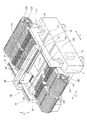
図1〜図3に示すように、本実施形態による表面実装機101は、プリント基板110(図2参照)に部品120(図2参照)を実装する装置である。なお、プリント基板110は、本発明の「基板」の一例である。図2に示すように、表面実装機101は、X方向に延びる一対の基板搬送コンベア10と、一対の基板搬送コンベア10の上方をXY方向に移動可能なヘッドユニット20とを備えている。また、基板搬送コンベア10およびヘッドユニット20は、基台1上に設置されている。基台1の一対の基板搬送コンベア10の両側には、図2および図3に示すように、それぞれ、片側24箇所ずつ、合計48箇所のテープフィーダ装着部2(図3参照)がX方向に並ぶように設けられている。複数のテープフィーダ装着部2には、それぞれ、部品120(図2参照)を供給するための複数のテープフィーダ121が着脱可能に配置されている。なお、テープフィーダ121は、本発明の「部品供給部」の一例である。また、ヘッドユニット20は、テープフィーダ121から部品120を取得するとともに、基板搬送コンベア10上のプリント基板110に部品120を実装する機能を有する。以下、表面実装機の管理システム100の具体的な構造を説明する。
As shown in FIGS. 1 to 3, the
一対の基板搬送コンベア10は、プリント基板110をX方向に搬送するとともに、所定の実装作業位置でプリント基板110を停止させ、保持させることが可能なように構成されている。
A pair of board |
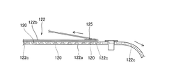
テープフィーダ121は、図4に示すように、複数の部品120が収容されたテープ122が巻き回されたリール123を保持している。なお、テープ122は、本発明の「部品収容部材」および「第2部品収容テープ」の一例である。このテープフィーダ121は、リール123を回転させることにより部品120を収容するテープ122を送り出すことによって、テープフィーダ121の先端から部品120を供給するように構成されている。なお、部品120は、IC、トランジスタ、コンデンサなどの小型の電子部品である。また、リール123には、テープ122に収容されている部品の情報を読み出し可能なバーコード124が貼り付けられている。このバーコード124の情報は、後述するPC(パーソナルコンピュータ)102に予め入力されている。なお、バーコード124は、本発明の「所定の識別コード」の一例である。
As shown in FIG. 4, the
ここで、本実施形態では、図5に示すように、テープ122は、部品120が収容されている紙製または樹脂製のキャリアテープ122aと、キャリアテープ122aの上面を覆うように配置されているトップテープ122bとにより構成されている。キャリアテープ122aには、図5および図6に示すように、部品120を収納するための複数の部品収納部122cがテープ122の供給方向に沿ってそれぞれ略等間隔に設けられている。また、キャリアテープ122aの部品収納部122cの側方には、図6に示すように、複数の係合穴部122dがテープ122の供給方向に沿ってそれぞれ等間隔に形成されている。これら複数の係合穴部122dは、図示しないギア部材と噛合するように構成されており、図示しないギア部材が回転されるのに伴ってテープ122が供給されるように構成されている。
Here, in this embodiment, as shown in FIG. 5, the
また、トップテープ122bは、図4および図5に示すように、キャリアテープ122aと分離されるように構成されている。具体的には、テープフィーダ121には、キャリアテープ122aとトップテープ122bとを分離するための分岐部材125が設けられているとともに、キャリアテープ122aから分離されたトップテープ122bを回収するためのリール部材126が設けられている。このリール部材126は、テープ122が供給されるのに伴って回転されるように構成されており、キャリアテープ122aから分離されたトップテープ122bを自身に巻きつけるように回収する機能を有する。
The
また、ヘッドユニット20は、図3に示すように、X方向に延びるヘッドユニット支持部30に沿ってX方向に移動可能に構成されている。具体的には、ヘッドユニット支持部30は、ボールネジ軸31とボールネジ軸31を回転させるサーボモータ32とX方向のガイドレール(図示せず)とを有しているとともに、ヘッドユニット20は、ボールネジ軸31が螺合されるボールナット21を有している。ヘッドユニット20は、サーボモータ32によりボールネジ軸31が回転されることにより、ヘッドユニット支持部30に対してX方向に移動するように構成されている。また、ヘッドユニット支持部30は、基台1上に設けられたY方向に延びる一対の固定レール部40に沿ってY方向に移動可能に構成されている。具体的には、固定レール部40は、ヘッドユニット支持部30の両端部をY方向に移動可能に支持するガイドレール41と、Y方向に延びるボールネジ軸42(図4参照)と、ボールネジ軸42を回転させるサーボモータ43(図4参照)とを有しているとともに、ヘッドユニット支持部30には、ボールネジ軸42が螺合されるボールナット33(図4参照)が設けられている。ヘッドユニット支持部30は、サーボモータ43によりボールネジ軸42が回転されることによって、ガイドレール41に沿ってY方向に移動するように構成されている。このような構成により、ヘッドユニット20は、基台1上をXY方向に移動することが可能なように構成されている。
Further, as shown in FIG. 3, the
また、ヘッドユニット20には、図2に示すように、X方向に列状に配置された6本の吸着ノズル22が下方に突出するように設けられている。また、各々の吸着ノズル22は、負圧発生機(図示せず)によってその先端に負圧状態を発生させることが可能に構成されている。吸着ノズル22は、この負圧によって、テープフィーダ121から供給される部品120を先端に吸着および保持することが可能である。
As shown in FIG. 2, the
また、各々の吸着ノズル22は、図示しない機構(サーボモータなど)によって、ヘッドユニット20に対して上下方向(Z方向)に移動可能に構成されている。表面実装機101は、吸着ノズル22が上昇位置に位置した状態で部品120の搬送などを行うとともに、吸着ノズル22が下降位置に位置した状態で部品120のテープフィーダ121からの吸着およびプリント基板110への実装を行うように構成されている。また、吸着ノズル22は、吸着ノズル22自体がその軸を中心として回転可能に構成されている。これにより、表面実装機101では、部品120を搬送する途中に吸着ノズル22を回転させることにより、ノズルの先端に保持された部品120の姿勢(水平面内の向き)を調整することが可能である。
Each
また、基台1の両側のテープフィーダ装着部2(図3参照)には、図1に示すように、片側に2台ずつ、合計4台の台車50(テープフィーダ装着部2の片側に接続される台車50のみ図示)が接続されている。これら台車50は、それぞれ、12本のテープフィーダ121を保持可能に構成されているとともに、台車50がテープフィーダ装着部2に接続された際に、台車50に保持されているテープフィーダ121をテープフィーダ装着部2に容易に装着することが可能なように構成されている。また、各台車50には、それぞれ、テープ回収ボックス51が台車50と着脱可能に配置されている。テープ回収ボックス51は、吸着ノズル22に部品120を供給し終えたキャリアテープ122a(図5参照)を回収するために設けられている。
In addition, as shown in FIG. 1, a total of four carts 50 (connected to one side of the tape feeder mounting portion 2) are connected to the tape feeder mounting portions 2 (see FIG. 3) on both sides of the
また、基板搬送コンベア10、ヘッドユニット20および基台1は、筐体60に覆われている。この筐体60には、図1および図7に示すように、表面実装機101を操作した際の操作状態を表示する表示装置61が取り付けられているとともに、表面実装機101の操作状態を示す警告灯62が取り付けられている。なお、警告灯62は、本発明の「告知部」の一例であり、表示装置61は、本発明の「告知部」および「表示部」の一例である。また、筐体60の内部には、図7に示すように、実装制御処理部71が内蔵されている。この実装制御処理部71は、論理演算を実行するCPU、CPUを制御するプログラムなどを記憶するROM(Read Only Memory)および装置の動作中に種々のデータを一時的に記憶するRAM(Random Access Memory)などから構成されている。実装制御処理部71は、ROMに記憶されているプログラムに従って、各サーボモータなどを制御するように構成されている。
The
また、実装制御処理部71には、上記した表示装置61および警告灯62と、スピーカ63とが接続されている。なお、スピーカ63は、本発明の「告知部」の一例である。このスピーカ63は、表面実装機101の作動状態および操作状態が適切でない場合に警告音を発する機能を有する。また、実装制御処理部71には、バーコード読取装置64と入力部65とがさらに接続されている。バーコード読取装置64は、上記したリール123に貼り付けられているバーコード124(図3参照)、および、各テープフィーダ装着部2(図2参照)に対応するバーコード3(図1参照)などを読み取る機能を有する。入力部65は、作業者が表面実装機101の操作を行うための情報を入力するために設けられている。
The mounting
また、表面実装機101は、図1および図7に示すように、PC(パーソナルコンピュータ)102と接続されている。具体的には、PC102には、後述する生産前の段取りを行う際の情報の処理などを行う演算処理部81が内蔵されており、PC102の演算処理部81は、表面実装機101の実装制御処理部71と接続されている。PC102の演算処理部81は、論理演算を実行するCPUにより構成されている。なお、演算処理部81は、本発明の「制御部」の一例である。また、演算処理部81には、ROMからなる記憶部82が接続されており、記憶部82には、生産プログラム83と、バーコード3およびバーコード124などの照合コード84とが記憶されている。生産プログラム83には、後述する生産前の段取りを行う際の情報が整理されている部品配置表83a(図8参照)、生産予定表83b(図9参照)および在庫部品表83c(図10参照)などが含まれている。なお、記憶部82は、本発明の「部品必要数記憶部」、「部品残数記憶部」および「保管テープ情報記憶部」の一例である。
Further, the
また、PC102の演算処理部81には、表示装置85、入力操作装置86およびバーコード読取装置87が接続されている。なお、表示装置85は、本発明の「告知部」および「表示部」の一例である。表示装置85は、後述する生産前の準備を行う際の操作画面などを表示する機能を有する。入力操作装置86は、作業者が生産前の準備時(前段取り時)などに操作を行うための情報を入力するために設けられている。バーコード読取装置87は、テープフィーダ121のリール123に貼り付けられているバーコード124の情報を読み取る機能を有する。なお、表示装置85、表面実装機101およびPC102によって、表面実装機の管理システム100が構成されている。また、表面実装機の管理システム100は、本発明の「表面実装機の部品供給管理システム」の一例である。
In addition, a
次に、本発明の一実施形態による表面実装機の管理システム100における生産前の準備時における各生産管理表について詳細に説明する。
Next, each production management table at the time of preparation before production in the surface
図8は、本発明の一実施形態による表面実装機の管理システムの部品配置表を示した図である。まず、本発明の一実施形態による表面実装機の管理システム100の部品配置表83aについて詳細に説明する。なお、図8の部品配置表83aは、本実施形態では、一例として、100枚のプリント基板110に実装を行う基板名Dの生産の部品配置表を示している。
FIG. 8 is a diagram showing a component arrangement table of the surface mounter management system according to the embodiment of the present invention. First, the component arrangement table 83a of the surface
図8に示すように、PC102の表示装置85に表示されている部品配置表83aは、テープ122に収容された部品120がプリント基板110に実装される前の生産前の準備時(前段取り時)において生産に使用される部品120(リール123)などの情報を表わした表である。この部品120(リール123に巻きつけられたテープ122)などの情報は、バーコード読取装置87などによりリール123のバーコード124が読み取られることによって、各生産管理表に書き込まれている。マシンIDは、プリント基板110を生産する表面実装機のID(識別情報)のことである。この部品配置表83aのマシンIDの欄には、本実施形態の表面実装機101のマシンIDがY1であると表示されている。部品配置位置の欄は、リール123を保持するテープフィーダ121がテープフィーダ装着部2のいずれの部分に配置されているかを示している。具体的には、作業者がバーコード読取装置64などによりテープフィーダ121のリール123に貼り付けられているバーコード124をスキャンするとともに所定のテープフィーダ装着部2に対応するバーコード3(図1参照)をスキャンした場合に、部品配置位置の欄に所定のテープフィーダ装着部2に対応する部品配置位置番号が表示される。また、部品名の欄には、各番号に対応するリール123に巻きつけられたテープ122に収容された部品120の名称が表示されている。たとえば、部品配置位置番号が1の行のリール123の部品名の欄には、部品名「AAA」が表示されている。
As shown in FIG. 8, the component arrangement table 83 a displayed on the
ここで、本実施形態では、1枚当り使用数の欄には、実装を行う(生産を予定している)複数のプリント基板110のうち1枚当りに配置される部品数が表示されている。たとえば、部品配置位置番号が1の行の1枚当り使用数の欄には、プリント基板110の1枚当り使用数「1」が表示されている。必要数の欄には、生産を予定しているプリント基板110の枚数にプリント基板110の1枚当りに使用される部品数を乗じた値が表示されている。たとえば、部品配置位置番号が1の行のリール123の必要数の欄には、生産を予定しているプリント基板110の枚数「100」にプリント基板110の1枚当りに使用される部品数「1」を乗じた値である「100」が表示されている。なお、必要数は、本発明の「部品必要数」の一例である。
Here, in the present embodiment, the number of parts used per one of a plurality of printed
また、本実施形態では、スプライシング済み数の欄には、プリント基板110の生産前の準備時におけるリール123に巻きつけられたテープ122に収容された部品120の部品残数が表示されている。たとえば、部品配置位置番号が1の行のリール123のスプライシング済み数の欄には、リール123に巻きつけられている部品名「AAA」(部品ID「111XXX」)の部品数「15」とリール123に巻きつけられているの部品名「AAA」(部品ID「111ZZZ」)の部品数「20」とを加算した値「35」が表示されている。なお、スプライシングとは、図6に示すように、部品残数が少なくなったテープ122に対して新しいテープ122を所定の接続部材127を用いて継ぎ足すように接続する作業者により行われる作業のことである。この場合、部品残数が少なくなったテープ122は、本発明の「部品収容部材」および「第2部品収容テープ」の一例であり、新しいテープ122は、本発明の「第1部品収容テープ」の一例である。また、スプライシング済み数は、本発明の「部品残数」の一例である。
Further, in the present embodiment, the number of remaining parts of the
また、本実施形態では、図8に示すように、不足数の欄には、記憶部82に記憶された必要数から記憶部82に記憶されたスプライシング済み数を、演算処理部81により減じられた値が表示されている。つまり、不足数の欄には、プリント基板110の生産に必要な部品120の必要数からリール123に巻きつけられたテープ122に収容された部品120の部品残数を減じた値が表示されている。たとえば、部品配置位置番号が1の行のリール123の不足数の欄には、プリント基板110の生産に必要な部品120の必要数「100」からリール123に巻きつけられたテープ122に収容された部品120の部品残数(スプライシング済み数)「35」を減じた値である「65」が表示されている。これにより、プリント基板110の生産前の準備時に、追加するべき生産に必要な部品120の数を把握することが可能となる。
Further, in the present embodiment, as shown in FIG. 8, the spliced number stored in the
ここで、本実施形態では、表面実装機の管理システム100は、不足数の欄に1以上の値が表示された場合に、警告が告知されるように構成されている。具体的には、リール123に巻きつけられたテープ122に収容された部品120の部品残数がプリント基板110の生産に必要な部品120の必要数よりも少ない場合に、演算処理部81によって、表示装置61および85と、警告灯62と、スピーカ63とが警告が告知されるように制御される。
Here, in the present embodiment, the surface
また、スプライシング済み部品IDの欄には、後述するリール123に巻きつけられたテープ122に収容された部品120の部品IDが表示されている。たとえば、部品配置位置番号が1の行のリール123のスプライシング済み部品IDの欄には、部品ID「111XXX」と部品ID「111ZZZ」が表示されている。
In the spliced component ID column, the component ID of the
また、本実施形態では、スプライシング候補部品の欄には、図10の在庫部品表83cに表示されており(記憶部82に記憶されており)、かつ、表面実装機101に装着されたテープフィーダ121とは異なる場所に設けられたリール123のうち、表面実装機101に装着されたテープフィーダ121に保持されたリール123に巻きつけられた(スプライシング済みの)テープ122に接続するのに適したテープ122が表示されている。たとえば、部品配置位置番号が1の行のリール123のスプライシング候補部品の欄には、部品ID「111RRR」が表示されている。この場合、表面実装機101に装着されたテープフィーダ121に保持されたリール123に巻きつけられたテープ122は、本発明の「部品収容部材」および「第2部品収容テープ」の一例であり、リール123に巻きつけられたテープ122に接続するのに適したリール123のテープ122は、本発明の「第1部品収容テープ」の一例である。この表面実装機101に装着されたテープフィーダ121に保持されたリール123に巻きつけられたテープ122に接続するのに適したテープ122は、スプライシング済み数(部品残数)が必要数(部品必要数)よりも少ない場合に、図10の在庫部品表83c(記憶部82)に記憶され、かつ、表面実装機101に装着されたテープフィーダ121とは異なる場所に設けられた複数のリール123から、演算処理部81により選択される。
In the present embodiment, the splicing candidate parts column displays the inventory parts table 83c in FIG. 10 (stored in the storage unit 82) and the tape feeder mounted on the
また、生産可能判定状態の欄には、スプライシング済み数(部品残数)とスプライシング候補部品のリール123に巻きつけられたテープ122に収容されている部品数とが加算された値が、必要数(部品必要数)以上であるか否かの判定が表示されている。たとえば、部品配置位置番号が1のリール123のスプライシング候補部品の欄において、スプライシング済み数「35」とスプライシング候補部品のテープ122に収容されている部品数「80」とが加算された部品数「115」は、必要数「100」の115%の部品数であるので、部品配置位置番号が1のリール123のスプライシング候補部品の欄には、生産可能判定状態「O.K.」が表示されている。
In addition, in the column of the production possibility determination state, a value obtained by adding the number of spliced parts (the number of remaining parts) and the number of parts accommodated in the
図9は、本発明の一実施形態による表面実装機の管理システムの生産予定表を示した図である。次に、本発明の一実施形態による表面実装機の管理システム100の生産予定表83bについて詳細に説明する。
FIG. 9 is a diagram showing a production schedule of the surface mounter management system according to the embodiment of the present invention. Next, the
図9に示すように、PC102の表示装置85に表示されている生産予定表83bは、表示装置85に複数の種類のプリント基板110毎の生産枚数を表示するための表である。基板名は、生産を行う各種のプリント基板110の各々の基板名である。なお、基板Dは、図8の部品配置表83aにおいて生産を予定しているプリント基板110を表わしている。つまり、部品配置表83aと生産予定表83bとは関連付けされている。また、生産枚数の欄には、生産を予定しているプリント基板110の枚数が各種のプリント基板110毎に表示されている。たとえば、基板Dでは、100枚の生産枚数が予定されていることが表示されている。また、段取り状態の欄には、生産を予定しているプリント基板110毎の段取り状態が表示されている。この段取り状態とは、直ちにプリント基板110の生産が行うことが可能か否かを表わした状態であり、段取り状態の欄に「完了」と表示されている場合、直ちにプリント基板110の生産が行うことが可能である。また、段取り状態の欄に「未段取り」と表示されている場合、プリント基板110の生産を行う準備をする必要がある。
As shown in FIG. 9, the production schedule table 83 b displayed on the
図10は、本発明の一実施形態による表面実装機の管理システムの在庫部品表を示した図である。次に、本発明の一実施形態による表面実装機の管理システム100の在庫部品表83cについて詳細に説明する。
FIG. 10 is a view showing an inventory parts table of the surface mounter management system according to the embodiment of the present invention. Next, the inventory parts table 83c of the surface
図10に示すように、PC102の表示装置85に表示されている在庫部品表83cは、記憶部82に読み込まれた在庫部品の情報を表示するための表である。部品IDは、バーコード読取装置64または87によりリール123に貼り付けられているバーコード124が読み込まれた際に記憶部82に記憶された各リール123毎のIDのことである。たとえば、図10の部品在庫表83cには、部品ID「111XXX」、部品ID「111ZZZ」、部品ID「111RRR」および部品ID「111PPP」などが登録されている。なお、部品IDは、スプライシングを行った際に、2つのリール123にそれぞれ巻きつけられているテープ122を互いに接続した後、接続されたテープを1つのリール123に巻きつけるため、2つ以上の部品IDを有するリール123が存在する場合がある。具体的には、部品配置位置「1」(図8参照)のテープフィーダ121に保持されたリール123は、部品ID「111XXX」および部品ID「111ZZZ」の2つの部品IDを有している。また、部品名の欄には、各部品IDに対応するリール123に巻きつけられたテープ122に収容された部品120の名称が表示されている。たとえば、部品ID「111XXX」における部品名の欄には、部品名「AAA」が表示されている。
As shown in FIG. 10, an inventory parts table 83 c displayed on the
また、残数の欄には、各部品IDに対応するリール123に巻きつけられたテープ122に収容されている部品120の残数が表示されている。たとえば、部品ID「111XXX」における残数の欄には、残数「15」が表示されている。
In the remaining number column, the remaining number of
また、最初の使用日の欄には、各部品IDに対応するリール123が最初に部品在庫表83cに登録された日が表示されている。つまり、最初の使用日とは、バーコード読取装置64または87によりリール123に貼り付けられているバーコード124が読み込まれた最初の日のことである。たとえば、部品ID「111XXX」に対応するリール123は、バーコード124が「2007年8月12日」に初めて読み込まれたリール123であることを意味している。
In the first use date column, the date when the
また、在庫期間の欄には、各部品120毎の使用可能期間が表示されている。具体的には、在庫期間とは、最初の使用日から数えて使用可能な期間を表わしている。たとえば、図10の在庫部品表83cには、部品ID「111XXX」に対応するリール123の部品「AAA」は2007年8月12日から90日後の2007年11月9日までに生産に使用する必要があることが表わされている。
In the inventory period column, a usable period for each
また、在庫場所の欄には、各部品IDに対応するリール123が収納または配置されている場所が表示されている。たとえば、部品ID「111XXX」に対応するリール123は、マシンID「Y1」の部品配置位置「1」に配置されていることが表わされており、部品ID「111ZZZ」に対応するテープ122も、マシンID「Y1」の部品配置位置「1」に配置されていることが表わされている。また、部品ID「111RRR」に対応するリール123は、図示しない部品棚「1」に収納されていることが表わされている。
Further, in the inventory location column, the location where the
図11は、本発明の一実施形態による表面実装機の管理システムの操作画面を示した図である。次に、本発明の一実施形態による表面実装機の管理システム100の生産前の準備時に表示装置85に表示される操作画面90について詳細に説明する。
FIG. 11 is a diagram showing an operation screen of the surface mounter management system according to the embodiment of the present invention. Next, the
図11に示すように、操作画面90は、生産前の準備時にPC102の表示装置85に表示される操作画面である。本実施形態による表面実装機の管理システム100の操作画面90は、作業者に対して行うべき作業を文章により案内するナビゲーション領域91と、部品配置表83a、生産予定表83bおよび在庫部品表83cなどの必要な生産管理表を表示する管理表表示領域92と、表面実装機101に装着されているテープフィーダ121に保持されたリール123に巻きつけられたテープ122に収容されている部品120の部品残数などを図示する図示領域93とにより主に構成されている。
As shown in FIG. 11, the
ナビゲーション領域91には、作業者にスプライシングを行わせる際の手順などを案内する文章が表示される。たとえば、図11の操作画面90の場合、ナビゲーション領域91には、部品配置位置番号「1」のテープフィーダ装着部2に装着されているテープフィーダ121に保持されたリール123のテープ122(部品ID「111XXX」および部品ID「111ZZZ」)とスプライシング候補部品であるリール123のテープ122(部品ID「111RRR」)とをスプライシングするように作業者に促す文章が表示されている。
In the
管理表表示領域92には、ナビゲーション領域91に表示されたナビゲーションの内容に対応する生産管理表が表示される。たとえば、図11の操作画面90の場合、管理表表示領域92には、スプライシングを行うべき部品配置位置番号「1」のテープフィーダ装着部2に装着されているテープフィーダ121に保持されたリール123に巻きつけられたテープ122(部品ID「111XXX」および部品ID「111ZZZ」)の状態が示された部品配置表83aが表示されている。なお、この場合、上記したリール123に巻きつけられたテープ122に収容された部品120の部品残数がプリント基板110の生産に必要な部品120の必要数よりも少ない場合であるので、スプライシングを行うべき部品配置位置番号「1」の行、部品配置位置番号「3」の行および部品配置位置番号「4」の行は、作業者に警告するためにその背景が赤色で点滅されている。
In the management
また、図示領域93は、テープフィーダ装着部2に装着される4台の台車50が図示される台車表示部93aと、各テープフィーダ装着部2毎の部品残数などがグラフとして図示されるグラフ表示部93bと、グラフ表示部93bに表示されるグラフの表示形式を変更可能なチェックボックス部93cとにより主に構成されている。
The illustrated
台車表示部93aは、4台の台車50のうちグラフ表示部93bに表示されている台車50を表示している。たとえば、図11の操作画面90のグラフ表示部93bには、「台車番号8」が表示されているので、台車表示部93aには、「台車番号8」の台車を表わす「8」のボックスが点滅される。
The
チェックボックス部93cは、グラフ表示部93bに表示されるグラフの表示形式を変更可能な排他的チェックボックスにより構成されている。このチェックボックス部93cの「残数/必要部品数」とは、チェックされることにより、生産を行うプリント基板110に必要な必要部品数に対するテープ122に収容されている部品120の残数の割合をグラフ表示部93bに表示する機能を有する。
The
また、チェックボックス部93cの「残り数/入り数」とは、チェックされることにより、テープ122に最初に収容されている部品数に対するテープ122に現在収容されている部品120の残数の割合をグラフ表示部93bに表示する機能を有する。
Further, the “remaining number / entry number” of the
また、チェックボックス部93cの「生産可能枚数」とは、チェックされることにより、生産を行いたいプリント基板110を何枚生産することが可能であるのかをグラフ表示部93bに表示する機能を有する。この「生産可能枚数」を表示することによって、現在スプライシングされている部品120を用いることによりプリント基板110を何枚生産することが可能かを作業者に認識させることが可能となる。これにより、目的の生産を行うための部品120の補充を行う数の目安を作業者に認識させることが可能となる。
The “production possible number” of the
また、チェックボックス部93cの「生産可能予想時間」とは、チェックされることにより、現在スプライシングされている部品120を用いることによるプリント基板110の生産終了予想時間をグラフ表示部93bに表示する機能を有する。この「生産可能予想時間」を表示することによって、次に補充を行う時間を作業者に把握させることが可能となる。
The “estimated production time” of the
また、チェックボックス部93cの「共通段取り必要量」とは、チェックされることにより、複数の種類のプリント基板110において共通に用いられる部品120の必要数に対するテープ122に収容されている部品120の残数の割合をグラフ表示部93bに表示する機能を有する。
In addition, the “common setup requirement” in the
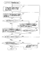
図12および図13は、本発明の一実施形態による表面実装機の管理システムの演算処理部がスプライシングするのに適切なテープを作業者に案内する際の制御を説明するためのフローチャートである。次に、本実施形態の表面実装機の管理システム100による演算処理部81がスプライシングするのに適切なテープを作業者に案内する際の制御動作について説明する。
FIG. 12 and FIG. 13 are flowcharts for explaining the control when the arithmetic processing unit of the surface mounter management system according to an embodiment of the present invention guides an appropriate tape to the worker for splicing. Next, the control operation when the
まず、図12に示すように、ステップS1において、演算処理部81により、生産予定表83bの段取り状態(図9参照)の欄が未段取りであるプリント基板が自動選択されるとともに、選択されたプリント基板が生産を予定するプリント基板であると認識され、表示装置85に部品配置表83aが表示される。そして、ステップS2において、生産を予定するプリント基板の1枚当り使用数(図8参照)と生産枚数(図9参照)とにより、プリント基板の生産に使用される部品の必要数(図8参照)が算出される。具体的には、プリント基板の1枚当り使用数(図8参照)に生産枚数(図9参照)を乗ずることにより、使用数(図8参照)が算出される。
First, as shown in FIG. 12, in step S <b> 1, the
そして、ステップS3において、演算処理部81により、スプライシング済み数(図8参照)が算出される。具体的には、表面実装機101の所定の番号(図8参照)のテープフィーダ装着部2に配置されているテープフィーダ121のリール123の部品120の部品IDの残数(図10参照)が合計される。そして、ステップS4において、演算処理部81により、プリント基板の生産を行う際に必要とする部品の不足数(図8参照)が算出される。具体的には、必要数(図8参照)からスプライシング済み数(図8参照)が減算される。このとき、1以上の不足数が算出された場合、演算処理部81により、警告灯62、スピーカ63、表示装置61および85は、警告を告知するように制御される。
In step S3, the
その後、ステップS5において、不足数(図8参照)が1以上であると記録されている部品配置位置番号のテープフィーダ121に保持されたリール123のテープ122に、スプライシングするのに適したリール123のスプライシング候補部品ID(図8参照)が部品在庫表83cより抽出され、ステップS6に進む。そして、ステップS6において、抽出されたスプライシング候補部品ID(図8参照)と生産可能判定状態(図8参照)とを表示装置85に表示する。これにより、作業者に対してスプライシングするのに適した具体的なリール123を認識させることが可能となるので、作業者に対してスプライシング作業を行う動機付けを与えることが可能となる。
Thereafter, in step S5, the
そして、ステップS7において、演算処理部81により、部品配置位置番号のテープフィーダ121に保持されたリール123(表面実装機101に配置されているリール123)に対応するバーコード124と、スプライシングするのに適したリール123に対応するバーコード124との両方が作業者によりスキャンされたか否かが判断される。つまり、部品配置位置番号のリール123(表面実装機101に配置されているリール123)に対応する部品IDと、スプライシングするのに適したリール123に対応する部品IDとの両方が認識されたか否かが判断される。そして、ステップS7において、部品配置位置番号のリール123に対応するバーコード124と、スプライシングするのに適したリール123に対応するバーコード124との両方が作業者によりスキャンされていないと判断された場合には、ステップS7の動作が繰り返される。また、ステップS7において、部品配置位置番号のリール123に対応するバーコード124と、スプライシングするのに適したリール123に対応するバーコード124との両方が作業者によりスキャンされたと判断された場合には、ステップS8に進む。また、本実施形態では、ステップS7において、部品配置位置番号のリール123に対応するバーコード124と、スプライシングするのに適したリール123に対応するバーコード124との両方が作業者によりスキャンされたと判断された場合には、演算処理部81は、作業者により表面実装機101に配置されているテープフィーダ121に保持されたリール123のテープ122とスプライシングするのに適したリール123のテープ122とがスプライシングされたものと認識する。
In step S7, the
その後、ステップS8において、演算処理部81により、部品配置表83aのスプライシング候補部品の部品IDと作業者によりバーコードスキャンされたリール123の部品IDとが一致しているか否かが判断される。そして、ステップS8において、部品配置表83aのスプライシング候補部品の部品IDと作業者によりバーコードスキャンされたリール123の部品IDとが一致していないと判断された場合には、ステップS9に進み、演算処理部81により表示装置85にエラーが表示された後にステップS6に戻る。また、ステップS8において、部品配置表83aのスプライシング候補部品の部品IDと作業者によりバーコードスキャンされたリール123の部品IDとが一致していると判断された場合には、ステップS10に進む。
Thereafter, in step S8, the
その後、ステップS10において、演算処理部81により、部品配置表83aに表示されている全てのスプライシング候補部品IDについて上記ステップS6〜ステップS8の処理が行われたか否かが判断される。そして、ステップS10において、部品配置表83aに表示されている全てのスプライシング候補部品IDについて上記ステップS6〜ステップS8の処理が行われていないと判断された場合には、ステップS6に戻る。また、ステップS10において、部品配置表83aに表示されている全てのスプライシング候補部品IDについて上記ステップS6〜ステップS8の処理が行われたと判断された場合には、スプライシングするのに適切なテープを作業者に案内する際の制御動作が終了される。
Thereafter, in step S10, the
次に、不足数が1以上のスプライシング候補部品IDを在庫部品表より抽出する際の制御動作について説明する。 Next, the control operation when extracting the splicing candidate part ID having a shortage number of 1 or more from the inventory parts table will be described.
図13に示すように、ステップS11において、演算処理部81により、在庫部品表83cに登録された複数のリール123(テープ122)のうち登録された時の最も古いリール123から順に、表面実装機101に配置されているテープフィーダ121に保持されたリール123のテープ122に接続(スプライシング)するのに適したリール123の部品IDが抽出される。そして、ステップS12において、演算処理部81により、スプライシング済み数(図8参照)と登録された時の最も古い抽出されたリール123に巻きつけられたテープ122に収容されている部品120の合計数とに基づいて生産可能判定状態(図8参照)が仮計算される。
As shown in FIG. 13, in step S11, the surface mounter is sequentially operated by the
そして、ステップS13において、演算処理部81により、仮計算された生産可能判定状態は100%以上(O.K.)であるか否かが判断される。そして、ステップS13において、仮計算された生産可能判定状態は100%以上(O.K.)であると判断された場合には、ステップS14に進む。そして、ステップS14において、抽出されたリール123(部品ID)がスプライシング候補部品(図8参照)として記憶部82に記憶される。なお、このステップS14において、前に記憶したスプライシング候補部品(部品ID)があれば、残数(図10参照)が小さいスプライシング候補部品の順で記憶部82に記憶され、ステップS15に進む。
In step S13, the
また、ステップS13において、仮計算された生産可能判定状態は100%以上(O.K.)でないと判断された場合には、ステップS16に進む。そして、ステップS16において、抽出されたリール123(部品ID)がスプライシング候補部品(図8参照)として記憶部82に記憶される。なお、このステップS16において、前に記憶したスプライシング候補部品(部品ID)があれば、前に記憶したスプライシング候補部品(部品ID)と共に抽出されたスプライシング候補部品が記憶部82に記憶され、ステップS17に進む。その後、ステップS17において、演算処理部81により、記憶部82に記憶されたスプライシング候補部品の合計に基づいて、生産可能判定状態は100%以上(O.K.)であるか否かが計算されるとともに判断される。そして、ステップS17において、生産可能判定状態は100%以上(O.K.)であると判断された場合には、ステップS15に進む。また、ステップS17において、生産可能判定状態は100%以上(O.K.)でないと判断された場合には、ステップS12に戻る。
If it is determined in step S13 that the provisionally calculated production availability determination state is not 100% or more (OK), the process proceeds to step S16. In step S16, the extracted reel 123 (part ID) is stored in the
その後、ステップS15において、部品配置表83aにおいて次に抽出された部品名(図8参照)があるか否かが判断される。そして、ステップS15において、部品配置表83aにおいて次に抽出された部品名(図8参照)があると判断された場合には、ステップS11に戻り、次に抽出された部品名について、ステップS11の処理が行われる。また、ステップS15において、部品配置表83aにおいて次に抽出された部品名(図8参照)がないと判断された場合には、ステップS18に進む。 Thereafter, in step S15, it is determined whether or not there is a component name (see FIG. 8) extracted next in the component arrangement table 83a. If it is determined in step S15 that there is a part name (see FIG. 8) extracted next in the part arrangement table 83a, the process returns to step S11, and the next extracted part name is determined in step S11. Processing is performed. If it is determined in step S15 that there is no part name (see FIG. 8) extracted next in the part arrangement table 83a, the process proceeds to step S18.
その後、ステップS18において、演算処理部81により、部品配置表83aの各部品配置位置番号の行において生産可能判定状態(図8参照)が100%以下の部品があるか否かが判断される。そして、ステップS18において、部品配置表83aの各部品配置位置番号の行において生産可能判定状態(図8参照)が100%以下の部品があると判断された場合には、ステップS19に進む。そして、ステップS19において、演算処理部81により、プリント基板110の生産中に部品の補充(スプライシング)が必要になる旨が表示装置85に表示され、不足数が1以上のスプライシング候補部品IDを在庫部品表より抽出する際の制御動作が終了される。また、ステップS18において、部品配置表83aの各部品配置位置番号の行において生産可能判定状態(図8参照)が100%以下の部品がないと判断された場合には、不足数が1以上のスプライシング候補部品IDを在庫部品表より抽出する際の制御動作が終了される。
Thereafter, in step S18, the
本実施形態では、上記のように、テープ122に収容された部品120がプリント基板110に実装される前の生産準備時において、テープフィーダ装着部2に装着されたテープフィーダ121に保持されたリール123に巻きつけられたテープ122に収容されている部品120の部品残数(スプライシング済み数)がプリント基板110の生産に必要な部品120の部品必要数よりも少ない場合に、警告を発する警告灯62と、スピーカ63と、表示装置61および85とを設けることによって、プリント基板110の生産を行う前に、生産に必要な部品120が不足していることを作業者に知らせることができるので、作業者に対して、テープフィーダ装着部2に装着されたテープフィーダ121に保持されたリール123に巻きつけられたテープ122に部品(別のテープ122)を補充する(スプライシングする)作業を行うように促すことができる。これにより、作業者がテープフィーダ装着部2に装着されたテープフィーダ121に保持されたリール123に巻きつけられたテープ122に部品(別のテープ122)を補充した場合に、生産中にプリント基板110に実装される部品が不足するのを抑制することができるので、テープフィーダ装着部2に装着されたテープフィーダ121に保持されたリール123に巻きつけられたテープ122に収容された部品120が実装されないままプリント基板110の生産が行われるのを抑制することができる。その結果、部品120が実装されていないプリント基板110に対して、部品120を実装する作業を別途行う必要がなくなるので、プリント基板110の生産が完了するのが遅くなるのを抑制することができる。
In the present embodiment, as described above, the reel held by the
また、本実施形態では、上記のように、プリント基板110の生産予定量に基づいてテープフィーダ121からプリント基板110に実装される際に必要とされる部品120の部品必要数、および、テープフィーダ装着部2に装着されたテープフィーダ121に保持されたリール123に巻きつけられたテープ122に収容された部品120の部品残数(スプライシング済み数)を記憶する記憶部82を設けることによって、記憶部82により、容易に、テープフィーダ121からプリント基板110に実装される際に必要とされる部品120の部品必要数、および、テープフィーダ121からプリント基板110に実装される際に必要とされる部品120に収容された部品120の部品残数(スプライシング済み数)を記憶することができる。また、テープフィーダ121からプリント基板110に実装される際に必要とされるテープ122に収容された部品120がプリント基板110に実装される前の生産準備時において、部品120の部品残数(スプライシング済み数)が部品120の部品必要数よりも少ない場合に、警告を発するように警告灯62とスピーカ63と表示装置61および85とを制御する演算処理部81を設けることによって、演算処理部81により、部品必要数および部品残数(スプライシング済み数)に基づいて生産に必要な部品120が不足しているか否かを算出することができる。
Further, in the present embodiment, as described above, the necessary number of
また、本実施形態では、上記のように、演算処理部81を、テープフィーダ装着部2に装着されたテープフィーダ121に保持されたリール123のテープ122に接続するのに適したリール123(テープ122)を表示装置85に表示するように構成することによって、作業者は、テープフィーダ装着部2に装着されたテープフィーダ121に保持されたリール123のテープ122に接続するのに適したリール123(テープ122)を視覚的に認識することができるので、作業者がテープフィーダ装着部2に装着されたテープフィーダ121に保持されたリール123のテープ122に接続するのに適さないリール123(テープ122)をテープフィーダ装着部2に装着されたテープフィーダ121に保持されたリール123のテープ122に接続するのを抑制することができる。
In the present embodiment, as described above, the
また、本実施形態では、上記のように、演算処理部81を、在庫部品表83cに登録された複数のリール123のうち登録された時の最も古いリール123を、表面実装機101に配置されているテープフィーダ121に保持されたリール123のテープ122に接続(スプライシング)するのに適したリール123(部品ID)として選択するように構成することによって、複数のリール123のうち登録された時の最も古いリール123のテープ122からプリント基板110の生産に使用されるので、古いリール123が残るのを抑制することができる。
In the present embodiment, as described above, the
また、本実施形態では、上記のように、演算処理部81を、部品配置位置番号のリール123(表面実装機101に配置されているリール123)に対応する部品IDおよびスプライシングするのに適したリール123に対応する部品IDの両方が読み込まれた際に、スプライシングするのに適したリール123のテープ122が表面実装機101に配置されているテープフィーダ121に保持されたリール123のテープ122に接続されたと認識するように構成することによって、作業者によりスプライシングするのに適したリール123のテープ122が表面実装機101に配置されているテープフィーダ121に保持されたリール123のテープ122に接続された際に、演算処理部81にスプライシングするのに適したリール123のテープ122と表面実装機101に配置されているテープフィーダ121に保持されたリール123のテープ122とが接続されたことを認識させるために作業者に別途作業を行わせるのを抑制することができる。これにより、作業者に対する作業負担が増加するのを抑制することができる。
Further, in the present embodiment, as described above, the
なお、今回開示された実施形態は、すべての点で例示であって制限的なものではないと考えられるべきである。本発明の範囲は、上記した実施形態の説明ではなく特許請求の範囲によって示され、さらに特許請求の範囲と均等の意味および範囲内でのすべての変更が含まれる。 The embodiment disclosed this time should be considered as illustrative in all points and not restrictive. The scope of the present invention is shown not by the above description of the embodiments but by the scope of claims for patent, and further includes all modifications within the meaning and scope equivalent to the scope of claims for patent.
たとえば、上記実施形態では、部品配置表、生産予定表および在庫部品表を表示装置85に表示する例について示したが、本発明はこれに限らず、部品配置表、生産予定表および在庫部品表を表示装置61に表示するようにしてもよい。
For example, in the above-described embodiment, an example in which the parts arrangement table, the production schedule table, and the inventory parts table are displayed on the
また、上記実施形態では、演算処理部を、部品の部品残数がプリント基板の生産に必要な部品の必要数よりも少ない場合に、表示装置61および表示装置85の両方に警告を告知するように制御する例について示したが、本発明はこれに限らず、警告を表示装置61および表示装置85のいずれか一方に告知するようにしてもよい。
In the above-described embodiment, the arithmetic processing unit notifies the
また、上記実施形態では、スプライシングするのに適切なテープを作業者に案内する際の制御を、表面実装機の管理システムのPCの演算処理部により行われるように構成した例について示したが、本発明はこれに限らず、スプライシングするのに適切なテープを作業者に案内する際の制御を、表面実装機の実装制御処理部により行われるように構成してもよい。 In the above-described embodiment, an example has been described in which control when guiding a tape suitable for splicing to an operator is performed by an arithmetic processing unit of a PC of a surface mounter management system. The present invention is not limited to this, and control when guiding a tape suitable for splicing to an operator may be performed by the mounting control processing unit of the surface mounter.
また、上記実施形態では、在庫部品表に登録された複数のテープのうち登録された時の最も古いテープを、表面実装機に配置されているテープにスプライシングするのに適したリールの部品IDとして選択するように構成した例を示したが、本発明はこれに限らず、たとえば、在庫部品表に登録された複数のテープのうち部品残数が最も少ないテープのように、登録された時の最も古いテープ以外のテープを、表面実装機に配置されているテープにスプライシングするのに適したリールの部品IDとして選択するように構成してもよい。 Moreover, in the said embodiment, as the part ID of the reel suitable for splicing the oldest tape at the time of registration among the several tapes registered into the inventory parts table | surface to the tape currently arrange | positioned at the surface mounting machine. Although an example configured to select is shown, the present invention is not limited to this. For example, a tape having the smallest number of remaining parts among a plurality of tapes registered in the inventory parts table is registered. A tape other than the oldest tape may be selected as the reel part ID suitable for splicing to the tape placed on the surface mounter.
また、上記実施形態では、部品配置表、生産予定表および在庫部品表を、表示装置に別々の画面として表示した例について示したが、本発明はこれに限らず、部品配置表、生産予定表および在庫部品表を、表示装置に同じ画面状に表示するようにしてもよい。 In the above embodiment, an example in which the parts arrangement table, the production schedule table, and the inventory parts table are displayed as separate screens on the display device is shown. However, the present invention is not limited to this, and the component arrangement table, production schedule table is displayed. The inventory parts table may be displayed on the display device in the same screen.
また、上記実施形態では、必要数、スプライシング済み数および不足数を表示装置に表示した上で、スプライシング済み数が必要数よりも少ない場合に警告が告知される例について示したが、本発明はこれに限らず、必要数、スプライシング済み数および不足数を表示装置に表示することなく、スプライシング済み数が必要数よりも少ない場合に警告を発するようにしてもよい。 In the above embodiment, the necessary number, the spliced number, and the shortage number are displayed on the display device, and the warning is notified when the spliced number is smaller than the necessary number. The present invention is not limited to this, and a warning may be issued when the number of spliced is less than the necessary number without displaying the necessary number, the number of spliced and the insufficient number on the display device.
また、上記実施形態では、必要数およびスプライシング済み数を記憶部に記憶された状態で、不足数を計算するように演算処理部を構成した例について示したが、本発明はこれに限らず、必要数およびスプライシング済み数を記憶部に記憶させずに、不足数を計算するように演算処理部を構成してもよい。 In the above embodiment, the example in which the arithmetic processing unit is configured to calculate the deficient number in the state where the necessary number and the spliced number are stored in the storage unit is shown, but the present invention is not limited thereto, The arithmetic processing unit may be configured to calculate the shortage number without storing the necessary number and the spliced number in the storage unit.
また、上記実施形態では、本発明の部品収容部材の一例としてリールに巻きつけられたテープを示したが、本発明はこれに限らず、リールに巻きつけられたテープ以外の、たとえば、部品収容トレイおよびその他の部品収容部材についても適用可能である。 Moreover, in the said embodiment, although the tape wound around the reel was shown as an example of the component accommodating member of this invention, this invention is not restricted to this, For example, components accommodating other than the tape wound around the reel The present invention can also be applied to trays and other component housing members.
また、上記実施形態では、台車1台当たりに12本のテープフィーダを保持可能に構成した例について示したが、本発明はこれに限らず、台車を、1台当たりに12本より多いテープフィーダを保持可能に構成してもよいし、1台あたりに12本未満のテープフィーダを保持可能に構成してもよい。 Moreover, in the said embodiment, although the example comprised so that 12 tape feeders could be hold | maintained per trolley | bogie was shown, this invention is not limited to this, More than 12 tape feeders per trolley | bogie is shown. May be configured to be capable of holding, or may be configured to be capable of holding less than 12 tape feeders per unit.
また、上記実施形態では、バーコード読取装置を表面実装機に設けた例について示したが、本発明はこれに限らず、バーコード読取装置をPCに設けるようにしてもよい。また、バーコード読取装置を表面実装機およびPCの両方に設けるようにしてもよい。 Further, in the above-described embodiment, an example in which the barcode reading device is provided in the surface mounter has been described. However, the present invention is not limited thereto, and the barcode reading device may be provided in the PC. Further, the barcode reader may be provided in both the surface mounter and the PC.
また、上記実施形態では、バーコードを読み取るためのバーコード読取装置を設けた例ついて示したが、本発明はこれに限らず、たとえば、QRコードのような2次元コードを読み取るコード読取装置のような、バーコード読取装置以外のコードを読み取り可能なコード読取装置を設けるようにしてもよい。 In the above-described embodiment, an example in which a barcode reader for reading a barcode is provided has been described. However, the present invention is not limited to this, and for example, a code reader for reading a two-dimensional code such as a QR code. A code reading device that can read codes other than the bar code reading device may be provided.
1 基台
61、85 表示装置(告知部、表示部)
62 警告灯(告知部)
63 スピーカ(告知部)
81 演算処理部(制御部)
82 記憶部(部品必要数記憶部、部品残数記憶部、保管テープ情報記憶部)
100 表面実装機の管理システム(表面実装機の部品供給管理システム)
101 表面実装機(表面実装機の部品供給管理システム)
102 PC(表面実装機の部品供給管理システム)
110 プリント基板(基板)
120 部品
121 テープフィーダ(部品供給部)
122 テープ(部品収容部材、第1部品収容テープ、第2部品収容テープ)
1
62 Warning light (notification department)
63 Speaker (Notification Department)
81 Arithmetic processing part (control part)
82 storage unit (required component number storage unit, component remaining number storage unit, storage tape information storage unit)
100 Surface mounter management system (Surface mounter component supply management system)
101 Surface mounter (Surface mounter component supply management system)
102 PC (Surface mounter parts supply management system)
110 Printed circuit board (board)
120
122 tape (component housing member, first component housing tape, second component housing tape)
Claims (8)
前記部品収容部材に収容された前記部品が前記基板に実装される前の生産準備時において、前記部品収容部材に収容されている前記部品の部品残数が前記基板の生産に必要な前記部品の部品必要数よりも少ない場合に、警告を告知する告知部を備える、表面実装機の部品供給管理システム。 A component supply management system for a surface mounter including a component supply unit mounted with a component storage member in which a plurality of components for mounting on a substrate are stored,
At the time of production preparation before the component housed in the component housing member is mounted on the substrate, the number of remaining parts of the component housed in the component housing member is the number of parts necessary for the production of the substrate. A component supply management system for surface mounters that includes a notification unit that issues a warning when the required number of components is less.
前記部品収容部材に収容された前記部品の部品残数を記憶する部品残数記憶部と、
前記部品収容部材に収容された前記部品が前記基板に実装される前の生産準備時において、前記部品残数記憶部に記憶された前記部品の部品残数が前記部品必要数記憶部に記憶された前記部品の部品必要数よりも少ない場合に、警告を告知するように前記告知部を制御する制御部とを備える、請求項1に記載の表面実装機の部品供給管理システム。 A required component number storage unit that stores the required component number of the component that is required when mounted on the substrate from the component supply unit based on the planned production amount of the substrate;
A remaining component number storage unit for storing the remaining component number of the component accommodated in the component accommodating member;
At the time of production preparation before the component housed in the component housing member is mounted on the board, the remaining component number stored in the remaining component number storage unit is stored in the required component number storage unit. 2. The surface mounter component supply management system according to claim 1, further comprising a control unit that controls the notification unit so as to notify a warning when the number of components is smaller than a required number of components.
前記部品収容部材は、第2部品収容テープを含み、
前記制御部は、前記部品残数記憶部に記憶された前記部品の部品残数が前記部品必要数記憶部に記憶された前記部品の部品必要数よりも少ない場合に、前記第2部品収容テープに接続するのに適した前記第1部品収容テープを前記保管テープ情報記憶部に記憶された前記複数の第1部品収容テープから所定の優先順位を付けて選択する制御を行うように構成されている、請求項2に記載の表面実装機の部品供給管理システム。 A storage tape information storage unit that stores information on a plurality of first component housing tapes provided at different locations from the component supply unit of the surface mounter;
The component housing member includes a second component housing tape,
When the remaining number of parts stored in the remaining part number storage unit is smaller than the required number of parts stored in the required part number storage unit, the control unit is configured to store the second component storage tape. The first component storage tape suitable for connection to the storage tape information is stored in the storage tape information storage unit, and is controlled to select the first component storage tape with a predetermined priority. The component supply management system for a surface mounter according to claim 2.
前記制御部は、前記第2部品収容テープに接続するのに適した第1部品収容テープを前記表示部に表示するように構成されている、請求項3に記載の表面実装機の部品供給管理システム。 A display unit connected to the control unit;
4. The component supply management of the surface mounter according to claim 3, wherein the control unit is configured to display a first component storage tape suitable for connection to the second component storage tape on the display unit. 5. system.
前記複数の第1部品収容テープは、それぞれ、異なる識別コードを有しており、
前記制御部は、前記第2部品収容テープの所定の識別コードおよび前記第1部品収容テープの識別コードの両方が読み込まれた際に、前記第1部品収容テープが前記第2部品収容テープに接続されたと判断するように構成されている、請求項3〜5のいずれか1項に記載の表面実装機の部品供給管理システム。 The second component housing tape has a predetermined identification code,
Each of the plurality of first component housing tapes has a different identification code,
The controller connects the first component storage tape to the second component storage tape when both the predetermined identification code of the second component storage tape and the identification code of the first component storage tape are read. The component supply management system for a surface mounter according to any one of claims 3 to 5, wherein the component supply management system is configured to determine that it has been performed.
前記部品収容部材に収容された前記部品が前記基板に実装される前の生産準備時において、前記部品収容部材に収容されている前記部品の部品残数が前記基板の生産に必要な前記部品の部品必要数よりも少ない場合に、警告を告知する告知部とを備える、表面実装機。 A component supply unit on which a component housing member in which a plurality of components for mounting on a substrate are housed is mounted;
At the time of production preparation before the component housed in the component housing member is mounted on the substrate, the number of remaining parts of the component housed in the component housing member is the number of parts necessary for the production of the substrate. A surface mounting machine comprising a notification unit that notifies a warning when the number of parts is less than the required number.
Priority Applications (1)
| Application Number | Priority Date | Filing Date | Title |
|---|---|---|---|
| JP2008020077A JP2009182160A (en) | 2008-01-31 | 2008-01-31 | Parts supply management system of surface mounting machine, and surface mounting machine |
Applications Claiming Priority (1)
| Application Number | Priority Date | Filing Date | Title |
|---|---|---|---|
| JP2008020077A JP2009182160A (en) | 2008-01-31 | 2008-01-31 | Parts supply management system of surface mounting machine, and surface mounting machine |
Publications (2)
| Publication Number | Publication Date |
|---|---|
| JP2009182160A true JP2009182160A (en) | 2009-08-13 |
| JP2009182160A5 JP2009182160A5 (en) | 2010-11-11 |
Family
ID=41035893
Family Applications (1)
| Application Number | Title | Priority Date | Filing Date |
|---|---|---|---|
| JP2008020077A Pending JP2009182160A (en) | 2008-01-31 | 2008-01-31 | Parts supply management system of surface mounting machine, and surface mounting machine |
Country Status (1)
| Country | Link |
|---|---|
| JP (1) | JP2009182160A (en) |
Cited By (15)
| Publication number | Priority date | Publication date | Assignee | Title |
|---|---|---|---|---|
| JP2011077207A (en) * | 2009-09-29 | 2011-04-14 | Hitachi High-Tech Instruments Co Ltd | Substrate assembling device and method for controlling in the substrate assembling device |
| JP2012160618A (en) * | 2011-02-01 | 2012-08-23 | Fuji Mach Mfg Co Ltd | Component supply device and confirmation method of splicing work |
| JP2013131633A (en) * | 2011-12-21 | 2013-07-04 | Hitachi High-Tech Instruments Co Ltd | Electronic component loading method and electronic component loading device |
| WO2014038051A1 (en) * | 2012-09-06 | 2014-03-13 | 富士機械製造株式会社 | Reel management system and reel management method |
| JP2014197594A (en) * | 2013-03-29 | 2014-10-16 | 富士機械製造株式会社 | Electronic component management system |
| WO2015079488A1 (en) * | 2013-11-26 | 2015-06-04 | 富士機械製造株式会社 | Device for determining whether or not carrier tapes can be connected |
| WO2015140903A1 (en) * | 2014-03-17 | 2015-09-24 | 富士機械製造株式会社 | Device which assesses allowability of joining of carrier tapes |
| WO2016174712A1 (en) * | 2015-04-27 | 2016-11-03 | 富士機械製造株式会社 | Feeder management device |
| CN106211743A (en) * | 2015-05-28 | 2016-12-07 | 松下知识产权经营株式会社 | Parts supply support method in component mounting line and parts supply support system |
| KR20170037315A (en) * | 2015-09-25 | 2017-04-04 | 한화테크윈 주식회사 | Method for operation of chip mounter |
| JP2018024477A (en) * | 2017-09-06 | 2018-02-15 | 富士機械製造株式会社 | Device for determining adaptability of connection of carrier tape |
| CN107889445A (en) * | 2016-09-30 | 2018-04-06 | 松下知识产权经营株式会社 | Part mounting production line control system |
| JP2020043271A (en) * | 2018-09-13 | 2020-03-19 | パナソニックIpマネジメント株式会社 | Management system and management method |
| CN113574981A (en) * | 2019-03-29 | 2021-10-29 | 雅马哈发动机株式会社 | Component mounting system and component mounting method |
| WO2022130624A1 (en) * | 2020-12-18 | 2022-06-23 | ヤマハ発動機株式会社 | Component mounting device |
Citations (3)
| Publication number | Priority date | Publication date | Assignee | Title |
|---|---|---|---|---|
| JP2002361527A (en) * | 2001-06-05 | 2002-12-18 | Hitachi Ltd | Arrangement system |
| JP2007019297A (en) * | 2005-07-08 | 2007-01-25 | Matsushita Electric Ind Co Ltd | Electronic component mounting device and method therefor |
| JP2007324202A (en) * | 2006-05-30 | 2007-12-13 | Yamaha Motor Co Ltd | Surface mounting machine, and set-up recognizing method thereof |
-
2008
- 2008-01-31 JP JP2008020077A patent/JP2009182160A/en active Pending
Patent Citations (3)
| Publication number | Priority date | Publication date | Assignee | Title |
|---|---|---|---|---|
| JP2002361527A (en) * | 2001-06-05 | 2002-12-18 | Hitachi Ltd | Arrangement system |
| JP2007019297A (en) * | 2005-07-08 | 2007-01-25 | Matsushita Electric Ind Co Ltd | Electronic component mounting device and method therefor |
| JP2007324202A (en) * | 2006-05-30 | 2007-12-13 | Yamaha Motor Co Ltd | Surface mounting machine, and set-up recognizing method thereof |
Cited By (31)
| Publication number | Priority date | Publication date | Assignee | Title |
|---|---|---|---|---|
| JP2011077207A (en) * | 2009-09-29 | 2011-04-14 | Hitachi High-Tech Instruments Co Ltd | Substrate assembling device and method for controlling in the substrate assembling device |
| JP2012160618A (en) * | 2011-02-01 | 2012-08-23 | Fuji Mach Mfg Co Ltd | Component supply device and confirmation method of splicing work |
| JP2013131633A (en) * | 2011-12-21 | 2013-07-04 | Hitachi High-Tech Instruments Co Ltd | Electronic component loading method and electronic component loading device |
| JPWO2014038051A1 (en) * | 2012-09-06 | 2016-08-08 | 富士機械製造株式会社 | Reel management system and reel management method |
| WO2014038051A1 (en) * | 2012-09-06 | 2014-03-13 | 富士機械製造株式会社 | Reel management system and reel management method |
| JP2014197594A (en) * | 2013-03-29 | 2014-10-16 | 富士機械製造株式会社 | Electronic component management system |
| EP3076777A1 (en) * | 2013-11-26 | 2016-10-05 | Fuji Machine Mfg. Co., Ltd. | Device for determining whether or not carrier tapes can be connected |
| CN105706542A (en) * | 2013-11-26 | 2016-06-22 | 富士机械制造株式会社 | Device for determining whether or not carrier tapes can be connected |
| US9801320B2 (en) * | 2013-11-26 | 2017-10-24 | Fuji Machine Mfg. Co., Ltd. | Device for judging whether splicing of carrier tapes is allowed |
| US20160278252A1 (en) * | 2013-11-26 | 2016-09-22 | Fuji Machine Mfg.Co.,Ltd | Device for judging whether splicing of carrier tapes is allowed |
| WO2015079488A1 (en) * | 2013-11-26 | 2015-06-04 | 富士機械製造株式会社 | Device for determining whether or not carrier tapes can be connected |
| JPWO2015079488A1 (en) * | 2013-11-26 | 2017-03-16 | 富士機械製造株式会社 | Device for determining whether or not carrier tape can be connected |
| CN105706542B (en) * | 2013-11-26 | 2018-11-02 | 株式会社富士 | Can judgement connect the device of carrier band |
| EP3076777A4 (en) * | 2013-11-26 | 2017-05-03 | Fuji Machine Mfg. Co., Ltd. | Device for determining whether or not carrier tapes can be connected |
| WO2015140903A1 (en) * | 2014-03-17 | 2015-09-24 | 富士機械製造株式会社 | Device which assesses allowability of joining of carrier tapes |
| JPWO2015140903A1 (en) * | 2014-03-17 | 2017-04-06 | 富士機械製造株式会社 | Device for determining whether or not carrier tape can be connected |
| WO2016174712A1 (en) * | 2015-04-27 | 2016-11-03 | 富士機械製造株式会社 | Feeder management device |
| CN106211743B (en) * | 2015-05-28 | 2020-03-06 | 松下知识产权经营株式会社 | Component replenishment support method and component replenishment support system in component mounting line |
| CN106211743A (en) * | 2015-05-28 | 2016-12-07 | 松下知识产权经营株式会社 | Parts supply support method in component mounting line and parts supply support system |
| KR102119055B1 (en) * | 2015-09-25 | 2020-06-26 | 한화정밀기계 주식회사 | Method for operation of chip mounter |
| KR20170037315A (en) * | 2015-09-25 | 2017-04-04 | 한화테크윈 주식회사 | Method for operation of chip mounter |
| CN107889445B (en) * | 2016-09-30 | 2021-05-07 | 松下知识产权经营株式会社 | Component mounting production line control system |
| CN107889445A (en) * | 2016-09-30 | 2018-04-06 | 松下知识产权经营株式会社 | Part mounting production line control system |
| JP2018024477A (en) * | 2017-09-06 | 2018-02-15 | 富士機械製造株式会社 | Device for determining adaptability of connection of carrier tape |
| JP2020043271A (en) * | 2018-09-13 | 2020-03-19 | パナソニックIpマネジメント株式会社 | Management system and management method |
| JP7329724B2 (en) | 2018-09-13 | 2023-08-21 | パナソニックIpマネジメント株式会社 | Management system and management method |
| CN113574981A (en) * | 2019-03-29 | 2021-10-29 | 雅马哈发动机株式会社 | Component mounting system and component mounting method |
| CN113574981B (en) * | 2019-03-29 | 2023-06-20 | 雅马哈发动机株式会社 | Component mounting system and component mounting method |
| WO2022130624A1 (en) * | 2020-12-18 | 2022-06-23 | ヤマハ発動機株式会社 | Component mounting device |
| JPWO2022130624A1 (en) * | 2020-12-18 | 2022-06-23 | ||
| JP7423821B2 (en) | 2020-12-18 | 2024-01-29 | ヤマハ発動機株式会社 | Component mounting equipment |
Similar Documents
| Publication | Publication Date | Title |
|---|---|---|
| JP2009182160A (en) | Parts supply management system of surface mounting machine, and surface mounting machine | |
| JP5751584B2 (en) | Electronic component mounting equipment | |
| JP6411365B2 (en) | Support device | |
| CN100512601C (en) | Elements preparing method for surface mounting machine and the surface mounting machine | |
| EP3291662A1 (en) | Feeder management device | |
| JP6758373B2 (en) | Feeder management method and feeder management device | |
| JP5822819B2 (en) | Electronic component mounting method and surface mounter | |
| JP2017224720A (en) | Electronic component supply system | |
| JP6899001B2 (en) | Feeder management device and component mounting system equipped with it | |
| JP6694767B2 (en) | Splicing unit and electronic component supply system | |
| JP5808160B2 (en) | Electronic component mounting equipment | |
| JP6840162B2 (en) | Splicing unit | |
| JP6704451B2 (en) | Splicing unit | |
| JP4742112B2 (en) | Surface mounter component supply management system and surface mounter | |
| JP7027497B2 (en) | Feeder management method and feeder management device | |
| US20130297056A1 (en) | Production system and data generation method | |
| JP2006332090A (en) | Electronic component packaging equipment and method for managing component information in electronic component packaging equipment | |
| JP4218661B2 (en) | Electronic component supply device, electronic component mounting device, component information management method in electronic component supply device, and component information management method in electronic component mounting device | |
| JP4768519B2 (en) | Surface mounter setup confirmation method and surface mounter | |
| JP5751585B2 (en) | Feeder removal time guidance method and production line management system | |
| WO2024122019A1 (en) | Feeder storage | |
| JP2007234669A (en) | Surface-mounting equipment | |
| JP7374940B2 (en) | splicing unit | |
| JP7016393B2 (en) | Feeder management method and feeder management device | |
| WO2023007741A1 (en) | Part mounting system and part mounting method |
Legal Events
| Date | Code | Title | Description |
|---|---|---|---|
| A521 | Written amendment |
Free format text: JAPANESE INTERMEDIATE CODE: A523 Effective date: 20100921 |
|
| A621 | Written request for application examination |
Free format text: JAPANESE INTERMEDIATE CODE: A621 Effective date: 20100921 |
|
| A871 | Explanation of circumstances concerning accelerated examination |
Free format text: JAPANESE INTERMEDIATE CODE: A871 Effective date: 20100921 |
|
| A975 | Report on accelerated examination |
Free format text: JAPANESE INTERMEDIATE CODE: A971005 Effective date: 20101013 |
|
| A131 | Notification of reasons for refusal |
Free format text: JAPANESE INTERMEDIATE CODE: A131 Effective date: 20101019 |
|
| A521 | Written amendment |
Free format text: JAPANESE INTERMEDIATE CODE: A523 Effective date: 20101214 |
|
| A02 | Decision of refusal |
Free format text: JAPANESE INTERMEDIATE CODE: A02 Effective date: 20110118 |