JP2009180363A - Timing chain cover structure for engine - Google Patents
Timing chain cover structure for engine Download PDFInfo
- Publication number
- JP2009180363A JP2009180363A JP2008022365A JP2008022365A JP2009180363A JP 2009180363 A JP2009180363 A JP 2009180363A JP 2008022365 A JP2008022365 A JP 2008022365A JP 2008022365 A JP2008022365 A JP 2008022365A JP 2009180363 A JP2009180363 A JP 2009180363A
- Authority
- JP
- Japan
- Prior art keywords
- timing chain
- chain cover
- engine
- rib
- outer reinforcing
- Prior art date
- Legal status (The legal status is an assumption and is not a legal conclusion. Google has not performed a legal analysis and makes no representation as to the accuracy of the status listed.)
- Pending
Links
Images


Landscapes
- Cylinder Crankcases Of Internal Combustion Engines (AREA)
Abstract
Description
本発明は、動弁機構を駆動するためのタイミングチェーンを覆うエンジンのタイミングチェーンカバー構造に関するものである。 The present invention relates to an engine timing chain cover structure that covers a timing chain for driving a valve operating mechanism.
4サイクルのDOHCエンジンにおいては、吸・排気バルブが動弁機構によって適当なタイミングで開閉されてシリンダ内で所要のガス交換がなされるが、動弁機構は、クランク軸に取り付けられたクランクスプロケットと吸・排気カム軸に取り付けられたカムスプロケット間にタイミングチェーンを巻き掛けて構成される。この動弁機構においては、クランク軸の回転がクランクスプロケットとタイミングチェーン及びカムスプロケットを経て吸・排気カム軸に伝達され、これらの吸・排気カム軸が回転駆動されることによって吸・排気バルブがそれぞれ適当なタイミングで開閉される。 In a 4-cycle DOHC engine, the intake / exhaust valves are opened and closed at appropriate timing by the valve operating mechanism, and the required gas exchange is performed in the cylinder. The valve operating mechanism includes a crank sprocket attached to the crankshaft. A timing chain is wound between cam sprockets attached to the intake and exhaust camshafts. In this valve operating mechanism, the rotation of the crankshaft is transmitted to the intake / exhaust camshaft via the crank sprocket, the timing chain and the cam sprocket, and the intake / exhaust camshaft is driven to rotate so that the intake / exhaust valve is Each is opened and closed at an appropriate timing.
ところで、車両用エンジンにおいては、エンジン本体の幅方向両側部にクランク軸で駆動されるウォータポンプやオルタネータ等の補機が配設され、クランク軸に取り付けられたクランクプーリと各補機に取り付けられた補機プーリ間に補機駆動用ベルトが巻き掛けられており、クランク軸の回転がクランクプーリと補機駆動用ベルト及び補機プーリを経て各補機に伝達されることによって各補機が回転駆動される。 By the way, in a vehicle engine, auxiliary machines such as a water pump and an alternator driven by a crankshaft are arranged on both sides in the width direction of the engine body, and are attached to a crank pulley attached to the crankshaft and each auxiliary machine. Auxiliary drive belts are wound around the auxiliary pulleys, and the rotation of the crankshaft is transmitted to each auxiliary machine via the crank pulley, the auxiliary machine drive belt and the auxiliary pulleys, whereby each auxiliary machine is Driven by rotation.
斯かる車両用エンジンにおいては、タイミングチェーンがタイミングチェーンカバーによって覆われるが、該タイミングチェーンカバーは補機駆動用ベルトの後方に配され、その周縁部に挿通する複数のカバー取付ボルトによってエンジン本体に締結される。 In such a vehicle engine, the timing chain is covered with a timing chain cover, and the timing chain cover is arranged behind the accessory driving belt and is attached to the engine body by a plurality of cover mounting bolts inserted through the peripheral edge thereof. It is concluded.
上述のようにタイミングチェーンカバーは、その周縁部が複数のカバー取付ボルトによってエンジン本体に締結され、上側中央部位はシリンダヘッドから大きく突出し且つ薄膜でリブの高さが取れないため、該部位に膜振動が発生してタイミングチェーンカバー全体に大きな騒音と振動が発生するという問題がある。 As described above, the periphery of the timing chain cover is fastened to the engine body by a plurality of cover mounting bolts, and the upper central portion protrudes greatly from the cylinder head and the height of the rib cannot be removed. There is a problem that large noise and vibration are generated in the entire timing chain cover due to vibration.
そこで、特許文献1には、タイミングチェーンカバーの中央部位に取付ボルトボスを設けるとともに、該取付ボルトボスと外周をリブで連結する構成が開示されている。
しかしながら、特許文献1に開示された構成では、タイミングチェーンカバーに取付ボルトボスをタイミングチェーンとの干渉避けつつ配置する必要があるため、該取付ボルトボスの配置の自由度が制限され、タイミングチェーンカバーの剛性を効率的に高めて騒音と振動を効果的に抑制し切れないという問題がある。タイミングチェーンカバーの内面に補強リブを配設した場合には、タイミングチェーンカバーの中央部と周縁部とを結ぶ高さの高いリブを形成することができず、タイミングチェーンカバーから発生する騒音と振動を十分に低減させることができない。
However, in the configuration disclosed in
又、タイミングチェーンカバーの中央部にエンジン本体との締結点を追加すると振動と騒音は低く抑えられる反面、タイミングチェーンカバーの着脱性が悪くなるとともに、重量増加を招くという問題がある。 In addition, if a fastening point with the engine body is added to the center portion of the timing chain cover, vibration and noise can be kept low, but there are problems that the timing chain cover is not easily attached and detached and that the weight is increased.
本発明は上記問題に鑑みてなされたもので、その目的とする処は、タイミングチェーンカバーの着脱性を害することなく、該タイミングチェーンカバーの剛性を効率的に高めて騒音と振動の発生を効果的に抑制することができるエンジンのタイミングチェーンカバー構造を提供することにある。 The present invention has been made in view of the above problems, and the object of the present invention is to effectively increase the rigidity of the timing chain cover without impairing the detachability of the timing chain cover, thereby effectively generating noise and vibration. It is an object of the present invention to provide an engine timing chain cover structure that can be suppressed.
上記目的を達成するため、請求項1記載の発明は、エンジン本体の幅方向両側部にクランク軸で駆動される補機を配設し、クランク軸に取り付けられたクランクプーリと各補機に取り付けられた補機プーリ間に補機駆動用ベルトを巻き掛け、クランク軸に取り付けられたクランクスプロケットとカム軸に取り付けられたカムスプロケット間に巻き掛けられたタイミングチェーンを覆うタイミングチェーンカバーを前記補機駆動用ベルトの後方に配するとともに、該タイミングチェーンカバーを、その周縁部に挿通する複数のカバー取付ボルトによってエンジン本体に締結して成るエンジンのタイミングチェーンカバー構造において、前記タイミングチェーンカバー外面の前記補機駆動用ベルトを避けた位置に、前記補機駆動用ベルトと幅方向においてオーバーラップする高さを有し且つ当該タイミングチェーンカバーの周縁部に向かって幅が広がる外側補強リブを突設したことを特徴とする。 In order to achieve the above object, according to the first aspect of the present invention, an auxiliary machine driven by a crankshaft is disposed on both sides in the width direction of the engine body, and the crank pulley attached to the crankshaft and each auxiliary machine are attached. An auxiliary machine driving belt is wound around the auxiliary pulley, and a timing chain cover covering the timing chain wound between the crank sprocket attached to the crankshaft and the cam sprocket attached to the camshaft is provided as the auxiliary machine. In the engine timing chain cover structure, the timing chain cover is disposed behind the driving belt and fastened to the engine body by a plurality of cover mounting bolts inserted through the periphery of the timing chain cover. The auxiliary drive belt and the width direction are positioned away from the auxiliary drive belt. Toward the periphery of and the timing chain cover has a height to Oite overlapping, characterized in that projecting from the outer reinforcing ribs broadening.
請求項2記載の発明は、請求項1記載の発明において、前記タイミングチェーンカバーをクランク軸方向から透視したとき、該タイミングチェーンカバーの内面の前記タイミングチェーンで囲まれた領域に、前記カムスプロケットの下方から前記クランクスプロケットの上方へと延びる縦リブを突設するとともに、該縦リブに前記外側補強リブを連結したことを特徴とする。 According to a second aspect of the present invention, in the first aspect of the invention, when the timing chain cover is seen through from the crankshaft direction, the cam sprocket is placed in a region surrounded by the timing chain on the inner surface of the timing chain cover. A vertical rib extending from below to above the crank sprocket is projected, and the outer reinforcing rib is connected to the vertical rib.
請求項3記載の発明は、請求項2記載の発明において、前記タイミングチェーンカバーの内面に、前記外側補強リブと前記縦リブの交点で互いに交差するとともに両端部が前記タイミングチェーンカバーの周縁部に連結された格子状リブを突設したことを特徴とする。 According to a third aspect of the present invention, in the second aspect of the present invention, the inner surface of the timing chain cover intersects with each other at the intersection of the outer reinforcing rib and the vertical rib, and both ends thereof are at the peripheral edge of the timing chain cover. It is characterized by protruding grid-like ribs connected.
請求項4記載の発明は、請求項1〜3の何れかに記載の発明において、前記タイミングチェーンカバーの周縁部にアイドラプーリ取付ボスを形成し、該アイドラプーリ取付ボスの周辺に前記外側補強リブを配設したことを特徴とする。 According to a fourth aspect of the present invention, in the invention according to any one of the first to third aspects, an idler pulley mounting boss is formed on a peripheral portion of the timing chain cover, and the outer reinforcing rib is formed around the idler pulley mounting boss. Is provided.
請求項5記載の発明は、請求項4記載の発明において、前記タイミングチェーンカバーの内面に、前記アイドラプーリ取付ボスを囲む円弧状リブを突設し、該円弧状リブの中間部を正面視で前記外側補強リブに重ねるとともに両端部を当該タイミングチェーンカバーの周縁部に連結したことを特徴とする。
The invention according to
請求項1記載の発明によれば、補機駆動用ベルトと幅方向においてオーバーラップする高さを有する高さの高い外側補強リブを補機駆動用ベルトとの干渉を避けて配設するとともに、該外側補強リブの幅をタイミングチェーンカバーの周縁部に向かって広げたため、外側補強リブをタイミングチェーンカバーの周縁部を介してエンジン本体に強固に連結することができ、該外側補強リブによってタイミングチェーンカバーの剛性を効率的に高めて騒音と振動を効果的に抑制することができる。
According to the invention of
又、タイミングチェーンカバーの中央部にエンジン本体との締結点が設けられていないため、タイミングチェーンカバーの着脱性が害されることがなく、重量増加を招くこともない。 Moreover, since the fastening point with the engine body is not provided at the center of the timing chain cover, the detachability of the timing chain cover is not impaired and the weight is not increased.
請求項2記載の発明によれば、タイミングチェーンカバーの外面に突設された外側補強リブをタイミングチェーンカバーの内面に突設された高さの高い縦リブに連結するようにしたため、タイミングチェーンカバーの面剛性が高められ、該タイミングチェーンカバーから発生する騒音と振動を一層効果的に低く抑えることができる。 According to the second aspect of the present invention, the outer reinforcing rib protruding from the outer surface of the timing chain cover is connected to the high vertical rib protruding from the inner surface of the timing chain cover. Therefore, noise and vibration generated from the timing chain cover can be suppressed more effectively.
請求項3記載の発明によれば、タイミングチェーンカバーの内面に、外側補強リブと縦リブの交点で互いに交差するとともに両端部がタイミングチェーンカバーの周縁部に連結された格子状リブを突設したため、外側補強リブと縦リブの交点周辺の変形が格子状リブによって抑制され、タイミングチェーンカバーから発生する騒音と振動を効果的に低減させることができる。 According to the third aspect of the present invention, the inner surface of the timing chain cover is provided with grid-like ribs that intersect with each other at the intersection of the outer reinforcing rib and the vertical rib and that both ends are connected to the peripheral edge of the timing chain cover. The deformation around the intersection of the outer reinforcing rib and the vertical rib is suppressed by the grid-like rib, and the noise and vibration generated from the timing chain cover can be effectively reduced.
請求項4記載の発明によれば、タイミングチェーンカバーの周縁部に形成されたアイドラプーリ取付ボスの周辺に外側補強リブを配設したため、補機駆動用ベルトとの干渉を避けつつ外側補強リブのリブ幅を容易に拡大することができ、タイミングチェーンカバーから発生する騒音と振動を効果的に低減させることができる。 According to the fourth aspect of the present invention, since the outer reinforcing rib is disposed around the idler pulley mounting boss formed at the peripheral edge of the timing chain cover, the outer reinforcing rib is avoided while avoiding interference with the accessory driving belt. The rib width can be easily expanded, and noise and vibration generated from the timing chain cover can be effectively reduced.
請求項5記載の発明によれば、タイミングチェーンカバーの内面に、アイドラプーリ取付ボスを囲む円弧状リブを突設し、該円弧状リブの中間部を正面視で外側補強リブに重ねるとともに両端部をタイミングチェーンカバーの周縁部に連結したため、円弧状リブを介してアイドラプーリの周辺に配設された外側補強リブをタイミングチェーンカバーの周縁部に強固に連結することができ、タイミングチェーンカバーから発生する騒音と振動を効果的に低減させることができる。 According to the fifth aspect of the present invention, an arc-shaped rib surrounding the idler pulley mounting boss is provided on the inner surface of the timing chain cover, and an intermediate portion of the arc-shaped rib is overlapped with the outer reinforcing rib in a front view. Is connected to the peripheral edge of the timing chain cover, so that the outer reinforcing ribs arranged around the idler pulley can be firmly connected to the peripheral edge of the timing chain cover via the arc-shaped rib. Noise and vibration can be effectively reduced.
以下に本発明の実施の形態を添付図面に基づいて説明する。 Embodiments of the present invention will be described below with reference to the accompanying drawings.
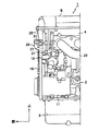
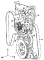
図1は本発明に係るタイミングチェーンカバー構造を備えた車両用エンジン前部の左側面図、図2は同車両用エンジンのタイミングチェーンカバーと補機駆動系の構成を示す正面図、図3は同斜視図、図4はタイミングチェーンカバーの外面図、図5は同タイミングカバーの左側面図、図6は同タイミングチェーンカバーの内面図である。 FIG. 1 is a left side view of a front portion of a vehicle engine provided with a timing chain cover structure according to the present invention, FIG. 2 is a front view showing the configuration of the timing chain cover and auxiliary drive system of the vehicle engine, and FIG. FIG. 4 is an external view of the timing chain cover, FIG. 5 is a left side view of the timing cover, and FIG. 6 is an internal view of the timing chain cover.
図1に示す車両用エンジン1は、4サイクルのDOHC多気筒エンジンであって、不図示の車両前部に縦置き状態で搭載されている。この車両用エンジン1のシリンダブロック2の下部にはオイルパン3が取り付けられ、同シリンダブロック2の上部にはシリンダヘッド4が被着され、該シリンダヘッド4の上部にはヘッドカバー5が被着されている。
A
上記シリンダブロック2には、図2に示すように、クランク軸6が車両前後方向(図2の紙面垂直方向)に配されており、その前端にはクランクプーリ7が結着されている。
As shown in FIG. 2, the
そして、図2に示すように、シリンダブロック2やシリンダヘッド4で構成されるエンジン本体の前部の幅方向両側部には、前記クランク軸6で駆動される補機としてパワーステアリング用ポンプ8、オルタネータ9、ウォータポンプ10及びエアコン用コンプレッサ11が配設されている。そして、これらのパワーステアリング用ポンプ8、オルタネータ9、ウォータポンプ10及びエアコン用コンプレッサ11の各補機プーリ12,13,14,15と前記クランクプーリ7との間には無端状の補機駆動用ベルト16が巻き掛けられている。尚、図2において、17,18はアイドラプーリ、19はオートテンショナプーリであり、これらにも前記補機駆動用ベルト16が巻き掛けられている。
As shown in FIG. 2, a power steering pump 8 as an auxiliary machine driven by the
ところで、前記シリンダヘッド4に各気筒毎に設けられた不図示の吸・排気バルブは、動弁機構によって適当なタイミングで開閉され、これによって各気筒のシリンダ内で所要のガス交換がなされるが、動弁機構は、クランク軸6に取り付けられた不図示のクランクスプロケットと図2に示す吸気カム軸20と排気カム軸21にそれぞれ取り付けられたカムスプロケット22,23間にタイミングチェーン24を巻き掛けて構成されている。この動弁機構においては、クランク軸6の回転がクランクスプロケットとタイミングチェーン24及びカムスプロケット22,23を経て吸気カム軸20と排気カム軸21にそれぞれ伝達され、これらの吸気カム軸20と排気カム軸21が回転駆動されることによって吸・排気バルブがそれぞれ適当なタイミングで開閉される。尚、図示しないが、本実施の形態に係る動弁機構には、吸気バルブの開閉タイミングを可変とする可変バルブタイミング機構が設けられている。
By the way, an intake / exhaust valve (not shown) provided for each cylinder in the
而して、前記タイミングチェーン24はタイミングチェーンカバー25によって覆われるが、該タイミングチェーンカバー25は、図1に示すように、前記補機駆動用ベルト16の後方に配され、その周縁部に形成された複数のボルト挿通孔26(図3、図4及び図6参照)に挿通する取付ボルト27(図1参照)によってシリンダブロック2とシリンダヘッド4の各前面に取り付けられている。尚、図1において、28は排気マニホールドである。
Thus, the
ここで、前記タイミングチェーンカバー25の構成の詳細について説明する。
Here, the details of the configuration of the
図2〜図4に示すように、タイミングチェーンカバー25の外面上部にはエンジンマウント取付部29が突設されており、このエンジンマウント取付部29の側部には円筒状のオイルコントロールバルブ取付部30が一体に形成され、このオイルコントロールバルブ取付部30には、前記バルブタイミング可変機構(不図示)に供給される作動油を制御するためのオイルコントロールバルブ31が挿入されて取り付けられている(図2参照)。
As shown in FIGS. 2 to 4, an engine
而して、本実施の形態においては、タイミングチェーンカバー25の外面の前記エンジンマウント取付部29及びオイルコントロールバルブ取付部30よりも下方の前記補機駆動用ベルト16を避けた位置には、補機駆動用ベルト16と幅方向においてオーバーラップする高さを有し且つ当該タイミングチェーンカバー25の周縁部に向かって幅が広がる正面視三角形の3つの外側補強リブ32,33,34が突設されている。又、タイミングチェーンカバー25の外面の外側補強リブ34に隣接する部位にはタイミングマーク35が突設されている。
Thus, in the present embodiment, the
又、タイミングチェーンカバー25においては、これをクランク軸6方向から透視したとき、該タイミングチェーンカバー25の内面のタイミングチェーン24で囲まれる領域には、図6に示すように、前記カムスプロケット22,23(図2参照)の下方から前記クランクスプロケット(不図示)の上方へと延びる弓状に湾曲した縦リブ36が突設されており、この縦リブ36に前記外側補強リブ32〜34が連結されている。
In addition, when the
更に、図6に示すように、タイミングチェーンカバー25の内面には、前記外側補強リブ32〜34と前記縦リブ36の交点で互いに交差するとともに両端部が当該タイミングチェーンカバー25の周縁部に連結された格子状リブ37が突設されている。
Further, as shown in FIG. 6, the inner surface of the
又、図4及び図6に示すように、タイミングチェーンカバー25の右側周縁部の上下には、前記アイドラプーリ17,18(図2参照)を取り付けるためのアイドラプーリ取付ボス38,39が形成されており、該アイドラプーリ取付ボス38,39の周辺に前記外側補強リブ32,34がそれぞれ配設されている。そして、図6に示すように、タイミングチェーンカバー25の内面には、前記アイドラプーリ取付ボス38,39を囲む円弧状リブ40,41がそれぞれ突設されており、該円弧状リブ40,41の中間部が正面視で前記外側補強リブ32,34にそれぞれ重ねられるとともに、各円弧状リブ40,41の両端部がタイミングチェーンカバー25の周縁部に連結されている。
As shown in FIGS. 4 and 6, idler
以上において、本実施の形態によれば、補機駆動用ベルト16と幅方向においてオーバーラップする高さを有する高さの高い外側補強リブ32〜34を補機駆動用ベルト16との干渉を避けて配設するとともに、該外側補強リブ32〜34の幅をタイミングチェーンカバー25の周縁部に向かって広げたため、外側補強リブ32〜34をタイミングチェーンカバー25の周縁部を介してエンジン本体(シリンダブロック2とシリンダヘッド4)に強固に連結することができ、該外側補強リブ32〜34によってタイミングチェーンカバー25の剛性を効率的に高めて騒音と振動を効果的に抑制することができる。
As described above, according to the present embodiment, the high-side outer reinforcing
又、本実施の形態に係るタイミングチェーンカバー25にあっては、その中央部にエンジン本体との締結点が設けられていないため、該タイミングチェーンカバー25の着脱性が害されることがなく、重量増加を招くこともない。
Further, in the
更に、本実施の形態によれば、タイミングチェーンカバー25の外面に突設された外側補強リブ32〜34をタイミングチェーンカバー25の内面に突設された高さの高い縦リブ36に連結するようにしたため、タイミングチェーンカバー25の面剛性が高められ、該タイミングチェーンカバー25から発生する騒音と振動を一層効果的に低く抑えることができる。
Furthermore, according to the present embodiment, the outer reinforcing
そして、本実施の形態では、タイミングチェーンカバー25の内面に、外側補強リブ32〜34と縦リブ36の交点で互いに交差するとともに両端部がタイミングチェーンカバー25の周縁部に連結された格子状リブ37を突設したため、外側補強リブ32〜34と縦リブ36の交点周辺の変形が格子状リブ37によって抑制され、タイミングチェーンカバー25から発生する騒音と振動を効果的に低減させることができる。
In the present embodiment, lattice ribs are formed on the inner surface of the
又、本実施の形態においては、タイミングチェーンカバー25の周縁部に形成されたアイドラプーリ取付ボス38,39の周辺に外側補強リブ32,34を配設したため、補機駆動用ベルト16との干渉を避けつつ外側補強リブ32,34のリブ幅を容易に拡大することができ、タイミングチェーンカバー25から発生する騒音と振動を効果的に低減させることができる。
In the present embodiment, since the outer reinforcing
更に、本実施の形態では、タイミングチェーンカバー25の内面に、アイドラプーリ取付ボス38,39を囲む円弧状リブ40,41を突設し、該円弧状リブ40,41の中間部を正面視で外側補強リブ32,34に重ねるとともに両端部をタイミングチェーンカバー25の周縁部に連結したため、円弧状リブ40,41を介してアイドラプーリ17,18の周辺に配設された外側補強リブ32,34をタイミングチェーンカバー25の周縁部に強固に連結することができ、タイミングチェーンカバー25から発生する騒音と振動を効果的に低減させることができる。
Further, in the present embodiment, arc-shaped
1 車両用エンジン
2 シリンダブロック
3 オイルパン
4 シリンダヘッド
5 ヘッドカバー
6 クランク軸
7 クランクプーリ
8 パワーステアリング用ポンプ(補機)
9 オルタネータ(補機)
10 ウォータポンプ(補機)
11 エアコン用コンプレッサ(補機)
12〜15 補機プーリ
16 補機駆動用ベルト
17,18 アイドラプーリ
19 オートテンショナプーリ
20 吸気カム軸
21 排気カム軸
22,23 カムスプロケット
24 タイミングチェーン
25 タイミングチェーンカバー
26 ボルト挿通孔
27 取付ボルト
28 排気マニホールド
29 エンジンマウント用取付部
30 オイルコントロールバルブ取付部
31 オイルコントロールバルブ
32〜34 外側補強リブ
35 タイミングマーク
36 縦リブ
37 格子状リブ
38,39 アイドラプーリ取付ボス
40,41 円弧状リブ
DESCRIPTION OF
9 Alternator (auxiliary machine)
10 Water pump (auxiliary machine)
11 Air conditioner compressor (auxiliary)
12-15
Claims (5)
前記タイミングチェーンカバー外面の前記補機駆動用ベルトを避けた位置に、前記補機駆動用ベルトと幅方向においてオーバーラップする高さを有し且つ当該タイミングチェーンカバーの周縁部に向かって幅が広がる外側補強リブを突設したことを特徴とするエンジンのタイミングチェーンカバー構造。 Auxiliary machinery driven by the crankshaft is arranged on both sides in the width direction of the engine body, and an auxiliary machinery driving belt is wound between the crank pulley attached to the crankshaft and the auxiliary pulley attached to each auxiliary machinery. A timing chain cover covering a timing chain wound between a crank sprocket attached to the crankshaft and a cam sprocket attached to the camshaft is disposed behind the auxiliary machine driving belt, and the timing chain cover is In the engine timing chain cover structure, which is fastened to the engine body by a plurality of cover mounting bolts inserted through the peripheral edge portion thereof,
The timing chain cover has a height that overlaps the accessory driving belt in the width direction at a position avoiding the accessory driving belt on the outer surface of the timing chain cover, and the width increases toward the peripheral edge of the timing chain cover. An engine timing chain cover structure characterized by protruding outer reinforcing ribs.
An arc-shaped rib is formed on the inner surface of the timing chain cover so as to surround the idler pulley mounting boss, and an intermediate portion of the arc-shaped rib is overlapped with the outer reinforcing rib in a front view, and both ends are peripheral edges of the timing chain cover. The engine timing chain cover structure according to claim 4, wherein the engine timing chain cover structure is connected to a portion.
Priority Applications (1)
| Application Number | Priority Date | Filing Date | Title |
|---|---|---|---|
| JP2008022365A JP2009180363A (en) | 2008-02-01 | 2008-02-01 | Timing chain cover structure for engine |
Applications Claiming Priority (1)
| Application Number | Priority Date | Filing Date | Title |
|---|---|---|---|
| JP2008022365A JP2009180363A (en) | 2008-02-01 | 2008-02-01 | Timing chain cover structure for engine |
Publications (1)
| Publication Number | Publication Date |
|---|---|
| JP2009180363A true JP2009180363A (en) | 2009-08-13 |
Family
ID=41034495
Family Applications (1)
| Application Number | Title | Priority Date | Filing Date |
|---|---|---|---|
| JP2008022365A Pending JP2009180363A (en) | 2008-02-01 | 2008-02-01 | Timing chain cover structure for engine |
Country Status (1)
| Country | Link |
|---|---|
| JP (1) | JP2009180363A (en) |
Cited By (4)
| Publication number | Priority date | Publication date | Assignee | Title |
|---|---|---|---|---|
| CN102588098A (en) * | 2012-02-28 | 2012-07-18 | 长城汽车股份有限公司 | Automobile engine accessory gear train layout |
| CN102588142A (en) * | 2012-03-14 | 2012-07-18 | 重庆长安汽车股份有限公司 | Engine front shield and method for adjusting timing system of engine with front shield |
| JP2015227635A (en) * | 2014-05-30 | 2015-12-17 | 本田技研工業株式会社 | Internal combustion engine cover structure |
| CN113557153A (en) * | 2019-03-14 | 2021-10-26 | 日产自动车株式会社 | Internal combustion engine |
-
2008
- 2008-02-01 JP JP2008022365A patent/JP2009180363A/en active Pending
Cited By (5)
| Publication number | Priority date | Publication date | Assignee | Title |
|---|---|---|---|---|
| CN102588098A (en) * | 2012-02-28 | 2012-07-18 | 长城汽车股份有限公司 | Automobile engine accessory gear train layout |
| CN102588142A (en) * | 2012-03-14 | 2012-07-18 | 重庆长安汽车股份有限公司 | Engine front shield and method for adjusting timing system of engine with front shield |
| JP2015227635A (en) * | 2014-05-30 | 2015-12-17 | 本田技研工業株式会社 | Internal combustion engine cover structure |
| CN113557153A (en) * | 2019-03-14 | 2021-10-26 | 日产自动车株式会社 | Internal combustion engine |
| CN113557153B (en) * | 2019-03-14 | 2024-05-31 | 日产自动车株式会社 | Internal combustion engine |
Similar Documents
| Publication | Publication Date | Title |
|---|---|---|
| JP4895021B2 (en) | Engine mount structure with variable valve timing mechanism | |
| JP2008215323A (en) | Engine with variable valve timing mechanism | |
| JP5354462B2 (en) | Engine chain case structure | |
| JP2009180363A (en) | Timing chain cover structure for engine | |
| JP5574270B2 (en) | Engine chain case structure | |
| JP5045887B2 (en) | Engine chain case structure | |
| JP5180951B2 (en) | Internal combustion engine timing train cover | |
| JP6615254B2 (en) | Internal combustion engine | |
| JP4321517B2 (en) | Oil control valve mounting structure | |
| JP4900586B2 (en) | Engine with variable valve timing mechanism | |
| JP2007198160A (en) | Accessary mounting structure for engine | |
| JP5220167B2 (en) | Internal combustion engine | |
| JP4310595B2 (en) | Engine accessory mounting structure | |
| JP7347106B2 (en) | Engine chain cover structure | |
| JP4858562B2 (en) | Oil control valve mounting structure | |
| US6179582B1 (en) | Oil pump attachment structure for engine | |
| JP2007016715A (en) | Engine fuel pump mounting structure | |
| JP2021063494A (en) | Auxiliary machine mounting structure for engine | |
| JP4085910B2 (en) | Engine power transmission mechanism cover member | |
| JP7383974B2 (en) | Engine chain cover structure | |
| JPH06108919A (en) | Oil pan structure of engine | |
| JP2001199248A (en) | Mount installing structure for engine | |
| JP2008184924A (en) | Engine | |
| JP7395945B2 (en) | Engine cover structure | |
| JP2009243403A (en) | Oil pan |