JP2009166318A - Instrument for inspecting vulcanized tire and method thereof - Google Patents
Instrument for inspecting vulcanized tire and method thereof Download PDFInfo
- Publication number
- JP2009166318A JP2009166318A JP2008005755A JP2008005755A JP2009166318A JP 2009166318 A JP2009166318 A JP 2009166318A JP 2008005755 A JP2008005755 A JP 2008005755A JP 2008005755 A JP2008005755 A JP 2008005755A JP 2009166318 A JP2009166318 A JP 2009166318A
- Authority
- JP
- Japan
- Prior art keywords
- tire
- vulcanized tire
- vulcanized
- type display
- reading
- Prior art date
- Legal status (The legal status is an assumption and is not a legal conclusion. Google has not performed a legal analysis and makes no representation as to the accuracy of the status listed.)
- Granted
Links
- 238000000034 method Methods 0.000 title claims abstract description 9
- 238000004073 vulcanization Methods 0.000 claims abstract description 27
- 238000001514 detection method Methods 0.000 claims abstract description 14
- 238000007689 inspection Methods 0.000 claims description 22
- 238000005259 measurement Methods 0.000 claims description 21
- 239000000470 constituent Substances 0.000 claims description 4
- NINIDFKCEFEMDL-UHFFFAOYSA-N Sulfur Chemical compound [S] NINIDFKCEFEMDL-UHFFFAOYSA-N 0.000 claims 1
- 229910052717 sulfur Inorganic materials 0.000 claims 1
- 239000011593 sulfur Substances 0.000 claims 1
- 230000002093 peripheral effect Effects 0.000 description 9
- 239000011324 bead Substances 0.000 description 7
- 238000004519 manufacturing process Methods 0.000 description 5
- 238000010586 diagram Methods 0.000 description 2
- 230000000694 effects Effects 0.000 description 2
- 230000003247 decreasing effect Effects 0.000 description 1
- 238000006073 displacement reaction Methods 0.000 description 1
- 239000002184 metal Substances 0.000 description 1
Images


Landscapes
- Tyre Moulding (AREA)
- Chemical & Material Sciences (AREA)
- Health & Medical Sciences (AREA)
- Chemical Kinetics & Catalysis (AREA)
- Medicinal Chemistry (AREA)
- Polymers & Plastics (AREA)
- Organic Chemistry (AREA)
Abstract
Description
本発明は、例えば自動車用空気入りタイヤの製造工程において、加硫成形後のタイヤを検査する加硫タイヤの検査装置及びその方法に関するものである。 The present invention relates to a vulcanized tire inspection apparatus and method for inspecting a vulcanized tire in, for example, an automobile pneumatic tire manufacturing process.
一般に、この種の加硫タイヤの検査装置としては、加硫用金型によって幅方向一方の側面に凹凸状のバーコード表示部が形成された加硫タイヤを横置き状態で所定方向に搬送可能なコンベアと、コンベアの途中に設けられ、コンベアによって搬送されている加硫タイヤを横置き状態で回転自在に支持する支持装置と、支持装置によって回転支持されている加硫タイヤのバーコード表示部の表示情報を読取るバーコードリーダとを備えたものが知られている(例えば、特許文献1参照。)。
ところで、前記検査装置では、加硫タイヤのバーコード表示部がその加硫タイヤの製品コード等の情報を有しており、読取った情報からその加硫タイヤの製品コードを判定することができるので、例えば搬送コンベアの前記検査装置よりも下流側において、加硫タイヤを製品コードごとに異なる搬送経路に自動的に振り分けることが可能である。 By the way, in the inspection device, the bar code display part of the vulcanized tire has information such as the product code of the vulcanized tire, and the product code of the vulcanized tire can be determined from the read information. For example, it is possible to automatically distribute the vulcanized tires to different conveyance paths for each product code on the downstream side of the inspection device of the conveyance conveyor.
しかしながら、前記加硫タイヤのバーコード表示部は加硫用金型によって形成されるので、未加硫タイヤを間違った加硫用金型で加硫した場合でも、その加硫タイヤは前記検査装置によってバーコード表示部に表示された製品コードの加硫タイヤとして判定される。即ち、前記検査装置によって加硫タイヤが検査された後に、その加硫タイヤの加硫に正しい加硫用金型が用いられたか否かを例えば目視によって検査する必要があり、目視検査を行う分だけ生産効率が低下するという問題点があった。 However, since the bar code display part of the vulcanized tire is formed by a vulcanizing mold, even when an unvulcanized tire is vulcanized by an incorrect vulcanizing mold, the vulcanized tire is Is determined as a vulcanized tire of the product code displayed on the bar code display. That is, after the vulcanized tire is inspected by the inspection device, it is necessary to inspect for example whether the correct vulcanizing mold is used for vulcanizing the vulcanized tire. There was a problem that the production efficiency only decreased.
一方、未加硫タイヤはカーカス部材やサイド部材の周方向の端部が重ね合わせられたスプライス部を有しており、加硫タイヤにおいて前記スプライス部があった位置の特性と他の位置の特性との差を小さくすることができれば、加硫タイヤの周方向の均一性を向上することができる。また、加硫用金型は一般に高い寸法精度で形成されているが、わずかな寸法誤差の発生を完全に防止することは難しく、キャビティを全周に亘って均一に形成することが難しい。さらに、同一製品コード用の加硫用金型が複数ある場合、各加硫用金型は前記寸法誤差によってそれぞれ異なる特性を有している。このため、未加硫タイヤを加硫用金型内に配置する際に、スプライス部をその加硫用金型の特性に応じた位置に配置することにより、加硫タイヤの周方向の均一性を向上することができる。しかしながら、スプライス部を配置する位置は加硫用金型ごとに異なるので、加硫タイヤの周方向の均一性を向上可能な加硫用金型内におけるスプライス部の配置を容易に特定することができないという問題点があった。 On the other hand, the unvulcanized tire has a splice portion in which the end portions in the circumferential direction of the carcass member and the side member are overlapped, and the characteristics of the position where the splice portion was present in the vulcanized tire and the characteristics of other positions Can be reduced, the uniformity in the circumferential direction of the vulcanized tire can be improved. Further, although the vulcanization mold is generally formed with high dimensional accuracy, it is difficult to completely prevent a slight dimensional error, and it is difficult to form the cavity uniformly over the entire circumference. Further, when there are a plurality of vulcanization molds for the same product code, each vulcanization mold has different characteristics depending on the dimensional error. For this reason, when placing an unvulcanized tire in a vulcanizing mold, the spliced portion is arranged at a position corresponding to the characteristics of the vulcanizing mold, thereby making it possible to achieve uniformity in the circumferential direction of the vulcanized tire. Can be improved. However, since the position where the splice part is arranged differs for each vulcanization mold, it is possible to easily specify the arrangement of the splice part in the vulcanization mold that can improve the uniformity in the circumferential direction of the vulcanized tire. There was a problem that it was not possible.
本発明は前記問題点に鑑みてなされたものであり、その目的とするところは、加硫タイヤが正しい加硫用金型によって加硫されたか否かを容易且つ確実に検査することが可能であり、また、加硫タイヤの周方向の均一性を向上可能な加硫用金型内におけるスプライス部の配置を容易に特定可能な加硫タイヤの検査装置及びその方法を提供することにある。 The present invention has been made in view of the above problems, and the object of the present invention is to easily and reliably inspect whether or not the vulcanized tire has been vulcanized by a correct vulcanization mold. Another object of the present invention is to provide a vulcanized tire inspection apparatus and method capable of easily specifying the arrangement of splice parts in a vulcanization mold that can improve the uniformity in the circumferential direction of the vulcanized tire.
本発明は前記目的を達成するために、タイヤ幅方向の何れか一方の側面に貼付型表示部材が貼付された未加硫タイヤを加硫用金型で加硫して成る加硫タイヤを検査する加硫タイヤの検査装置において、前記加硫用金型によって加硫タイヤにおける幅方向一方の側面に形成された凹凸状表示部の表示情報を読取る第1読取装置と、加硫タイヤに貼付されている貼付型表示部材の表示情報を読取る第2読取装置とを備えている。 In order to achieve the above-mentioned object, the present invention inspects a vulcanized tire obtained by vulcanizing an unvulcanized tire having a pasting type display member affixed on one side surface in the tire width direction with a vulcanizing mold. In the inspection apparatus for a vulcanized tire, a first reading device that reads display information of a concavo-convex display portion formed on one side surface in the width direction of the vulcanized tire by the vulcanizing mold, and affixed to the vulcanized tire And a second reading device for reading display information of the pasting type display member.
これにより、タイヤ幅方向の何れか一方の側面に貼付型表示部材が貼付された未加硫タイヤが加硫用金型によって加硫されるとともに、加硫用金型によってタイヤ幅方向一方の側面に凹凸状表示部が形成され、第1読取装置によって凹凸状表示部の表示情報が読取られ、第2読取装置によって貼付型表示部材の表示情報が読取られることから、凹凸状表示部材から読取られる情報と貼付型表示部材から読取られる情報を比較することにより、加硫タイヤが正しい加硫用金型によって加硫されたか否かを容易且つ確実に検査することが可能である。 As a result, the unvulcanized tire having the sticking type display member pasted on any one side surface in the tire width direction is vulcanized by the vulcanizing mold, and one side surface in the tire width direction by the vulcanizing mold. An uneven display portion is formed on the surface, the display information of the uneven display portion is read by the first reading device, and the display information of the pasting type display member is read by the second reading device, so that it is read from the uneven display member. By comparing the information and the information read from the sticking type display member, it is possible to easily and reliably inspect whether or not the vulcanized tire has been vulcanized by a correct vulcanization mold.
また、本発明は、タイヤ幅方向の何れか一方の側面におけるタイヤ構成部材のスプライス部に貼付型表示部材が貼付された未加硫タイヤを加硫用金型で加硫して成る加硫タイヤを検査する加硫タイヤの検査方法において、前記加硫用金型によって加硫タイヤにおける幅方向一方の側面に形成された凹凸状表示部の表示情報を第1読取手段によって読取るとともに、加硫タイヤに貼付されている貼付型表示部材の表示情報を第2読取手段によって読取る読取工程と、凹凸状表示部のタイヤ周方向の位置と貼付型表示部材のタイヤ周方向の位置との角度差を検出する角度差検出工程と、角度差検出工程の検出結果を貼付型表示部材の表示情報と対応するように保存する第1保存工程と、加硫タイヤの周方向の均一性を測定する均一性測定工程と、均一性測定工程の測定結果を貼付型表示部材の表示情報と対応するように保存する第2保存工程と、第1保存工程によって保存した角度差の検出結果と第2保存工程によって保存した均一性の測定結果とを貼付型表示部材の表示情報を介して対応させる対応工程とを含むようにしている。 Further, the present invention relates to a vulcanized tire obtained by vulcanizing an unvulcanized tire in which a pasting type display member is pasted on a splice portion of a tire constituent member on any one side surface in the tire width direction with a vulcanizing mold. In the method for inspecting a vulcanized tire, the display information of the concavo-convex display portion formed on one side surface in the width direction of the vulcanized tire by the vulcanizing mold is read by the first reading means, and the vulcanized tire A display step of reading the display information of the sticking type display member affixed to the sheet by the second reading means, and detecting an angular difference between the position of the uneven display portion in the tire circumferential direction and the position of the sticking type display member in the tire circumferential direction Angle difference detecting step, a first storing step for storing the detection result of the angle difference detecting step so as to correspond to the display information of the pasting type display member, and uniformity measurement for measuring the circumferential uniformity of the vulcanized tire Process, A second storage step for storing the measurement result of the uniformity measurement step so as to correspond to the display information of the pasting type display member, an angle difference detection result stored by the first storage step, and a uniformity stored by the second storage step And a corresponding process for making the measurement result correspond to each other via the display information of the pasting type display member.
これにより、タイヤ幅方向の何れか一方の側面に貼付型表示部材が貼付された未加硫タイヤが加硫用金型によって加硫されるとともに、加硫用金型によってタイヤ幅方向一方の側面に凹凸状表示部が形成され、凹凸状表示部の表示情報を読取るとともに、貼付型表示部材の表示情報を読取ることから、凹凸状表示部材から読取られる情報と貼付型表示部材から読取られる情報を比較することにより、加硫タイヤが正しい加硫用金型によって加硫されたことを容易且つ確実に検査することが可能である。また、貼付型表示部材は未加硫タイヤにおけるタイヤ構成部材のスプライス部に貼付されているので、凹凸状表示部のタイヤ周方向の位置と貼付型表示部材のタイヤ周方向の位置との角度差を検出することにより、加硫用金型内におけるスプライス部の位置を判定することが可能となる。さらに、角度差の検出結果と加硫タイヤにおける周方向の均一性の測定結果とを貼付型表示部材の表示情報を介して対応させていることから、貼付型表示部材がシリアル番号等の加硫タイヤごとに異なる情報を有している場合には、加硫用金型内におけるスプライス部の位置と加硫タイヤの周方向の均一性との関係を容易に得ることができる。 As a result, the unvulcanized tire having the sticking type display member pasted on any one side surface in the tire width direction is vulcanized by the vulcanizing mold, and one side surface in the tire width direction by the vulcanizing mold. In addition to reading the display information of the uneven display portion and reading the display information of the sticking type display member, the information read from the uneven display member and the information read from the sticking type display member are read. By comparing, it is possible to easily and reliably inspect that the vulcanized tire has been vulcanized by the correct vulcanization mold. Further, since the sticking type display member is stuck to the splice portion of the tire component member in the unvulcanized tire, the angular difference between the position in the tire circumferential direction of the uneven display portion and the position in the tire circumferential direction of the sticking type display member By detecting this, it is possible to determine the position of the splice part in the vulcanization mold. Further, since the detection result of the angle difference and the measurement result of the uniformity in the circumferential direction of the vulcanized tire are associated with each other via the display information of the sticking type display member, the sticking type display member is vulcanized such as a serial number. When there is different information for each tire, the relationship between the position of the splice part in the vulcanizing mold and the uniformity in the circumferential direction of the vulcanized tire can be easily obtained.
本発明によれば、加硫タイヤが正しい加硫用金型によって加硫されたか否かを容易且つ確実に検査することができるので、タイヤの生産効率を向上する上で極めて有利である。また、加硫用金型内におけるスプライス部の位置と加硫タイヤの周方向の均一性との関係を容易に得ることができるので、加硫タイヤの周方向の均一性を向上可能な加硫用金型内におけるスプライス部の配置を容易に特定することができ、タイヤ品質の向上を図る上で極めて有利である。 According to the present invention, whether or not a vulcanized tire has been vulcanized by a correct vulcanization mold can be easily and reliably inspected, which is extremely advantageous in improving tire production efficiency. In addition, since the relationship between the position of the splice portion in the vulcanizing mold and the circumferential uniformity of the vulcanized tire can be easily obtained, the vulcanization capable of improving the circumferential uniformity of the vulcanized tire. The arrangement of the splice part in the metal mold can be easily specified, which is extremely advantageous for improving the tire quality.
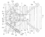
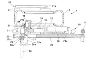
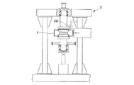
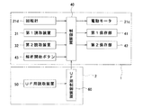
図1乃至図10は本発明の一実施形態を示すもので、図1は加硫タイヤ検査装置の平面図、図2及び図3は図1におけるA−A線断面図、図4はユニフォーミティ測定装置の一部断面正面図、図5は加硫タイヤ検査装置及びユニフォーミティ測定装置のブロック図、図6は制御装置の動作を示すフローチャート、図7は加硫タイヤの断面図、図8は制御装置の動作を示すフローチャート、図9は解析結果の一例を示す表、図10は解析結果の一例を示すグラフである。 1 to 10 show an embodiment of the present invention. FIG. 1 is a plan view of a vulcanized tire inspection apparatus, FIGS. 2 and 3 are cross-sectional views taken along line AA in FIG. 1, and FIG. FIG. 5 is a block diagram of a vulcanized tire inspection device and a uniformity measuring device, FIG. 6 is a flowchart showing the operation of the control device, FIG. 7 is a sectional view of the vulcanized tire, and FIG. FIG. 9 is a flowchart showing an example of the analysis result, and FIG. 10 is a graph showing an example of the analysis result.
この加硫タイヤ検査装置1は、加硫タイヤTを横置き状態で所定の搬送方向に搬送可能な搬送コンベア10と、搬送コンベア10によって搬送されている加硫タイヤTを搬送方向所定位置において横置き状態で回転自在に支持する支持装置20とを備えている。加硫タイヤTは、未加硫タイヤの状態においてタイヤ幅方向の一方におけるサイド部材のスプライス部に周知のQRコード等が印刷された貼付型表示部材QRが貼付されたものであり、加硫用金型によってタイヤ幅方向の一方に周知のバーコード表示から成る凹凸状表示部BAが設けられたものである。凹凸状表示部BAは少なくともそのタイヤの製品コードの情報を有しており、貼付型表示部材QRは少なくともそのタイヤの製品コード及びシリアル番号の情報を有している。
The vulcanized
搬送コンベア10は前記搬送方向に並設けられた複数の搬送ローラ11を有し、各搬送ローラ11のうち一部の搬送ローラ11が回転駆動されることにより、加硫タイヤTを所定方向に搬送するようになっている。また、凹凸状表示部BAが設けられた側が下側に配置されるように加硫タイヤTが搬送される(図2及び図3参照)。搬送コンベア10は一対のアーム12aから成るタイヤ送りゲート12を有し、タイヤ送りゲート12は前記搬送方向所定位置側に加硫タイヤTを1つずつ送り出すようになっている。
The
支持装置20は、搬送コンベア10上の加硫タイヤTに搬送方向下流側から当接可能な一対の外周側ローラ21と、上下方向に回動自在に設けられた回動フレイム22と、回動フレイム22の上面に設けられた第1支持ローラ23と、回動フレイム22に固定された複数の第2支持ローラ24と、回動フレイム22に前記搬送方向に移動自在に取付けられた可動フレイム25と、可動フレイム25の先端に設けられた一対の内周側ローラ26とを有する。
The
各外周側ローラ21は上下方向に延びる円筒状に形成され、それぞれアーム21aの一端に回転可能に支持されている。各アーム21aは搬送コンベア10の幅方向に回動可能となるように他端を支持されている。このため、各アーム21aが搬送コンベア10の幅方向内側に回動し、各アーム21aが図1における実線の位置に配置されると、各外周側ローラ21が加硫タイヤTの外周面に搬送方向下流側から当接し、タイヤ送りゲート12から送り出された加硫タイヤTを搬送コンベア10上で停止させることができる。この加硫タイヤTが停止する位置が前記搬送方向所定位置である。また、各アーム21aが搬送コンベア10の幅方向外側に回動し、各アーム21aが図1における二点鎖線の位置に配置されると、搬送方向所定位置に保持されていた加硫タイヤTが搬送コンベア10上を搬送方向下流側に移動する。各外周側ローラ21のうち一方の外周側ローラ21にベルト21bを介して駆動力を加える電動モータ21cが設けられ、電動モータ21cの回転量を検出する回転計21dも設けられている。
Each
回動フレイム22は矩形板状に形成されるとともに、上下方向に回動可能となるように一端を支持され、図示しないエアシリンダによって上下方向に回動するようになっている。各外周側ローラ21によって加硫タイヤTが搬送方向所定位置に配置されている状態で、回動フレイム22が上側に回動し、回動フレイム22が図2に示す位置に配置されると、回動フレイム22に設けられた各支持ローラ23,24が搬送コンベア10の各搬送ローラ11よりも上方に突出し、加硫タイヤTが各支持ローラ23,24によって支持される。ここで、各支持ローラ23,24は加硫タイヤTを回転可能に支持するように形成されている。一方、回動フレイム22が下側に回動し、回動フレイム22が図3に示す位置に配置されると、回動フレイム22に設けられた各支持ローラ23,24が搬送コンベア10の各搬送ローラ11の下方に配置され、各支持ローラ23,24によって支持されていた加硫タイヤTが各搬送ローラ11上に載置される。回動フレイム22の上面には一対のレール22aが設けられ、各レール22aは前記搬送方向に延びるように形成されている。
The
可動フレイム25は各レール22aに移動可能に係合し、図示しないエアシリンダの駆動力によって各レール22a上を移動するようになっている。即ち、可動フレイム25は前記搬送方向に移動自在である。各内周側ローラ26は上下方向に延びる円筒状に形成され、互いに搬送ローラ10の幅方向に並ぶように配置されている。各外周側ローラ21によって加硫タイヤTが搬送方向所定位置に配置されるとともに、各支持ローラ23,24によって加硫タイヤTが支持されている状態で、可動フレイム25が搬送方向下流側に移動すると、各内周側ローラ26が加硫タイヤTのビード部にタイヤ径方向の内側から当接する。これにより、加硫タイヤTが搬送方向所定位置において径方向に位置決めされる。可動フレイム25の先端側には上下方向に延びるレール25aが固定されている。
The
可動フレイム25の先端側には可動部材27が設けられ、可動部材27は可動フレイム25のレール25aに上下方向に移動可能に係合している。また、可動部材27の下方には上下方向に移動自在なロッド28aを有するエアシリンダ28が設けられ、エアシリンダ28は可動フレイム25のレール25aの下端に固定されている。エアシリンダ28のロッド28aの長さ方向の中間部分には板状部材28bが固定されるとともに、可動部材27の下端にも板状部材27aが設けられ、各板状部材27a,28bは互いに対向するように配置されている。また、エアシリンダ28のロッド28aの上端は板状部材27aを上下方向に挿通している。さらに、板状部材28bと板状部材27aとの間にはコイルスプリング29が設けられ、エアシリンダ28のロッド28aはコイルスプリング29を上下方向に挿通している。可動部材27の上端には回転可能な当接ローラ27bが設けられている。さらに、可動部材27には周知のレーザー変位計から成るとともに凹凸状表示部BAをバーコードとして読取可能な第1読取装置31が取付けられ、また、可動部材27には周知のCCDカメラから成るとともにQRコードを読取可能な第2読取装置32も取付けられている。各外周側ローラ21によって加硫タイヤTが搬送方向所定位置に配置されるとともに、各支持ローラ23,24によって加硫タイヤTが支持されている状態で、エアシリンダ28によって可動部材27を上方に移動させると、当接ローラ27bが加硫タイヤTのタイヤ幅方向一方のビード部に下方から当接し、当接ローラ27bが当接した後の可動部材27の上方への移動がスプリング29によって吸収される(図2参照)。即ち、エアシリンダ28及びスプリング29は、当接ローラ27bが加硫タイヤTの側面のビード部に当接するように、可動部材を加硫タイヤT側に向かって付勢するようになっている。これにより、当接ローラ27bを加硫タイヤTのビード部に確実に当接させることができ、可動部材27に取付けられた各読取装置31,32と加硫タイヤTとの距離を常に一定に保つことができる。ここで、当接ローラ27bは加硫タイヤTの回転を許容するように形成されている。
A
回転計21d、第1読取装置31及び第2読取装置32は例えば周知のマイクロコンピュータから成る制御装置40に接続されている。また、制御装置40には例えば周知のハードディスクから成る第1保存部41及び第2保存部42が接続されている。
The
以上のように構成された加硫タイヤ検査装置において、加硫タイヤTを検査する場合は、先ず、タイヤ送りゲート12によって搬送コンベア10上の加硫タイヤTが1つだけ送り出され、その加硫タイヤTが各外周側ローラ21によって搬送方向所定位置に配置される。この時、回動フレイム22は下側に回動した状態になっている。続いて、回動フレイム22が上側に回動し、各支持ローラ23,24によって加硫タイヤTが支持される。続いて、可動フレイム25が搬送方向下流側に移動し、各内側ローラ26が加硫タイヤTのビード部に径方向内側から当接する。これにより、加硫タイヤTが搬送方向所定位置において横置き状態で支持される。また、可動部材27が上方に移動し、可動部材27の当接ローラ27bが加硫タイヤTのビード部に当接する。
In the vulcanized tire inspection apparatus configured as described above, when inspecting the vulcanized tire T, first, only one vulcanized tire T on the
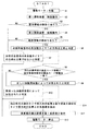
次に、加硫タイヤTを回転させながら、加硫タイヤTの凹凸状表示部BA及び貼付型表示部材QRの表示情報を第1読取装置31及び第2読取装置32によってそれぞれ読取る。この時の制御装置40の動作について図6に示すフローチャートを参照しながら説明する。
Next, while the vulcanized tire T is rotated, the display information on the concavo-convex display portion BA and the sticking display member QR of the vulcanized tire T is read by the
先ず、電動モータ21cを作動させる(S1)。これにより、加硫タイヤTが搬送方向所定位置で回転する。続いて、第1読取装置31に凹凸状表示部BAの表示情報を読取るための読取動作を行わせる(S2)。ステップS2によって凹凸状表示部BAの表示情報が読取られると(S3)、第2読取装置32に貼付型表示部材QRの表示情報を読取るための読取動作を行わせる(S4)。続いて、ステップS4によって貼付型表示部材QRの表示情報が読取られると(S5)、加硫用金型内における未加硫タイヤTの方向は正常であったと判定する(S6)。一方、ステップS2またはステップS4によって表示情報が読取られない場合は(S2,S4)、加硫用金型内における未加硫タイヤTの方向が正常ではなかったと判定する(S7)。本実施形態では、未加硫タイヤの状態においてタイヤ幅方向の一方に貼付型表示部材QRが貼付され、加硫用金型によってタイヤ幅方向の一方に凹凸状表示部BAが設けられるようになっており、さらに、搬送コンベア10上で凹凸状表示部BAが設けられた側が下側に配置されることから、図7(a)に示すように加硫タイヤTが成形されている場合は、加硫用金型内における未加硫タイヤTの方向は正常であったと判定され、例えば図7(b)に示すように加硫タイヤTが成形されている場合は、加硫用金型内における未加硫タイヤTの方向が正常ではなかったと判定される。
First, the
続いて、ステップS6を行った後に、第1読取装置31によって読取られた製品コード情報と第2読取装置32によって読取られた製品コード情報とが一致している場合は(S8)、正しい加硫用金型によって加硫されたと判定し(S9)、一致していない場合は(S8)、間違った加硫用金型によって加硫されたと判定する(S10)。
Subsequently, after performing step S6, if the product code information read by the
続いて、凹凸状表示部BAのタイヤ周方向の位置と貼付型表示部材QRのタイヤ周方向の位置との角度差を検出する(S11)。例えば、第1読取装置31によって凹凸状表示部BAが読取られた際のタイヤの回転位置を0°とみなし、第2読取装置32によって貼付型表示部材QRが読取られた際のタイヤの回転位置を回転計21dに基づいて検出し、貼付型表示部材QRが検出された際のタイヤの回転位置を前記角度差とすることができる。尚、加硫タイヤTの回転位置を直接回転計等によって検出することも可能である。
Subsequently, an angular difference between the position in the tire circumferential direction of the concavo-convex display portion BA and the position in the tire circumferential direction of the pasting type display member QR is detected (S11). For example, the rotational position of the tire when the uneven display portion BA is read by the
続いて、ステップS11で検出した角度差を貼付型表示部材QRのシリアル番号の情報と対応するように第1保存部41に保存し(S12)、電動モータ21cを停止させる(S13)。
Subsequently, the angle difference detected in step S11 is stored in the
以上のように凹凸状表示部BA及び貼付型表示部材QRの表示情報を読取った後は、可動部材27、可動フレイム25及び回動フレイム22をそれぞれ移動または回動するとともに、各外周側ローラ21を搬送コンベア10の幅方向外側に移動することにより、加硫タイヤTが搬送コンベア10を搬送方向下流側に搬送され、例えば図4に示すような周知のユニフォーミティ測定装置2によって周方向の均一性が測定される。
After reading the display information on the concavo-convex display portion BA and the stick-type display member QR as described above, the
この場合、ユニフォーミティ測定装置2には、加硫タイヤTの貼付型表示部材QRの表示情報を読取可能なUF用読取装置50が設けられ、ユニフォーミティ測定装置2による例えばRFV(タイヤ径方向の荷重変動)の測定結果を貼付型表示部材QRから読取ったシリアル番号の情報と対応するように保存可能なUF用制御装置60が設けられている。尚、RFVは加硫タイヤの周方向の均一性を示す特性の一つであり、RFVの代わりにLFV(タイヤ幅方向の荷重変動)等の加硫タイヤの周方向の均一性を示す他の特性を用いることも可能である。また、UF用制御装置60は制御装置40と接続されており、制御装置40には解析開始ボタン43が設けられている。解析開始ボタン43が操作された際の制御装置40の動作について図8に示すフローチャートを参照しながら説明する。
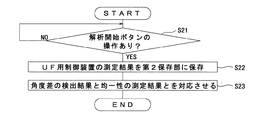
In this case, the
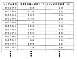
先ず、解析開始ボタン43が操作されると(S21)、シリアル番号の情報と対応するようにUF用制御装置60に保存されているユニフォーミティ測定装置2のRFVの測定結果を第2保存部42に保存する(S22)。続いて、第1保存部31に保存されている角度差の検出結果と第2保存部32に保存されているRFVの測定結果とをシリアル番号の情報を介して対応させる。これにより、例えば図9に示すような表を作成することができるとともに、図10に示すようなグラフを作成することができる。尚、本実施形態ではシリアル番号の情報を介して角度差の検出結果とRFVの測定結果とを対応させるものを示したが、シリアル番号の情報の代わりに加硫タイヤTを一つ一つ判別可能な他の情報を用いることも可能である。
First, when the
このように、本実施形態によれば、タイヤ幅方向の一方の側面に貼付型表示部材QRが貼付された未加硫タイヤが加硫用金型によって加硫されるとともに、加硫用金型によってタイヤ幅方向一方の側面に凹凸状表示部BAが形成され、第1読取装置31によって凹凸状表示部BAの表示情報が読取られ、第2読取手段によって貼付型表示部材QRの表示情報が読取られることから、凹凸状表示部BAから読取られる情報と貼付型表示部材QRから読取られる情報とを比較することにより、その加硫タイヤTが正しい加硫用金型によって加硫されたか否かを容易且つ確実に検査することが可能であり、タイヤの生産効率を向上する上で極めて有利である。
As described above, according to the present embodiment, the unvulcanized tire having the sticking mold display member QR attached to one side surface in the tire width direction is vulcanized by the vulcanizing mold, and the vulcanizing mold is used. Is formed on one side surface in the tire width direction, the display information of the uneven display portion BA is read by the
また、第1読取装置31はタイヤ幅方向一方の側面に設けられた凹凸状表示部BAの表示情報を読取可能であるとともに、第2読取装置32はタイヤ幅方向一方の側面に貼付された貼付型表示部材QRの表示情報を読取可能であり、貼付型表示部材QRは未加硫タイヤにおけるタイヤ幅方向一方の側面に貼付されていることから、加硫用金型内における未加硫タイヤTの方向が正常であったか否かを容易且つ確実に検査することが可能であり、タイヤの生産効率を向上する上で極めて有利である。
Further, the
また、貼付型表示部材QRは未加硫タイヤTにおけるサイド部材のスプライス部に貼付されているので、凹凸状表示部BAのタイヤ周方向の位置と貼付型表示部材QRのタイヤ周方向の位置との角度差を検出することにより、加硫用金型内におけるスプライス部の位置を判定することが可能となる。さらに、角度差の検出結果と加硫タイヤTのRFVの測定結果とを貼付型表示部材QRの表示情報におけるシリアル番号を介して対応させていることから、加硫用金型内におけるスプライス部の位置と加硫タイヤTのRFVの測定結果との関係を容易に得ることができる。即ち、加硫タイヤTの周方向の均一性を向上可能な加硫用金型内におけるスプライス部の配置を容易に特定することができ、タイヤ品質の向上を図る上で極めて有利である。 Further, since the sticking type display member QR is stuck to the splice part of the side member in the unvulcanized tire T, the position of the uneven display part BA in the tire circumferential direction and the position of the sticking type display member QR in the tire circumferential direction are By detecting the angle difference, it is possible to determine the position of the splice part in the vulcanization mold. Further, since the detection result of the angle difference and the measurement result of the RFV of the vulcanized tire T are associated with each other through the serial number in the display information of the sticking mold display member QR, the splice portion in the vulcanizing mold The relationship between the position and the RFV measurement result of the vulcanized tire T can be easily obtained. That is, the arrangement of the splice part in the vulcanizing mold capable of improving the uniformity in the circumferential direction of the vulcanized tire T can be easily specified, which is extremely advantageous in improving the tire quality.
また、加硫タイヤTを横置き状態で搬送可能な搬送コンベア10と、搬送コンベア10によって搬送されている加硫タイヤTを搬送方向所定位置において横置き状態で回転自在に支持する支持装置20とを有し、支持装置20によって回転している加硫タイヤTの凹凸状表示部BAの表示情報を第1読取装置31によって読取るように構成し、支持装置20によって回転している加硫タイヤTの貼付型表示部材QRの表示情報を第2読取手段32によって読取るように構成したことから、各読取手段31,32による読取りを加硫タイヤTの搬送途中で行うことができ、生産性の向上を図る上で有利である。
Further, a
また、各読取装置31,32が上下方向に移動可能な可動部材27に取付けられるとともに、可動部材27には当接ローラ27bが設けられ、エアシリンダ28及びコイルスプリング29は、当接ローラ27bが加硫タイヤTの側面に当接するように、支持装置20によって支持されている加硫タイヤT側に向かって可動部材27を付勢するようになっている。これにより、当接ローラ27bを加硫タイヤTのビード部に確実に当接させることができ、可動部材27に取付けられた各読取装置31,32と加硫タイヤTとの距離を常に一定に保つことができる。
The
尚、本実施形態では、ステップS6,S7,S9、S10において判定を行うものを示したが、その判定結果を所定の表示手段によって表示することも可能であり、所定の保存手段によって保存することも可能である。また、その判定結果を用いて加硫タイヤを自動的に選別することも可能である。 In this embodiment, what is determined in steps S6, S7, S9, and S10 is shown. However, the determination result can be displayed by a predetermined display means, and stored by a predetermined storage means. Is also possible. It is also possible to automatically select vulcanized tires using the determination result.
また、本実施形態では、UF用制御装置60に保存されているユニフォーミティ測定装置2のRFVの測定結果を第2保存部42に保存するようにしたものを示したが、ユニフォーミティ測定装置2の測定結果を直接第2保存部42に保存することも可能である。
In the present embodiment, the RFV measurement result of the
尚、本実施形態では、解析開始ボタン43の操作に基づいて角度差の検出結果とRFVの測定結果と対応させるものを示した。これに対し、所定時間おきに前記対応を行うことも可能であり、その他のタイミングで前記対応を行うことも可能である。
In the present embodiment, the angle difference detection result and the RFV measurement result are associated with each other based on the operation of the
また、本実施形態では、タイヤ幅方向の一方に凹凸状表示部BA及び貼付型表示部材QRが設けられた加硫タイヤTを検査するものを示した。これに対し、タイヤ幅方向の一方に凹凸状表示部BAが設けられ、タイヤ幅方向の他方に貼付型表示部材QRが設けられた加硫タイヤTを検査することも可能である。この場合、第2読取装置32を加硫タイヤTの上方に配置することにより、前述と同様の作用効果を達成することができる。
Moreover, in this embodiment, what inspected the vulcanized tire T in which the uneven | corrugated shaped display part BA and the sticking type | mold display member QR were provided in one side of the tire width direction was shown. On the other hand, it is also possible to inspect the vulcanized tire T in which the uneven display portion BA is provided on one side in the tire width direction and the pasting type display member QR is provided on the other side in the tire width direction. In this case, the same effect as described above can be achieved by disposing the
尚、本実施形態では、未加硫タイヤにおけるタイヤ構成部材の1つであるサイド部材のスプライス部に貼付型表示部材QRが貼付されたものを示した。これに対し、未加硫タイヤにおける別のタイヤ構成部材であるカーカス部材のスプライス部に貼付型表示部材QRを貼付することも可能であり、この場合でも前述と同様の作用効果を達成することが可能である。 In the present embodiment, the pasting type display member QR is attached to the splice portion of the side member which is one of the tire constituent members in the unvulcanized tire. On the other hand, it is also possible to affix the sticking type display member QR to the splice part of the carcass member which is another tire constituent member in the unvulcanized tire, and even in this case, the same effect as described above can be achieved. Is possible.
また、本実施形態では、エアシリンダ28及びコイルスプリング29によって可動部材27を加硫タイヤT側に付勢するものを示したが、エアシリンダ28及びコイルスプリング29の代わりに可動部材27を加硫タイヤT側に付勢可能な他の機構を設けることも可能である。
In the present embodiment, the
1…加硫タイヤ検査装置、2…ユニフォーミティ測定装置、10…搬送コンベア、11…搬送ローラ、12…タイヤ送りゲート、12a…アーム、20…支持装置、21…外周側ローラ、21a…アーム、21c…電動モータ、21d…回転計、22…回動フレイム、23…第1支持ローラ、24…第2支持ローラ、25…可動フレイム、26…内周側ローラ、27…可動部材、27b…当接ローラ、28…エアシリンダ、28a…ロッド、29…コイルスプリング、31…第1読取装置、32…第2読取装置、40…制御装置、41…第1保存部、42…第2保存部、50…UF用読取装置、60…UF用制御装置、T…加硫タイヤ、BA…凹凸状表示部、QR…貼付型表示部材。
DESCRIPTION OF
Claims (5)
前記加硫用金型によって加硫タイヤにおける幅方向一方の側面に形成された凹凸状表示部の表示情報を読取る第1読取装置と、
加硫タイヤに貼付されている貼付型表示部材の表示情報を読取る第2読取装置とを備えた
ことを特徴とする加硫タイヤの検査装置。 In a vulcanized tire inspection apparatus for inspecting a vulcanized tire obtained by vulcanizing an unvulcanized tire having a sticking type display member attached to any one side surface in a tire width direction with a vulcanization mold,
A first reading device that reads display information of the concavo-convex display portion formed on one side surface in the width direction of the vulcanized tire by the vulcanization mold;
An inspection apparatus for a vulcanized tire, comprising: a second reading device that reads display information of a sticking type display member attached to the vulcanized tire.
前記搬送手段によって搬送されている加硫タイヤを搬送方向所定位置において横置き状態で回転自在に支持する支持手段とを備え、
前記第1読取装置を、支持手段によって回転している加硫タイヤの凹凸状表示部の表示情報を読取るように構成し、
前記第2読取装置を、支持手段によって回転している加硫タイヤの貼付型表示部材の表示情報を読取るように構成した
ことを特徴とする請求項1記載の加硫タイヤの検査装置。 Transport means capable of transporting the vulcanized tire in a predetermined transport direction in a horizontally placed state;
A supporting means for rotatably supporting the vulcanized tire being conveyed by the conveying means in a horizontally placed state at a predetermined position in the conveying direction;
The first reading device is configured to read display information on the concavo-convex display portion of the vulcanized tire rotated by the support means,
The inspection apparatus for a vulcanized tire according to claim 1, wherein the second reading device is configured to read display information of a sticking type display member of the vulcanized tire rotated by the support means.
前記角度差検出手段の検出結果を貼付型表示部材の表示情報と対応するように保存可能な保存手段とを備えた
ことを特徴とする請求項1または2記載の加硫タイヤの検査装置。 An angle difference detecting means for detecting an angle difference between a position in the tire circumferential direction of the uneven display portion in the vulcanized tire and a position in the tire circumferential direction of the sticking type display member;
The vulcanized tire inspection device according to claim 1, further comprising a storage unit capable of storing the detection result of the angle difference detection unit so as to correspond to the display information of the pasting type display member.
可動部材に設けられた当接ローラと、
当接ローラが加硫タイヤの側面に当接するように、支持手段によって支持されている加硫タイヤ側に向かって可動部材を付勢する付勢手段とを備えた
ことを特徴とする請求項2記載の加硫タイヤの検査装置。 Each of the reading devices is attached, and a movable member provided to be movable in the vertical direction;
A contact roller provided on the movable member;
3. An urging means for urging the movable member toward the vulcanized tire side supported by the support means so that the abutting roller abuts against a side surface of the vulcanized tire. The vulcanized tire inspection device described.
前記加硫用金型によって加硫タイヤにおける幅方向一方の側面に形成された凹凸状表示部の表示情報を第1読取手段によって読取るとともに、加硫タイヤに貼付されている貼付型表示部材の表示情報を第2読取手段によって読取る読取工程と、
凹凸状表示部のタイヤ周方向の位置と貼付型表示部材のタイヤ周方向の位置との角度差を検出する角度差検出工程と、
角度差検出工程の検出結果を貼付型表示部材の表示情報と対応するように保存する第1保存工程と、
加硫タイヤの周方向の均一性を測定する均一性測定工程と、
均一性測定工程の測定結果を貼付型表示部材の表示情報と対応するように保存する第2保存工程と、
第1保存工程によって保存した角度差の検出結果と第2保存工程によって保存した均一性の測定結果とを貼付型表示部材の表示情報を介して対応させる対応工程とを含む
ことを特徴とする加硫タイヤの検査方法。 A vulcanized tire for inspecting a vulcanized tire formed by vulcanizing an unvulcanized tire having a sticking type display member attached to a splice portion of a tire constituent member on either side surface in the tire width direction with a vulcanizing mold. In the inspection method of
The display information of the concavo-convex display portion formed on one side in the width direction of the vulcanized tire by the vulcanizing mold is read by the first reading means, and the display of the sticking type display member attached to the vulcanized tire is displayed. A reading step of reading information by the second reading means;
An angular difference detection step for detecting an angular difference between a position in the tire circumferential direction of the concavo-convex display portion and a position in the tire circumferential direction of the sticking type display member;
A first storage step of storing the detection result of the angle difference detection step so as to correspond to the display information of the pasting type display member;
A uniformity measuring step for measuring the uniformity in the circumferential direction of the vulcanized tire;
A second storage step for storing the measurement result of the uniformity measurement step so as to correspond to the display information of the pasting type display member;
And a corresponding step of associating the detection result of the angle difference stored in the first storage step with the measurement result of the uniformity stored in the second storage step via the display information of the pasting type display member. Inspection method for sulfur tires.
Priority Applications (1)
| Application Number | Priority Date | Filing Date | Title |
|---|---|---|---|
| JP2008005755A JP5057288B2 (en) | 2008-01-15 | 2008-01-15 | Vulcanized tire inspection apparatus and method |
Applications Claiming Priority (1)
| Application Number | Priority Date | Filing Date | Title |
|---|---|---|---|
| JP2008005755A JP5057288B2 (en) | 2008-01-15 | 2008-01-15 | Vulcanized tire inspection apparatus and method |
Publications (2)
| Publication Number | Publication Date |
|---|---|
| JP2009166318A true JP2009166318A (en) | 2009-07-30 |
| JP5057288B2 JP5057288B2 (en) | 2012-10-24 |
Family
ID=40968074
Family Applications (1)
| Application Number | Title | Priority Date | Filing Date |
|---|---|---|---|
| JP2008005755A Expired - Fee Related JP5057288B2 (en) | 2008-01-15 | 2008-01-15 | Vulcanized tire inspection apparatus and method |
Country Status (1)
| Country | Link |
|---|---|
| JP (1) | JP5057288B2 (en) |
Cited By (2)
| Publication number | Priority date | Publication date | Assignee | Title |
|---|---|---|---|---|
| JP6465263B1 (en) * | 2017-10-04 | 2019-02-06 | 横浜ゴム株式会社 | Pneumatic tire |
| WO2019069487A1 (en) * | 2017-10-04 | 2019-04-11 | 横浜ゴム株式会社 | Pneumatic tire |
Citations (6)
| Publication number | Priority date | Publication date | Assignee | Title |
|---|---|---|---|---|
| JPS60143941A (en) * | 1983-12-29 | 1985-07-30 | Yokohama Rubber Co Ltd:The | Tire rotator |
| JPH10702A (en) * | 1996-06-18 | 1998-01-06 | Yokohama Rubber Co Ltd:The | Detection of faulty tire |
| JP2001030257A (en) * | 1999-05-18 | 2001-02-06 | Bridgestone Corp | Production of radial tire |
| JP2004216640A (en) * | 2003-01-10 | 2004-08-05 | Yokohama Rubber Co Ltd:The | Tyre marking system |
| JP2004345310A (en) * | 2003-05-26 | 2004-12-09 | Yokohama Rubber Co Ltd:The | Method for marking identification sign on tire |
| WO2007091315A1 (en) * | 2006-02-08 | 2007-08-16 | Toyo Tire & Rubber Co., Ltd. | Process for producing tire and equipment therefor |
-
2008
- 2008-01-15 JP JP2008005755A patent/JP5057288B2/en not_active Expired - Fee Related
Patent Citations (6)
| Publication number | Priority date | Publication date | Assignee | Title |
|---|---|---|---|---|
| JPS60143941A (en) * | 1983-12-29 | 1985-07-30 | Yokohama Rubber Co Ltd:The | Tire rotator |
| JPH10702A (en) * | 1996-06-18 | 1998-01-06 | Yokohama Rubber Co Ltd:The | Detection of faulty tire |
| JP2001030257A (en) * | 1999-05-18 | 2001-02-06 | Bridgestone Corp | Production of radial tire |
| JP2004216640A (en) * | 2003-01-10 | 2004-08-05 | Yokohama Rubber Co Ltd:The | Tyre marking system |
| JP2004345310A (en) * | 2003-05-26 | 2004-12-09 | Yokohama Rubber Co Ltd:The | Method for marking identification sign on tire |
| WO2007091315A1 (en) * | 2006-02-08 | 2007-08-16 | Toyo Tire & Rubber Co., Ltd. | Process for producing tire and equipment therefor |
Cited By (3)
| Publication number | Priority date | Publication date | Assignee | Title |
|---|---|---|---|---|
| JP6465263B1 (en) * | 2017-10-04 | 2019-02-06 | 横浜ゴム株式会社 | Pneumatic tire |
| WO2019069487A1 (en) * | 2017-10-04 | 2019-04-11 | 横浜ゴム株式会社 | Pneumatic tire |
| US11207926B2 (en) | 2017-10-04 | 2021-12-28 | The Yokohama Rubber Co., Ltd. | Pneumatic tire |
Also Published As
| Publication number | Publication date |
|---|---|
| JP5057288B2 (en) | 2012-10-24 |
Similar Documents
| Publication | Publication Date | Title |
|---|---|---|
| JP5322764B2 (en) | Tire molding equipment | |
| JP6715859B2 (en) | Method for manufacturing wheel tires and method and apparatus for inspecting tires in a plant | |
| JP5616100B2 (en) | Manufacturing method of long article | |
| US11885715B2 (en) | Method for checking tyres configured for overturning tyres perpendicular to a tyre rotation axis | |
| CN111386184B (en) | Method and device for testing a process for forming plastic preforms into plastic containers | |
| CN105307875A (en) | Tire transport method, tire transport and fastening apparatus, and tire inspection system | |
| JP7031106B2 (en) | Tire inner surface shape measuring device and tire inner surface shape measuring method | |
| JP5057288B2 (en) | Vulcanized tire inspection apparatus and method | |
| KR102466857B1 (en) | Tire inspection method and device for vehicle wheel | |
| KR101309168B1 (en) | Apparatus for examining the straight of the rod | |
| KR101345213B1 (en) | Tire reverse rotating device | |
| TW201945705A (en) | Rim size management method for tire testing machine | |
| JP4680270B2 (en) | Green tire inspection device and method | |
| CN112105915A (en) | Method and device for checking a moulding process of plastic preforms into plastic containers | |
| JP7419931B2 (en) | Inspection method for primary formed bodies of raw tires | |
| JP7518360B2 (en) | TIRE MANUFACTURING METHOD AND TIRE VULCANIZING APPARATUS | |
| KR20110065022A (en) | Internal diameter measuring device of finished tire | |
| JP7741425B1 (en) | Method for inspecting a tire building device and method for building a tire | |
| CN222671717U (en) | Inspection unit for inspecting an inner surface of a tire, and tire processing assembly comprising an inspection unit | |
| JP4322054B2 (en) | Talc automatic coating device | |
| JP2005271542A (en) | Method of determining tip tilting angle of sheet-like member and its apparatus | |
| KR0121439B1 (en) | Measuring apparatus of circumference of a circle for tire | |
| KR20180033756A (en) | Defect Detection Method and Same Apparatus for Half-finished Product of Tire | |
| KR100446436B1 (en) | A Gauge Measuring Device of Bladder | |
| JP2010260303A (en) | Method and apparatus for loading vulcanized tire on bead correction device |
Legal Events
| Date | Code | Title | Description |
|---|---|---|---|
| A621 | Written request for application examination |
Free format text: JAPANESE INTERMEDIATE CODE: A621 Effective date: 20090925 |
|
| A977 | Report on retrieval |
Free format text: JAPANESE INTERMEDIATE CODE: A971007 Effective date: 20111028 |
|
| A131 | Notification of reasons for refusal |
Free format text: JAPANESE INTERMEDIATE CODE: A131 Effective date: 20111114 |
|
| A521 | Request for written amendment filed |
Free format text: JAPANESE INTERMEDIATE CODE: A523 Effective date: 20120112 |
|
| TRDD | Decision of grant or rejection written | ||
| A01 | Written decision to grant a patent or to grant a registration (utility model) |
Free format text: JAPANESE INTERMEDIATE CODE: A01 Effective date: 20120709 |
|
| A01 | Written decision to grant a patent or to grant a registration (utility model) |
Free format text: JAPANESE INTERMEDIATE CODE: A01 |
|
| FPAY | Renewal fee payment (event date is renewal date of database) |
Free format text: PAYMENT UNTIL: 20150810 Year of fee payment: 3 |
|
| R150 | Certificate of patent or registration of utility model |
Ref document number: 5057288 Country of ref document: JP Free format text: JAPANESE INTERMEDIATE CODE: R150 Free format text: JAPANESE INTERMEDIATE CODE: R150 |
|
| A61 | First payment of annual fees (during grant procedure) |
Free format text: JAPANESE INTERMEDIATE CODE: A61 Effective date: 20120722 |
|
| FPAY | Renewal fee payment (event date is renewal date of database) |
Free format text: PAYMENT UNTIL: 20150810 Year of fee payment: 3 |
|
| R250 | Receipt of annual fees |
Free format text: JAPANESE INTERMEDIATE CODE: R250 |
|
| R250 | Receipt of annual fees |
Free format text: JAPANESE INTERMEDIATE CODE: R250 |
|
| R250 | Receipt of annual fees |
Free format text: JAPANESE INTERMEDIATE CODE: R250 |
|
| R250 | Receipt of annual fees |
Free format text: JAPANESE INTERMEDIATE CODE: R250 |
|
| R250 | Receipt of annual fees |
Free format text: JAPANESE INTERMEDIATE CODE: R250 |
|
| R250 | Receipt of annual fees |
Free format text: JAPANESE INTERMEDIATE CODE: R250 |
|
| LAPS | Cancellation because of no payment of annual fees |