JP2009161970A - Plate member, method of manufacturing the same, and wall surface structure formed of the plate member - Google Patents
Plate member, method of manufacturing the same, and wall surface structure formed of the plate member Download PDFInfo
- Publication number
- JP2009161970A JP2009161970A JP2007341573A JP2007341573A JP2009161970A JP 2009161970 A JP2009161970 A JP 2009161970A JP 2007341573 A JP2007341573 A JP 2007341573A JP 2007341573 A JP2007341573 A JP 2007341573A JP 2009161970 A JP2009161970 A JP 2009161970A
- Authority
- JP
- Japan
- Prior art keywords
- plate
- plate member
- tile
- refractory material
- wall surface
- Prior art date
- Legal status (The legal status is an assumption and is not a legal conclusion. Google has not performed a legal analysis and makes no representation as to the accuracy of the status listed.)
- Granted
Links
- 238000004519 manufacturing process Methods 0.000 title claims description 10
- 239000011819 refractory material Substances 0.000 claims abstract description 101
- 210000000078 claw Anatomy 0.000 claims abstract description 37
- 238000000465 moulding Methods 0.000 claims abstract description 20
- 238000003780 insertion Methods 0.000 claims description 6
- 230000037431 insertion Effects 0.000 claims description 6
- 238000009413 insulation Methods 0.000 abstract description 3
- 235000011837 pasties Nutrition 0.000 abstract description 2
- 230000002787 reinforcement Effects 0.000 abstract 1
- 239000002184 metal Substances 0.000 description 59
- 230000003014 reinforcing effect Effects 0.000 description 19
- 239000004570 mortar (masonry) Substances 0.000 description 17
- 239000010953 base metal Substances 0.000 description 16
- 238000000034 method Methods 0.000 description 14
- 239000000463 material Substances 0.000 description 13
- 239000000853 adhesive Substances 0.000 description 9
- 230000001070 adhesive effect Effects 0.000 description 9
- 239000004575 stone Substances 0.000 description 8
- 239000000758 substrate Substances 0.000 description 6
- 239000000919 ceramic Substances 0.000 description 5
- 230000008878 coupling Effects 0.000 description 3
- 238000010168 coupling process Methods 0.000 description 3
- 238000005859 coupling reaction Methods 0.000 description 3
- 238000005520 cutting process Methods 0.000 description 3
- 230000002093 peripheral effect Effects 0.000 description 3
- 238000004299 exfoliation Methods 0.000 description 2
- 238000005304 joining Methods 0.000 description 2
- 239000011120 plywood Substances 0.000 description 2
- 229910001220 stainless steel Inorganic materials 0.000 description 2
- 239000010935 stainless steel Substances 0.000 description 2
- 239000004568 cement Substances 0.000 description 1
- 238000006243 chemical reaction Methods 0.000 description 1
- 239000003795 chemical substances by application Substances 0.000 description 1
- 239000000470 constituent Substances 0.000 description 1
- 238000010276 construction Methods 0.000 description 1
- 230000000694 effects Effects 0.000 description 1
- 230000009970 fire resistant effect Effects 0.000 description 1
- 239000012530 fluid Substances 0.000 description 1
- 238000009434 installation Methods 0.000 description 1
- 230000007774 longterm Effects 0.000 description 1
- 230000000149 penetrating effect Effects 0.000 description 1
- 239000007787 solid Substances 0.000 description 1
- XLYOFNOQVPJJNP-UHFFFAOYSA-N water Substances O XLYOFNOQVPJJNP-UHFFFAOYSA-N 0.000 description 1
Images
Landscapes
- Lining And Supports For Tunnels (AREA)
- Finishing Walls (AREA)
Abstract
Description
本発明は、道路用、地下鉄その他の鉄道用、その他のトンネルの壁面に配する耐火材を備えたプレート部材、その製造方法及びそのプレート部材で構成した壁面構造に関する。 The present invention relates to a plate member provided with a refractory material disposed on a wall surface of a road, subway or other railway, or other tunnel, a manufacturing method thereof, and a wall surface structure constituted by the plate member.
この種のトンネルの内装方法に関して特許文献1の提案がある。これは、複数のタイルをベニヤ及び合板を介して仮止めしたセントルを、その外周面をトンネル側壁面に沿って所定間隔を空けて設置し、次にセントルの外周面側に位置するベニヤとトンネル内周面との間に覆工コンクリートを打設し、これを硬化させて覆工部を形成し、その後、セントルを外すと共に、該セントルに合板を介して取り付けられたベニヤを覆工部とこれに固着された複数のタイルとから剥離して、トンネルの内周部を構成したものである。 There is a proposal in Japanese Patent Application Laid-Open No. 2004-228561 regarding an interior method for this type of tunnel. This is because a centle temporarily secured with a plurality of tiles via veneer and plywood is installed with a predetermined interval along its outer peripheral surface along the tunnel side wall surface, and then the veneer and tunnel located on the outer peripheral surface side of the centle. A lining concrete is placed between the inner peripheral surface and cured to form a lining portion. Thereafter, the centle is removed, and a veneer attached to the centle via a plywood is attached to the lining portion. The inner periphery of the tunnel is formed by peeling from the plurality of tiles fixed to the tile.
この特許文献1のトンネルの内装方法によれば、容易にタイルをトンネル内壁面に取り付けることができると思われるが、タイルと覆工コンクリートとの間に耐火材を配することができないし、更にタイルは、コンクリートの前面に結合しているに過ぎないので、いずれ剥落の虞があり、長期間にわたって確実にトンネル内壁に保持することはできないものと思われる。
According to the tunnel interior method of
特許文献2は、耐水性及び不燃性を有する紙質材の基材に多数の接着用孔を設けてタイルユニット用基材を形成し、該基材の片面に複数枚のタイルを配置接着してトンネル内装用タイルユニットとし、該タイルユニットを、トンネル下地壁面に沿わせ、少なくとも基材の接着用孔のタイル裏面をトンネル下地壁面に接着剤で接着して取り付けタイルユニットの取付施工法である。
In
この特許文献2の取り付け施行法によれば、トンネル下地壁面へのタイルユニットの取り付けは、接着部位が曲面であっても容易にできることは確かであると思われるが、トンネル下地面へのタイルの結合は接着剤によるのみであり、また接着面積も広いとは云えないので、長期にわたる確実な固定は確保し難いものと思われる。時間の経過と共にいずれ剥落が始まらざるを得ないと思われる。また断熱耐火材を配することができないし、そのため、トンネルの断熱性及び耐火性は確保できない。更に火災の際には、接着剤が短時間の内に劣化してタイルの早期の落下が始まるものであると思われる。
According to the mounting enforcement method of this
特許文献3は、モルタル製基板と、その前面に接着剤を用いて貼付された多数の陶磁器質タイルからなるトンネル等の壁面被覆用のパネルの取付構造に於いて、前記モルタル製基板の上縁又は下縁に貼付されたいずれかの陶磁器質タイルの裏面には、その左右方向の中間部で上下に延びる縦溝が形成され、該縦溝によって前記モルタル製基板と陶磁器質タイルとの間に生じた隙間に、前記壁面から張り出された支持金具の舌片部を挿入して該パネルをトンネル等の壁面に取り付けるようにしたタイル貼付パネルの取付構造である。 Patent Document 3 discloses a structure for mounting a panel for wall surface such as a tunnel made of a mortar substrate and a number of ceramic tiles attached to the front surface of the mortar substrate using an adhesive, and an upper edge of the mortar substrate. Alternatively, on the back surface of one of the ceramic tiles affixed to the lower edge, a vertical groove extending vertically is formed at an intermediate portion in the left-right direction, and the vertical groove forms a gap between the mortar substrate and the ceramic tile. This is a tile-attached panel mounting structure in which a tongue piece portion of a support fitting projecting from the wall surface is inserted into a generated gap so that the panel is mounted on a wall surface such as a tunnel.
この特許文献3のタイル貼付パネルの取付構造によれば、パネル自体は支持金具によって確実に取り付けられるが、モルタル製基板に貼付したタイルは接着剤によって該基板に取り付けられているに過ぎないので、時間の経過に伴っていずれ剥落が始まらざるを得ないものと思われる。また、該文献中には、目地に白色セメント系の目地用モルタルを塗着し、更にパネルの周縁にも目地用モルタルを塗着しておけば、タイルを貼着した接着剤が火災時にも火炎に触れないので保護は完全であると記述されているが、火災時には、接着剤はタイル表面から伝わる熱ですぐに劣化してしまうのは明らかで、火災時には短時間の内にタイルが落下することは避けられないと思われる。また、断熱性耐火材も配されていないので、このタイル貼付パネルが覆っている壁面にも容易に熱が伝わり、熱による損傷を生じさせる虞がある。 According to the mounting structure of the tile affixed panel of Patent Document 3, the panel itself is securely attached by the support bracket, but the tile affixed to the mortar substrate is only attached to the substrate by an adhesive, It seems that exfoliation has to start over time. In addition, in this document, if a white cement-based joint mortar is applied to the joints, and the joint mortar is also applied to the periphery of the panel, the adhesive with the tile attached is also effective in the event of a fire. It is stated that the protection is perfect because it does not touch the flame, but in the event of a fire, it is clear that the adhesive will quickly degrade with the heat transferred from the tile surface, and in the event of a fire the tile will fall within a short period of time. It seems inevitable to do. Further, since no heat-insulating refractory material is provided, heat is easily transferred to the wall surface covered with the tiled panel, which may cause damage due to heat.
特許文献4は、耐火性能を要求されるトンネル等の内壁面に取り付けられる断熱性耐火物の取付構造に関するものであり、壁面に突設され、かつ先端側にねじ部を有する第1金具と、この第1金具と対応する位置で断熱性耐火物を貫通する貫通孔内の壁面側寄りに設けられ、第1金具のねじ部を挿通可能とする挿通孔を壁面側に有しかつその壁面側端面が壁面に対し当接する第2金具と、断熱性耐火物の貫通孔の内部に反壁面側から挿通され、第1金具のねじ部に対し螺合するねじ部を有する第3金具と、断熱性耐火物に対しその貫通孔内に於いて接触する第2金具の接触面によって断熱性耐火物の反壁面側への移動を規制する断熱性耐火物移動規制手段と、第2金具の反壁面側への移動を規制する第2金具移動規制手段と、断熱性耐火物の貫通孔の反壁面側に設けられ、第1〜第3金具を反壁面側から遮断して断熱する断熱性耐火材とを備えるものである。
この特許文献4の断熱性耐火物の取付構造によれば、トンネルの内壁等に断熱性耐火物を該耐火物に対する局部的な応力集中を防止しながら取り付けることができると共に、トンネル内火災等が発生した場合に、これが覆っている壁面に対する熱の伝達を良好に遮断することができるものであることは確かであると思われる。しかしこの特許文献4の断熱性耐火物の取付構造では、その構成が複雑であり、かつ工事現場での作業がかなり厄介である。更に、その構成上、断熱性耐火物の外面側にタイルや石材等の外装材を取り付けることができないと言う問題がある。
According to the heat insulating refractory mounting structure of
本発明は、トンネルの壁面に配して火災の際の熱を遮断し該壁面の保護を図る断熱性耐火物を背面に備えたタイルや石材板等のプレート部材であって、断熱性耐火物との結合が確実で、トンネルの壁面への取り付け後に容易に剥落等の生じ難いプレート部材、その簡単な製造方法、更に該プレート部材を容易にかつ断熱性を確実に確保しながらトンネルの壁面に取り付けることができる壁面構造を提供することを解決の課題とする。 The present invention is a plate member such as a tile or a stone plate provided on the back surface with a heat-insulating refractory material arranged on the wall surface of the tunnel to shield the heat in the event of a fire and protect the wall surface. And a plate member that does not easily peel off after being attached to the wall surface of the tunnel, a simple manufacturing method thereof, and the plate member can be easily and reliably insulated on the wall surface of the tunnel. It is an object of the present invention to provide a wall surface structure that can be attached.
本発明の1は、四辺形板状のプレート部材本体と、該プレート部材本体の裏面側に配する耐火材と、該耐火材をプレート部材本体の裏面に固定するための固定手段と、該耐火材を裏面に固定したプレート部材本体を建造物の壁面に、これに配した支持部材を介して取り付けるための取付手段と、で構成したプレート部材である。 1 of the present invention includes a plate member body having a quadrangular plate shape, a refractory material disposed on the back side of the plate member body, a fixing means for fixing the refractory material to the back surface of the plate member body, and the fire resistance It is a plate member comprised by the attachment means for attaching the plate member main body which fixed the material to the back surface to the wall surface of a building via the support member distribute | arranged to this.
本発明の2は、本発明の1のプレート部材に於いて、
前記固定手段を、前記プレート部材本体の平行な二辺に形成した各々一以上の係止溝に挿入係止する係止爪片及び該係止溝を形成した辺と平行な向きに構成した連結板を備えた一対以上の固定片と、該各一対の固定片の連結板間を連結し、該各係止爪片の各対応する係止溝への挿入係止状態を確保する連結ボルトとで構成し、所要量のペースト状耐火材を該プレート部材本体の裏面側に施して硬化させた場合に該固定手段に絡んで硬化する耐火材を前記プレート部材本体の裏面に固定し得るようにし、
前記取付手段を、該固定手段の各固定片の一部から該耐火材の裏面より背後方向に突出させた上下一対以上の縦向取付板と、該上下一対以上の縦向取付板の内の、上方のそれの上辺に上部開口状態に構成した上向き取付溝及び下方のそれの下辺に下部開口状態に構成した下向き取付溝とで構成したものである。
2 of the present invention is the plate member of 1 of the present invention,
The fixing means includes a locking claw piece inserted and locked in each of one or more locking grooves formed on two parallel sides of the plate member body, and a connection configured in a direction parallel to the side where the locking grooves are formed. A pair of fixing pieces provided with a plate, and a connecting bolt for connecting the connecting plates of the pair of fixing pieces and securing the insertion locking state of the locking claw pieces into the corresponding locking grooves; When the required amount of paste-like refractory material is applied to the back side of the plate member body and cured, the refractory material that is entangled with the fixing means can be fixed to the back surface of the plate member body. ,
The mounting means includes a pair of upper and lower vertical mounting plates projecting from a part of each fixing piece of the fixing means in a rearward direction from the rear surface of the refractory material, and a pair of the upper and lower vertical mounting plates. The upper mounting groove is formed in an upper opening state on the upper side of the upper part, and the downward mounting groove is formed in the lower opening state on the lower side of the upper part.
本発明の3は、本発明の1のプレート部材に於いて、
前記固定手段を、前記プレート部材本体の平行な二辺に形成した各々一以上の係止溝に挿入係止する係止爪片、及び該係止爪片を備え、該係止爪片の該係止溝への挿入係止状態で該プレート部材本体の裏面に接合固定した耐火材を該プレート部材本体側に抑える一対以上の固定片で構成し、
前記取付手段を、該固定手段の各固定片の一部から該耐火材の裏面より背後方向に突出させた上下一対以上の縦向取付板と、該上下一対以上の縦向取付板の内の、上方のそれの上辺に上部開口状態に構成した上向き取付溝及び下方のそれの下辺に下部開口状態に構成した下向き取付溝とで構成したものである。
3 of the present invention is the plate member of 1 of the present invention,
A locking claw piece for inserting and locking the fixing means in each of one or more locking grooves formed on two parallel sides of the plate member body, and the locking claw piece, It is composed of a pair of one or more fixing pieces that hold the refractory material bonded and fixed to the back surface of the plate member main body in the state of being inserted into and locked into the locking groove on the plate member main body side,
The mounting means includes a pair of upper and lower vertical mounting plates projecting from a part of each fixing piece of the fixing means in a rearward direction from the rear surface of the refractory material, and a pair of the upper and lower vertical mounting plates. The upper mounting groove is formed in an upper opening state on the upper side of the upper part, and the downward mounting groove is formed in the lower opening state on the lower side of the upper part.
本発明の4は、本発明の2のプレート部材の製造方法であって、四辺形板状のプレート部材本体の平行な二辺に形成した各々一以上の係止溝に一対以上の固定片の係止爪片をそれぞれ挿入係止し、平行な異なる辺に配した対応する固定片相互の連結板を連結ボルトで結合して、該相互の固定片に配してある係止爪片の係止溝への挿入係止状態を確保した後、該プレート部材本体と平面寸法形状が一致する内法寸法を有する成形箱に、該一対以上の固定片を取り付けたプレート部材本体を正面を下向きにして装入し、その後、ペースト状耐火材を該成形箱内のプレート部材本体の裏面側に前記取付手段を構成する係止片の直下まで充填し、該ペースト状耐火材を硬化させた後に取り出すことによるプレート部材の製造方法である。 4 of the present invention is the method for manufacturing a plate member according to 2 of the present invention, wherein a pair of one or more fixing pieces are provided in each of one or more locking grooves formed on two parallel sides of a plate member body having a quadrilateral plate shape. Each locking claw piece is inserted and locked, and the corresponding fixing pieces arranged on different parallel sides are connected to each other by connecting bolts, and the engaging claw pieces arranged on the fixed pieces are engaged. After securing the insertion locking state in the stop groove, the plate member main body with the pair of fixing pieces attached to a molding box having an internal dimension that matches the planar dimension shape of the plate member main body is faced downward. After that, the paste-like refractory material is filled on the back side of the plate member main body in the molding box up to just below the locking piece constituting the mounting means, and the paste-like refractory material is hardened and taken out. It is a manufacturing method of the plate member by this.
本発明の5は、建造物の壁面に、該壁面に平行な上向き支持片及び下向き支持片を備えた支持部材を縦横に配列固定し、本発明の2又は3の複数のプレート部材を、その各々の取付手段の下方の縦向取付板の下向き取付溝に対応する位置の支持部材の上向き支持片を挿入させ、上方の縦向取付板の上向き取付溝に対応する位置の支持部材の下向き支持片を挿入させて該壁面に縦横に配列固定し、該壁面に背面に耐火材を配したプレート部材によって構成した壁面構造である。 According to the fifth aspect of the present invention, a support member having an upward support piece and a downward support piece parallel to the wall surface is arranged and fixed on the wall surface of the building in the vertical and horizontal directions, and the two or three plate members of the present invention are The upper support piece at the position corresponding to the downward mounting groove of the vertical mounting plate below each mounting means is inserted, and the downward support of the support member at the position corresponding to the upward mounting groove of the upper vertical mounting plate is inserted It is a wall surface structure constituted by a plate member in which a piece is inserted and fixed vertically and horizontally on the wall surface, and a refractory material is disposed on the back surface of the wall surface.
本発明の1のプレート部材は、タイルや石材板等のプレート部材本体の裏面に耐火材を接着剤やモルタルのみではなく固定手段により取り付けたものであり、それ故、建造物の壁面、例えば、トンネルの覆工壁面等にこれを取り付けた場合に、長期間にわたってその前面のタイル等のプレート部材本体が剥落してしまうような虞はない。火災に遭遇した場合でも同様である。火災の場合には、同時に該壁面がその耐火材の断熱効果等により十分保護されることにもなる。更にこのようにタイル等のプレート部材本体の裏面に耐火材が固定されているものであるため、トンネルの覆工壁面等の建造物の壁面にこれを取り付ける場合は、タイル等のプレート部材を取り付ける工程のみで、耐火材の取り付けも同時に行うことができる。またこのプレート部材は、その裏面に構成してある取付手段を利用して、トンネルの覆工壁面等の建造物の壁面に予め配してある支持部材を介して該壁面に簡単にかつ確実に取り付けることもできる。 The plate member according to the present invention is one in which a refractory material is attached to the back surface of a plate member main body such as a tile or a stone plate not only by an adhesive or mortar but also by a fixing means. When this is attached to a tunnel lining wall or the like, there is no possibility that the plate member main body such as a tile on the front surface of the tunnel will be peeled off over a long period of time. The same applies when a fire is encountered. In the case of a fire, at the same time, the wall surface is sufficiently protected by the heat insulating effect of the refractory material. Furthermore, since the refractory material is fixed to the back surface of the plate member main body such as a tile in this way, when attaching this to the wall surface of a building such as a tunnel lining wall surface, a plate member such as a tile is attached. The refractory material can be attached at the same time only by the process. In addition, this plate member can be easily and securely attached to the wall surface via a support member arranged in advance on a wall surface of a building such as a tunnel lining wall surface by using an attachment means formed on the back surface thereof. It can also be attached.
本発明の2のプレート部材は、タイルや石材板のようなプレート部材本体の裏面にペースト状耐火材を配して硬化させ両者の結合関係を確実なものとすることができる。またこのプレート部材は、その耐火材の裏面側に、トンネルの覆工壁面等の建造物の壁面に取り付け操作がしやすく、確実な結合ができる取付手段を配したため、該建造物の壁面に、これに配した支持部材に該取付手段を結合することにより、スピーディかつ確実に取り付けることができる。そして、剥落の容易に生じない、十分な断熱性能を持ったタイル等の化粧壁面を構成することができる。
In the
本発明の3のプレート部材は、タイルや石材板のようなプレート部材本体の裏面に固体状態の耐火材を配して両者の結合関係を確実なものとしたものである。またこのプレート部材は、その耐火材の裏面側に、トンネルの覆工壁面等の建造物の壁面に取り付け操作がしやすく、確実な結合ができる取付手段を配したため、該建造物の壁面に、これに配した支持部材に該取付手段を結合することにより、スピーディかつ確実に取り付けることができる。そして、剥落の容易に生じない、十分な断熱性能を持ったタイル等の化粧壁面を構成することができる。 In the plate member 3 of the present invention, a solid refractory material is arranged on the back surface of a plate member main body such as a tile or a stone plate to ensure the connection between them. In addition, since the plate member is provided on the back surface side of the refractory material with an attachment means that can be easily attached to the wall surface of the building such as a tunnel lining wall surface and can be securely connected, By attaching the attachment means to the support member disposed on the support member, the attachment can be performed speedily and reliably. Then, a decorative wall surface such as a tile having sufficient heat insulation performance that does not easily peel off can be formed.
本発明の4のプレート部材の製造方法によれば、本発明の2のプレート部材、即ち、タイルや石材板等のプレート部材本体の裏面にペースト状耐火材を硬化させてなる耐火材を確実に結合したプレート部材を簡単な手順で容易に製造することができる。
According to the manufacturing method of the
本発明の5のプレート部材によって構成した壁面構造によれば、極めて簡単に、トンネルの覆工壁面等の建造物の壁面に、背面に耐火材を配したプレート部材を取付固定した化粧壁面を構成することができる。
According to the wall surface structure constituted by the
即ち、トンネルの覆工壁面等の建造物の壁面に、予め該壁面に平行な上向き支持片及び下向き支持片を備えた支持部材を、対象の本発明の2又は3のプレート部材のサイズに合わせて縦横に配列固定しておき、基本的に、複数のそれらのプレート部材を、その取付手段を該支持部材に係止することで、容易に該壁面に取り付けて構成することができるものである。より詳しくは、裏面側の取付手段の下方の縦向取付板の下向き取付溝に、対応する位置の前記支持部材の上向き支持片を挿入させ、取付手段の上方の縦向取付板の上向き取付溝に、対応する位置の前記支持部材の下向き支持片を挿入させることにより、極めて容易に該プレート部材を該壁面に縦横に配列固定することができる。上下左右に隣接する各プレート部材の間には耐火性の目地材を充填するべきなのは云うまでもない。 That is, a support member provided with an upward support piece and a downward support piece parallel to the wall surface of a building such as a tunnel lining wall surface in accordance with the size of the plate member according to 2 or 3 of the present invention. The plurality of plate members can be basically attached to the wall surface easily by locking the attachment means to the support member. . In more detail, the upward mounting piece of the supporting member at the corresponding position is inserted into the downward mounting groove of the vertical mounting plate below the mounting means on the back side, and the upward mounting groove of the vertical mounting plate above the mounting means. Further, the plate members can be arranged and fixed to the wall surface in the vertical and horizontal directions very easily by inserting the downward support pieces of the support members at the corresponding positions. It goes without saying that a fire-resistant joint material should be filled between the plate members adjacent in the vertical and horizontal directions.
こうして構成された化粧壁面は、個々のプレート部材が、前面のプレート部材本体と裏面の耐火材とが単なる接着剤やモルタル等による結合ではなく、固定手段により構造的に確実に結合されたものであり、これが取付手段及び支持部材を介して建造物の壁面に固定されているため、長期間にわたって、前面のプレート部材のかくじつな固定状態が維持され、剥落が生じるような虞がない。火災の際にもこれは同様であり、前記のように、固定手段によって構造的にプレート部材と耐火材とが結合され、両者が建造物の壁面に固定されているものであるため、高い温度が加わっても容易に剥落等は生じない。プレート部材の背後側の耐火材により、背後の壁面が、火災の高温度から保護され得るのも云うまでもない。 The decorative wall surface constructed in this manner is such that individual plate members are structurally and reliably connected by fixing means, not by a simple adhesive or mortar, but the front plate member main body and the rear refractory material. Since this is fixed to the wall surface of the building via the attachment means and the support member, the plate member on the front surface is kept in a fixed state for a long period of time, and there is no possibility of peeling off. This is the same in the case of a fire. As described above, the plate member and the refractory material are structurally coupled by the fixing means, and both are fixed to the wall surface of the building. Even if added, peeling does not easily occur. It goes without saying that the rear wall surface can be protected from the high temperature of the fire by the refractory material behind the plate member.
発明を実施するための最良の形態を、実施例に基づき、図面を参照しながら詳細に説明する。 BEST MODE FOR CARRYING OUT THE INVENTION The best mode for carrying out the invention will be described in detail based on an embodiment with reference to the drawings.
<実施例1>
この実施例1は、裏面にペースト状耐火物を硬化させてなる耐火材1bを固定したタイル(プレート部材)1、10、その製造方法及び該タイル1、10を用いた壁面構造に関する。
<Example 1>
Example 1 relates to tiles (plate members) 1 and 10 having a
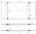
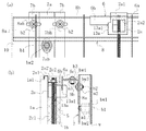
このタイル1、10は、図1〜図3に示すように、横長四辺形板状のタイル本体(プレート部材本体)1aと、該タイル本体1aの裏面側に配する耐火材1bと、該耐火材1bをタイル本体1aの裏面に固定するための固定手段2と、該耐火材1bを裏面に固定したタイル本体1aを建造物の壁面wに、該壁面wに配した支持金具6、6…、26、26…を介して取り付けるための取付手段3、30とで構成したものである。
As shown in FIGS. 1 to 3, the
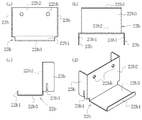
前記タイル本体1aは、図1に示すように、この実施例1では、陶磁器製の大型の四辺形板状部材で構成したものを採用した。このタイル本体1aは、これに代えて、同様なサイズの石材板を採用することも可能である。該タイル本体1aとしては、小型のそれを採用することも不可ではないが、大型のそれの方が好ましい。またこのタイル本体1aは、その平行な二辺である上下辺の端面にそれぞれ二つずつ係止溝1a1、1a1を形成しておく。上下辺の各係止溝1a1、1a1は、相互に上下対応する位置関係で、それぞれ側辺から幅方向約1/5程度の位置に形成しておくこととする。 As shown in FIG. 1, the tile main body 1 a is composed of a large quadrilateral plate-shaped member made of ceramics in the first embodiment. Instead of this, the tile main body 1a can adopt a stone plate of the same size. As the tile body 1a, it is not impossible to adopt a small size, but a large size is preferable. The tile main body 1a has two locking grooves 1a1 and 1a1 on the end surfaces of the upper and lower sides which are two parallel sides. The respective locking grooves 1a1 and 1a1 on the upper and lower sides are formed at positions about 1/5 in the width direction from the side sides in a positional relationship corresponding to the upper and lower sides.
前記固定手段2は、図1〜図9に示すように、タイル本体1aの上下の平行な二辺の内、上辺側に配する二つの上部固定片2a、2aと、下辺側に配する二つの下部固定片2b、2bと、各一対の上部固定片2a及び下部固定片2bの間に配する各一本の連結ボルト2cとで構成する。
As shown in FIGS. 1 to 9, the fixing means 2 includes two
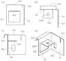
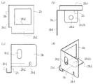
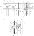
前記上部固定片2aは、図1(a)、図2(a)、図4(a)、(d)及び図7(a)、(d)に示すように、ほぼ四辺形板状の部材であり、図2(a)、図3(a)、図4(a)〜(d)及び図7(a)〜(d)に示すように、その上端に、前記タイル本体1aの上辺の端面に形成した係止溝1a1に挿入係止する係止爪片2a1を形成し、その高さ方向途中に該係止爪片2a1と反対側に突出する連結板2a2を形成したものである。
As shown in FIGS. 1 (a), 2 (a), 4 (a), 4 (d) and 7 (a), 7 (d), the
該係止爪片2a1は、該上部固定片2aの上端から、側面から見て、前側に逆L型に張り出して構成したものであり、該係止爪片2a1は、図3(a)に示すように、該上部固定片2aの前側でこれに平行に垂下する部分を前記タイル本体1aの係止溝1a1に挿入係止するものである。
The locking claw piece 2a1 is configured to project in an inverted L shape from the upper end of the upper
前記連結板2a2は、図4(a)〜(d)及び図7(a)〜(d)に示すように、前記上部固定片2aの中央部分を正面側に四辺形に切り起こし、その両側辺及び前辺を削って、この切り起こしによって生じた四辺形の切欠より小さめに構成し、そのほぼ中央部に連結孔2a2hを開口したものである。なお、該連結板2a2は、同図に示すように、該上部固定片2aの上下辺に平行に、かつその面に直角に切り起こしたものである。
As shown in FIGS. 4 (a) to (d) and FIGS. 7 (a) to (d), the connecting plate 2a2 is formed by cutting the central portion of the
前記下部固定片2bは、図1(a)、図2(b)及び図5(a)、(d)に示すように、ほぼ四辺形板状の部材であり、図2(b)、図3(b)及び図5(a)〜(d)に示すように、その下端に、前記タイル本体1aの下辺の端面に形成した係止溝1a1に挿入係止する係止爪片2b1を形成し、その高さ方向途中に該係止爪片2b1と反対側、即ち、背後側に突出する連結板2b2を形成したものである。
The
該係止爪片2b1は、該下部固定片2bの下端から、側面から見て、前面側にL型に張り出して構成したものであり、該係止爪片2b1は、図3(b)に示すように、該下部固定片2bの前面側でこれに平行に直立する部分を前記タイル本体1aの下辺の係止溝1a1に挿入係止するものである。
The latching claw piece 2b1 is configured to project from the lower end of the lower
前記連結板2b2は、図5(a)〜(d)に示すように、前記下部固定片2bの中央部分を背面側に四辺形に切り起こし、その両側辺及び前辺を削って、この切り起こしによって生じた四辺形の切欠より小さめに構成し、そのほぼ中央部に連結孔2b2hを開口したものである。なお、該連結板2b2は、同図に示すように、該上部固定片2bの上下辺に平行に、かつその面に直角に切り起こしたものである。
As shown in FIGS. 5 (a) to 5 (d), the connecting plate 2b2 is formed by cutting and raising the center portion of the
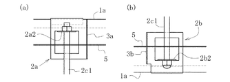
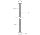
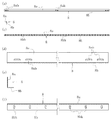
前記連結ボルト2cは、図6に示すように、ボルト部材2c1と、これに螺合するナット部材2c2とからなり、図1(a)〜(c)、図2(a)、(b)、図8(a)〜(c)及び図9(a)〜(c)に示すように、タイル本体1aの上辺側に配した上部固定片2aと下辺側に配した下部固定片2bの連結板2a2、2b2間に配して上部固定片2aと下部固定片2bとを連結すべく使用するものである。
As shown in FIG. 6, the connecting
該連結ボルト2cは、そのボルト部材2c1を下部固定片2bの連結板2b2の連結孔2b2hにその外側(下方)から挿入し、更に上部固定片2aの連結板2a2の連結孔2a2hにその内側(下方)から挿入し、その貫通した部分に前記ナット部材2c2を螺合し締め付ける。これは、逆方向から挿入し、締付固定しても同様なのは云うまでもない。このとき、特に図8(a)及び図9(a)に示すように、前記上部固定片2aは、これに先立って、その係止爪片2a1をタイル本体1aの上辺の係止溝1a1に挿入係止状態にしておき、かつ下部固定片2bはその係止爪片2b1を該タイル本体1aの下辺の係止溝1a1に挿入係止状態としておくのは云うまでもない。こうして固定手段2によるタイル本体1aの固定状態は確実なものとなる。
The connecting
前記取付手段3(30)は、図1〜図5(a)、図7〜図9に示すように、この実施例1では、前記タイル本体1aの上辺に配される二つの上部固定片2a、2aに構成した上部縦向取付板3a、3a(13a、13a)と、下辺に配される下部固定片2b、2bに構成した下部縦向取付板3b、3bと、該上部縦向取付板3a、3a(13a、13a)の上辺に上部開口状態に構成した上向き取付溝3a1、3a1(13a1、13a1)と、該下部縦向取付板3b、3bの下辺に下部開口状態に構成した下向き取付溝3b1、3b1とで構成したものである。
As shown in FIGS. 1 to 5 (a) and FIGS. 7 to 9, the mounting means 3 (30) has two
この取付手段には、壁面wの最上部以外に取り付けるタイル1用である標準タイプの取付手段3と、最上部に取り付けるタイル10用である最上部専用タイプの取付手段30がある。基本的に同様な構成であるが、最上部専用タイプの取付手段30は、図7(a)、(c)、(d)及び図9(a)〜(c)に示すように、標準タイプの取付手段3と上部の構成要素のみが異なる。即ち、最上部専用タイプの取付手段30は、標準タイプの取付手段3の上部の構成要素である上部縦向取付板3a、3aに代えて、これよりもその上辺が低く構成された上部縦向取付板13a、13aを備えた構成となっている。
The attachment means includes a standard type attachment means 3 for the
まず標準タイプの取付手段3から説明する。
前記上部縦向取付板3aは、特に図4に示すように、前記上部固定片2aの一方の側辺で、この実施例では右側辺で、直角に折り曲げて背後側に突き出した板状部材である。該上部固定片2aを前記タイル本体1aに取り付けた状態では、該上部縦向取付板3aは該タイル本体1aの背後側に突き出した状態となる。また該上部縦向取付板3aの上辺の高さは、該上部固定片2aの上辺とほぼ同一の高さである。前記上向き取付溝3a1は、前記し、図4に示すように、該上部縦向取付板3aの上辺の若干先端よりの部位に上部開口状態に形成する。
First, the standard type attachment means 3 will be described.
As shown in FIG. 4, the upper vertical mounting
なお、更にこの実施例1では、該上部縦向取付板3aには、その下部で前記上部固定片2aに近接し、しかし前記連結板2a2の連結孔2a2hよりは、該上部固定片2aから離れた位置に鉄筋5を通過させるための鉄筋穴3a2を開口してある。
Further, in the first embodiment, the upper vertical mounting
前記下部縦向取付板3bは、特に図5に示すように、前記下部固定片2bの一方の側辺で、この実施例1では左側辺で、直角に折り曲げて背後側に突き出した板状部材である。該下部固定片2bを前記タイル本体1aに取り付けた状態では、該下部縦向取付板3bは該タイル本体1aの背後側に突き出した状態となる。また該下部縦向取付板3bの下辺の高さは、該下部固定片2bの下辺より若干高い位置となる。前記下向き取付溝3b1は、前記し、図5に示すように、該下部縦向取付板3bの下辺の若干先端よりの部位に下部開口状態に形成する。この下向き取付溝3b1の下部固定片2bに対する前後方向の位置関係は、前記上向き取付溝3a1と上下対応するように設定する。
As shown particularly in FIG. 5, the lower vertical mounting
なお、更にこの実施例1では、該下部縦向取付板3bには、その下部で前記下部固定片2bに近接し、しかし前記連結板2b2の連結孔2b2hよりは、該下部固定片2bから離れた位置に鉄筋5を通過させるための鉄筋穴3b2を開口してある。
Furthermore, in the first embodiment, the lower vertical mounting
次に最上部専用タイプの取付手段30について説明する。
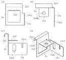
このタイプの取付手段30の上部縦向取付板13aは、特に図7に示すように、前記上部固定片2aの一方の側辺、この実施例1では右側辺で、直角に折り曲げて背後側に突き出した板状部材であり、基本的構成は、標準タイプの上部縦向取付板3aと同様であるが、その上辺が低く構成されている。上辺の高さは、具体的には、図7(a)、(c)でよく分かるように、前記連結板2a2より若干低い位置に設定したものである。この点のみが標準タイプの取付手段3の上部縦向取付板3aと異なり、それ以外は全て同一である。上向き取付溝13a1も、鉄筋穴13a2も、図7に示すように、上部縦向取付板3aのそれらと全く同様に構成してある。
Next, the attachment means 30 of the uppermost exclusive type will be described.
As shown in FIG. 7, the upper vertical mounting
前記したように、最上部専用タイプの取付手段30は、標準タイプのそれと上部縦向取付板13aのみが異なるものであり、下部縦向取付板3bは全く同様であり、各部の符号も同じに付してある。従って説明を繰り返さない。
As described above, the attachment means 30 of the uppermost exclusive type is different from that of the standard type only in the upper vertical mounting
この実施例1のタイル1、10は、前記固定手段2及び取付手段3、30を、前記のようにしてタイル本体1aの裏面側に取り付け、更に鉄筋5、5…を縦横に配した上で、ペースト状耐火材を配し、該タイル本体1aの裏面に接合させ、かつ該固定手段2の上部固定片2a、2a、下部固定片2b、2b、連結板2a2、2a2、2b2、2b2及び連結ボルト2c、2cに絡ませた状態で硬化させて構成したものである。なお、上部固定片2a、2a及び下部固定片2b、2bには、前記連結板2a2、2a2、2b2、2b2を形成するために切り欠いた切欠穴が開口してあるため、ペースト状耐火材はこの切欠穴にも入り込んで絡み良好に結合することになる。なおまた以上の固定手段2及び取付手段3を構成する各部材は、この実施例1では、いずれもステンレススチールで作成したものである。
In the
以上のタイル1、10は、次の手順で製造する。まず標準型のタイル1から説明する。
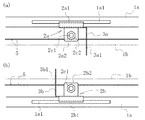
前記タイル本体1aの裏面側に固定手段2を取り付ける。先に説明し、図1〜図3及び図8(a)に示すように、タイル本体1aの上下の平行な二辺の内、上辺側には上部固定片2a、2aを取り付け、下辺側には下部固定片2b、2bを取り付ける。上部固定片2a、2aは、各々その係止爪片2a1、2a1を、該タイル本体1aの上辺の係止溝1a1、1a1に挿入係止して位置決めし、下部固定片2b、2bも同様に、該タイル本体1aの下辺の係止溝1a1、1a1にその係止爪片2b1、2b1を挿入係止することで位置決めする。
The
The fixing means 2 is attached to the back side of the tile body 1a. As described above and shown in FIGS. 1 to 3 and FIG. 8 (a), the
こうした上で、それぞれ上下対応する上部固定片2aと下部固定片2bの連結板2a2、2b2の連結孔2a2h、2b2hに、図8(a)に示すように、前記連結ボルト2cのボルト部材2c1を貫通させ、前記のように、その先端側からナット部材2c2を螺合しかつ締め付けして、各一対の上部固定片2aと下部固定片2bのタイル本体1aへの取付状態を固定する。
Then, as shown in FIG. 8 (a), the bolt member 2c1 of the connecting
この状態で、先に述べ、かつ図8(a)に示すように、該上部固定片2a、2a及び下部固定片2b、2bに構成した取付手段3の上部縦向取付板3a、3a及び下部縦向取付板3b、3bは、それぞれ縦向状態でタイル本体1aの背後方向に延びた状態で配された状態となる。
In this state, as described above and as shown in FIG. 8 (a), the upper vertical mounting
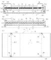
このように固定手段2及び取付手段3を背後に取り付けたタイル本体1aを、図8(a)に示すように、成形箱4内に、その内面に剥離剤を塗布した上で、正面を下にして内装配置する。この成形箱4は、該タイル本体1aと平面寸法形状が一致する内法寸法を有する平面四辺形で、内法高さ寸法が該タイル本体1aの厚みとその裏面に配すべき耐火材の厚みとの合計寸法と一致するように構成したものである。
As shown in FIG. 8 (a), the tile body 1a with the fixing means 2 and the attachment means 3 attached to the back is applied to the inner surface of the
次いで、該成形箱4内に縦横に鉄筋5、5…を配する。詳細には、図1(a)及び図8(c)に示すように、縦方向に4本の鉄筋5、5…を配し、横方向に3本の鉄筋5、5…を配する。横方向の鉄筋5、5、5は、いずれも連結ボルト2c、2cのボルト部材2c1、2c1の上に載せた状態に配する。その内、中央のそれは、単にボルト部材2c1、2c1の上に載置した状態とし、両側のそれは、上部縦向取付板3a、3aの鉄筋穴3a2、3a2又は下部縦向取付板3b、3bの鉄筋穴3b2、3b2中を貫通状態とする。縦方向の4本の鉄筋5、5…は、横方向の3本の鉄筋5、5、5に載せた状態で、かつ定間隔で配する。以上の鉄筋5、5…は必要に応じて針金等でそれら相互を緊締し、更にボルト部材2c1、2c1等と緊締する。
Next, the reinforcing
この後、該成形箱4内にペースト状耐火材を流動装入する。この流動装入は、バイブレータ等を使用して該ペースト状耐火材に振動を加えつつ行う。云うまでもなく、該成形箱4内に均一に該ペースト状耐火材を充填する趣旨である。なおこのペースト状耐火材は、不定形耐火物と称されるものの内、キャスタブル耐火材と称されるものを使用した。
Thereafter, a paste-like refractory material is fluidly charged into the
前記のように、固定手段2及び取付手段3を裏面に取り付けたタイル本体1aを正面を下向きにして装入した成形箱4内に、その上縁まで、該ペースト状耐火材を流動装入し、その上面を均して平坦にする。該ペースト状耐火材の硬化した後に、該成形箱4からタイル本体1aと、その裏面に固設状態となっている硬化した耐火材1bと、該耐火材1bから突出した取付手段3の上部縦向取付板3a、3a及び下部縦向取付板3b、3bとからなる部材、即ち、タイル1を取り出す。図8(b)、(c)は、こうして製造されたタイル1を示している。
As described above, the paste-like refractory material is fluidly charged to the upper edge of the
次に最上部専用タイプのタイル10の製造手順について説明する。
このタイル10は、先に述べたように、以上の標準タイプのタイル1の取付手段3に代えて取付手段30を取り付けた点のみが異なり、それ以外の点は全て同様である。また取付手段3と取付手段30との違いは、前記したように、上部縦向取付板3a、13aの違いのみであり、下部縦向取付板3b、3bは相互に全く同様である。更に上部縦向取付板3aと13aとの違いは、先に説明したその上辺の高さの違いだけである。
Next, the manufacturing procedure of the uppermost
As described above, the
従ってタイル本体1aへの固定手段2の上部固定片2a、2a及び下部固定片2b、2bの取り付け方は、前記したタイル1のためのそれと同様であり、対応する上部固定片2aと下部固定片2bの相互の連結板2a2、2b2間の連結ボルト2cによる連結の仕方も同様である。単に、上部固定片2a、2aとして、最上部専用タイプの上部縦向取付板13aを配したそれを選ぶことのみが異なり、その他は、標準タイプのタイル1の製造手順と同様である。
Therefore, the mounting method of the
しかして、以上のようにしてタイル本体1aの裏面に対応する固定手段2を取り付けると、該固定手段2の上部固定片2a、2a及び下部固定片2b、2bに構成してある取付手段30の上部縦向取付板13a、13a及び下部縦向取付板3b、3bも所定の部位に取り付けられたことになる。
Thus, when the fixing means 2 corresponding to the back surface of the tile main body 1a is attached as described above, the
次いで、このように固定手段2及び取付手段30を裏面に取り付けたタイル本体1aを、標準タイプのそれと同様に、図9(a)に示すように、成形箱4内に、その内面に剥離剤を塗布した上で、正面を下にして内装配置する。この成形箱4は、当然、標準タイプのそれに用いたものと同様である。
Next, the tile main body 1a having the fixing means 2 and the attachment means 30 attached to the back surface in this way is formed in the
次いで、該成形箱4内に縦横に、標準タイプのそれと同様に、鉄筋5、5…を配し、その後、該成形箱4内にペースト状耐火材を流動装入する。全て標準タイプについてと同様に行う。そして該ペースト状耐火材の硬化した後に、該成形箱4からタイル本体1aと、その裏面に固設状態となっている硬化した耐火材1bと、該耐火材1bから突出した取付手段30の上部縦向取付板13a、13a及び下部縦向取付板3b、3bとからなる部材、即ち、タイル10を取り出す。図9(b)、(c)は、こうして製造されたタイル10を示している。
Next, as in the standard type, the reinforcing
次に以上のタイル1、10を用いた壁面構造について説明する。これはトンネル内部の壁面に適用した例に基づいて説明する。
Next, the wall surface structure using the
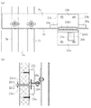
この実施例1の壁面構造は、図10〜図15に示すように、壁面wの最下部以外のエリアには、該壁面wに平行な上向き支持片6a及び下向き支持片6bを備えた支持金具(支持部材)6を縦横に配列固定し、最下部には、同様に該壁面wに平行な上向き支持片16aを備えた支持金具(支持部材)16を横一列に配列固定し、その最上部には、前記最上部専用タイプのタイル10を、その背後の取付手段30を用いて該支持金具6、6の下向き支持片6b、6b及び下方の支持金具6、6の上向き支持片6a、6aに係止することにより、壁面wに取り付け、最上部及び最下部以外の部位には、標準タイプのタイル1を、その背後の取付手段3を用いて、該支持金具6、6の下向き支持片6b、6b及び下方の支持金具6、6の上向き支持片6a、6aに係止することにより、壁面wに取り付ける。また最下部では標準タイプのタイル1を、その背後の取付手段3を用いて、その上辺側は、該支持金具6、6の下向き支持片6b、6bに、下辺側は最下部専用の支持金具16、16の上向き支持片16a、16aに、それぞれ係止することにより、壁面wに取り付ける。こうして壁面wの要取付領域の全てに対応するタイル1又は10取り付ける。タイル1、1間、タイル1、10間及びタイル10、10間の目地には耐火モルタル9を充填する。
As shown in FIGS. 10 to 15, the wall surface structure of the first embodiment has a support bracket provided with an
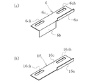
前記支持金具6は、図18(a)に示すように、この実施例1では、長方形板状の金具本体6cと、その先端の右側約半分から直立状態に立ち上げた上向き支持片6aと、左側約半分から垂下させた下向き支持片6bとで構成したものであり、該金具本体6cには、その長さ方向に沿って長い二つの取付孔6ch、6chが開口してある。この支持金具6は、前記したように、最下部以外の全エリアで用いられる標準タイプのものである。また最下部専用の支持金具16は、図18(b)に示すように、長方形板状の金具本体16cと、その先端の右側約半分から直立状態に立ち上げた上向き支持片16aとで構成したものであり、該金具本体16cには、その長さ方向に沿って長い二つの取付孔16ch、16chが開口してある。
As shown in FIG. 18 (a), the
以上の支持金具6、16は、図10〜図15に示すように、壁面wに直接に縦向に取り付けたベース金具7及び該ベース金具7に横向きに取り付けた受け金具8を介して壁面wに取り付ける。
As shown in FIGS. 10 to 15, the
前記ベース金具7は、図16(a)〜(d)に示すように、平面から見て後方に逆U字形に膨らむ金具基部7aと、該金具基部7aの両側板部前端から、これらに直角に折り曲げてそれぞれ外側方向に延長した取付鍔部7b、7bとで構成した長尺部材であり、該金具基部7aの底部には、長さ方向の数カ所にその長さ方向に沿って長い固定長孔7ah、7ah…を開口し、更に該両側の取付鍔部7b、7bには、前記受け金具8、8…を取り付ける間隔に対応させて、同様に長さ方向に長い取付長孔7bh、7bh…を開口してある。
As shown in FIGS. 16 (a) to 16 (d), the base metal fitting 7 has a
前記受け金具8は、図17(a)〜(f)に示すように、直立板部8aと、該直立板部8aの下端から直角に折曲して前方に延長状態に構成した受け板部8bとで構成した、側面から見てL型の長尺板材である。該直立板部8aには、特に図17(a)、(d)に示すように、その両端及び中央に二つずつその長さ方向に長い結合長孔8ah、8ah…を開口し、該受け板部8bには、図17(c)、(f)に示すように、前記支持金具6、16の設置間隔を考慮して、該受け板部8bの長さ方向と直交する方向に長い多数の取付長孔8bh、8bh…を定間隔で開口したものである。
As shown in FIGS. 17 (a) to 17 (f), the receiving
取付対象の壁面wに、複数の前記ベース金具7、7…を、図10に示すように、所定間隔で縦向に配する。この間隔は、該ベース金具7、7…に取り付ける受け金具8、8…に合わせる。該受け金具8は、前記のように、その中央部及び両端に二個ずつ結合用の結合長孔8ah、8ahを開口しているので、該ベース金具7、7…は、該間隔に対応する横方向の間隔で配する訳である。
As shown in FIG. 10, a plurality of the
該ベース金具7は、前記し、図11(a)、(b)、図12(a)、(b)、図14(a)、(b)及び図15(a)、(b)に示すように、縦向状態で壁面wにその金具基部7aの底部外面を対面させ、予め該壁面wに下穴を開け、該下穴に挿入固定し、ワッシャbw1を外装してあるアンカーボルトb1、b1…を該底部に開口してある固定長孔7ah、7ah…に貫通させ、該金具基部7aの底部の外面側から該アンカーボルトb1、b1…にワッシャbw2、bw2…を配した上で、ナットn1、n1…を螺合締め付けし、該ベース金具7を壁面wに固定する。なお、該下穴は、該ベース金具7の固定長孔7ah、7ah…の間隔に対応して開口しておくべきなのは云うまでもない。
The
前記した横方向の間隔で壁面wの所要エリアに必要数のベース金具7、7…を縦向に固設した後、該ベース金具7、7…には、図10に示すように、受け金具8、8…を、取付対象のタイル1、10の縦方向寸法に対応する間隔で取り付ける。
After the necessary number of
該受け金具8は、図11(a)、(b)〜図15(a)、(b)に示すように、横向きにして、その直立板部8aを、前記ベース金具7の取付鍔部7b、7bに当接させ、その取付長孔7bh、7bhと該直立板部8aの結合長孔8ah、8ahとを対応させて、両者にワッシャbw3を挟んでボルトb2を貫通させ、ナットn2を螺合して締め付け、両者を結合固定する。なお、該受け金具8、8…は、図11(a)、(b)及び図12(a)、(b)に示すように、壁面wの取付エリアの最上部では、受け板部8bが直立板部8aの上部側に位置するように向きを決めて取り付け、最上部以外では、図11(a)、(b)、図13(a)、(b)及び図14(a)、(b)に示すように、受け板部8bが直立板部8aの下部側に位置するように向きを決めて取り付ける。
As shown in FIGS. 11 (a), (b) to 15 (a), (b), the receiving
前記支持金具6は、その金具本体6cを、該受け金具8の受け板部8bに、前者の取付孔6ch、6chと後者の取付長孔8bh、8bhとを一致させ、ボルトb3をワッシャbw4を挟みつつ該取付長孔8bh、8bhと取付孔6ch、6chとに挿入し、ナットn3を螺合し締め付けることで取付固定する。該支持金具6は、取付対象のタイル1、10の取付時の配列状態に対応して配置する。即ち、その場合の取付手段3、30の上部縦向取付板3a、13a及び下部縦向取付板3bの位置に対応させて取り付けておく。
The
こうして必要な領域に支持金具6、6…を取り付けた後は、図10に示すように、タイル1、10を順次取り付ける。タイル10は、前記のように、壁面wの取付エリアの最上部に取り付け、タイル1はそれ以外の全ての部位に取り付ける。取り付け方は、基本的には、いずれも同様である。
After attaching the
タイル1、10は、図11(a)、(b)〜図15(a)、(b)に示すように、取付手段3の上部縦向取付板3a、3a、13a、13aの上向き取付溝3a1、3a1、13a1、13a1に、前記受け金具8に取り付けられた支持金具6の下向き支持片6bを深く進入させるべく引き上げ、下部を十分上昇させた上で、取付手段3の下部縦向取付板3b、3bの下向き取付溝3b1、3b1に、下方の支持金具6の上向き支持片6a、6aを進入させ、これにより、上部縦向取付板3a、3a、13a、13aと上方の支持金具6の下向き支持片6b、6b及び下部縦向取付板3b、3bと下方の支持金具6の上向き支持片6a、6aとで壁面wに取付状態とする。これを、壁面wの取付領域の全てで繰り返せばタイル1、10の取付は完了する。
As shown in FIGS. 11A, 11B, 15A, and 15B, the
この後は、タイル1、1間、タイル1、10間、タイル10、10間の目地に耐火モルタル9を充填する。こうして壁面wへの耐火材1bを備えたタイル1、10の取付は完了である。
Thereafter, the joints between the
<実施例2>
この実施例2は、裏面に板状の耐火材21bを固定したタイル(プレート部材)21、31及び該タイル21、31を用いた壁面構造に関する。
<Example 2>
The second embodiment relates to tiles (plate members) 21 and 31 having a plate-like
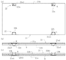
このタイル21、31は、図19〜図23に示すように、横長四辺形板状のタイル本体(プレート部材本体)21aと、該タイル本体21aの裏面側に配する板状の耐火材21bと、該耐火材21bをタイル本体21aの裏面に固定するための固定手段22と、該耐火材21bを裏面に固定したタイル本体21aを建造物の壁面wに、該壁面wに配した支持金具(支持部材)26、26…を介して取り付けるための取付手段23、33とで構成したものである。
As shown in FIGS. 19 to 23, the
前記タイル本体21aは、図19に示すように、この実施例2では、実施例1のタイル本体1aと全く同様の陶磁器製の大型の四辺形板状部材で構成したものを採用した。このタイル本体21aは、実施例1のタイル本体1aと同様に、これに代えて、同様なサイズの石材板を採用することも可能である。またこのタイル本体21aも、実施例1のタイル本体1aと同様に、その平行な二辺である上下辺の端面にそれぞれ二つずつ係止溝21a1、21a1が形成してある。
As shown in FIG. 19, the tile
前記耐火材21bは、必要な耐火性能を保持しうる耐火素材で構成された板状部材であり、裏面から見てタイル本体21aと同一寸法の四辺形に構成された部材である。その厚みは、上記のように、耐火・耐熱性能との関係で、タイル本体21aより若干厚みの厚いものとなっている。
The
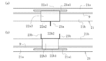
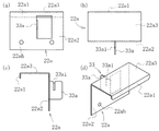
前記固定手段22は、図19〜図26に示すように、前記タイル本体21aの上下の平行な二辺の内、上辺側で該耐火材21bを固定すべく配する二つの上部固定片22a、22aと、下辺側で該耐火材21bを固定すべく配する二つの下部固定片22b、22bとで構成する。
As shown in FIGS. 19 to 26, the fixing means 22 includes two
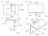
前記上部固定片22aは、図19、図20(a)、図21(a)、図22、図23、図24及び図26に示すように、四辺形の板状部材である背面板22a2とその上端から直角に前方に延びる抑え板22a3とからなる、側面から見てほぼ逆L型の部材であり、該抑え板22a3の前端から前記タイル本体21aの上辺の端面に形成した係止溝21a1に挿入係止する係止爪片22a1を形成し、背面板22a2には、耐火材21bにねじ込むビス用の二つのビス孔22ah、22ahを開口してある。
As shown in FIGS. 19, 20 (a), 21 (a), 22, 23, 24, and 26, the
前記抑え板22a3の係止爪片22a1側への張出寸法は、前記耐火材21bの厚み寸法、タイル本体21aの背面からその係止溝21a1までの寸法及びその間に配する耐火モルタル9の厚み寸法を加えたそれに対応する寸法とする。また前記係止爪片22a1は、図19、図20(a)、図21(a)、図22、図23(a)、図24及び図26に示すように、前記上部固定片22aの前面側でその背面板22a2に平行に垂下し、前記のように、前記タイル本体21aの係止溝21a1に挿入係止するようになっている。
The projecting dimension of the holding plate 22a3 toward the locking claw piece 22a1 includes the thickness of the
前記下部固定片22bは、図19、図20(b)、図21(b)、図22(a)及び図25に示すように、四辺形の板状部材である背面板22b2とその下端から直角に前方に延びる受け板22b3とからなる、側面から見てL型の部材であり、該受け板22b3の前端から前記タイル本体21aの下辺の端面に形成した係止溝21a1に挿入係止する係止爪片22b1を形成し、背面板22b2には、耐火材21bにねじ込むビス用の二つのビス孔22bh、22bhを開口してある。
As shown in FIGS. 19, 20 (b), 21 (b), 22 (a), and 25, the
前記受け板22b3の係止爪片22b1側への張出寸法は、全く前記抑え板22a3のそれと同様であり、前記耐火材21bの厚み寸法、タイル本体21aの背面からその係止溝21a1までの寸法及びその間に配する耐火モルタル9の厚み寸法を加えたそれに対応する寸法とする。また前記係止爪片22b1は、図19、図20(b)、図21(b)、図22(a)及び図25に示すように、前記下部固定片22bの前面側でその背面板22b2に平行に直立し、前記のように、前記タイル本体21aの下辺の係止溝21a1に挿入係止するようになっている。
The protruding dimension of the receiving plate 22b3 toward the locking claw piece 22b1 is completely the same as that of the holding plate 22a3. The thickness dimension of the
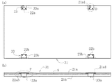
前記取付手段23(33)は、図19〜図26に示すように、この実施例2では、前記タイル本体21aの上辺に配される二つの上部固定片22a、22aに各々一つずつ構成した上部縦向取付板23a(33a)と、下辺に配される下部固定片22b、22bに一対ずつ構成した下部縦向取付板23b、23bと、該上部縦向取付板23a(33a)の上辺に上部開口状態に構成した上向き取付溝23a1(33a1)と、該下部縦向取付板23b、23bの下辺に下部開口状態に構成した下向き取付溝23b1とで構成したものである。
As shown in FIGS. 19 to 26, the attachment means 23 (33) is configured by two
この取付手段には、壁面wの最上部以外に取り付けるタイル21用である標準タイプの取付手段23と、最上部に取り付けるタイル31用である最上部専用タイプの取付手段33がある。基本的に同様な構成であるが、最上部専用タイプのそれは、図22及び図26に示すように、標準タイプの取付手段23とは上部の構成要素のみが異なる。即ち、最上部専用タイプの取付手段33は、標準タイプの取付手段23の上部の構成要素である上部縦向取付板23a、23aに代えて、これよりもその上辺が低く構成された上部縦向取付板33a、33aを備えた構成となっている。
The attachment means includes a standard type attachment means 23 for the
まず標準タイプの取付手段23から説明する。
前記上部縦向取付板23aは、特に図24に示すように、前記上部固定片22aの背面板22a2のほぼ中央から背後方向に突き出した板状部材である。より詳細には、該上部縦向取付板23aは、該背面板22a2を、縦辺の一方が該背面板22a2のほぼ中央側に位置することとなるように、四辺形の上下辺及び他の側辺に沿って切り抜き、中央側の辺で切り抜かれた四辺形板状部を、直角に起こして構成したものである。該上部固定片22aを前記のように、前記タイル本体21a及び耐火材21bの背後に取り付けた状態では、該上部縦向取付板23aは該タイル本体21a及び耐火材21bの背後側に突き出した状態となる。また該上部縦向取付板23aの上辺の高さは、該タイル本体21a及び耐火材21bの上辺とほぼ同一の高さである。前記上向き取付溝23a1は、前記し、図24に示すように、該上部縦向取付板23aの上辺の若干背面板22a2寄りの部位に上部開口状態に形成する。
First, the standard type attachment means 23 will be described.
As shown in FIG. 24 in particular, the upper vertical mounting
また前記下部縦向取付板23b、23bは、特に図25に示すように、前記下部固定片22bの両側辺で、直角に折り曲げて背面側に突き出した板状部材である。該下部固定片22bを前記タイル本体21a及び耐火材21bの背後に取り付けた状態では、該下部縦向取付板23b、23bは該タイル本体21a及び耐火材21bの背後側に突き出した状態となる。また該下部縦向取付板23b、23bの下辺の高さは、該下部固定片22bの下辺より若干高い位置となる。前記下向き取付溝23b1は、前記し、図25に示すように、該下部縦向取付板23b、23bの下辺の若干背面板22b2寄りの部位に下部開口状態に形成する。この下向き取付溝23b1の下部固定片22bに対する背後方向の位置関係は、前記上向き取付溝23a1と上下対応するように設定する。
The lower vertical mounting
次に最上部専用タイプの取付手段33について説明する。
このタイプの取付手段33の上部縦向取付板33aは、特に図26に示すように、前記上部固定片22aの背面板22a2のほぼ中央から背後方向に突き出した、標準タイプのそれと同様の板状部材である。より詳細には、該上部縦向取付板33aは、該背面板22a2を、縦辺の一方が該背面板22a2のほぼ中央側に位置することとなるように、四辺形の上下辺及び他の側辺に沿って切り抜き、中央側の辺で切り抜かれた四辺形板状部を、直角に起こして構成したものであり、この点も標準タイプの上部縦向取付板23aと同様である。該上部固定片22aを前記のように、前記タイル本体21a及び耐火材21bの背後に取り付けた状態では、該上部縦向取付板33aは該タイル本体21a及び耐火材21bの背後側に突き出した状態となり、この点も当然標準タイプの上部縦向取付板23aと同様である。該上部縦向取付板33aの上辺の高さは、該タイル本体21a及び耐火材21bの上辺より若干低い位置となっており、この点のみが標準タイプの上部縦向取付板23aと異なる。前記上向き取付溝33a1は、前記し、図26に示すように、該上部縦向取付板33aの上辺の若干背面板22a2寄りの部位に上部開口状態に形成する。この位置関係及び深さは、上向き取付溝23a1と同様である。
Next, the uppermost dedicated type attachment means 33 will be described.
As shown in FIG. 26, the upper vertical mounting
前記したように、以上の最上部専用タイプの取付手段33は、標準タイプのそれと上部縦向取付板33aのみが異なり、下部縦向取付板23bは標準タイプのそれと全く同様であり、各部の符号も同様に付してある。従ってこれも説明を繰り返さない。
なお、以上の固定手段22及び取付手段23、33を構成する上部固定片22a、下部固定片22b及び上部縦向取付板23a等の全部材は、この実施例2では、ステンレススチールで構成したものである。
As described above, the uppermost dedicated mounting means 33 is different from that of the standard type only in the upper vertical mounting
In the second embodiment, all members such as the
しかしてこの実施例2のタイル21、31の内、標準タイプのタイル21は、次の手順で構成することができる。
図19に示すように、前記タイル本体21aの裏面に前記耐火材21bを接合し、前記のように、該タイル本体21a及び該耐火材21bの上辺側の二箇所に、標準タイプの取付手段23の上部縦向取付板23aを配した上部固定片22a、22aを配し、下辺側の二箇所に下部固定片22b、22bを配する。
Of the
As shown in FIG. 19, the
上部固定片22a、22aの背面板22a2は、それぞれ該耐火材21bの背面上部の対応する部位に接合し、図19(a)、(b)、図20(a)及び図21(a)に示すように、抑え板22a3、22a3を該耐火材21b及び該タイル本体21aの上辺端面に接合する。同時に、同図に示すように、該抑え板22a3、22a3の先端の係止爪片22a1をそれぞれタイル本体21aの上辺の係止溝21a1、21a1に挿入係止する。
The back plates 22a2 of the
更に図19(a)、(c)、図20(b)及び図21(b)に示すように、下部固定片22b、22bの背面板22b2は、それぞれ該耐火材21bの背面下部の対応する部位に接合し、受け板22b3、22b3を該耐火材21b及び該タイル本体21aの下辺端面に接合する。同時に、同図に示すように、該受け板22b3、22b3の先端の係止爪片22b1をそれぞれタイル本体21aの下辺の係止溝21a1、21a1に挿入係止する。
Further, as shown in FIGS. 19 (a), 19 (c), 20 (b) and 21 (b), the back plate 22b2 of the
以上の状態で、図19(a)及び図20(a)、(b)に示すように、前記上部固定片22a、22a及び前記下部固定片22b、22bの各背面板22a2、22a2、22b2、22b2の各二つのビス孔22ah、22ah、22bh、22bhを通じてビスをねじ込み、その取付状態を固定する。
In the above state, as shown in FIGS. 19 (a), 20 (a), and 20 (b), the back plate 22a2, 22a2, 22b2, each of the
なお、前記タイル本体21aと前記耐火材21bとは、相互を前記のように接合する場合に、両者間に耐火モルタル9を配して接合固定しておく。この接合固定は、以上の上部固定片22a、22a及び下部固定片22b、22bの取り付けにより、より確実なものとなる。
When the tile
壁面wの最上部に取り付ける最上部専用のタイル31もタイル21と同様の手順で作成する。
図22に示すように、前記タイル本体21aの背面に前記耐火材21bを接合し、該タイル本体21a及び該耐火材21bの上辺側の二箇所に、最上部専用の取付手段33の上部縦向取付板33aを配した上部固定片22a、22aを配し、下辺側の二箇所に下部固定片22b、22bを配する。以上のように、該タイル本体21a及び該耐火材21bの上辺側の二箇所に、最上部専用の取付手段33の上部縦向取付板33aを配した上部固定片22a、22aを配する点のみが、前記標準タイプのタイル21と異なり、その他の点は全て同一である。従ってその他の説明は省略する。
The
As shown in FIG. 22, the
次に以上のタイル21、31を用いた壁面構造について説明する。これもトンネル内部の壁面wに適用した例に基づいて説明する。
Next, the wall surface structure using the
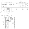
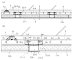
この実施例2の壁面構造も、実施例1のタイル1、10を用いた壁面構造と基本的には同様である。壁面wの最上部及び最下部以外のエリアには、該壁面wに平行な二つの上向き支持片26a、26a及びその間の一つの下向き支持片26bを備えた支持金具(支持部材)26を縦横に配列固定し、最上部には、同様に該壁面wに平行な一つの支持片36aを備えた支持金具(支持部材)36を該支持片36aを下向きにして横一列に配列固定し、更に最下部には、同様に、該支持金具36を、その支持片36aを該壁面wに平行にかつ上向きにして横一列に配列固定し、その最上部には、前記最上部専用タイプのタイル31を、その背後の取付手段33を用いて対応する支持金具36の下向きの支持片36a及び対応する下方の支持金具26の上向き支持片26a、26aに係止することにより、壁面wに取り付け、最上部以外の部位には、標準タイプのタイル21を、その背後の取付手段23を用いて、上部は、該支持金具26の下向き支持片26bに係止し、下部は下方の支持金具26の上向き支持片26a又は最下部専用の支持金具36の上向きにした支持片36aに係止することにより、壁面wに取り付ける。こうして壁面wの要取付領域の全てに対応するタイル21、31を取り付ける。タイル21、21間、タイル21、31間及びタイル31、31間の目地には耐火モルタル9を充填する。
The wall surface structure of the second embodiment is basically the same as the wall surface structure using the
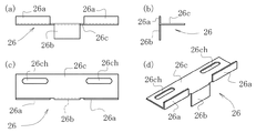
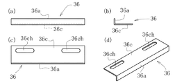
壁面wの最上部及び最下部以外に用いる支持金具26は、図31に示すように、この実施例2では、長方形板状の金具本体26cと、その先端の左右の約1/3の部分から直立状態に立ち上げた上向き支持片26a、26aと、中央の1/3の部分から垂下させた下向き支持片26bとで構成したものであり、該金具本体26cには、その長さ方向に沿って長い二つの取付孔26ch、26chが開口してある。この支持金具26は、前記したように、壁面wの取り付けエリアの最上部及び最下部以外の全エリアで用いられる標準タイプのものである。また最上部及び最下部専用の支持金具36は、図32に示すように、長方形板状の金具本体36cと、その先端から直角に配した、最上部で使用する場合は下向きに、最下部で使用する場合は上向きにする、支持片36aとで構成したものであり、該金具本体36cには、その長さ方向に沿って長い二つの取付孔36ch、36chが開口してある。
As shown in FIG. 31, the
以上の支持金具26、36は、図27〜図30に示すように、実施例1で説明した、壁面wの前面に直接に縦向に取り付けるベース金具7及び該ベース金具7に横向きに取り付けた受け金具8を介して壁面wに取り付ける。
As shown in FIGS. 27 to 30, the
標準タイプの支持金具26は、図27及び図29に示すように、最上部及び最下部以外の全ての部位で、その金具本体26cを、前記受け金具8の受け板部8bに、前者の取付孔26ch、26chと後者の取付長孔8bh、8bhとを一致させ、ボルトb3をワッシャbw4を挟みつつ該取付長孔8bh、8bhと取付孔26ch、26chとに挿入し、ナットn3を螺合し締め付けることで取付固定する。
As shown in FIGS. 27 and 29, the standard-type support metal fitting 26 has the metal
最上部及び最下部専用の支持金具36は、最上部では、図27及び図28に示すように、その金具本体36cを、前記受け金具8の受け板部8bに、前者の取付孔36ch、36chと後者の取付長孔8bh、8bhとを一致させ、ボルトb3をワッシャbw4を挟みつつ該取付長孔8bh、8bhと取付孔36ch、36chとに挿入し、ナットn3を螺合し締め付けることで取付固定する。なお、ここでは、該支持金具36の金具本体36cは、同図に示すように、該受け金具8の受け板部8bの下面側に接合して固定している。もっとも上面側に固定しても不都合ではない。
As shown in FIGS. 27 and 28, the uppermost and lowermost
該支持金具36は、最下部では、図27及び図30に示すように、その金具本体36cを、前記受け金具8の受け板部8bの上面側に接合して、最上部で該受け金具8に取り付けたと同様に取り付けて固定する。
As shown in FIG. 27 and FIG. 30, the support metal fitting 36 is joined to the upper surface side of the receiving
なお、以上の支持金具26、26…、36、36…は、云うまでもなく、取付対象のタイル21、31の取付時の配列状態に対応して配置する。即ち、その場合の取付手段23、33の上部縦向取付板23a、33a及び下部縦向取付板23bの位置に対応させて取り付けておくものである。
Needless to say, the
こうして必要な領域に支持金具26、26…、36、36…を取り付けた後は、実施例1について示した図10の配列と同様に、タイル21、31を順次取り付ける。タイル31は、前記のように、壁面wの取付エリアの最上部にのみ取り付け、タイル21はそれ以外の全ての部位に取り付ける。取り付け方は、基本的には、いずれも同様である。
After attaching the
取り付けエリアの最上部及び最下部以外の部位では、タイル21は、図27、図29及び図33に示すように、取付手段23の上部縦向取付板23aの上向き取付溝23a1に、前記受け金具8に取り付けられた支持金具26の下向き支持片26bを深く進入させるべく引き上げ、下部を十分上昇させた上で、取付手段23の二つの下部縦向取付板23b、23bの下向き取付溝23b1、23b1に、下方の支持金具26の二つの上向き支持片26a、26aを進入させ、これにより、上部縦向取付板23aと上方の支持金具26の下向き支持片26b及び下部縦向取付板23b、23bと下方の支持金具26の上向き支持片26a、26aとで壁面wに取付状態とする。これを、壁面wの最上部及び最下部を除く取付領域の全てで繰り返す。
At portions other than the uppermost part and the lowermost part of the attachment area, the
取付エリアの最上部では、タイル31は、図27及び図28に示すように、取付手段33の上部縦向取付板33aの上向き取付溝33a1に、前記受け金具8に配した支持金具36の下向きにした支持片36aを深く進入させるべく引き上げ、下部を十分上昇させた上で、取付手段33の二つの下部縦向取付板23b、23bの下向き取付溝23b1、23b1に、下方の支持金具26の二つの上向き支持片26a、26aを進入させ、これにより、上部縦向取付板33aと上方の支持金具36の下向きにした支持片36a及び下部縦向取付板23b、23bと下方の支持金具26の上向き支持片26a、26aとで壁面wに取付状態とする。これを、壁面wの最上部の取付領域の全てで繰り返す。
In the uppermost part of the mounting area, the
取付エリアの最下部では、タイル21は、図27、図29、図30及び図33に示すように、取付手段23の上部縦向取付板23aの上向き取付溝23a1に、前記受け金具8に取り付けられた支持金具26の下向き支持片26bを深く進入させるべく引き上げ、下部を十分上昇させた上で、取付手段23の二つの下部縦向取付板23b、23bの下向き取付溝23b1、23b1に、下方の支持金具36の上向きにした支持片36aを進入させ、これにより、上部縦向取付板23aと上方の支持金具26の下向き支持片26b及び下部縦向取付板23b、23bと下方の支持金具36の上向きにした支持片36aとで壁面wに取付状態とする。これを、壁面wの最下部の取付領域の全てで繰り返す。
At the lowermost part of the mounting area, the
なお、以上に於いて、実施例1の場合も同様であるが、下部縦向取付板23b、23bと下方の支持金具26の上向き支持片26a、26a又は支持金具36の上向きにした支持片36aとを結合した後、上方の支持金具26、36の位置決めをしながら、上部縦向取付板23aとの結合を図るような手順の取り付け方をしても不都合ではない。この場合は、順次下方からタイル21を取り付けて行き、最後にタイル31を取り付けることになる。
In the above description, the same applies to the case of the first embodiment. However, the
この後は、タイル21、21間、タイル21、31間、タイル31、31間の目地に耐火モルタル9を充填する。こうして壁面wへの耐火材21bを備えたタイル21、31の取付は完了である。
Thereafter, the joints between the
1 タイル
1a タイル本体(プレート部材本体)
1a1 係止溝
1b 耐火材
2 固定手段
2a 上部固定片
2a1 係止爪片
2a2 連結板
2a2h 連結孔
2b 下部固定片
2b1 係止爪片
2b2 連結板
2b2h 連結孔
2c 連結ボルト
2c1 ボルト部材
2c2 ナット部材
3 取付手段
3a 上部縦向取付板
3a1 上向き取付溝
3a2 鉄筋穴
3b 下部縦向取付板
3b1 下向き取付溝
3b2 鉄筋穴
4 成形箱
5 鉄筋
6 支持金具(支持部材)
6a 上向き支持片
6b 下向き支持片
6c 金具本体
6ch 取付孔
7 ベース金具
7a 金具基部
7ah 固定長孔
7b 取付鍔部
7bh 取付長孔
8 受け金具
8a 直立板部
8ah 結合長孔
8b 受け板部
8bh 取付長孔
9 耐火モルタル
10 タイル
13a 上部縦向取付板
13a1 上向き取付溝
13a2 鉄筋穴
16 支持金具(支持部材)
16a 上向き支持片
16c 金具本体
16ch 取付孔
21 タイル(プレート部材)
21a タイル本体(プレート部材本体)
21a1 係止溝
21b 耐火材
22 固定手段
22a 上部固定片
22a1 係止爪片
22a2 背面板
22a3 抑え板
22ah ビス孔
22b 下部固定片
22b1 係止爪片
22b2 背面板
22b3 受け板
22bh ビス孔
23 取付手段
23a 上部縦向取付板
23a1 上向き取付溝
23b 下部縦向取付板
23b1 下向き取付溝
26 支持金具(支持部材)
26a 上向き支持片
26b 下向き支持片
26c 金具本体
26ch 取付孔
30 取付手段
31 タイル(プレート部材)
33 取付手段
33a 上部縦向取付板
33a1 上向き取付溝
36 支持金具(支持部材)
36a 支持片
36c 金具本体
36ch 取付孔
b1 アンカーボルト
b2 ボルト
b3 ボルト
bw1 ワッシャ
bw2 ワッシャ
bw3 ワッシャ
bw4 ワッシャ
n1 ナット
n2 ナット
n3 ナット
w 壁面
1 tile 1a tile body (plate member body)
6a
16a
21a Tile body (plate member body)
21a1 Locking
26a
33 Mounting means 33a Upper vertical mounting plate 33a1 Upward mounting
Claims (5)
該プレート部材本体の裏面側に配する耐火材と、
該耐火材をプレート部材本体の裏面に固定するための固定手段と、
該耐火材を裏面に固定したプレート部材本体を建造物の壁面に、これに配した支持部材を介して取り付けるための取付手段と、
で構成したプレート部材。 A quadrilateral plate member body,
A refractory material disposed on the back side of the plate member body;
Fixing means for fixing the refractory material to the back surface of the plate member body;
An attachment means for attaching the plate member main body with the refractory material fixed to the back surface to the wall surface of the building via a support member disposed on the wall,
Plate member composed of
前記取付手段を、該固定手段の各固定片の一部から該耐火材の裏面より背後方向に突出させた上下一対以上の縦向取付板と、該上下一対以上の縦向取付板の内の、上方のそれの上辺に上部開口状態に構成した上向き取付溝及び下方のそれの下辺に下部開口状態に構成した下向き取付溝とで構成した請求項1のプレート部材。 The fixing means includes a locking claw piece inserted and locked in each of one or more locking grooves formed on two parallel sides of the plate member body, and a connection configured in a direction parallel to the side where the locking grooves are formed. A pair of fixing pieces provided with a plate, and a connecting bolt for connecting the connecting plates of the pair of fixing pieces and securing the insertion locking state of the locking claw pieces into the corresponding locking grooves; When the required amount of paste-like refractory material is applied to the back side of the plate member body and cured, the refractory material that is entangled with the fixing means can be fixed to the back surface of the plate member body. ,
The mounting means includes a pair of upper and lower vertical mounting plates that protrude backward from the rear surface of the refractory material from a part of each fixing piece of the fixing means, and a pair of the vertical mounting plates of the upper and lower vertical mounting plates. 2. A plate member according to claim 1, comprising an upward mounting groove formed in an upper opening state on the upper side of the upper part and a downward mounting groove formed in a lower opening state on the lower side of the lower part thereof.
前記取付手段を、該固定手段の各固定片の一部から該耐火材の裏面より背後方向に突出させた上下一対以上の縦向取付板と、該上下一対以上の縦向取付板の内の、上方のそれの上辺に上部開口状態に構成した上向き取付溝及び下方のそれの下辺に下部開口状態に構成した下向き取付溝とで構成した請求項1のプレート部材。 A locking claw piece for inserting and locking the fixing means in each of one or more locking grooves formed on two parallel sides of the plate member body, and the locking claw piece, It is composed of a pair of one or more fixing pieces that hold the refractory material bonded and fixed to the back surface of the plate member main body in the state of being inserted into and locked into the locking groove on the plate member main body side,
The mounting means includes a pair of upper and lower vertical mounting plates projecting from a part of each fixing piece of the fixing means in a rearward direction from the rear surface of the refractory material, and a pair of the upper and lower vertical mounting plates. 2. A plate member according to claim 1, comprising an upward mounting groove formed in an upper opening state on the upper side of the upper part and a downward mounting groove formed in a lower opening state on the lower side of the lower part thereof.
平行な異なる辺に配した対応する固定片相互の連結板を連結ボルトで結合して、該相互の固定片に配してある係止爪片の係止溝への挿入係止状態を確保した後、
該プレート部材本体と平面寸法形状が一致する内法寸法を有する成形箱に、該一対以上の固定片を取り付けたプレート部材本体を正面を下向きにして装入し、
その後、ペースト状耐火材を該成形箱内のプレート部材本体の裏面側に前記取付手段を構成する係止片の直下まで充填し、
該ペースト状耐火材を硬化させた後に取り出すことによる請求項2のプレート部材の製造方法。 A locking claw piece of one or more fixed pieces is inserted and locked in each of one or more locking grooves formed on two parallel sides of the quadrilateral plate-like plate member body,
The connecting plates of the corresponding fixed pieces arranged on different parallel sides are connected with connecting bolts to secure the insertion locking state of the locking claw pieces arranged on the fixed pieces to the locking grooves. rear,
Inserting the plate member main body with the pair of fixed pieces attached thereto into a molding box having an internal dimension that matches the planar dimension shape with the plate member main body with the front facing downward,
Then, the paste-like refractory material is filled to the back side of the plate member main body in the molding box up to just below the locking piece constituting the attachment means,
The manufacturing method of the plate member of Claim 2 by taking out after hardening this paste-like refractory material.
請求項2又は3の複数のプレート部材を、その各々の取付手段の下方の縦向取付板の下向き取付溝に対応する位置の支持部材の上向き支持片を挿入させ、上方の縦向取付板の上向き取付溝に対応する位置の支持部材の下向き支持片を挿入させて該壁面に縦横に配列固定し、
該壁面に背面に耐火材を配したプレート部材によって構成した壁面構造。 A support member provided with an upward support piece and a downward support piece parallel to the wall surface is arranged and fixed vertically and horizontally on the wall surface of the building,
The plurality of plate members according to claim 2 or 3 are inserted with an upward support piece of a support member at a position corresponding to the downward mounting groove of the vertical mounting plate below each mounting means, and the upper vertical mounting plate Insert the downward support piece of the support member at a position corresponding to the upward mounting groove, and fix the arrangement vertically and horizontally on the wall surface,
A wall surface structure constituted by a plate member having a refractory material on the back surface thereof.
Priority Applications (1)
| Application Number | Priority Date | Filing Date | Title |
|---|---|---|---|
| JP2007341573A JP4943317B2 (en) | 2007-12-30 | 2007-12-30 | Plate member, method for manufacturing the same, and wall surface structure constituted by the plate member |
Applications Claiming Priority (1)
| Application Number | Priority Date | Filing Date | Title |
|---|---|---|---|
| JP2007341573A JP4943317B2 (en) | 2007-12-30 | 2007-12-30 | Plate member, method for manufacturing the same, and wall surface structure constituted by the plate member |
Publications (2)
| Publication Number | Publication Date |
|---|---|
| JP2009161970A true JP2009161970A (en) | 2009-07-23 |
| JP4943317B2 JP4943317B2 (en) | 2012-05-30 |
Family
ID=40964887
Family Applications (1)
| Application Number | Title | Priority Date | Filing Date |
|---|---|---|---|
| JP2007341573A Active JP4943317B2 (en) | 2007-12-30 | 2007-12-30 | Plate member, method for manufacturing the same, and wall surface structure constituted by the plate member |
Country Status (1)
| Country | Link |
|---|---|
| JP (1) | JP4943317B2 (en) |
Cited By (6)
| Publication number | Priority date | Publication date | Assignee | Title |
|---|---|---|---|---|
| JP5419311B1 (en) * | 2013-06-19 | 2014-02-19 | 株式会社クリーンシステムサービス | Exterior sandwich panel installation method |
| JP2015055074A (en) * | 2013-09-11 | 2015-03-23 | 大成建設株式会社 | Joining structure |
| JP2018040246A (en) * | 2017-11-14 | 2018-03-15 | 大成建設株式会社 | Connection structure and connection method |
| JP2018109338A (en) * | 2017-01-06 | 2018-07-12 | Toto株式会社 | Method of fixing inorganic plate, fixing member for use in the fixing method, and structure obtained by the fixing method |
| CN111305420A (en) * | 2019-12-20 | 2020-06-19 | 华东建筑设计研究院有限公司 | Connection structure and precast concrete wallboard system |
| CN116001206A (en) * | 2023-03-28 | 2023-04-25 | 四川新升包装科技有限责任公司 | Injection mold for plastic container |
Families Citing this family (1)
| Publication number | Priority date | Publication date | Assignee | Title |
|---|---|---|---|---|
| KR101276164B1 (en) * | 2013-02-06 | 2013-06-18 | 주식회사 기산엔지니어링 | A falling rock prevention pence with open type |
Citations (7)
| Publication number | Priority date | Publication date | Assignee | Title |
|---|---|---|---|---|
| JPS61147825A (en) * | 1984-12-18 | 1986-07-05 | Toyota Motor Corp | Method for dispersing powdery and granular material of metallic compound into porous body |
| JPH07229267A (en) * | 1994-02-17 | 1995-08-29 | Rio:Kk | Mounting method for tile |
| JP2001073531A (en) * | 1999-09-02 | 2001-03-21 | Horyo Sangyo Kk | Mounting structure of tiling panel |
| JP2001115786A (en) * | 1999-10-21 | 2001-04-24 | Misawa Ceramics Corp | Tile unit base material and tilt unit for tunnel interior finishing, and structure and method for mountig tile unit |
| JP2001193395A (en) * | 2000-01-07 | 2001-07-17 | Kurosaki Harima Corp | Mounting structure for heat insulating refractory |
| JP2003278497A (en) * | 2002-03-22 | 2003-10-02 | Maeda Corp | Method for interior finishing of tunnel |
| JP2007211442A (en) * | 2006-02-08 | 2007-08-23 | Kfc Ltd | Structure of mounting internal finish panel on tunnel lining internal surface, and method of mounting the same |
-
2007
- 2007-12-30 JP JP2007341573A patent/JP4943317B2/en active Active
Patent Citations (7)
| Publication number | Priority date | Publication date | Assignee | Title |
|---|---|---|---|---|
| JPS61147825A (en) * | 1984-12-18 | 1986-07-05 | Toyota Motor Corp | Method for dispersing powdery and granular material of metallic compound into porous body |
| JPH07229267A (en) * | 1994-02-17 | 1995-08-29 | Rio:Kk | Mounting method for tile |
| JP2001073531A (en) * | 1999-09-02 | 2001-03-21 | Horyo Sangyo Kk | Mounting structure of tiling panel |
| JP2001115786A (en) * | 1999-10-21 | 2001-04-24 | Misawa Ceramics Corp | Tile unit base material and tilt unit for tunnel interior finishing, and structure and method for mountig tile unit |
| JP2001193395A (en) * | 2000-01-07 | 2001-07-17 | Kurosaki Harima Corp | Mounting structure for heat insulating refractory |
| JP2003278497A (en) * | 2002-03-22 | 2003-10-02 | Maeda Corp | Method for interior finishing of tunnel |
| JP2007211442A (en) * | 2006-02-08 | 2007-08-23 | Kfc Ltd | Structure of mounting internal finish panel on tunnel lining internal surface, and method of mounting the same |
Cited By (8)
| Publication number | Priority date | Publication date | Assignee | Title |
|---|---|---|---|---|
| JP5419311B1 (en) * | 2013-06-19 | 2014-02-19 | 株式会社クリーンシステムサービス | Exterior sandwich panel installation method |
| JP2015004179A (en) * | 2013-06-19 | 2015-01-08 | 株式会社クリーンシステムサービス | Installation method of external sandwich panel |
| JP2015055074A (en) * | 2013-09-11 | 2015-03-23 | 大成建設株式会社 | Joining structure |
| JP2018109338A (en) * | 2017-01-06 | 2018-07-12 | Toto株式会社 | Method of fixing inorganic plate, fixing member for use in the fixing method, and structure obtained by the fixing method |
| JP2018040246A (en) * | 2017-11-14 | 2018-03-15 | 大成建設株式会社 | Connection structure and connection method |
| CN111305420A (en) * | 2019-12-20 | 2020-06-19 | 华东建筑设计研究院有限公司 | Connection structure and precast concrete wallboard system |
| CN116001206A (en) * | 2023-03-28 | 2023-04-25 | 四川新升包装科技有限责任公司 | Injection mold for plastic container |
| CN116001206B (en) * | 2023-03-28 | 2023-06-09 | 四川新升包装科技有限责任公司 | Injection mold for plastic container |
Also Published As
| Publication number | Publication date |
|---|---|
| JP4943317B2 (en) | 2012-05-30 |
Similar Documents
| Publication | Publication Date | Title |
|---|---|---|
| JP4943317B2 (en) | Plate member, method for manufacturing the same, and wall surface structure constituted by the plate member | |
| KR102045614B1 (en) | Slide fixing clip for earthquake-proof and construction method of exterior using the same | |
| US20180320384A1 (en) | Cladding System | |
| JP5818193B2 (en) | Exterior material fittings for external insulation buildings | |
| JP2013204261A (en) | Fireproof structure for wooden building | |
| JP2016084665A (en) | Fireproof structure | |
| JP2009002037A (en) | Stone pitching method for interior wall | |
| JP2018009383A (en) | Fixing hardware for fixing exterior wall panel | |
| US20230160201A1 (en) | Insulation mounting bracket | |
| KR20200123345A (en) | Noncombustible exterior panel for exterior wall finish and method of construction thereof | |
| KR101712851B1 (en) | Interior and exterior of the building panel fasteners | |
| JPH06346568A (en) | Mounting piece for plate member | |
| JP2008045268A (en) | Unit panel set and unit panel construction method | |
| KR102268986B1 (en) | the improved brick connector and the brick structure using the same | |
| JP2004238873A (en) | Structure for mounting fireproof plate on inner surface of tunnel lining | |
| GB2576624A (en) | Universal concrete slab edge assembly | |
| JP2016084664A (en) | Fireproof structure | |
| JP2003213888A (en) | Plate member fixture | |
| JP4516534B2 (en) | Exterior material mounting structure | |
| KR20190080190A (en) | An apparatus for fixing ston outer pannels of buinding | |
| JP5185163B2 (en) | Tunnel interior panel and interior panel mounting method on tunnel lining | |
| JP4421584B2 (en) | Fireproof seal body and fireproof seal structure | |
| JP7465051B2 (en) | Panel mounting method and panel support | |
| JP4105986B2 (en) | Exterior insulation method and exterior insulation structure for buildings | |
| JP2023149709A (en) | Connection structure and construction method of connection structure |
Legal Events
| Date | Code | Title | Description |
|---|---|---|---|
| A621 | Written request for application examination |
Free format text: JAPANESE INTERMEDIATE CODE: A621 Effective date: 20100323 |
|
| A977 | Report on retrieval |
Free format text: JAPANESE INTERMEDIATE CODE: A971007 Effective date: 20110728 |
|
| A131 | Notification of reasons for refusal |
Free format text: JAPANESE INTERMEDIATE CODE: A131 Effective date: 20111124 |
|
| A521 | Request for written amendment filed |
Free format text: JAPANESE INTERMEDIATE CODE: A523 Effective date: 20111229 |
|
| TRDD | Decision of grant or rejection written | ||
| A01 | Written decision to grant a patent or to grant a registration (utility model) |
Free format text: JAPANESE INTERMEDIATE CODE: A01 Effective date: 20120223 |
|
| A01 | Written decision to grant a patent or to grant a registration (utility model) |
Free format text: JAPANESE INTERMEDIATE CODE: A01 |
|
| A61 | First payment of annual fees (during grant procedure) |
Free format text: JAPANESE INTERMEDIATE CODE: A61 Effective date: 20120229 |
|
| R150 | Certificate of patent or registration of utility model |
Ref document number: 4943317 Country of ref document: JP Free format text: JAPANESE INTERMEDIATE CODE: R150 Free format text: JAPANESE INTERMEDIATE CODE: R150 |
|
| FPAY | Renewal fee payment (event date is renewal date of database) |
Free format text: PAYMENT UNTIL: 20150309 Year of fee payment: 3 |
|
| R250 | Receipt of annual fees |
Free format text: JAPANESE INTERMEDIATE CODE: R250 |
|
| R250 | Receipt of annual fees |
Free format text: JAPANESE INTERMEDIATE CODE: R250 |
|
| R250 | Receipt of annual fees |
Free format text: JAPANESE INTERMEDIATE CODE: R250 |
|
| R250 | Receipt of annual fees |
Free format text: JAPANESE INTERMEDIATE CODE: R250 |
|
| R250 | Receipt of annual fees |
Free format text: JAPANESE INTERMEDIATE CODE: R250 |
|
| R250 | Receipt of annual fees |
Free format text: JAPANESE INTERMEDIATE CODE: R250 |
|
| R250 | Receipt of annual fees |
Free format text: JAPANESE INTERMEDIATE CODE: R250 |
|
| R250 | Receipt of annual fees |
Free format text: JAPANESE INTERMEDIATE CODE: R250 |
|
| R250 | Receipt of annual fees |
Free format text: JAPANESE INTERMEDIATE CODE: R250 |
|
| R250 | Receipt of annual fees |
Free format text: JAPANESE INTERMEDIATE CODE: R250 |
|
| R250 | Receipt of annual fees |
Free format text: JAPANESE INTERMEDIATE CODE: R250 |
