JP2009149308A - Operating device of utility vehicle - Google Patents

Operating device of utility vehicle Download PDF

Info

Publication number
JP2009149308A
JP2009149308A JP2009094042A JP2009094042A JP2009149308A JP 2009149308 A JP2009149308 A JP 2009149308A JP 2009094042 A JP2009094042 A JP 2009094042A JP 2009094042 A JP2009094042 A JP 2009094042A JP 2009149308 A JP2009149308 A JP 2009149308A
Authority
JP
Japan
Prior art keywords
button
lowering
raising
traveling
rolling
Prior art date
Legal status (The legal status is an assumption and is not a legal conclusion. Google has not performed a legal analysis and makes no representation as to the accuracy of the status listed.)
Granted
Application number
JP2009094042A
Other languages
Japanese (ja)
Other versions
JP4888514B2 (en
Inventor
Masaji Nakai
正司 中井
Yasushi Fujita
靖 藤田
Shinji Otake
伸二 大竹
Current Assignee (The listed assignees may be inaccurate. Google has not performed a legal analysis and makes no representation or warranty as to the accuracy of the list.)
Iseki and Co Ltd
Iseki Agricultural Machinery Mfg Co Ltd
Original Assignee
Iseki and Co Ltd
Iseki Agricultural Machinery Mfg Co Ltd
Priority date (The priority date is an assumption and is not a legal conclusion. Google has not performed a legal analysis and makes no representation as to the accuracy of the date listed.)
Filing date
Publication date
Application filed by Iseki and Co Ltd, Iseki Agricultural Machinery Mfg Co Ltd filed Critical Iseki and Co Ltd
Priority to JP2009094042A priority Critical patent/JP4888514B2/en
Publication of JP2009149308A publication Critical patent/JP2009149308A/en
Application granted granted Critical
Publication of JP4888514B2 publication Critical patent/JP4888514B2/en
Anticipated expiration legal-status Critical
Expired - Fee Related legal-status Critical Current

Links

Images

Abstract

<P>PROBLEM TO BE SOLVED: To less frequently cause an operator to make irregular movement, for example, to bend every time when a servicing section is vertically moved, and facilitate adjustment of vehicle speed and vertical movement of the servicing section. <P>SOLUTION: A utility vehicle has a round shaped steering wheel (1) for steering in the travelling direction, and a main shift lever (4) located at one side of the round shaped steering wheel (1) for switching forward and reverse and performing main change of running speed. A gripping section (4a) installed on the top end part of the main shift lever (4) has, on the surface to the operator's side, a vertical adjustment button (6) for making vertical adjustment of the servicing section (5), a lowering button (8) for lowering the servicing section (5) down to a set position and a raising button (7) for raising the servicing section up to a set position. <P>COPYRIGHT: (C)2009,JPO&INPIT

Description

この発明は、作業車の操作装置に関するものである。   The present invention relates to an operating device for a work vehicle.

円形ハンドルを有する作業車において、従来では、作業部を昇降作用させる操作は、進行方向の舵取りを行うパワステレバーの前後傾動作用を利用して行われているものが一般的であった。   In a work vehicle having a circular handle, conventionally, an operation for raising and lowering a working unit is generally performed by using a power steering lever for tilting in the forward and backward directions for steering in the traveling direction.

特開昭63−275432号公報JP-A 63-275432 特開平10−127144号公報JP-A-10-127144

上述のように、円形ハンドルを有する作業車において、従来では、作業部を昇降作用させる操作は、進行方向の舵取りを行うパワステレバーの前後傾動作用を利用して行われているものが一般的であった。   As described above, in a work vehicle having a circular handle, conventionally, the operation of raising and lowering the working portion is generally performed by using the power steering lever for tilting forward and backward to steer in the traveling direction. there were.

しかし、このようなパワステレバーに代え円形ハンドルによって操縦を行うものでは、ハンドルから離れた位置において作業部の昇降操作のみを独立して行うことになるため、オペレータの操縦姿勢が昇降操作の都度変速的な動きとなり大変面倒なものであった。   However, in the case of maneuvering with a circular handle instead of such a power steering lever, only the lifting and lowering operation of the working unit is performed independently at a position away from the handle. The movement was very troublesome.

この発明は、上述の課題を解決するために、次の技術的手段を講じる。
即ち、進行方向の舵取りを行う円形ハンドル(1)と、この円形ハンドル(1)の一側方に配置して前進または後進の切り替え及び走行速度の主変速を行う主変速レバー(4)とを有し、該主変速レバー(4)の上端部に設けた握り部(4a)のオペレータ側の面に、作業部(5)の上げ下げの調整を行う上下調整ボタン(6)と、作業部(5)の設定位置までの下げを行う下げボタン(8)及び上げを行う上げボタン(7)とを設けたことを特徴とする作業車の操作装置とする。
In order to solve the above-mentioned problems, the present invention takes the following technical means.
That is, a circular handle (1) that steers in the traveling direction and a main transmission lever (4) that is arranged on one side of the circular handle (1) and performs forward / reverse switching and main shift of the traveling speed. And a vertical adjustment button (6) for adjusting the raising and lowering of the working part (5) on the operator side surface of the grip part (4a) provided at the upper end part of the main transmission lever (4), and a working part ( 5) A work vehicle operating device comprising a lowering button (8) for lowering to a set position and a raising button (7) for raising.

この発明によると、円形ハンドル(1)によって進行方向の舵取りを行う作業車において、円形ハンドル(1)の一側方に配置した主変速レバー(4)の上端部に設けた握り部(4a)のオペレータ側の面に、作業部(5)の上げ下げの調整を行う上下調整ボタン(6)と、作業部(5)の設定位置までの下げを行う下げボタン(8)及び上げを行う上げボタン(7)とを設け、頻繁に操作が必要となるこれらの操作ボタン類を親指で操作することができるから、該円形ハンドル(1)によるオペレータの操縦姿勢が作業部(5)の昇降の都度屈み込むような変則的な動きとなることが少なく、一方の片手で該円形ハンドル(1)を握ると共に他方の片手で主変速レバー(4)を握って、車速の調節と作業部(5)の昇降調節を容易に行うことができる。   According to the present invention, in a work vehicle that steers in the traveling direction by the circular handle (1), the grip portion (4a) provided at the upper end of the main transmission lever (4) disposed on one side of the circular handle (1). On the operator side, the up / down adjustment button (6) for adjusting the raising / lowering of the working unit (5), the lowering button (8) for lowering the working unit (5) to the set position, and the raising button for raising (7) is provided, and these operation buttons that need to be operated frequently can be operated with the thumb, so that the operator's steering posture by the circular handle (1) is changed every time the working unit (5) is moved up and down. It is unlikely to bend in an irregular manner. Grasp the circular handle (1) with one hand and the main speed change lever (4) with the other hand to adjust the vehicle speed and work part (5) Easily adjust the lift Can.

ハンドルの駐車ブレーキボタンによるブレーキペダルのロックを示す側面図。The side view which shows the lock of the brake pedal by the parking brake button of a steering wheel. ハンドルの駐車ブレーキボタンによるブレーキペダルのロックを示す正面図。The front view which shows the lock of the brake pedal by the parking brake button of a steering wheel. (a)円形ハンドルの前側部を切り欠ぐと共に右側握りの状態を示す平面図。 (b)円形ハンドルの前側部を切り欠ぐと共に右側握りの状態を示す側面図。(A) The top view which shows the state of notching the front side part of a circular handle and gripping the right side. (B) The side view which shows the state of notching the front side part of a circular handle and gripping the right side. 前側部を切り欠いだ円形ハンドルによる刈取位置の監視状態を示す側面図。The side view which shows the monitoring state of the cutting position by the circular handle which notched the front side part. (a)操作台の右端側に走行用の主変速レバーを配置した状態を示す平面図。 (b)主変速レバーの握り部に刈取昇降ボタンを配置した状態を示す正面図。(A) The top view which shows the state which has arrange | positioned the main shift lever for driving | running | working on the right end side of an operation console. (B) The front view which shows the state which has arrange | positioned the cutting raising / lowering button in the grip part of the main transmission lever. 操作席の右側位置に上方回動可能とする肘掛けを配置した状態を示す平面図。The top view which shows the state which has arrange | positioned the armrest which can be rotated upwards in the right side position of an operation seat. 操作席右側位置の肘掛け前端部に主変速レバーを配置した状態を示す側面図。The side view which shows the state which has arrange | positioned the main transmission lever in the armrest front end part of the operation seat right side position. 走行装置のピッチング制御及びローリング制御の作動機構関係を示す側面図。The side view which shows the action | operation mechanism relationship of the pitching control and rolling control of a traveling apparatus. 従来における走行装置のローリング制御の作動機構関係を示す側面図。The side view which shows the action mechanism relationship of the rolling control of the conventional traveling apparatus. 車体の水平制御の誤作動を未然に防止する自動回路を示すブロック図。The block diagram which shows the automatic circuit which prevents the malfunctioning of the horizontal control of a vehicle body beforehand. 傾斜地において安全な駐車ブレーキ制動を行う自動回路を示すブロック図。The block diagram which shows the automatic circuit which performs safe parking brake braking on the slope. (a)脱穀室入口部に取り付けたサイドミラーの位置変更状態を示す平面図。 (b)脱穀室入口部に取り付けたサイドミラーの位置変更状態を示す側面図。(A) The top view which shows the position change state of the side mirror attached to the threshing room entrance part. (B) The side view which shows the position change state of the side mirror attached to the threshing room entrance part. サイドミラーの詳細を示す構造図とミラーの位置変更機構を示す拡大斜視図。The structure figure which shows the detail of a side mirror, and the expansion perspective view which shows the position change mechanism of a mirror. コンバインの全体構成を示す側面図。The side view which shows the whole structure of a combine.

以下に、この発明の実施例を作業車等としてのコンバインについて図面に基づき説明する。
図14はコンバインの全体構成を示すもので、走行フレーム9の下部側に土壌面を走行する左右一対の走行クローラ10を有する走行装置11を配設して構成させている。
Hereinafter, an embodiment of the present invention will be described with reference to the drawings regarding a combine as a work vehicle or the like.
FIG. 14 shows the overall structure of the combine. A traveling device 11 having a pair of left and right traveling crawlers 10 traveling on the soil surface is disposed on the lower side of the traveling frame 9.

該走行フレーム9上に、フィードチェン12に挟持搬送して供給される穀稈を脱穀し、この脱穀された穀粒を選別回収して一時貯留するグレンタンク13と、このタンク13に貯留された穀粒を機外へ排出する排穀オーガ14とを備えた脱穀装置15を載置すると共に、この脱穀装置15の後端部に、脱穀済み排藁を排出処理する排藁処理装置16を装架して構成させている。   A grain tank 13 for threshing and supplying the threshing grains which are supplied by being nipped and conveyed to the feed chain 12 on the traveling frame 9, and for collecting and temporarily storing the threshed grains, is stored in the tank 13. A threshing device 15 provided with a threshing auger 14 for discharging the grains to the outside of the machine is placed, and a waste processing device 16 for discharging the threshed waste is installed at the rear end of the threshing device 15. It is built up.

該脱穀装置15の前方に、前側から未刈穀稈を分草する分草体17と、分草した穀稈を引き起こす引起部18と、引き起こした穀稈を刈り取る刈刃部19と、この刈り取った穀稈を掻き込むと共に扱深さを調節して該フィードチェン12へ供給する調節搬送部20等を有する作業部5としての刈取装置を、油圧駆動による伸縮シリンダ21により土壌面に対し昇降自在に該走行フレーム9の前端部へ懸架構成している。   In front of the threshing device 15, a weeding body 17 for weeding the uncut cereal cocoon from the front side, a pulling part 18 for causing the sown cereal cocoon, a cutting blade part 19 for reaping the caused cereal cocoon, and this cutting A mowing device as the working unit 5 having an adjustment conveying unit 20 and the like that feeds the feed chain 12 by adjusting the working depth while scraping the cereal can be raised and lowered with respect to the soil surface by a hydraulically driven telescopic cylinder 21. It is suspended from the front end of the traveling frame 9.

該刈取装置5の一側にコンバインの操作制御を行う操作装置22と、この操作のための操作席23を設け、この操作席23の後方側に前記グレンタンク13を配置すると共に下方側にエンジン24を搭載し、該操作装置22と操作席23を覆うキャビン25を配設する。これらの走行装置11,脱穀装置15,刈取装置5,操作装置22,エンジン24,キャビン25等によってコンバインの車体26を構成している。   An operating device 22 for controlling the operation of the combine is provided on one side of the mowing device 5 and an operation seat 23 for this operation is provided. The Glen tank 13 is disposed on the rear side of the operation seat 23 and the engine on the lower side. 24, and a cabin 25 that covers the operation device 22 and the operation seat 23 is disposed. The traveling device 11, the threshing device 15, the reaping device 5, the operating device 22, the engine 24, the cabin 25, and the like constitute a combine vehicle body 26.

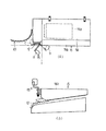
図1及び図2に示す如く、該キャビン25内における操作装置22の前端位置に、メーターパネルを上面部に有する操作台27を配置し、この操作台27の適宜位置にハンドル支軸28を回動可能に後傾立設し、このハンドル支軸28の上端部に円形ハンドル1を固定して設けると共に、この円形ハンドル1の中心部上面位置に、駐車時において制動作用状態でロックさせる駐車ブレーキボタン3を突設して構成させる。   As shown in FIGS. 1 and 2, an operating table 27 having a meter panel on the upper surface portion is arranged at the front end position of the operating device 22 in the cabin 25, and the handle support shaft 28 is rotated to an appropriate position of the operating table 27. A parking brake that is tilted rearward so as to be movable, and is provided with the circular handle 1 fixed to the upper end portion of the handle support shaft 28, and locked on the upper surface of the central portion of the circular handle 1 in a braking action state during parking. Button 3 is provided in a projecting manner.

該操作台27の下端部から後方にステップ29を延設し、このステップ29上に操作台27と相対して操作席23を配置させると共に、コンバインの走行状態を制動作用させる略L字状のブレーキペダル2の足踏プレート2aをステップ29上方に位置させ、その支点部2bをステップ29下面側の走行フレーム9に軸承して構成させる。   A step 29 is extended rearward from the lower end of the operation table 27, and the operation seat 23 is arranged on the step 29 so as to face the operation table 27, and the combine running state is braked. The foot plate 2a of the brake pedal 2 is positioned above the step 29, and the fulcrum portion 2b is supported by the traveling frame 9 on the lower surface side of the step 29.

該ブレーキペダル2の支点部2bより更に延長した後端部に、ブレーキワイヤ30の一端部を連結すると共に、このワイヤ30の他端部を、走行用ミッションケース31に内装した操向クラッチ及び走行ブレーキを作用させる左右の作用アーム32を左右同時に作動可能に連結して構成させる。   One end portion of the brake wire 30 is connected to the rear end portion further extended from the fulcrum portion 2b of the brake pedal 2, and the other end portion of the wire 30 is provided in the traveling transmission case 31 and the traveling clutch. The left and right action arms 32 that act on the brake are configured to be operatively connected to the left and right at the same time.

該ハンドル支軸28の中心部に駐車ブレーキロッド33を摺動可能に遊嵌貫通し、このロッド33の上端部は駐車ブレーキボタン3に係合させると共に、その下端部に、中間部を走行フレーム9にピン支承した駐車ロックアーム34の一端部をピン連結させ、このロックアーム34の他端部側にラック状の多数の切欠ぎ部34aを設け、この切欠ぎ部34aに嵌入させる駐車ロックプレート2cをブレーキペダル2の対応位置に突出固定して構成させる。   A parking brake rod 33 is slidably fitted through the central portion of the handle support shaft 28, and the upper end portion of the rod 33 is engaged with the parking brake button 3, and the intermediate portion is connected to the lower end portion of the traveling frame. The parking lock plate 34 is connected to one end of a parking lock arm 34 that is pin-supported by 9 and a plurality of rack-shaped notches 34a are provided on the other end of the lock arm 34, and is fitted into the notches 34a. 2c is protruded and fixed at the corresponding position of the brake pedal 2.

該ハンドル支軸28の下端部に、円形ハンドル1の回動により、進行方向の舵取りを行う操向電磁弁等を作用させるポテンショメータ等による舵取りセンサ35を取り付けて構成させる。なお、36及び37は、ブレーキペダル2及び駐車ロックアーム34を復帰させるリターンスプリングである。   A steering sensor 35 such as a potentiometer that operates a steering electromagnetic valve or the like that steers the traveling direction by rotating the circular handle 1 is attached to the lower end portion of the handle support shaft 28. Reference numerals 36 and 37 denote return springs for returning the brake pedal 2 and the parking lock arm 34.

このような構成により、コンバインの走行時に、円形ハンドル1の回動により舵取りセンサ35によって操向電磁弁を作用させ進行方向の舵取りを行わせると共に、走行を停止させるときはブレーキペダル2を踏み込んで走行ブレーキ(操向クラッチ)を作用させる。   With such a configuration, when the combine is traveling, the steering sensor 35 is operated by the steering sensor 35 by the rotation of the circular handle 1 to steer in the traveling direction, and the brake pedal 2 is depressed when the traveling is stopped. Apply the travel brake (steering clutch).

この走行ブレーキの作用時に、更に、駐車ブレーキ制動を行う必要があるときは、ブレーキペダル2を踏み込んだ状態で、駐車ブレーキボタン(駐車ブレーキ操作具)3の押し込み操作により駐車ブレーキロッド33を介して駐車ロックアーム34を作用させ、この駐車ロックアーム34の切欠ぎ部34aを該ペダル2の駐車ロックプレート2cに嵌入させることによって、ブレーキペダル2がロックされ駐車ブレーキ制動を行わせることができる。   When it is necessary to perform parking brake braking at the time of the operation of the traveling brake, the parking brake button (parking brake operating tool) 3 is pushed through the parking brake rod 33 while the brake pedal 2 is depressed. By applying the parking lock arm 34 and fitting the notch 34a of the parking lock arm 34 into the parking lock plate 2c of the pedal 2, the brake pedal 2 is locked and parking brake braking can be performed.

このように、駐車ブレーキ制動の操作を行う駐車ブレーキボタン3を、円形ハンドル1の中心部上面位置に配置することにより、操作が容易になると共に、ハンドル支軸28の中心部に駐車ブレーキロッド33を貫通させたリンク機構により、操作機構をコンパクトに構成することができる。   Thus, by arranging the parking brake button 3 for performing the parking brake braking operation at the upper surface position of the center portion of the circular handle 1, the operation becomes easy and the parking brake rod 33 is provided at the center portion of the handle support shaft 28. The operation mechanism can be configured compactly by the link mechanism through which is passed.

また、前記の如き円形ハンドル1を有するものにおいて、この円形ハンドル1を進行方向が直進状態の中立位置のときに、図3a及び図3bに示す如く、該ハンドル1の前側部を部分的に切り欠ぐと共に、該ハンドル1の中心部より右側の適宜位置に突起状の握り38を設けて構成させる。   Further, when the circular handle 1 has the circular handle 1 as described above, the front side portion of the circular handle 1 is partially cut off as shown in FIGS. At the same time, a protruding grip 38 is provided at an appropriate position on the right side of the center of the handle 1.

このような構成により、図4に示す如く、作業時にオペレータが前記分草体17による未刈穀稈の刈取り位置を容易に監視することができると共に、握り38を設けることにより、該ハンドル1が欠円となっていても連続して且つ片手で操作することができる。なお、握り38に、刈取装置5の昇降スイッチ38aを設け、従来のパワステ感覚で操作が行えるようにしてもよい。   With such a configuration, as shown in FIG. 4, the operator can easily monitor the cutting position of the uncut grain culm by the weed body 17 during the operation, and the handle 1 is not provided by providing the grip 38. Even if it is a circle, it can be operated continuously and with one hand. The grip 38 may be provided with a lift switch 38a of the reaping device 5 so that the operation can be performed in a conventional power steering sense.

また、前記の如き円形ハンドル1を有するものにおいて、図5aに示す如く、前記操作台27の右端側位置に、油圧式無段変速装置により前・後進の切り替え及び主変速を行わせる主変速レバー4を配設して構成させる。   Further, in the case having the circular handle 1 as described above, as shown in FIG. 5a, a main speed change lever that performs forward / reverse switching and main speed change by a hydraulic continuously variable transmission device at the right end side position of the operation console 27. 4 is arranged.

図5bに示す如く、該主変速レバー4の長柄上端部に設けた握り部4aの左側面(オペレータ側)に、上側から刈取装置5の上昇・下降の微調整を行う上下微調整ボタン(上下調整ボタン)6と、最上げ位置まで上昇させる上げボタン7と、下げ設定位置まで下降させる下げボタン8とを順次配置し、その右側面に下げ位置の設定を行う下げ位置設定ボタン39を配置して構成させる。   As shown in FIG. 5b, on the left side (operator side) of the grip 4a provided on the upper end of the long handle of the main transmission lever 4, an up / down fine adjustment button (up / down (Adjustment button) 6, an up button 7 for raising to the highest position, and a lower button 8 for lowering to the lower setting position are sequentially arranged, and a lower position setting button 39 for setting the lower position is arranged on the right side surface thereof. To configure.

このような構成により、円形ハンドル1を左手で握って操縦を行い、右手で主変速レバー4を握って車速の調節を行うと共に、頻繁に操作が必要となる刈取装置5の昇降調節を行う各調節ボタン6,7,8を親指で操作することができるから、オペレータは円形ハンドル1を握った操縦姿勢において、刈取装置5を昇降させるための屈み込むような変則的な動きを軽減することができる。   With such a configuration, the circular handle 1 is operated by being gripped with the left hand, the main speed change lever 4 is gripped with the right hand to adjust the vehicle speed, and the lifting / lowering adjustment of the reaping device 5 requiring frequent operation is performed. Since the adjustment buttons 6, 7, and 8 can be operated with the thumb, the operator can reduce anomalous movements such as bending to raise and lower the reaping device 5 in the steering posture with the circular handle 1 held. it can.

また、前記の如き円形ハンドル1を有するものにおいて、図6及び図7に示す如く、前記操作席23の右側部に配設した肘掛け40を、後端部の支軸40aにより上方へ回動可能とし、その前端部に前・後進の切り替え及び主変速を行わせる主変速レバー4を配置して構成させる。   Further, in the case having the circular handle 1 as described above, as shown in FIGS. 6 and 7, the armrest 40 disposed on the right side portion of the operation seat 23 can be rotated upward by the support shaft 40a at the rear end portion. And a main shift lever 4 for switching between forward and reverse and main shift is arranged at the front end portion.

該主変速レバー4上端部の握り部4aに刈取装置5を昇降調節させる調節ボタン類を設け、肘掛け40の内部に主変速レバー4から油圧式無段変速装置へ連結する操作ケーブル40bを配索して構成させる。   The grip 4a at the upper end of the main transmission lever 4 is provided with adjusting buttons for adjusting the lifting device 5 up and down, and an operation cable 40b for connecting the main transmission lever 4 to the hydraulic continuously variable transmission is arranged inside the armrest 40. To make it up.

このような構成により、肘掛け40を上方回動させることにより、乗降スペースが広くなりオペレータは楽に乗降できると共に、作業時は肘掛け40を通常位置に戻すことにより、主変速レバー4による走行操作及び調節ボタン類による刈取装置5の昇降操作を容易に行うことができる。   With such a configuration, the armrest 40 is turned upward to widen the boarding / exiting space, so that the operator can easily get on and off, and at the time of work, the armrest 40 is returned to the normal position so that the driving operation and adjustment by the main transmission lever 4 The raising / lowering operation of the cutting device 5 by buttons can be easily performed.

また、前記図6及び図7に示す如く、該円形ハンドル1と、操作席23に上方回動可能な肘掛け40を設けているものにおいて、肘掛け40を上方回動させたときに、この回動作用によって駐車ブレーキによる制動が可能となるよう連結構成させることにより、オペレータが操作席23から降りるときは必ず肘掛け40を上方回動させる必要があるから、この回動操作に連動して駐車ブレーキが作用し、車体26の動きをロックすることができ安全性が高い。   Further, as shown in FIGS. 6 and 7, when the circular handle 1 and the armrest 40 that can be rotated upward are provided on the operation seat 23, this turning operation is performed when the armrest 40 is rotated upward. When the operator gets out of the operation seat 23, the armrest 40 must be rotated upward by connecting the vehicle brake so that braking by the parking brake is possible. Acting, the movement of the vehicle body 26 can be locked, and safety is high.

また、前記図6及び図7に示す如く、該円形ハンドル1と、操作席23に上方回動可能な肘掛け40を設けているものにおいて、肘掛け40を上方回動させたときに、この回動作用によって刈取装置5の昇降作用を停止させる昇降停止スイッチ41を適宜位置に設けて接続構成させることにより、オペレータが操作席23から降りるときは必ず肘掛け40を上方回動させる必要があるから、この回動操作に連動して昇降停止スイッチ41が作用し、刈取装置5を停止することができ安全性が高い。   Further, as shown in FIGS. 6 and 7, when the circular handle 1 and the armrest 40 that can be rotated upward are provided on the operation seat 23, this turning operation is performed when the armrest 40 is rotated upward. Since the lifting / lowering stop switch 41 for stopping the lifting / lowering action of the reaping device 5 is provided at an appropriate position for connection, the armrest 40 must be rotated upward whenever the operator gets out of the operation seat 23. The raising / lowering stop switch 41 operates in conjunction with the turning operation, and the reaping device 5 can be stopped, which is highly safe.

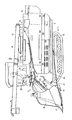
また、前記走行装置11について、平面視において左右側は同一形状であるから片側についてのみ説明を行う。図8に示す如く、走行フレーム9の平面視縦方向中央寄り左右位置に左右の縦主フレーム42を配置接合し、この縦主フレーム42の前側下部に支持枠43を設け、この支軸枠43に前部ローリングメタル44を固定して構成させる。   Moreover, about the said traveling apparatus 11, since the left and right sides are the same shape in planar view, only one side is demonstrated. As shown in FIG. 8, left and right vertical main frames 42 are arranged and joined to the left and right positions near the center in the vertical direction in the plan view of the traveling frame 9, and a support frame 43 is provided at the front lower portion of the vertical main frame 42. The front rolling metal 44 is fixed and configured.

該ローリングメタル44に、く字状の前部ローリングアーム45を中間部位置から上下部分に分割して前部ローリング軸46により軸支すると共に、前部ローリングアーム45の下端部位置と、該縦主フレーム42の外側下方に平行して位置する転輪フレーム47の前部側位置とを、回動可能にピン45a連結して構成させる。   A rectangular front rolling arm 45 is divided into an upper and lower portion from the middle position on the rolling metal 44 and is pivotally supported by a front rolling shaft 46, and a lower end position of the front rolling arm 45, A pin 45a is pivotally connected to the front side position of the wheel frame 47 located in parallel with the outer lower side of the main frame 42.

該縦主フレーム42の後側下部に固定したピッチングメタル48にピッチング軸49を軸承し、このピッチング軸49にピッチングアーム50の一端部を軸止すると共に、その他端部と平面視H字状の連結アーム51の一端部とを回動可能にピン51a連結して構成させる。   A pitching shaft 49 is supported by a pitching metal 48 fixed to the rear lower portion of the vertical main frame 42, and one end portion of the pitching arm 50 is fixed to the pitching shaft 49, and the other end portion is H-shaped in plan view. A pin 51a is rotatably connected to one end of the connecting arm 51.

該連結アーム51の他端部に、く字状の後部ローリングアーム52を中間部位置から上下部分に分割して後部ローリング軸53により軸支すると共に、後部ローリングアーム52の下端部位置と、該転輪フレーム47の後部側位置とを回動可能にピン52a連結して構成させる。   At the other end of the connecting arm 51, a rectangular rear rolling arm 52 is divided from the middle position into upper and lower parts and pivotally supported by the rear rolling shaft 53, and the lower end position of the rear rolling arm 52, A pin 52a is connected to the rear side position of the wheel frame 47 so as to be rotatable.

該一方のピッチングアーム50他端部側で連結アーム51の連結部より少し延長した突起部50aに、該一方の縦主フレーム42から立ち上げたシリンダ取付アーム54に固定側を取り付けた略鉛直姿勢のピッチングシリンダ55のピストン先端部を連結して構成させる。   A substantially vertical posture in which the fixed side is attached to the cylinder mounting arm 54 raised from the one vertical main frame 42 to the protrusion 50a slightly extended from the connecting portion of the connecting arm 51 on the other end side of the one pitching arm 50. The piston tip of the pitching cylinder 55 is connected and configured.

前記前部ローリングアーム45の上端部位置と後部ローリングアーム52の上部中間位置とを、4点平行リンクを形成可能に連結杆56によって回動可能にピン45b,52b連結すると共に、後部ローリングアーム52をピン52b連結位置より更に上方側へ延長し、その上端部にローリングシリンダ57のピストン先端部を連結して構成させる。   The upper end position of the front rolling arm 45 and the upper middle position of the rear rolling arm 52 are connected to pins 45b and 52b by a connecting rod 56 so as to be able to form a four-point parallel link, and to the rear rolling arm 52. Is extended further upward than the connecting position of the pin 52b, and the piston tip of the rolling cylinder 57 is connected to the upper end thereof.

該ローリングシリンダ57の固定側と、該ピッチングアーム50の突起部50aの一部とに帯状の保持板58により両側から挟む状態で回動可能に各々ピン連結し、該固定側の連結部をリンク59を介して揺動可能に該縦主フレーム42に取り付けて構成させる。なお、60は、前記転輪フレーム47に適宜間隔にて軸支した接地転輪である。   The fixed side of the rolling cylinder 57 and a part of the protruding portion 50a of the pitching arm 50 are respectively pin-coupled so as to be able to rotate while being sandwiched from both sides by a belt-like holding plate 58, and the fixed-side connecting portion is linked. A vertical main frame 42 is swingably mounted via 59. Reference numeral 60 denotes a grounding wheel that is pivotally supported on the wheel frame 47 at an appropriate interval.

このような構成により、ピッチングシリンダ55を作用させたときは、連結アーム51を介した後部ローリングアーム52の上下により転輪フレーム47を後傾斜させるピッチング制御を行うことができると共に、ローリングシリンダ57を作用させたときは、前部ローリングアーム45と連結アーム51を介した後部ローリングアーム52及び連結杆56による平行リンク作用により、転輪フレーム47を平行上下させるローリング制御を行わせることができる。   With such a configuration, when the pitching cylinder 55 is operated, it is possible to perform pitching control in which the wheel frame 47 is tilted rearward by the upper and lower of the rear rolling arm 52 via the connecting arm 51, and the rolling cylinder 57 is When operated, the rolling control for moving the wheel frame 47 in parallel up and down by the parallel link action by the rear rolling arm 52 and the connecting rod 56 via the front rolling arm 45 and the connecting arm 51 can be performed.

しかし、ローリング制御のみを行うものでは、ピッチングメタル48,ピッチング軸49,ピッチングアーム50,シリンダ取付アーム54,ピッチングシリンダ55,保持板58等(図の斜線部分)が不要となり、代わりに連結アーム51の一端部を支承するアーム支持メタル61とローリングシリンダ57を支承するシリンダ支持メタル62とを(図の網掛け部分)、各々該縦主フレーム42に取り付けてローリング専用仕様とすることができる。   However, in the case of performing only rolling control, the pitching metal 48, the pitching shaft 49, the pitching arm 50, the cylinder mounting arm 54, the pitching cylinder 55, the holding plate 58, etc. (shaded portions in the figure) are not necessary. An arm support metal 61 that supports one end of the cylinder and a cylinder support metal 62 that supports the rolling cylinder 57 (shaded portions in the figure) can be attached to the vertical main frame 42 for exclusive rolling.

このように、ピッチング制御とローリング制御の仕様変更が容易であり共用化が可能になると共に、図9に示す従来機の如く、前部ローリングメタル44の支持枠43と同様に後部ローリングメタル44aとその支持枠43aを設ける必要がないから、ローリングの後方支点部に大きな側面形状(図の斜線部分)を有することがなく、左右方向への泥抜けが良好となり旋回性が向上すると共に、洗車も容易である。   As described above, the specifications of the pitching control and the rolling control can be easily changed and shared, and the rear rolling metal 44a and the support frame 43 of the front rolling metal 44 can be used as in the conventional machine shown in FIG. Since it is not necessary to provide the support frame 43a, the rear fulcrum portion of the rolling does not have a large side shape (the hatched portion in the figure), the mud in the right and left direction is improved, the turning performance is improved, and the car wash is also performed. Easy.

また、図10に示す如く、CPUを主体的に配してピッチング及びローリング機能を制御するコントローラ63を設け、このコントローラ63の入力側に、車速を検出する車速センサ64と、パワステレバーの左右傾動操作による車体26の旋回作用をON・OFFする旋回スイッチ65と、パワステレバーの前後傾動操作による刈取装置5の昇降作用をON・OFFする昇降スイッチ66とを各々接続して構成させる。   Further, as shown in FIG. 10, a controller 63 for controlling the pitching and rolling functions by providing a central CPU is provided. On the input side of the controller 63, a vehicle speed sensor 64 for detecting the vehicle speed, and a left / right tilt of the power steering lever are provided. A turning switch 65 for turning on / off the turning action of the vehicle body 26 by an operation and a raising / lowering switch 66 for turning on / off the raising / lowering action of the reaping device 5 by a tilting operation of the power steering lever are connected to each other.

該コントローラ63の出力側に、前記ピッチングシリンダ55を作動させるピッチング電磁弁67と、左右のローリングシリンダ57を作動させる左右のローリング電磁弁68とを各々接続して構成させる。   A pitching electromagnetic valve 67 for operating the pitching cylinder 55 and left and right rolling electromagnetic valves 68 for operating the left and right rolling cylinders 57 are connected to the output side of the controller 63, respectively.

このような構成により、一定速度以上で旋回を行ったときは、その後一定時間は左右のローリング機能を自動的に停止させる制御と、一定時間内に所定以上の車速差が生じたときは、その後一定時間はピッチング機能を自動的に停止させる制御と、前記伸縮シリンダ21の調節が一定時間内に所定以上の調節変位を生じたときは、その後一定時間はピッチング機能を自動的に停止させる制御とを行わせる。   With such a configuration, when turning at a certain speed or higher, the control that automatically stops the left and right rolling functions for a certain time thereafter, and when a vehicle speed difference of a predetermined value or more occurs within a certain time, A control for automatically stopping the pitching function for a certain period of time, and a control for automatically stopping the pitching function for a certain period of time after the adjustment of the telescopic cylinder 21 causes an adjustment displacement of a predetermined value or more within a certain period of time. To do.

これらの制御を行うことにより、車体26の水平制御が誤作動を起こす要因の発生を自動的に認知し、一時的に水平制御機能を停止させることにより誤作動を未然に防止することができる。   By performing these controls, it is possible to automatically recognize the occurrence of a factor that causes the horizontal control of the vehicle body 26 to malfunction, and to prevent malfunction by temporarily stopping the horizontal control function.

また、図11に示す如く、CPUを主体的に配して車体26の前後傾斜時に左右の走行ブレーキ制動手段69aを内蔵したコントローラ69を設け、このコントローラ69の入力側に、駐車ブレーキの作用状態を検出する駐車ブレーキスイッチ70と、車体26の前後傾斜を検出する前後傾斜位置センサ71とを各々接続して構成させる。   Further, as shown in FIG. 11, a controller 69 is provided in which a CPU is mainly arranged and the left and right traveling brake braking means 69a are built in when the vehicle body 26 is tilted back and forth. The parking brake switch 70 for detecting the vehicle and the front / rear inclination position sensor 71 for detecting the front / rear inclination of the vehicle body 26 are connected to each other.

該コントローラ69の出力側に、前記走行用ミッションケース31に内装している左右の操向クラッチを入・切する左右の操向クラッチ電磁弁72と、左右の走行ブレーキを制動する左右の走行ブレーキ減圧弁73とを各々接続して構成させる。   On the output side of the controller 69, left and right steering clutch solenoid valves 72 for turning on and off the left and right steering clutches built in the traveling mission case 31, and left and right traveling brakes for braking the left and right traveling brakes. A pressure reducing valve 73 is connected to each other.

このような構成により、車体26が自然降下するような傾斜地において、駐車ブレーキの制動時に駐車ブレーキスイッチ70がONすることにより、電気的に素早く走行ブレーキを制動させることができるから、従来の如く、駐車ブレーキを素早く操作できないときは、左右の操向クラッチは切り状態にあるため走行ブレーキが制動される前に車体26が自然に降下するという不具合を解消して、傾斜地においても安全性の高い駐車ブレーキ制動を行うことができる。   With such a configuration, the driving brake can be electrically quickly braked by turning on the parking brake switch 70 when the parking brake is braked on an inclined ground where the vehicle body 26 naturally descends. When the parking brake cannot be operated quickly, the left and right steering clutches are in the disengaged state, eliminating the problem that the vehicle body 26 naturally descends before the traveling brake is braked, and highly safe parking even on sloping ground Brake braking can be performed.

また、図12a及び図12bに示す如く、前記脱穀装置15の扱胴74aを内装する脱穀室74の入口部にサイドミラー75を取り付け、コンバインの脱穀作業時の監視を行うものにおいて、従来では、このミラー75は手扱ぎ作業時に邪魔にならないよう通常作業位置aから後方の手扱ぎ作業位置bへ回動させるものが一般的であるが、作業終了後はこのミラー75が車体26から外方へ突出しているため、運搬時や格納時に邪魔になると共に破損する恐れがあった。   In addition, as shown in FIGS. 12a and 12b, a side mirror 75 is attached to the inlet portion of the threshing chamber 74 in which the handling cylinder 74a of the threshing device 15 is installed, and in the past, monitoring during the threshing operation of the combine, The mirror 75 is generally rotated from the normal working position a to the rear handling work position b so that it does not get in the way during handling operations. Since it protrudes in the direction, it may become a hindrance and breakage during transportation and storage.

このため、図13に示す如く、該サイドミラー75を回動可能に支持するミラー支持筒75aを、脱穀装置15の挟持杆カバー74bの前端部に固定したコ字状の取付アーム75bに固着し、ミラー支持筒75aの上端部円周上に多数の分割溝75cを設け、この分割溝75cに嵌入する位置決めピン75dをミラー本体75eを支持するクランク状のミラー支持軸75fに貫通固定すると共に、このミラー支持軸75fを軸方向に張圧するスプリング75gを軸端部に設けて構成させる。   For this reason, as shown in FIG. 13, the mirror support cylinder 75a that rotatably supports the side mirror 75 is fixed to a U-shaped mounting arm 75b fixed to the front end portion of the sandwiching rod cover 74b of the threshing device 15. A plurality of dividing grooves 75c are provided on the circumference of the upper end portion of the mirror support cylinder 75a, and a positioning pin 75d fitted into the dividing groove 75c is fixed to the crank-shaped mirror support shaft 75f that supports the mirror body 75e. A spring 75g for tensioning the mirror support shaft 75f in the axial direction is provided at the shaft end.

このような構成により、サイドミラー75の回動位置を、通常のコンバイン作業時には通常作業位置aにロックし、手扱ぎ作業時にはミラー支持軸75fをスプリング75gに抗して引き上げて位置決めピン75dを分割溝75cにより移動させ手扱ぎ作業位置bへロックする。次に、作業終了に伴いコンバインを運搬及び格納する際には、該ミラー75を車体26幅内に収納する収納位置cへロックさせることができる。   With such a configuration, the rotation position of the side mirror 75 is locked at the normal work position a during normal combine work, and the mirror support shaft 75f is lifted against the spring 75g during hand handling work to lift the positioning pin 75d. It is moved by the dividing groove 75c and locked to the hand handling work position b. Next, when the combine is transported and stored at the end of the work, the mirror 75 can be locked to the storage position c in which it is stored within the width of the vehicle body 26.

このように、サイドミラー75の回動位置を、そのときの状態に応じて簡単に最適位置へロックすることができるから、作業時に邪魔になったり、格納時に余分なスペースを必要としたり、トラックに乗せた運搬時等において樹木に引っ掛けたりする障害を防止することができる。   In this way, the rotational position of the side mirror 75 can be easily locked to the optimal position according to the state at that time, so that it becomes an obstacle during work, requires extra space during storage, It is possible to prevent obstacles such as being caught on a tree during transportation on board.

1 円形ハンドル
4 主変速レバー
4a 握り部
5 作業部
6 上下微調整ボタン(上下調整ボタン)
7 上げボタン
8 下げボタン
1 circular handle 4 main transmission lever 4a grip part 5 working part 6 vertical fine adjustment button (vertical adjustment button)
7 Raise button 8 Lower button

Claims (1)

進行方向の舵取りを行う円形ハンドル(1)と、この円形ハンドル(1)の一側方に配置して前進または後進の切り替え及び走行速度の主変速を行う主変速レバー(4)とを有し、該主変速レバー(4)の上端部に設けた握り部(4a)のオペレータ側の面に、作業部(5)の上げ下げの調整を行う上下調整ボタン(6)と、作業部(5)の設定位置までの下げを行う下げボタン(8)及び上げを行う上げボタン(7)とを設けたことを特徴とする作業車の操作装置。 A circular handle (1) that steers in the traveling direction, and a main transmission lever (4) that is disposed on one side of the circular handle (1) and performs forward / reverse switching and main shift of the traveling speed. A vertical adjustment button (6) for adjusting the raising and lowering of the working part (5) on the operator side surface of the grip part (4a) provided at the upper end of the main transmission lever (4), and the working part (5) A working vehicle operating device comprising a lowering button (8) for lowering to a set position and a raising button (7) for raising.
JP2009094042A 2009-04-08 2009-04-08 Working vehicle operating device Expired - Fee Related JP4888514B2 (en)

Priority Applications (1)

Application Number Priority Date Filing Date Title
JP2009094042A JP4888514B2 (en) 2009-04-08 2009-04-08 Working vehicle operating device

Applications Claiming Priority (1)

Application Number Priority Date Filing Date Title
JP2009094042A JP4888514B2 (en) 2009-04-08 2009-04-08 Working vehicle operating device

Related Parent Applications (1)

Application Number Title Priority Date Filing Date
JP2000256024A Division JP4432234B2 (en) 2000-08-25 2000-08-25 Combine

Related Child Applications (1)

Application Number Title Priority Date Filing Date
JP2011095215A Division JP5062346B2 (en) 2011-04-21 2011-04-21 Combine

Publications (2)

Publication Number Publication Date
JP2009149308A true JP2009149308A (en) 2009-07-09
JP4888514B2 JP4888514B2 (en) 2012-02-29

Family

ID=40918965

Family Applications (1)

Application Number Title Priority Date Filing Date
JP2009094042A Expired - Fee Related JP4888514B2 (en) 2009-04-08 2009-04-08 Working vehicle operating device

Country Status (1)

Country Link
JP (1) JP4888514B2 (en)

Families Citing this family (1)

* Cited by examiner, † Cited by third party
Publication number Priority date Publication date Assignee Title
TW201124655A (en) 2009-09-03 2011-07-16 Ulvac Inc Gate valve

Citations (7)

* Cited by examiner, † Cited by third party
Publication number Priority date Publication date Assignee Title
JPS62138669U (en) * 1985-11-06 1987-09-01
JPH09131101A (en) * 1996-10-30 1997-05-20 Iseki & Co Ltd Operation lever unit for powered vehicle
JPH1066437A (en) * 1996-08-27 1998-03-10 Yanmar Agricult Equip Co Ltd Operating device of traveling agricultural apparatus
JPH1156011A (en) * 1997-08-27 1999-03-02 Iseki & Co Ltd Operating device in combine harvester
JPH11243752A (en) * 1998-03-03 1999-09-14 Yanmar Agricult Equip Co Ltd Ordinary type combine harvester
JP2000032832A (en) * 1998-07-17 2000-02-02 Seirei Ind Co Ltd Combine provided with rotational steering wheel mechanism
JP2000185633A (en) * 1998-12-24 2000-07-04 Kanzaki Kokyukoki Mfg Co Ltd Parking brake device

Patent Citations (7)

* Cited by examiner, † Cited by third party
Publication number Priority date Publication date Assignee Title
JPS62138669U (en) * 1985-11-06 1987-09-01
JPH1066437A (en) * 1996-08-27 1998-03-10 Yanmar Agricult Equip Co Ltd Operating device of traveling agricultural apparatus
JPH09131101A (en) * 1996-10-30 1997-05-20 Iseki & Co Ltd Operation lever unit for powered vehicle
JPH1156011A (en) * 1997-08-27 1999-03-02 Iseki & Co Ltd Operating device in combine harvester
JPH11243752A (en) * 1998-03-03 1999-09-14 Yanmar Agricult Equip Co Ltd Ordinary type combine harvester
JP2000032832A (en) * 1998-07-17 2000-02-02 Seirei Ind Co Ltd Combine provided with rotational steering wheel mechanism
JP2000185633A (en) * 1998-12-24 2000-07-04 Kanzaki Kokyukoki Mfg Co Ltd Parking brake device

Also Published As

Publication number Publication date
JP4888514B2 (en) 2012-02-29

Similar Documents

Publication Publication Date Title
US7434379B2 (en) Apparatus for vertically moving mower unit for riding mower
JP5062346B2 (en) Combine
JP4888514B2 (en) Working vehicle operating device
JP4432234B2 (en) Combine
JP2008253231A (en) Traveling vehicle body
JP4952724B2 (en) Passenger rice transplanter
JP4502107B2 (en) Passenger rice transplanter
JP4330581B2 (en) Work machine operation structure
JP2004121013A (en) Auxiliary clutch operation structure for sulky rice transplanter
JP6253057B2 (en) Work vehicle and control method of lifting device
JP2002238325A (en) Sulky lawn mower
JPH0750897Y2 (en) Combine
JP2000262106A (en) Tending working vehicle
JP2006099808A5 (en)
JP2003259703A (en) Hydraulic lifting and lowering apparatus for tractor
JP3717400B2 (en) Work machine operation structure
JP3625929B2 (en) Combine
JP4935464B2 (en) Tractor
JP2009035086A (en) Working vehicle
JP2002196833A (en) Maneuvering structure of work machine
JP2007286940A (en) Operating lever guiding device
JP2002274411A (en) Steering operation part of combined harvester and thresher
JP2007286940A5 (en)
JP2001206228A (en) Steering system for tractor
JPH06219342A (en) Running posture control device for combine

Legal Events

Date Code Title Description
A621 Written request for application examination

Free format text: JAPANESE INTERMEDIATE CODE: A621

Effective date: 20090425

A977 Report on retrieval

Free format text: JAPANESE INTERMEDIATE CODE: A971007

Effective date: 20110209

A131 Notification of reasons for refusal

Free format text: JAPANESE INTERMEDIATE CODE: A131

Effective date: 20110222

A521 Written amendment

Free format text: JAPANESE INTERMEDIATE CODE: A523

Effective date: 20110420

A131 Notification of reasons for refusal

Free format text: JAPANESE INTERMEDIATE CODE: A131

Effective date: 20110719

A521 Written amendment

Free format text: JAPANESE INTERMEDIATE CODE: A523

Effective date: 20110817

TRDD Decision of grant or rejection written
A01 Written decision to grant a patent or to grant a registration (utility model)

Free format text: JAPANESE INTERMEDIATE CODE: A01

Effective date: 20111115

A01 Written decision to grant a patent or to grant a registration (utility model)

Free format text: JAPANESE INTERMEDIATE CODE: A01

A61 First payment of annual fees (during grant procedure)

Free format text: JAPANESE INTERMEDIATE CODE: A61

Effective date: 20111128

R150 Certificate of patent (=grant) or registration of utility model

Free format text: JAPANESE INTERMEDIATE CODE: R150

FPAY Renewal fee payment (prs date is renewal date of database)

Free format text: PAYMENT UNTIL: 20141222

Year of fee payment: 3

LAPS Cancellation because of no payment of annual fees